


Research on a Data-Driven Modeling Method for Precast Concrete Balcony Components


Abstract
:1. Introduction
2. The Challenges in the Modeling of PC Balcony Components
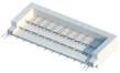
2.1. Classification of PC Balcony Elements
2.2. The Challenges in Modeling PC Balcony Elements
- The information regarding the components is widely scattered, indicating a relatively low level of informatization.
- 2.
- The software operation is intricate, and the modeling efficiency is suboptimal.
3. Methods
3.1. Concepts and Techniques of Data-Driven Modeling
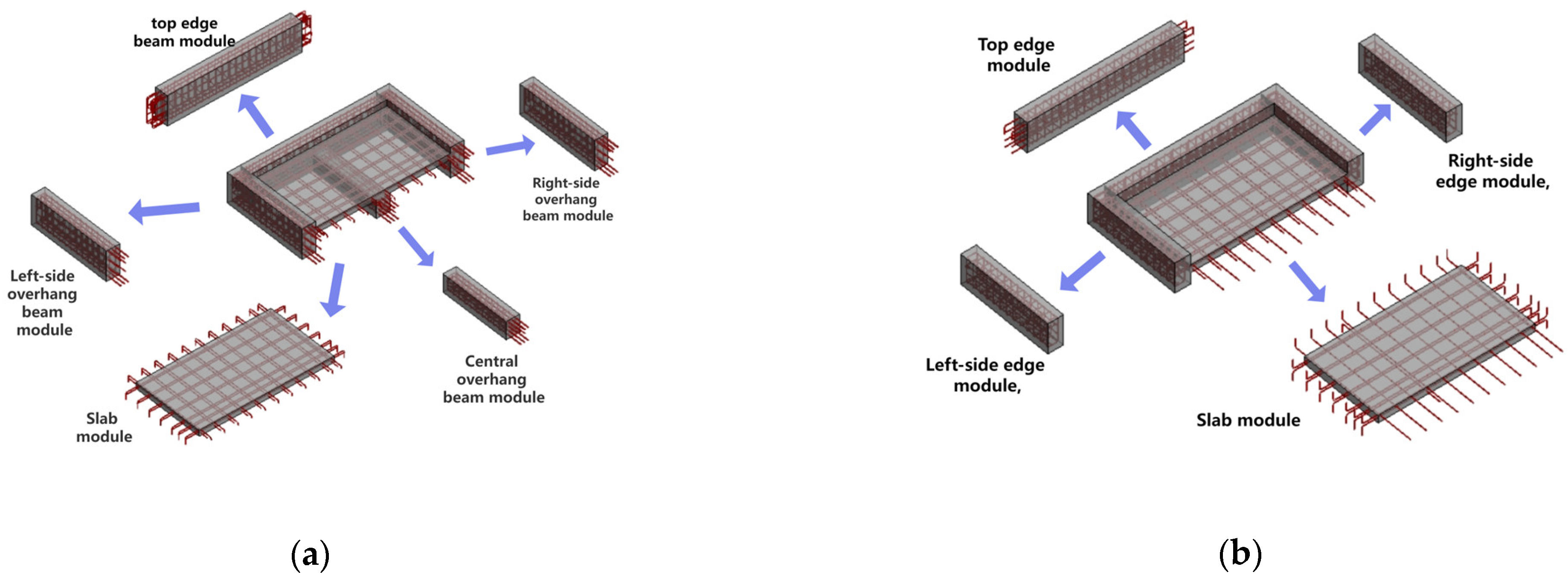
3.2. Modularization of Prefabricated Balcony Components
3.2.1. Modular Splitting
3.2.2. The Establishment of a Modular Dataset
3.2.3. Component Data Structure Design
3.3. Revit Secondary Development
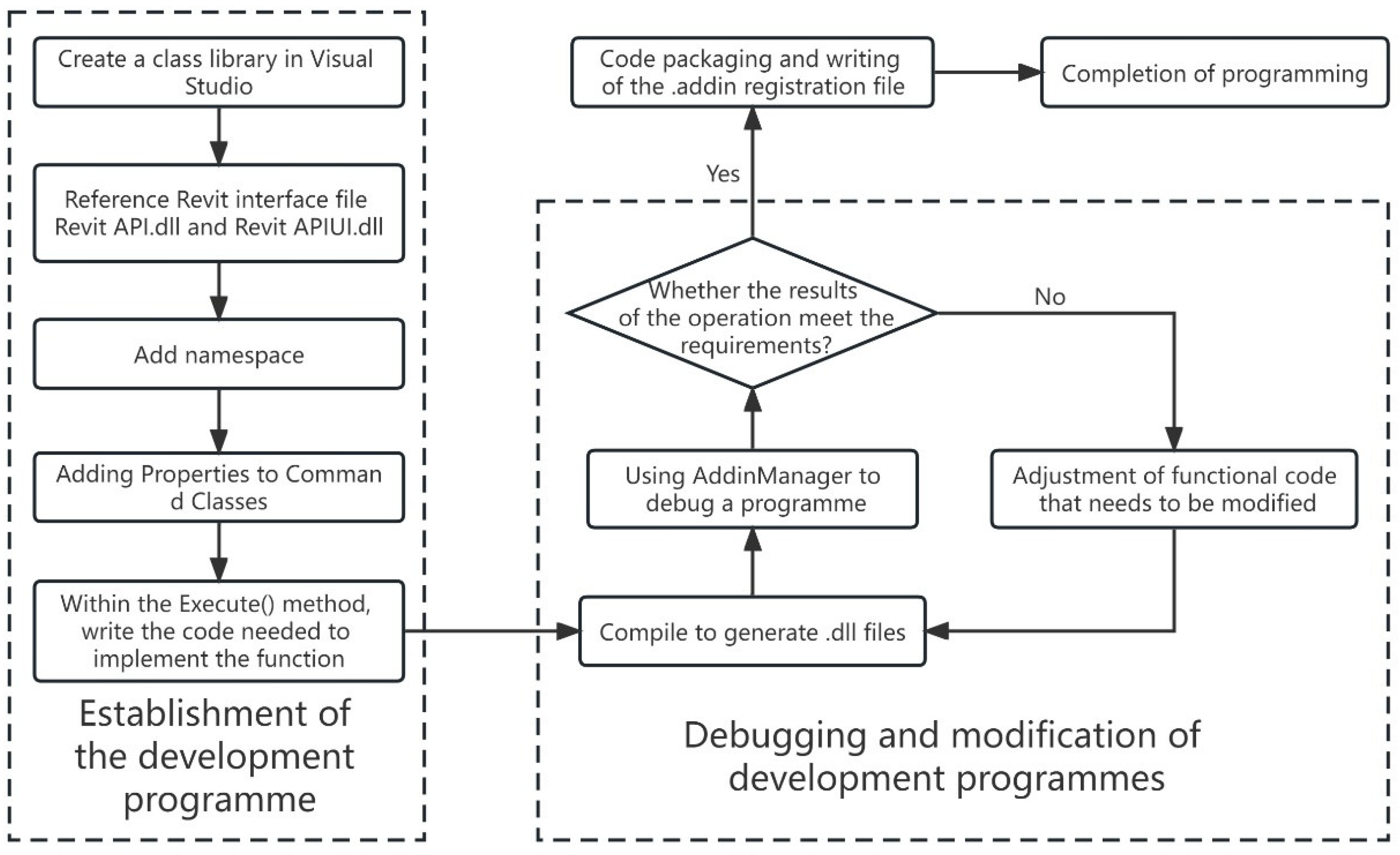
3.3.1. Development Platforms and Processes
3.3.2. The Process of Tool Development
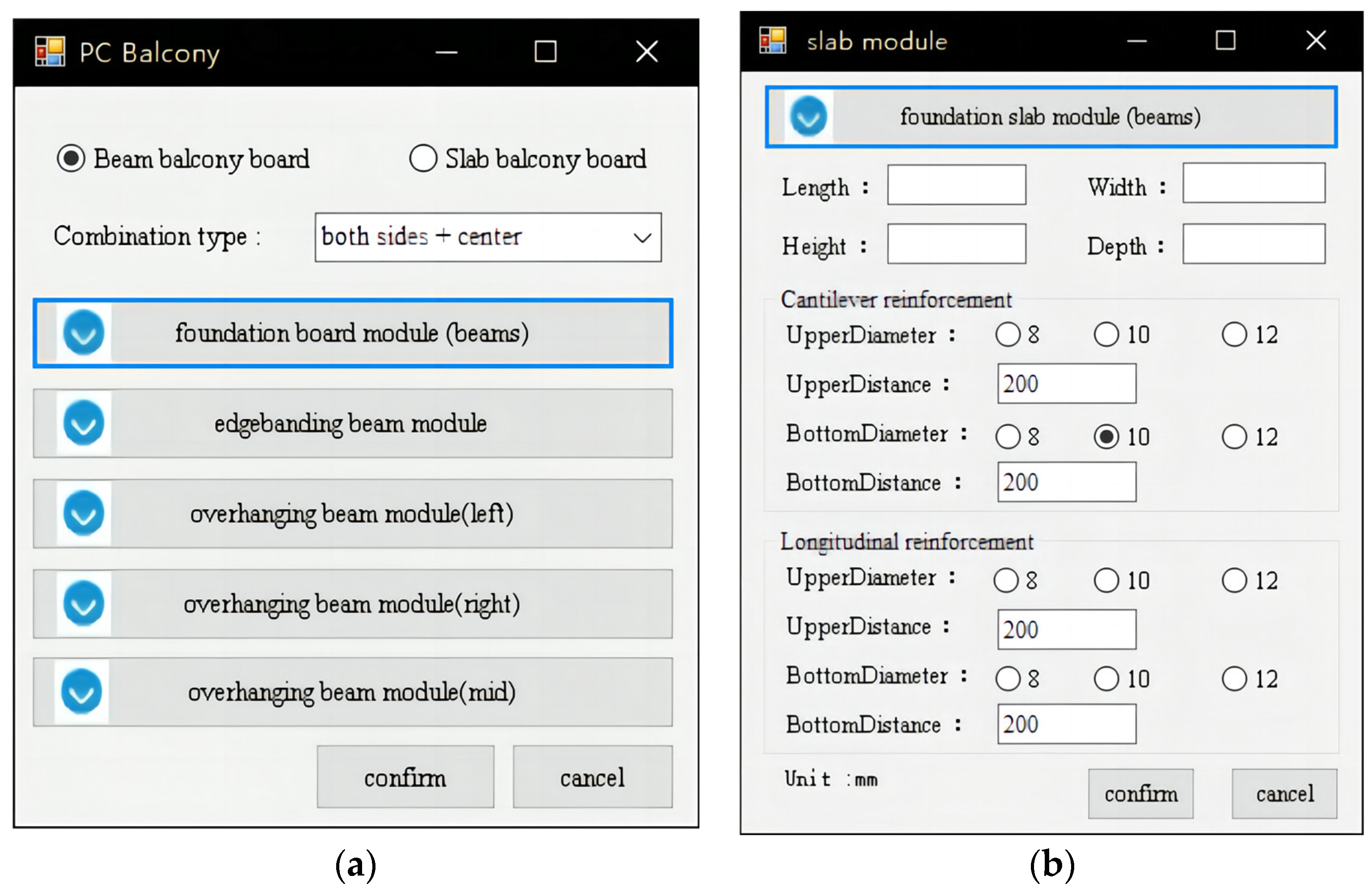
- User interface (UI) design
- 2.
- Establishment of a solid model of the PC balcony
- 3.
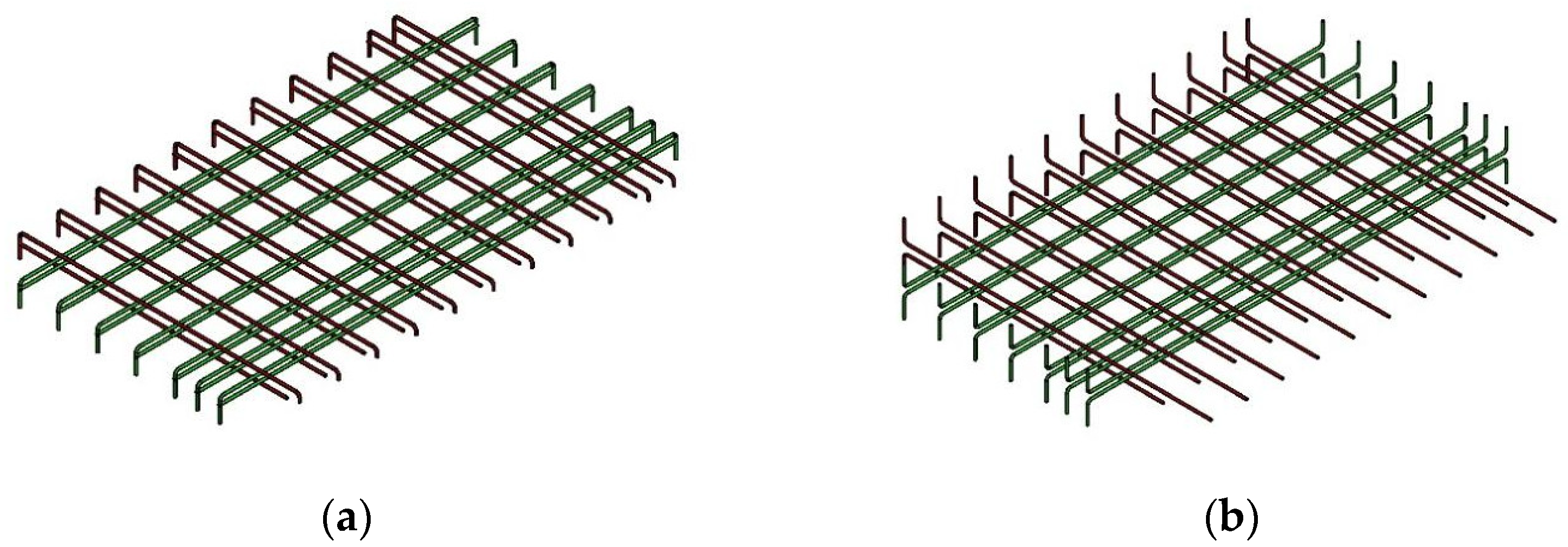
- Establishment of rebars model of the PC balcony
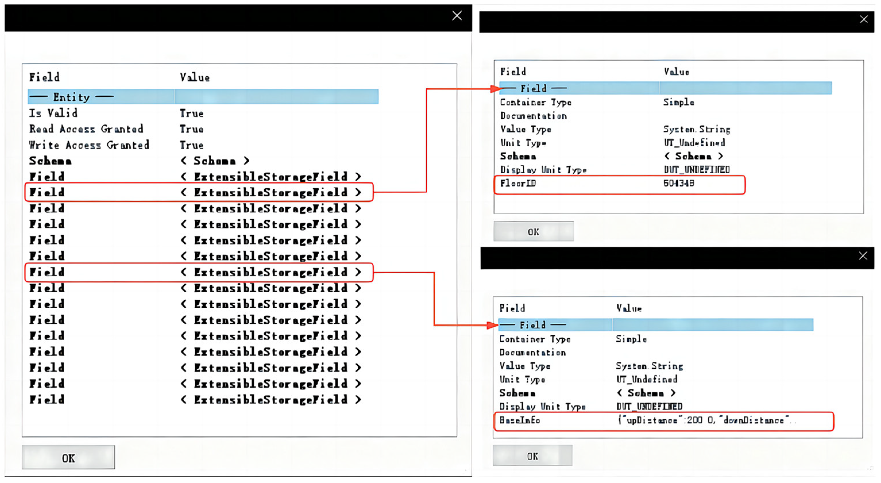
3.3.3. Dataset Storage and Inquiry for Models
- The function for the dictionary dataset must be designed as follows: Dictionary<string, string> to create the relevant dataset based on the type of balcony.
- In the corresponding dictionary dataset function, the module dataset name is set to Field, while the parameter name and its respective attribute values are allocated to the following value field: Serializes Object.
- Unique data tag GUID values are stored in the generated instance model data.
- Finally, all the data are stored on the model and supplied to the user for querying.
- Revit Lookup may be used to read the unique data tag GUID value stored in the model data in this instance.
- Since each GUID value is unique, it can be used to look up the dictionary dataset function Dictionary<string, string> for this model.
- The module dataset names and their corresponding attribute values in the dictionary dataset function can be inquired about, and their specific correspondence is shown in Table 4.
4. Case Study
4.1. Project Overview and Modeling Process
- Load the modeling tool to the Revit TAB and access the interface of the modeling tool.
- According to the drawing information, select the beam balcony model, and upon the selection of ‘Both sides form’ from the drop-down menu, the corresponding parameter set interface button appears automatically.
- Click the corresponding button and input data in the respective sub-interface that appears.
- Select the reference coordinate point for generating the balcony component. The driver generates the PC balcony component at the corresponding position to complete the establishment of a single model.
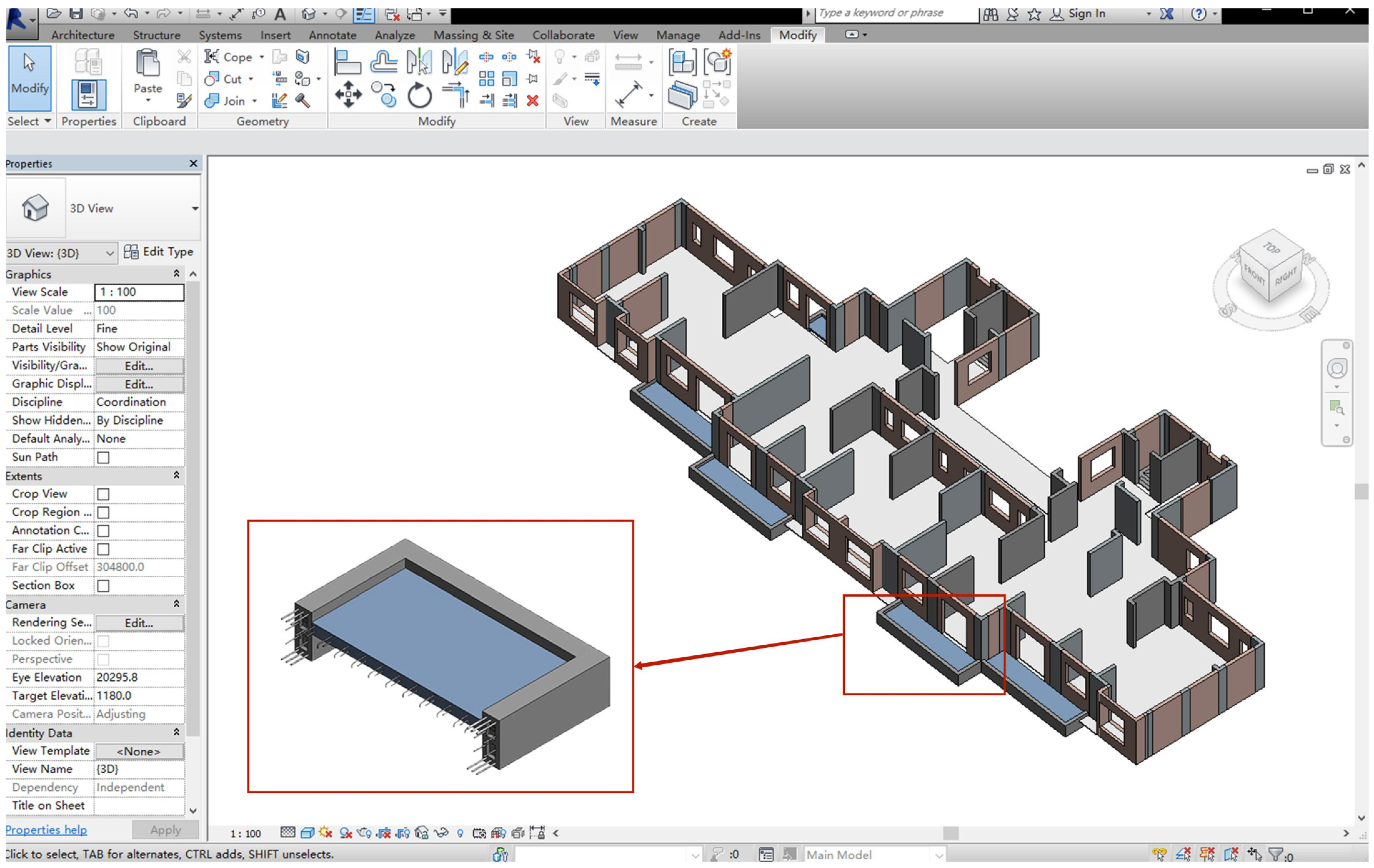
- Repeat the aforementioned steps to finalize the installation of the remaining PC balcony components on the standard floor. The modeling outcomes of the standard layer are illustrated in the subsequent Figure 12.
4.2. Application Results
5. Discussion
6. Conclusions
- The combination of data-driven modeling methods and BIM technology enhances the efficiency and quality of modeling for PC balcony components. In terms of modeling time, the beam balcony and slab balcony modeling times reduce by 17 and 14 min, respectively, compared to the traditional modeling method. In terms of model quality, the LOD accuracy level is used to assess the model’s quality. The proposed method achieves a model accuracy level of LOD400, surpassing the LOD350 accuracy level achieved using the traditional method, thereby validating the efficacy of this novel approach in enhancing modeling efficiency.
- In this study, a modeling software tool for PC balcony model was developed based on the Revit software platform, which used a data driver program to establish the model. This software was successfully applied in an actual project, achieving a completion rate of 93.01% for PC balcony components. Consequently, it effectively addresses the issue of 3D modeling software’s inability to directly generate such components and significantly reduces operational complexities for modelers.
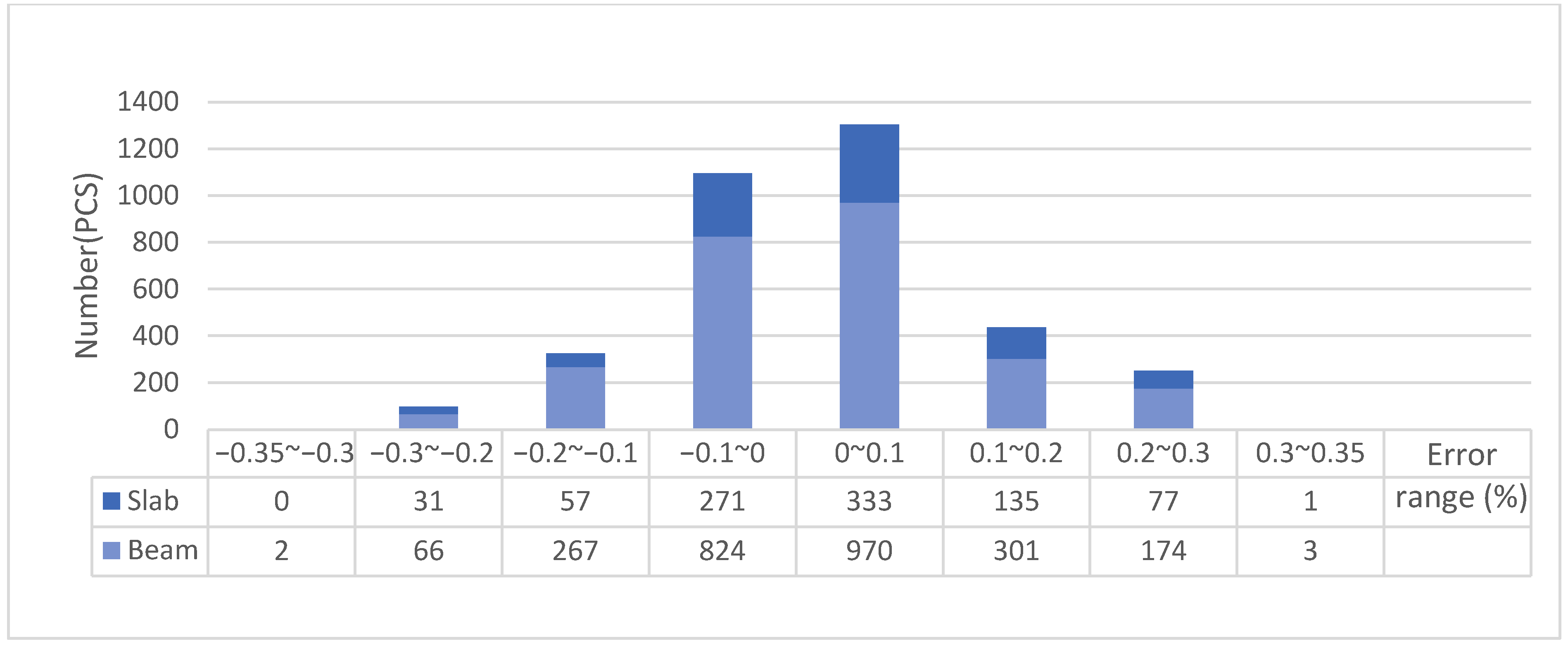
- The study adopted a data-driven modeling approach and used a modular strategy to divide the PC balcony components. It also designed the corresponding module dataset and model data structure. By analyzing the model data and statistically evaluating the error values, a 100% data reading rate was achieved, with a maximum error within ±0.35%. This confirms the reliability of the designed data structure stability in this study and effectively resolves any discrepancies between the data and the model caused by deviations. It serves as a dependable data source for the production of prefabricated components, mitigating the challenges arising from scattered information sources in the model and enhancing the level of model information.
Author Contributions
Funding
Data Availability Statement
Conflicts of Interest
References
- Cao, X.; Li, X.; Zhu, Y.; Zhang, Z. A Comparative Study of Environmental Performance between Prefabricated and Traditional Residential Buildings in China. J. Clean. Prod. 2015, 109, 131–143. [Google Scholar] [CrossRef]
- Liu, W.; Zhang, H.; Wang, Q.; Hua, T.; Xue, H. A Review and Scientometric Analysis of Global Research on Prefabricated Buildings. Adv. Civ. Eng. 2021, 2021, 8869315. [Google Scholar] [CrossRef]
- Banihashemi, S.; Tabadkani, A.; Hosseini, M.R. Integration of Parametric Design into Modular Coordination: A Construction Waste Reduction Workflow. Autom. Constr. 2018, 88, 1–12. [Google Scholar] [CrossRef]
- Kamali, M.; Hewage, K. Life Cycle Performance of Modular Buildings: A Critical Review. Renew. Sustain. Energy Rev. 2016, 62, 1171–1183. [Google Scholar] [CrossRef]
- Tam, V.W.Y.; Fung, I.W.H.; Sing, M.C.P.; Ogunlana, S.O. Best Practice of Prefabrication Implementation in the Hong Kong Public and Private Sectors. J. Clean. Prod. 2015, 109, 216–231. [Google Scholar] [CrossRef]
- Yang, S.; Hou, Z.; Chen, H. Network Model Analysis of Quality Control Factors of Prefabricated Buildings Based on the Complex Network Theory. Buildings 2022, 12, 1874. [Google Scholar] [CrossRef]
- Yuan, Z.; Sun, C.; Wang, Y. Design for Manufacture and Assembly-Oriented Parametric Design of Prefabricated Buildings. Autom. Constr. 2018, 88, 13–22. [Google Scholar] [CrossRef]
- Li, Y.; Ni, Y.; Zhang, N.; Liu, Z. Modularization for the Complex Product Considering the Design Change Requirements. Res. Eng. Des. 2021, 32, 507–522. [Google Scholar] [CrossRef]
- Qi, B.; Costin, A. BIM and Ontology-Based DfMA Framework for Prefabricated Component. Buildings 2023, 13, 394. [Google Scholar] [CrossRef]
- Dong, D.; Zou, Y.; Pan, H.; Zhou, G.; Feng, Y.; Tang, Y. DFMA-Oriented Modular and Parametric Design and Secondary Splitting of Vertical PC Components. Sci. Rep. 2023, 13, 3457. [Google Scholar] [CrossRef]
- Choi, J.O.; O’Connor, J.T.; Kwak, Y.H.; Shrestha, B.K. Modularization Business Case Analysis Model for Industrial Projects. J. Manag. Eng. 2019, 35, 04019004. [Google Scholar] [CrossRef]
- Mansuri, D.; Chakraborty, D.; Elzarka, H.; Deshpande, A.; Gronseth, T. Building Information Modeling Enabled Cascading Formwork Management Tool. Autom. Constr. 2017, 83, 259–272. [Google Scholar] [CrossRef]
- Marzouk, M.; Daour, I.A. Planning Labor Evacuation for Construction Sites Using BIM and Agent-Based Simulation. Saf. Sci. 2018, 109, 174–185. [Google Scholar] [CrossRef]
- Wang, Y.; Thangasamy, V.K.; Tiong, R.L.K.; Zhang, L. Improved Workflow for Precast Element Design Based on BIM and Lean Construction. J. Constr. Eng. Manag. 2022, 148, 04022065. [Google Scholar] [CrossRef]
- Bakhshi, S.; Chenaghlou, M.R.; Pour Rahimian, F.; Edwards, D.J.; Dawood, N. Integrated BIM and DfMA Parametric and Algorithmic Design Based Collaboration for Supporting Client Engagement within Offsite Construction. Autom. Constr. 2022, 133, 104015. [Google Scholar] [CrossRef]
- Li, M.; Wong, B.C.L.; Liu, Y.; Chan, C.M.; Gan, V.J.L.; Cheng, J.C.P. DfMA-Oriented Design Optimization for Steel Reinforcement Using BIM and Hybrid Metaheuristic Algorithms. J. Build. Eng. 2021, 44, 103310. [Google Scholar] [CrossRef]
- Tan, T.; Mills, G.; Hu, J.; Papadonikolaki, E. Integrated Approaches to Design for Manufacture and Assembly: A Case Study of Huoshenshan Hospital to Combat COVID-19 in Wuhan, China. J. Manag. Eng. 2021, 37, 05021007. [Google Scholar] [CrossRef]
- Honghong, S.; Gang, Y.; Haijiang, L.; Tian, Z.; Annan, J. Digital Twin Enhanced BIM to Shape Full Life Cycle Digital Transformation for Bridge Engineering. Autom. Constr. 2023, 147, 104736. [Google Scholar] [CrossRef]
- Chen, J.; Hu, R.; Guo, X.; Wu, F. Building Information Modeling-Based Secondary DevelopmentSystem for 3D Modeling of Underground Pipelines. Comput. Model. Eng. Sci. 2020, 123, 647–660. [Google Scholar] [CrossRef]
- Tang, F.; Ma, T.; Guan, Y.; Zhang, Z. Parametric Modeling and Structure Verification of Asphalt Pavement Based on BIM-ABAQUS. Autom. Constr. 2020, 111, 103066. [Google Scholar] [CrossRef]
- Girardet, A.; Boton, C. A Parametric BIM Approach to Foster Bridge Project Design and Analysis. Autom. Constr. 2021, 126, 103679. [Google Scholar] [CrossRef]
- Sheik, N.A.; Veelaert, P.; Deruyter, G. Exchanging Progress Information Using IFC-Based BIM for Automated Progress Monitoring. Buildings 2023, 13, 2390. [Google Scholar] [CrossRef]
- Tirella, V.; Fabbricatore, C.; Carpino, C.; Arcuri, N.; Barreca, F. Configuration Optimization for Sustainable Temporary Houses Employing BIM Procedure. Buildings 2023, 13, 2728. [Google Scholar] [CrossRef]
- Meng, W.; Zhang, H.; Ai, Q.; Bao, T.; Yan, J. CBR-RBR Fusion Based Parametric Rapid Construction Method of Bridge BIM Model. Adv. Eng. Inform. 2023, 57, 102086. [Google Scholar] [CrossRef]
- Liu, H.; Cheng, J.C.P.; Gan, V.J.L.; Zhou, S. A Novel Data-Driven Framework Based on BIM and Knowledge Graph for Automatic Model Auditing and Quantity Take-Off. Adv. Eng. Inform. 2022, 54, 101757. [Google Scholar] [CrossRef]
- Kirchdoerfer, T.; Ortiz, M. Data-Driven Computational Mechanics. Comput. Methods Appl. Mech. Eng. 2016, 304, 81–101. [Google Scholar] [CrossRef]
- Raco, F.; Stefani, M.; Balzani, M.; Ferrari, L. Towards effective project documentation, transparency, and data-driven decision-making through bim-blockchain based applications. Int. Arch. Photogramm. Remote Sens. Spat. Inf. Sci. 2021, 46, 437–444. [Google Scholar] [CrossRef]
- Wu, Z.; Wang, Q.; Hu, J.; Tang, Y.; Zhang, Y. Integrating Model-Driven and Data-Driven Methods for Fast State Estimation. Int. J. Electr. Power Energy Syst. 2022, 139, 107982. [Google Scholar] [CrossRef]
- Diao, Y.; Shwartz, L. Building Automated Data Driven Systems for IT Service Management. J. Netw. Syst. Manag. 2017, 25, 848–883. [Google Scholar] [CrossRef]
- Onyszkiewicz, J.; Sadowski, K. Proposals for the Revitalization of Prefabricated Building Facades in Terms of the Principles of Sustainable Development and Social Participation. J. Build. Eng. 2022, 46, 103713. [Google Scholar] [CrossRef]
- Wang, L.; Zhao, B.; Ye, Q.; Feng, A.; Feng, W. A BIM-Based Data-Driven Modeling Method. In ICCREM 2021: Challenges of the Construction Industry under the Pandemic; American Society of Civil Engineers: Beijing, China, 2021; pp. 319–330. [Google Scholar]
- Lu, W.; Tan, T.; Xu, J.; Wang, J.; Chen, K.; Gao, S.; Xue, F. Design for Manufacture and Assembly (DfMA) in Construction: The Old and the New. Archit. Eng. Des. Manag. 2021, 17, 77–91. [Google Scholar] [CrossRef]


| Beam Balcony | Slab Balcony | |
|---|---|---|
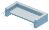 | Stacked prefab slab balcony | Complete prefab slab balcony |
 |  | |
| Slab Module Dataset | Dataset Name | Parameter Name | Value Type | Meaning of Parameters |
|---|---|---|---|---|
| Concrete Geometry Profile Dataset | BeamFloorBaseInfo | length | Double | Length of slab |
| width | Double | Width of slab | ||
| height | Double | Thickness of slab | ||
| depth | Double | Depth of slab end embedding | ||
| Rebar Overhang Direction Dataset | XRebarInfo | upperDiameter | Double | Diameter of upper rebar |
| upperDistance | Double | Spacing of upper rebar | ||
| downDiameter | Double | Diameter of lower rebar | ||
| downDistance | Double | Spacing of lower rebar | ||
| Rebar Vertical Direction Dataset | YRebarInfo | upperDiameter | Double | Diameter of upper rebar |
| upperDistance | Double | Spacing of upper rebar | ||
| downDiameter | Double | Diameter of lower rebar | ||
| downDistance | Double | Spacing of lower rebar |
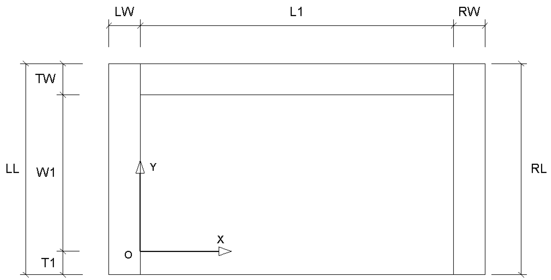
| Location (X, Y, Z) | Length | |
|---|---|---|
| Top edge beam | (0, W1, d1) | TL = L1 |
| Left overhanging beam | (0, W1, d1) | LL = TW + W1 + T1 |
| Right overhanging beam | (0, W1, d1) | RL = TW + W1 + T1 |
| Field | Serializes Object | Can It Be Null? |
|---|---|---|
| Floor ID | Number | No |
| Style | Beam/Slab | No |
| Slab | FloorBaseInfo | No |
| yRebarInfo | No | |
| XRebarInfo | No | |
| Top | TopBeamInfo | Yes |
| TopInfo | Yes | |
| Left | LeftBeamInfo | Yes |
| FbLeftInfo | Yes | |
| Right | RightBeamInfo | Yes |
| FbRightInfo | Yes | |
| Mid | MidBeamInfo | Yes |
| Type | Number of Components (PCS) | Number of Components That Can Be Generated (PCS) | Completion Rate (%) |
|---|---|---|---|
| Beam balcony | 2772 | 2607 | 94.04% |
| Slab balcony | 1004 | 905 | 90.14% |
| Total | 3776 | 3512 | 93.01% |
| Type | Number of Models Generated (PCS) | Number of Components That Can Read Data (PCS) | Data Readability Rate (%) |
|---|---|---|---|
| Beam balcony | 2607 | 2607 | 100% |
| Slab balcony | 905 | 905 | 100% |
| Total | 3512 | 3512 | 100% |
| Average Modeling Time of Beam Balcony (min) | Average Modeling Time of Slab Balcony (min) | |
|---|---|---|
| Traditional method | 22 | 18 |
| Data-driven modeling method | 5 | 4 |
| Time saving | 17 | 14 |
| LOD Accuracy Level | LOD100 | LOD200 | LOD300 | LOD350 | LOD400 | LOD500 |
|---|---|---|---|---|---|---|
| Conceptual Model | Approximate Geometry | Precise Geometry | Construction Documentation | Production and Construction Information | As Built | |
| Traditional method | √ | √ | √ | √ | × | × |
| Data-driven modeling method | √ | √ | √ | √ | √ | × |
Disclaimer/Publisher’s Note: The statements, opinions and data contained in all publications are solely those of the individual author(s) and contributor(s) and not of MDPI and/or the editor(s). MDPI and/or the editor(s) disclaim responsibility for any injury to people or property resulting from any ideas, methods, instructions or products referred to in the content. |
© 2023 by the authors. Licensee MDPI, Basel, Switzerland. This article is an open access article distributed under the terms and conditions of the Creative Commons Attribution (CC BY) license (https://creativecommons.org/licenses/by/4.0/).
Share and Cite
Cai, J.; Wang, X.; Shi, J.; Xie, X.; Feng, Y.; Wu, Y. Research on a Data-Driven Modeling Method for Precast Concrete Balcony Components. Buildings 2024, 14, 96. https://doi.org/10.3390/buildings14010096
Cai J, Wang X, Shi J, Xie X, Feng Y, Wu Y. Research on a Data-Driven Modeling Method for Precast Concrete Balcony Components. Buildings. 2024; 14(1):96. https://doi.org/10.3390/buildings14010096
Chicago/Turabian StyleCai, Jie, Xin Wang, Junfeng Shi, Xingxing Xie, Yu Feng, and Yingjun Wu. 2024. "Research on a Data-Driven Modeling Method for Precast Concrete Balcony Components" Buildings 14, no. 1: 96. https://doi.org/10.3390/buildings14010096
APA StyleCai, J., Wang, X., Shi, J., Xie, X., Feng, Y., & Wu, Y. (2024). Research on a Data-Driven Modeling Method for Precast Concrete Balcony Components. Buildings, 14(1), 96. https://doi.org/10.3390/buildings14010096