Abstract
In this investigation, a U-shaped connection (U-C) was introduced for a prefabricated steel plate shear wall with beam-only connections. This design replaces a portion of shear bolts with tension bolts to enhance bolt efficiency and reduce the overall bolt count, and it is suitable for a prefabricated high-rise steel structure. Four 1/3 scale specimens were designed, and an array of performance aspects including failure modes, hysteretic behavior, skeleton curves, energy dissipation capacity, stiffness degradation, and key performance indicators were systematically investigated through a combination of quasi-static tests and finite element analyses. The results showed that the combination arrangement of tensile and shear bolts in U-C effectively reduced the usage of bolts used and reduced installation costs; under low cycle reciprocating loads, the ultimate bearing capacity and energy dissipation capacity of a beam-only-connected prefabricated steel plate shear wall with U-shaped connection (BPSW-U) had slightly decreased compared with the prefabricated steel plate shear wall with discontinuous cover-plate connection (DCPC). Nevertheless, the BPSW-U excelled in preserving the integrity of the frame beams, channeling structural plastic deformations primarily into the infilled steel plate. This design feature ensures that post-earthquake functionality recovery can be achieved by simply replacing the infilled steel plate.
1. Introduction
Steel plate shear walls, as an innovative lateral-load-resisting structural system, are capable of assuming a substantial proportion of lateral loads within a structure. They effectively augment the initial lateral rigidity and horizontal load-bearing capacity of the structure. Functioning as a primary defense mechanism, these shear walls preclude damage to the main structural frame by intercepting and absorbing lateral forces prior to their impact [1,2,3,4,5]. Consequently, this mitigates the severity of damage sustained by the primary frame and elevates the structure’s resistance to collapse. This system comprises infilled steel plates and edge components, with the infilled steel plates being connectable to the edge components through either bolted or welded connections [6,7]. In order to better apply the steel plate shear wall system in prefabricated high-rise steel structures, the research on the prefabricated assembly connections between the infilled wall plates and edge components assumes paramount importance in comprehending their consequential influence on the structural lateral resistance.
In early research and engineering applications, the four-sided welded connection method was widely adopted to ensure the load transmission performance of the steel plate shear wall system [8,9,10,11,12,13,14]. Regrettably, this approach gave rise to an onerous challenge during on-site installations, marked by an excessive volume of welding activities, resulting in compromised weld quality, protracted construction timelines, and escalated structural expenditures. In response to these challenges, the increasing prevalence of bolted connections has emerged as a strategic response, aligning inherently with the characteristics of prefabricated steel structures.
Notably, in 1994, Xue [15,16] conducted a comprehensive analysis examining the ramifications of different connection methodologies between infilled wall panels and the surrounding framework on the mechanical performance of the steel plate shear wall system. The analysis proffered insights indicating that a configuration involving the connection of infilled wall panels on all four sides to the surrounding framework might induce premature failure of the framework columns due to forces exerted by the steel plates. Conversely, the adoption of a steel plate shear wall connected solely to the framework beams could avert premature column failure, albeit at the cost of a reduction in overall lateral stiffness. The utilization of steel plate shear walls connected on both sides presents a judicious compromise, effecting a discernible reduction in the number of connecting bolts, facilitating structural openings, and permitting ease of stiffness adjustments. Additionally, this approach mitigates the deleterious effects of steel plate shear wall buckling on columns.
In previous investigations [17,18,19], the author has effectively resolved part of challenges inherent in the bolted connections of steel plate shear walls, notably mitigating concerns pertaining to the phenomena of ‘unbuttoning’ and the amenability of ‘replaceability’ with respect to infilled steel plates. However, the considerable volume of bolts still poses heightened requirements for the precision of component fabrication at connection sites, thereby increasing both the temporal and economic costs of the engineering endeavor, while simultaneously augmenting the intricacy of construction. The question of whether it is possible to further diminish the quantity of bolts remains a critical inquiry, constituting one of the pivotal challenges for the extended applicability of prefabricated steel plate shear walls [20,21].
Therefore, this paper innovatively proposes a U-shaped connection for use in beam-only connected prefabricated steel plate shear wall structures (BPSW-U). This connection utilizes tensile bolts to replace the bolts between the cover plate and the beam flange, aiming to reduce the overall bolt usage. The seismic performance and post-earthquake reparability of this connection are studied through quasi-static tests, and a parametric performance analysis of the connection is conducted by establishing a finite element three-dimensional solid model.
2. Design Method for U-Shaped Connection
2.1. Construction
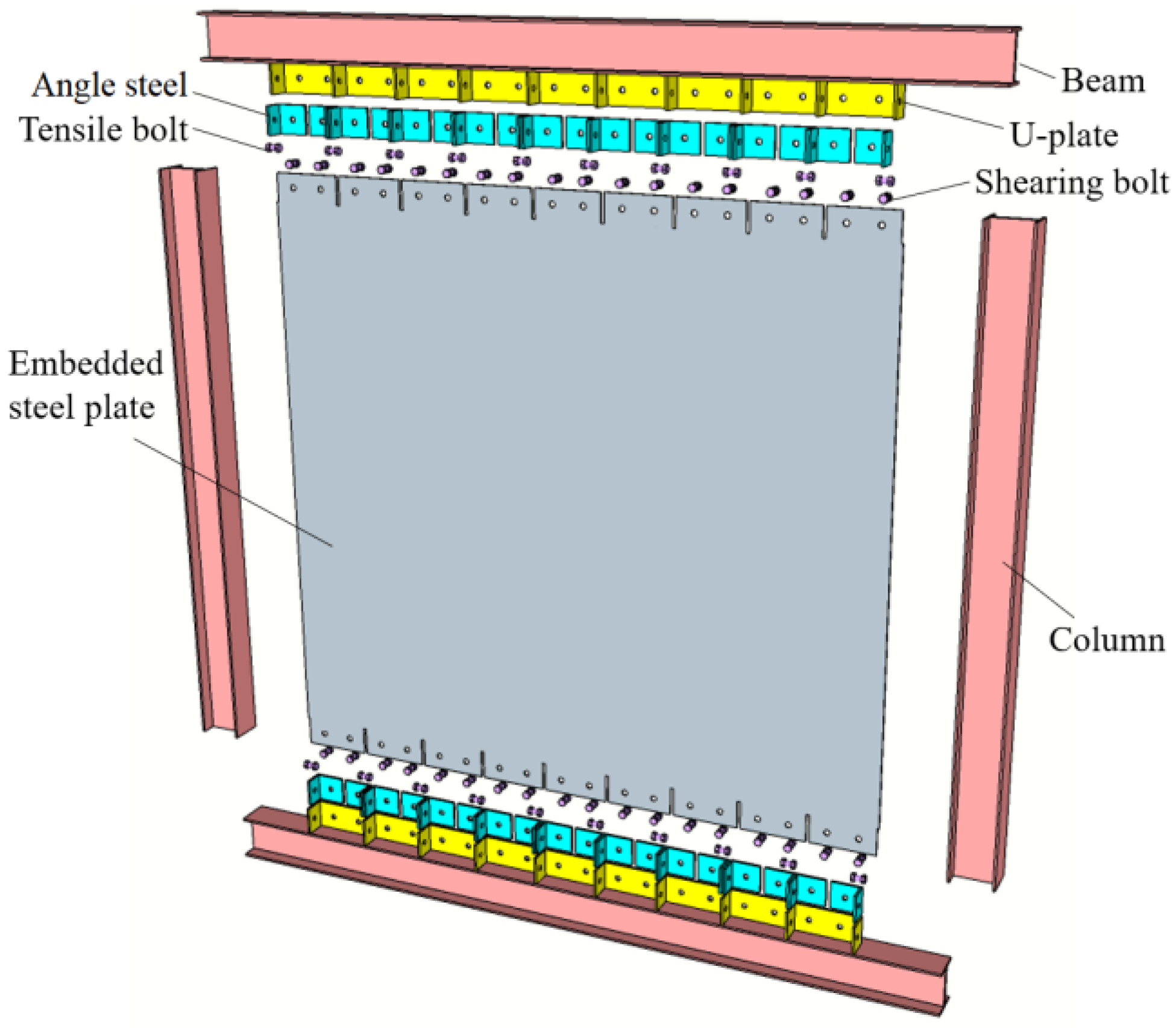
Figure 1 shows the splitting diagram of each part of the U-shaped connection (U-C), including frame beams, frame columns, U-shaped plates, infilled steel plate, connecting angle steels, and high-strength bolts. The frame beam was made of ordinary H-shaped steel welded with U-shaped plates at the bottom of the lower flange. There are two different forms of bolts in U-shaped connection, namely connection bolts between angle steel and an infilled wall panel (sheared bolts) and connection bolts between angle steel and a U-shaped plate (tensile bolts). The sheared bolts are high-strength bolts arranged perpendicular to the infilled plate, while tensile bolts are high-strength bolts arranged parallel to the infilled plate. The U-shaped plate in the connection was a perforated steel plate with multiple U-shaped grooves of equal dimensions. Bolt holes were provided on both flanges of the connecting angle steel. H-shaped steel columns were employed for the frame columns.

Figure 1.
Structural splitting diagram of U-shaped joint in prefabricated steel plate shear.
The steel plate shear walls, interconnected by this joint, enabled facile stiffness adjustments within the structure, while mitigating the impact of steel plate shear wall buckling on frame columns. To streamline U-shaped plate installation and circumvent potential challenges arising from processing errors, slotting treatment was applied to the infilled steel plate. Subsequently, large bolt holes, exceeding screw diameter by 4 mm, were incorporated into the infilled steel plate. Each shear bolt hole in the joint area corresponds to one angle steel, effectively minimizing cumulative errors resulting from the overall structure fabrication process.
Apart from the bolt holes on the infilled steel plate, all other openings maintain standard dimensions. U-shaped connection, in comparison to existing prefabricated joints, achieves a reduction in bolt usage without compromising structural stress performance. For instance, when contrasting U-C with DCPC joints [17], shear bolts in U-C correspond to the wall panel connection bolts in DCPC, while tensile bolts in U-C correspond to the beam flange connection bolts in DCPC. In U-C, shear bolts are primarily employed to resist wall panel slippage, whereas tensile bolts are used to prevent angle steel cover plate slippage. This configuration significantly reduces the number of bolts between the cover plate and the beam flange, ensuring that the angle steel remains secure during the joints’ stress process. It achieves a substantial 30% reduction in bolt utilization, thereby contributing to a reduction in overall installation costs.
2.2. Design Method
In 1983, Canadian scholar Thorburn [8] astutely identified the occurrence of the tension field effect following the buckling of the infilled wall panel. He emphasized that the bearing capacity of the wall panel post-buckling remained significant, thereby necessitating a departure from the earlier design criterion that relied on shear buckling stress. Subsequently, in the design and analysis of thin steel plate shear walls, the ultimate tensile strength of the tension field emerged as the new foundation for design considerations.
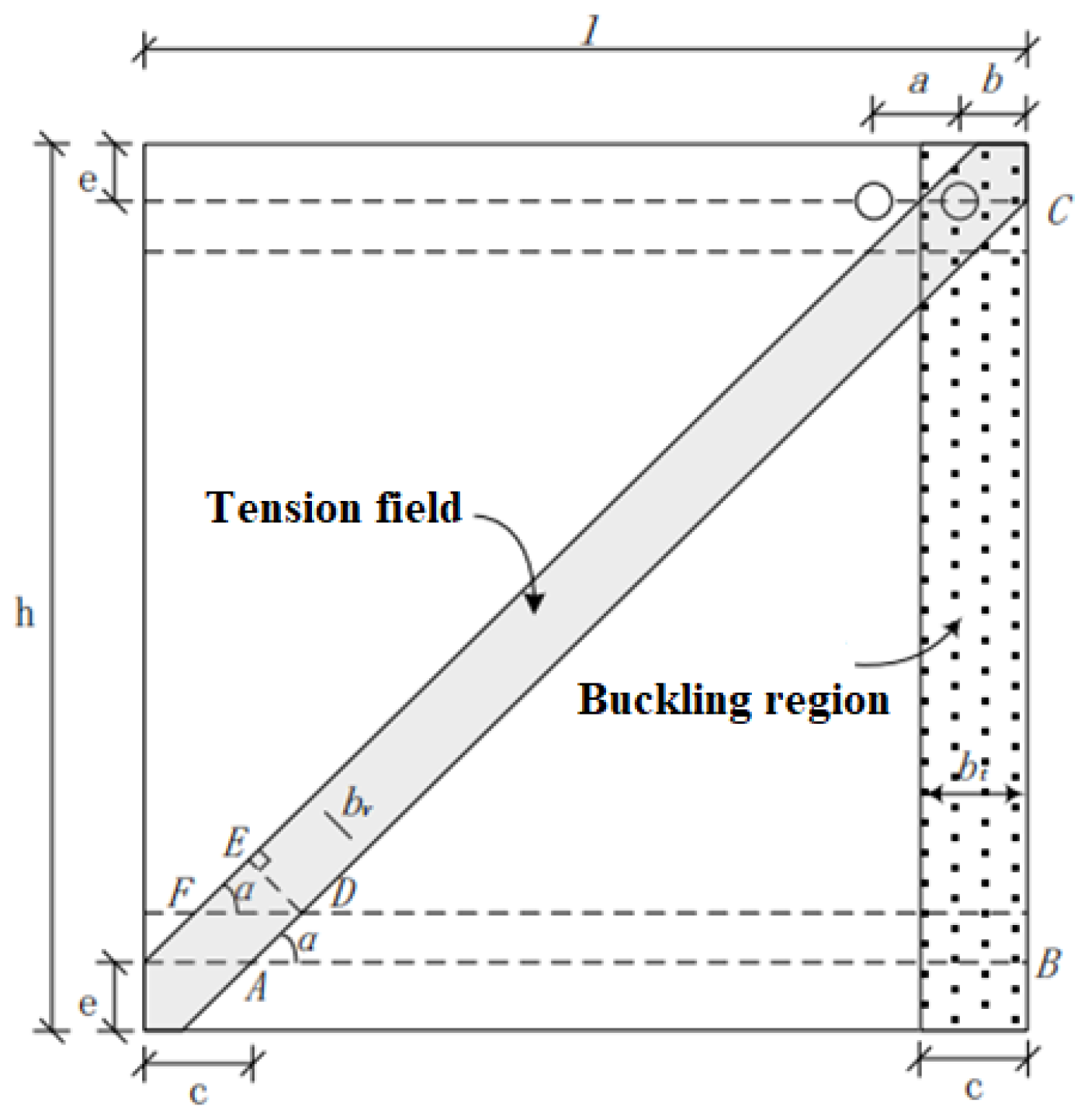
The U-shaped connection proposed in this chapter is meticulously devised to prevent slippage between the wall panel and the connecting angle steel and U-shaped plate. Therefore, it becomes imperative to ensure that the maximum shear force that a single high-strength bolt can sustain in the corner tension field surpasses the ultimate tensile strength of the tension field it supports. The calculation model for the joint design is depicted in Figure 2.
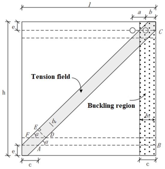
Figure 2.
Joint design calculation model.
- (1)
- Shear-resistant bolt design for the connection between the embedded steel plate and the U-shaped plate
Assuming the diameter of the large bolt holes opened on the infilled plate is d, the dimensions of the infill plate can be calculated using Equations (1)–(4):
where a is the spacing between the centers of bolt holes in a horizontal direction, see Figure 2; b is the end distance from the center of a bolt hole to the nearest edge of the infill plate in a horizontal direction, see Figure 2; c is the width of the buckling region, see Figure 2; d is the diameter of the bolt hole on the infilled plate; and e is the distance from the center of a bolt hole to the adjacent edge of the infill plate in a vertical direction, see Figure 2. These dimensions were determined according to the minimum design value required by the specification [22].
Angle between diagonal tension field and the horizontal plane α can be determined by Equations (5) and (6):
where bv,w is the width of the tension field resisted by a sheared bolt in the corner, see Figure 2.
The width of the tension field shared by the shear bolts in the shaded area of the diagram is:
The area of tension field shared by shear bolts is:
Ultimate tensile strength of the tension field shared by shear bolts is:
Due to the occurrence of out-of-plane buckling deformation in thin steel plates, corresponding out-of-plane loads are generated, and research has shown that this load can reach 10% of the yield strength of the steel plate. To avoid relative sliding of the steel plate due to insufficient bolt bearing capacity, the out-of-plane force generated by the buckling range of the steel plate shared by a single high-strength bolt is calculated during joint design:
In the Technical Specification for High Strength Bolt Connections of Steel Structures (JGJ82-2011), the design value of shear bearing capacity for friction-type high-strength bolts is:
where k1 is determined by the thickness of the connecting plate and it equals 0.9 when the connected plates are thicker than 6 mm; otherwise, it equals 0.8; k2 is determined by the type of the bolt hole and it equals 0.85 when the bolt hole is oversized; it equals 1 when bolt hole is normal; nf is the number of the friction surfaces, since the sheared bolt connection uses the angle steel and the U-shaped plate to clamp the infilled plate; nf is taken as 2; μ is the friction coefficient; and P is the pre-tightening force of the bolt. Then, Equation (11) can be simplified and written as:
The design value of tensile strength for friction-type high-strength bolts is:
The bearing capacity of friction-type high-strength bolts under the combined action of tension and shear should meet the following requirements [22]:
where i is the design criteria coefficient.
- (2)
- Tension-resistant bolt design for the connection between the angle steel and the U-shaped plate.
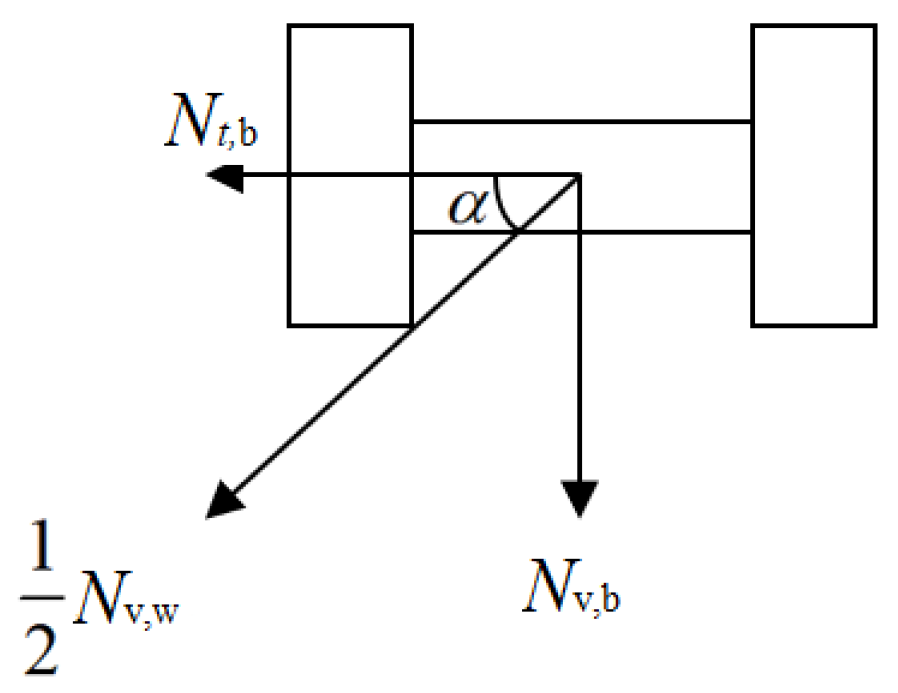
Through a force analysis, it is discerned that the internal forces generated within the tension field will be collectively transmitted by both the shear-resistant bolt connection and the tension-resistant bolt connection to the U-shaped connection plate welded onto the beam. Assuming an equitable distribution of 50% internal forces to each type of bolt connection within the tension band, as shown in Figure 3, the design of the tension-resistant bolts can be executed using the subsequent equations.
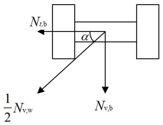
Figure 3.
Schematic diagram of force decomposition for tensile bolts.
The shear carrying capacity design value of the corner tensile bolt can be calculated using Equation (17), as there is only one friction surface at the connection of the tensile bolt.
The design value of tensile bearing capacity of tensile bolts is:
Under the combined action of tension and shear, the bearing capacity of tensile bolts should meet the following requirements:
3. Specimens Design
3.1. Specimen Size
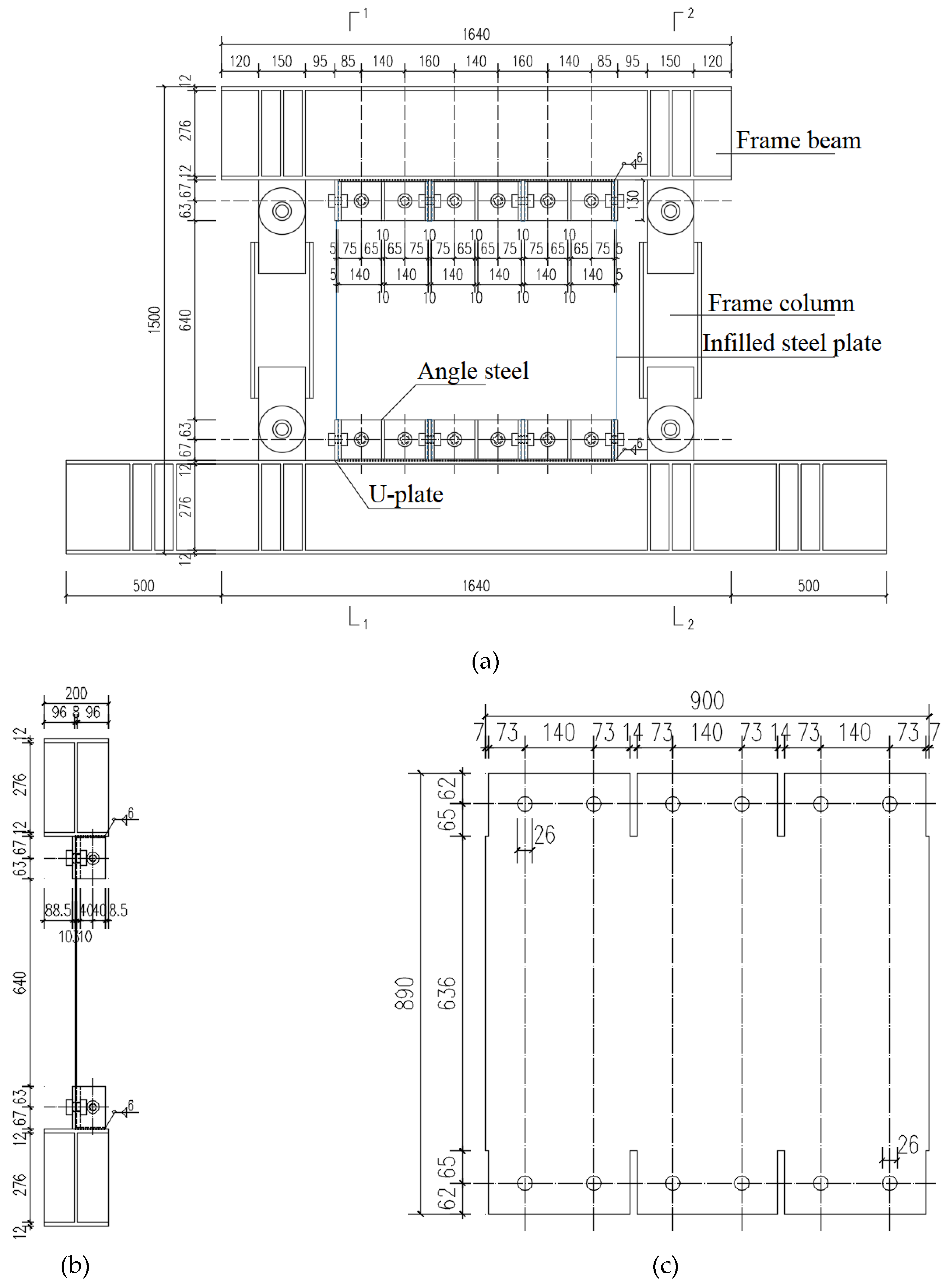
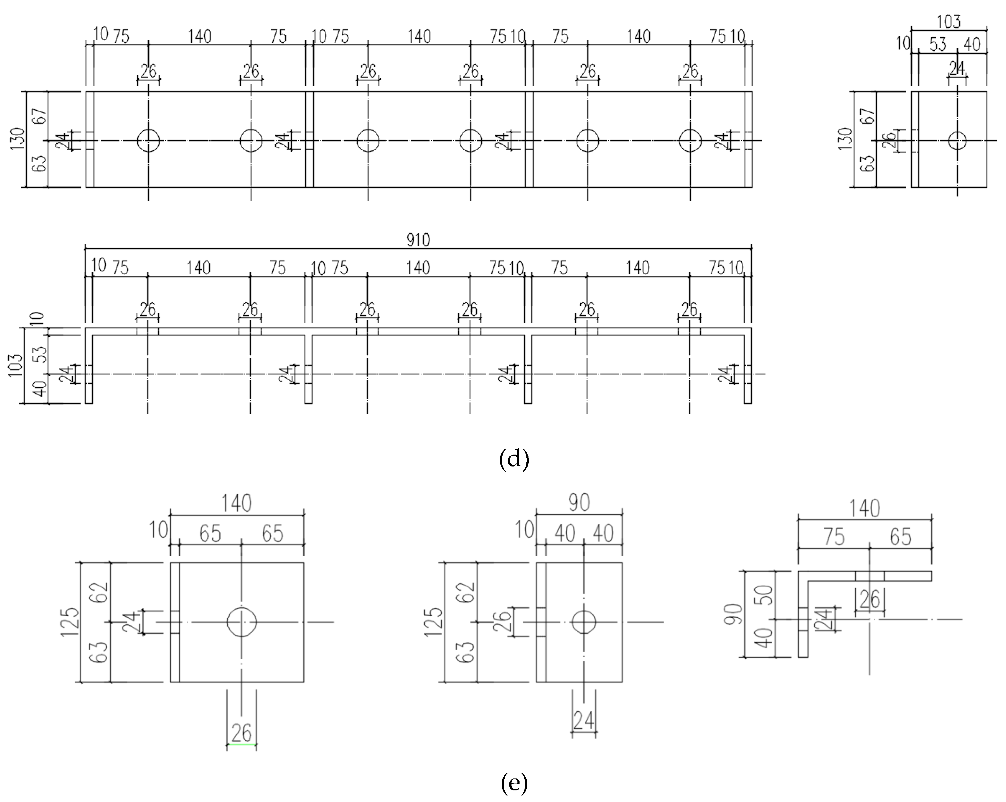
Due to constraints imposed by the experimental apparatus and conditions, it is imperative to employ reduced-scale specimens for this investigation. Adhering to the design methodology employed for DCPC joint test specimens [17], this study has elected to utilize 1/3 scale models for quasi-static testing. This choice facilitates a systematic post-experimental comparison of data and performance metrics between the two distinct joint configurations. The detailed dimensions of four steel plate shear wall specimens with U-shaped connections are shown in Table 1. The table includes the dimensions of the steel plates, the diameters of the tensile bolts, and the shear bolts. Ordinary H-shaped steel is used for both frame beams and hinge columns, with cross-sectional dimensions of H200 × 300 × 8 × 12 and H200 × 200 × 8 × 12, respectively. The steel grade for the frame beams and hinge columns is Q355, while the rest of the components are made of Q235. High-strength bolts of grade 10.9 are used for the connections. The schematic diagram for the specimen is shown in Figure 4.

Table 1.
Detailed dimension of the specimens.
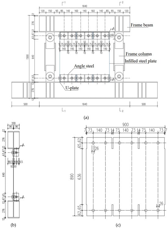
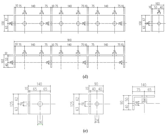
Figure 4.
Details of specimen. (a) Front view of the specimen; (b) side view of the specimen; (c) embedded steel plate; (d) U-shaped plate; (e) Angle steel.
3.2. Material Properties
Based on different steel grades and thicknesses, the steel used for four specimens was categorized into five groups, with three samples taken from each group [23,24]. These were subjected to material properties test, and the results are shown in Table 2.
Table 2.
Material test results.
3.3. Loading Device and Protocol
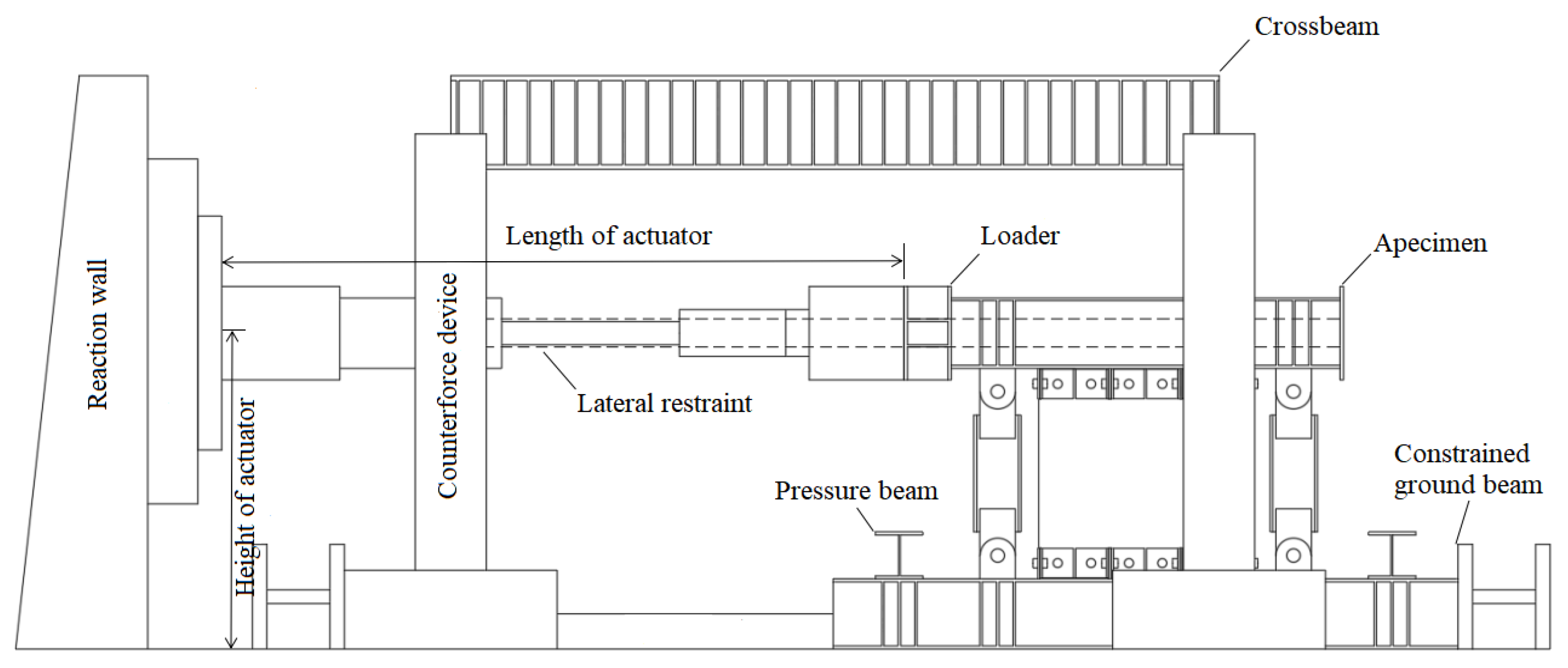
The experiment employed a hydraulic servo system to apply low-cycle reciprocating loads under displacement control throughout the test. Horizontal loads were generated by an MTS 150 t tension-compression actuator connected to one end of the top beam. Lateral constraint beams, affixed to the reaction frame on both sides of the upper beam, were introduced to prevent any out-of-plane displacement during the loading process. Horizontal and vertical restraint beams were positioned at both ends of the bottom beam to constrain its displacement. The loading devices are illustrated in Figure 5 and Figure 6. The loading protocol is the low-cycle reciprocating loading in accordance with the AISC 341–16, and the loading protocol is shown in Figure 7.
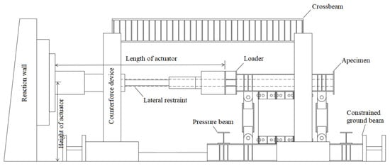
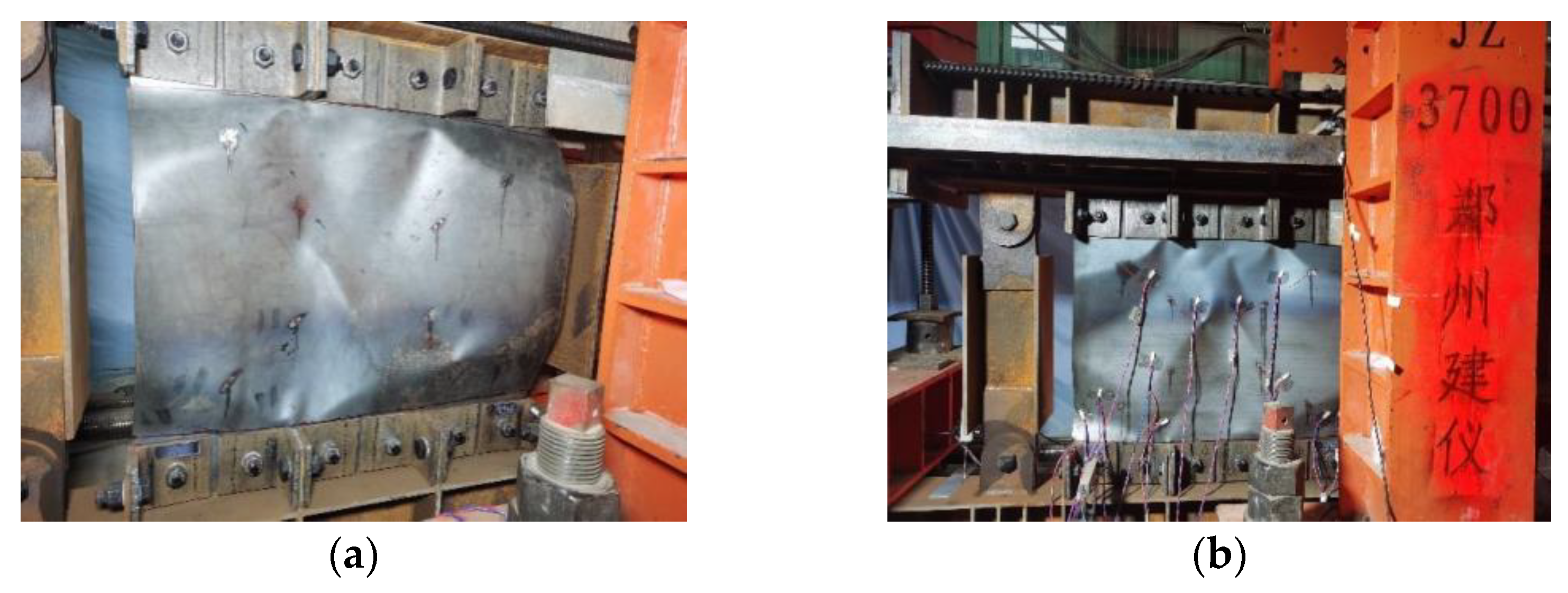
Figure 5.
Loading device diagram.

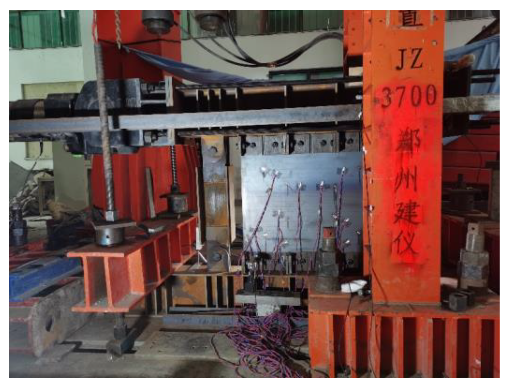
Figure 6.
Test loading device.
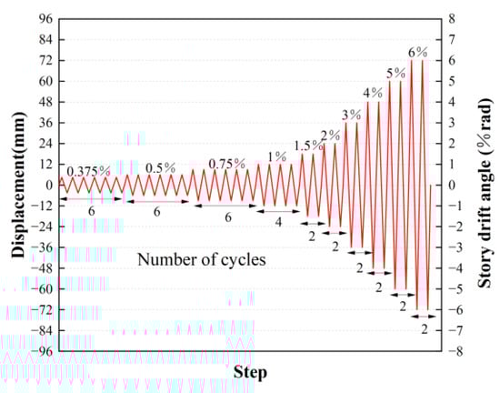
Figure 7.
Loading protocol.
3.4. Experiment Process
By observing the strain gauge data, it can be inferred that, at the first loading level of the test, corresponding to an inter-story drift angle of ±0.375%, all the specimens remained within the elastic stage. No sliding occurred in the connection region and there was no evidence of buckling in the infilled steel plates.
When entering the third loading level, corresponding to an inter-story drift angle of ±0.75%, slight buckling deformations were observed in the infilled steel plates of all four specimens during the loading process, accompanied by continuous and mild buckling sounds. At this point, the degree of buckling in U-4 was noticeably smaller than in the other specimens.
Upon reaching the fourth loading level, with an inter-story drift angle of ±1%, alternating tension bands appeared in the embedded wall panels, forming distinct creases on the panels. As the inter-story drift angle increases, the deformation of the steel plate became more severe, making the bending sound emitted by the steel plate more pronounced. At this time, it could be observed that there was significant sliding of the infilled steel plate at the connection area. Notably, U-1, U-2, and U-3 exhibited more significant buckling and creases due to their thinner embedded wall panels. U-4 showed the most pronounced sliding at the connection joints, while U-3 exhibited the smallest sliding at the connection joints. This is attributed to the larger diameter of the shear-resistant connection bolts in U-3, resulting in higher pretension forces during installation and consequently greater frictional resistance between the joint plates. The thicker embedded wall panels in U-4, coupled with larger internal forces within the tension bands at the same displacement, facilitated overcoming frictional forces, leading to more apparent sliding.
In the sixth loading level, corresponding to an inter-story drift angle of ±2%, the degree of buckling in the embedded wall panels continued to increase, and creases became more pronounced. However, there was no noticeable deformation in the angle steel cover plates, U-shaped base plates, and edge beams at the joints for all specimens. Strain readings indicated that these components remained in the elastic range and exhibited no displacement. U-1 and U-2 showed slight tearing at the locations of the wall panel openings. This is attributed to the thinner wall panels in these two specimens and the smaller shear-resistant connection bolts, resulting in significant alternating sliding of the wall panels in the connection region, leading to repeated buckling and subsequent tearing of the steel plates.
After the conclusion of the seventh loading level, with an inter-story drift angle reaching ±3%, U-3 exhibited significant tearing at the openings in the embedded wall panels. The experiment concluded after the ninth loading level, corresponding to an inter-story drift angle of ±5%, as U-1, U-2, and U-3 exhibited severe out-of-plane buckling deformation in the infilled steel plates, necessitating termination of the test for safety reasons. However, U-4 continued to withstand loading and concluded the experiment after the tenth loading level, with an inter-story drift angle reaching ±6%.
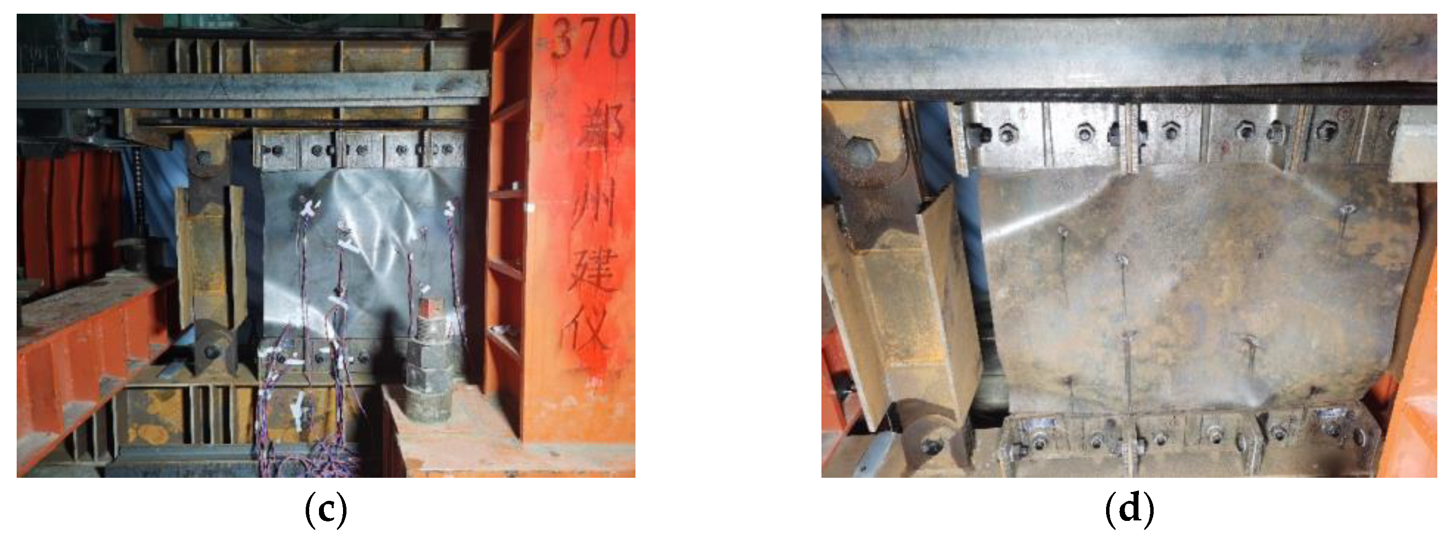
After unloading following the completion of the loading phases, the observed failure modes of the components are depicted in Figure 8. After the experiment, all parts of the specimen were disassembled and it was observed that frame beams, U-shaped connection plates in the connection region, and angle steels did not exhibit significant deformation. The bolt holes in these components also showed no noticeable deformation. Severe damage was limited to the infilled wall panels. This indicates that the BPSW-U effectively protects the main frame and connection regions. Post-earthquake functionality can be easily restored by simply replacing the infilled wall panels.
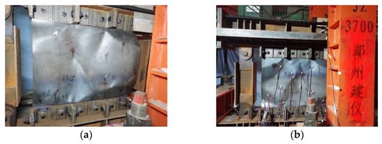
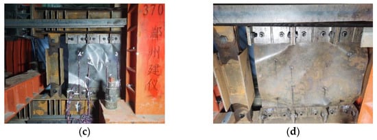
Figure 8.
Failure modes of specimens. (a) U-1; (b) U-2; (c) U-3; (d) U-4.
3.5. Analysis of Test Results
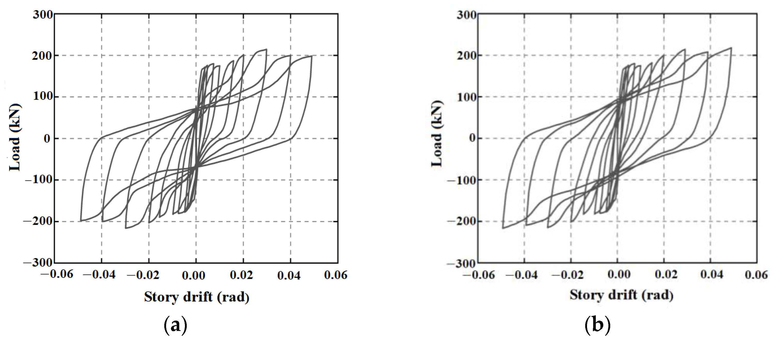
3.5.1. Hysteretic Behavior
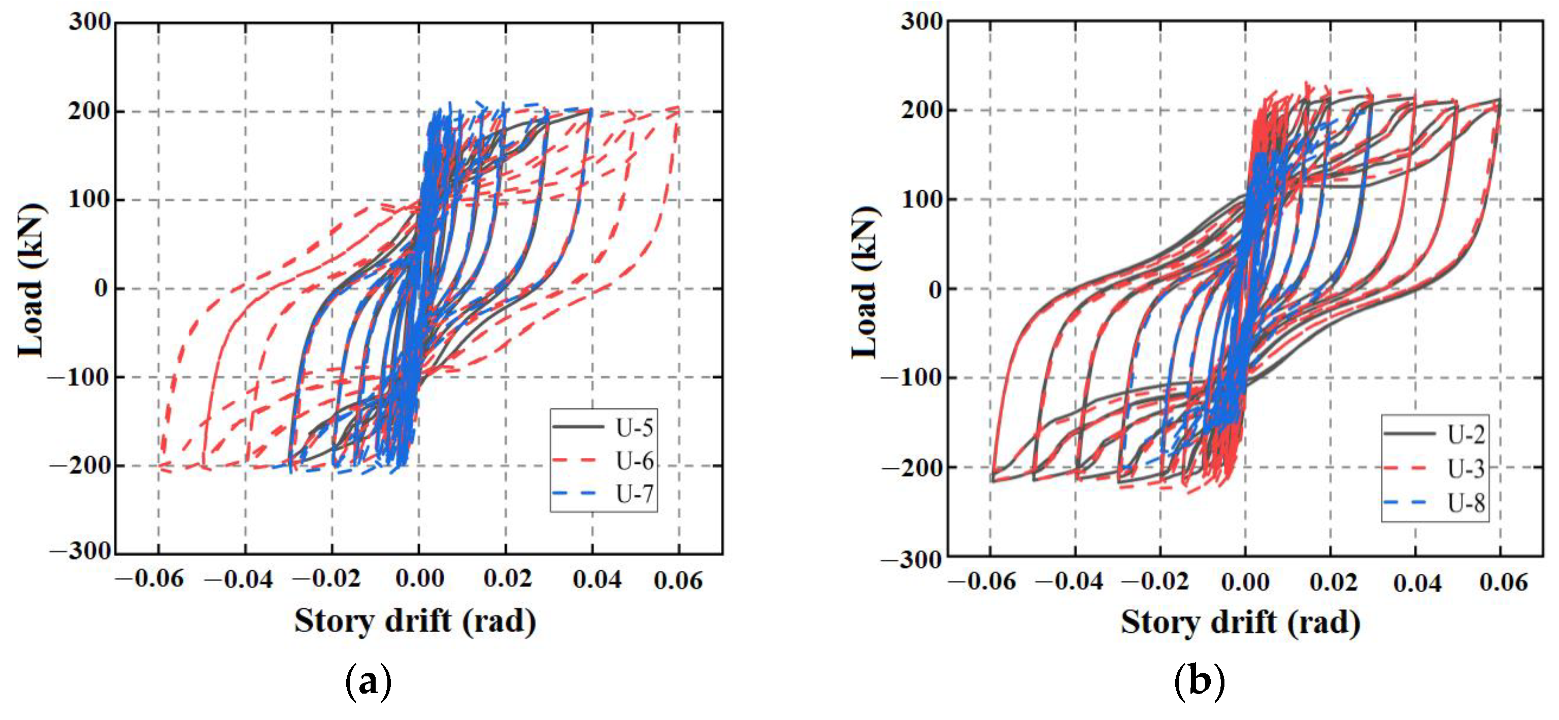
The hysteresis curves of the four specimens are shown in Figure 9. A comprehensive comparative analysis reveals the following trends: the hysteresis curves of specimens U-1 and U-2 exhibit a remarkable degree of similarity, with U-3 presenting a slightly plumper hysteresis response compared to the former two. Remarkably, the hysteresis curve of U-4 appears the plumpest. This is attributed to U-1 and U-2 both utilizing Grade 10.9 high-strength bolts with a diameter of 20 mm as shear-resistant bolts. The frictional forces between the embedded wall panels and cover plates in the nodal region are the same for both specimens, and both specimens use 3 mm thick steel plates as embedded wall panels. The only difference between U-1 and U-2 is the diameter of the tensile bolts, and their hysteresis performance was equivalent. This indicated that the tensile bolts only needed to meet the requirements of Equation (19). Once this requirement is met, increasing the diameter or quantity of the tensile bolts does not have a significant impact on the hysteresis performance of the joint. The variation in tensile bolts has little impact on the hysteresis performance of specimens U-1 and U-2. Increasing the diameter of the shear-resistant bolts and consequently increasing the frictional forces between the embedded wall panels and cover plates in the nodal region is beneficial in delaying the sliding of the embedded wall panels in the nodal region, thereby postponing pinching in the hysteresis curve. This is because frictional forces can also provide a certain amount of energy dissipation capacity for the prefabricated steel plate shear wall. Changing the wall panel thickness significantly enhances the ultimate load-carrying capacity of the specimens and the fullness of the hysteresis curve. However, it has little effect on the bolt sliding time.
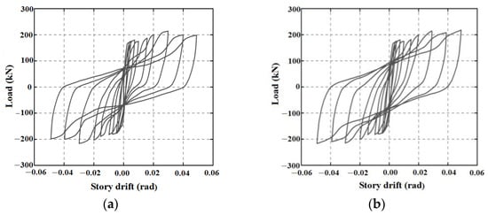
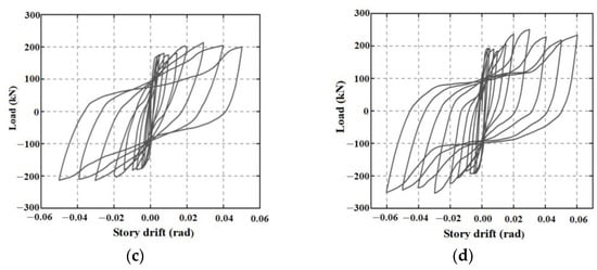
Figure 9.
Hysteretic curves. (a) U-1; (b) U-2; (c) U-3; (d) U-4.
3.5.2. Skeleton Curve and Performance Index
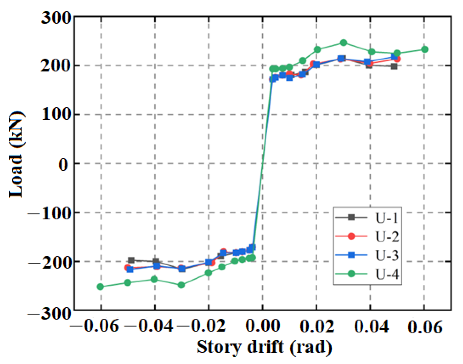
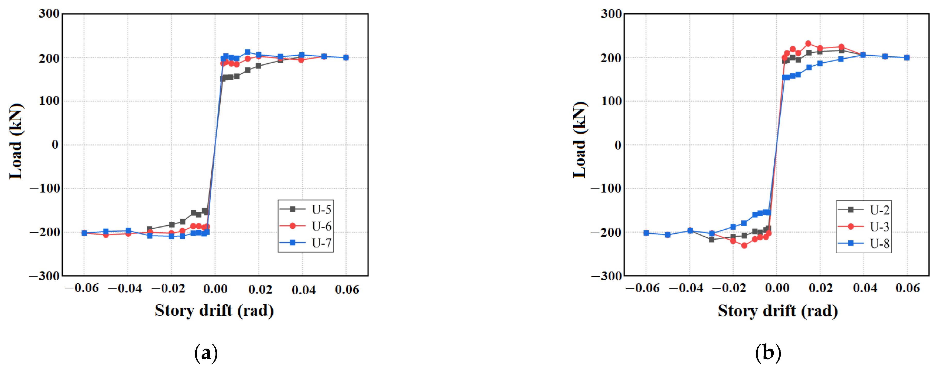
The skeleton curves of the four specimens are extracted and illustrated in Figure 10. Analysis reveals that the skeleton curves of specimens U-1, U-2, and U-3 closely coincide, exhibiting nearly identical initial stiffness. As the specimens enter the elastic–plastic stage, the skeleton curves gradually flatten. All specimens reach ultimate load at the seventh loading level (inter-story drift angle of 3%), and their bearing capacities experience a slight decrease thereafter; the load-bearing capacities do not drop below 85% of the ultimate load until the end of the test, indicating excellent ductility. Notably, due to the thicker infilled wall panels in specimen U-4, its ultimate load is significantly higher than the other three specimens. After the eighth loading level (inter-story drift angle of 4%), specimens U-1, U-2, and U-3 exhibited tearing at the wall panel openings, leading to slight differences in the skeleton curves during the final two loading levels.
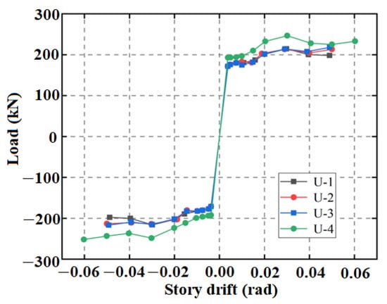
Figure 10.
Skeleton curves of the specimens.
The primary performance indicators of the four specimens are extracted, as shown in Table 3. Due to the thicker infilled steel plates in specimen U-4, this specimen exhibits significantly higher initial stiffness and ductility factor than the other three specimens. The ultimate load capacity of specimen U-3 is slightly higher than that of U-1 and U-2, indicating that increasing the frictional forces between the infilled wall panels and connecting plates can enhance the ultimate load capacity of the specimen, albeit with limited magnitude. The ductility factors of all specimens are greater than 7, indicating excellent ductility of BPSW-U. The enlargement of the diameter of the tensile bolts imparts a negligible influence on the load-bearing capacity and ductility of the specimens.
Table 3.
Primary performance indicators of the specimens.
3.5.3. Energy Dissipation
By calculating the enveloping area of the hysteresis curve for each specimen at every loading level, the obtained values represent the energy dissipated by the specimens at that loading level, as shown in Figure 11. Overall, due to the utilization of thicker infilled steel plates, specimen U-4 demonstrates progressively superior energy dissipation capabilities with increasing inter-story drift compared to the other three specimens. In the initial four loading levels, specimens U-1, U-2, and U-3 exhibit similar energy dissipation capacities. In the fifth loading level, the larger diameter of the shear-resistant bolts in U-3 results in greater frictional forces between the infilled wall panel and connecting plates, consequently providing more significant energy dissipation due to bolt sliding than the other three specimens. However, as the coefficient of friction on the contact surface noticeably decreases with an increasing number of sliding cycles, the subsequent loading levels do not manifest the advantage of sliding-induced energy dissipation.
Figure 11.
Energy dissipation of the specimens.
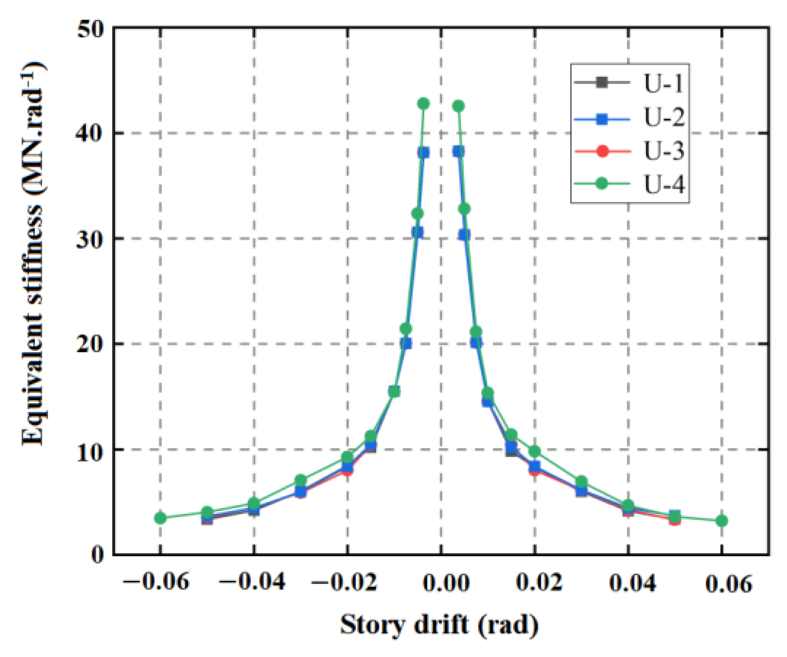
3.5.4. Stiffness Degradation
The equivalent stiffness of each specimen is extracted to generate equivalent stiffness degradation curves, as shown in Figure 12. The positive and negative stiffness degradation curves for all four specimens exhibit a pronounced symmetry. Specimen U-4, characterized by a higher initial stiffness, experiences the fastest rate of stiffness degradation, reaching only 8% of its initial stiffness at the end of the test. The stiffness degradation curves for specimens U-1, U-2, and U-3 closely coincide, suggesting that altering the diameter of the connecting bolts has no discernible impact on the initial stiffness and stiffness degradation of the specimens.

Figure 12.
Stiffness degradation curve of the specimens.
4. Finite Element Analysis
4.1. Finite Element Model
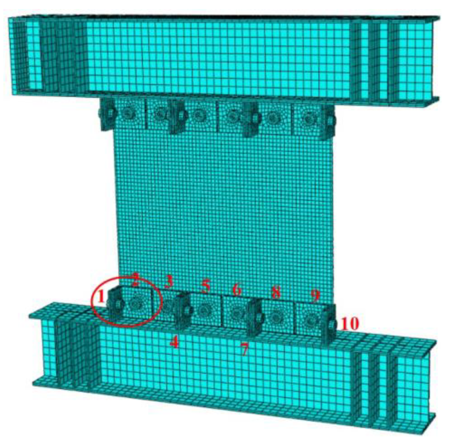
The Finite Element Model (FEM) of the U-shaped connection is established using ABAQUS, as illustrated in Figure 13. The red numbers in the figure are bolt numbers. Bolts 1,4,7, and 10 are tensile bolts. Bolts 2,3,5,6,8, and 9 are shear bolts. The FEM’s detailed dimensions mirror those of the physical specimens. Given that the experimental components featured hinged columns, the frame columns were simplified accordingly in the FEM [17]. With the exception of the rigid pad at the loading point, all other components are modeled based on the solid model, utilizing C3D8R as the model element. The friction coefficient between bolts and various components is taken as 0.05, and the friction coefficient of the contact surfaces between other components is taken as 0.25. Recognizing the elevated stress at the connection between the infilled steel plate and the frame beam, the mesh density is appropriately increased at the corresponding position in the model. In the case of U-2 and U-4, only the thickness of the infilled steel plate was modified in the modeling process. Specimens U-1 and U-3 exhibit distinct diameters for the tensile and shear bolts, while the dimensions of the other components remain consistent. The loading protocol for the finite element simulation is consistent with the quasi-static test.

Figure 13.
Finite element model.
4.2. Analysis Results of the FEM
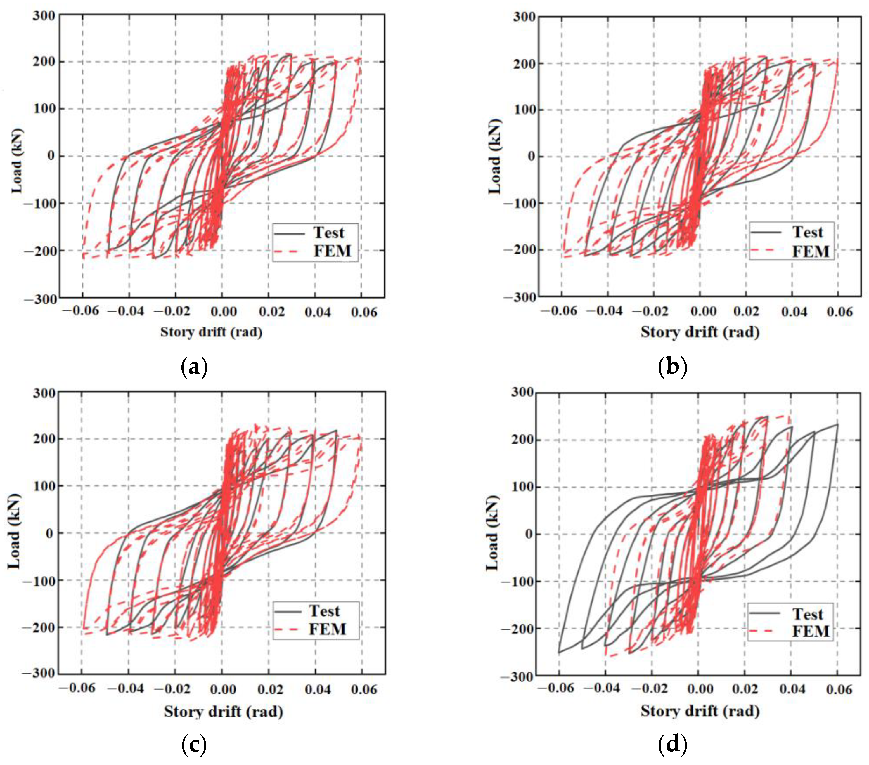
4.2.1. Comparison of Hysteretic Behavior and Failure Modes
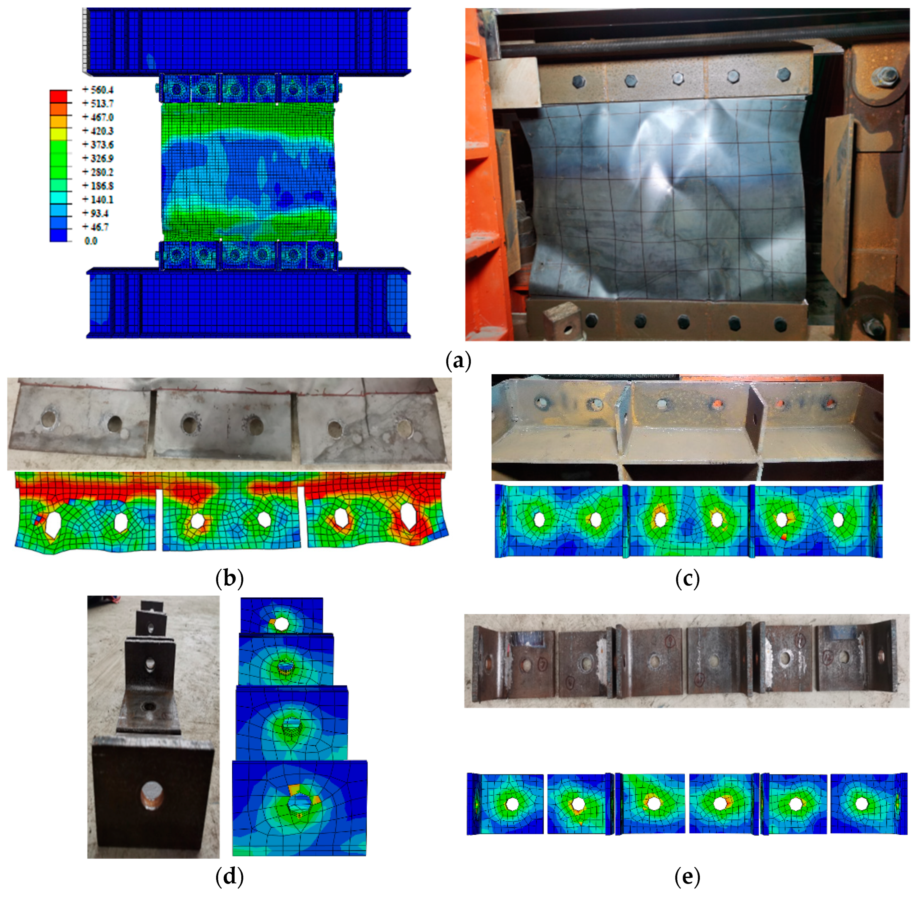
As shown in Figure 14, the red dashed lines correspond to the hysteresis curves obtained through finite element simulation for the four specimens. A comparison with experimental data reveals excellent agreement between the finite element simulation results and the experimental outcomes. Figure 15 provides a comparative illustration of the failure modes between the experimental and finite element models, demonstrating an excellent agreement between the two. Thus, the reliability of the finite element modeling is validated.
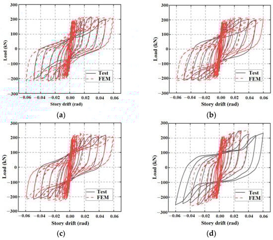
Figure 14.
Hysteretic curves comparison. (a) U-1; (b) U-2; (c) U-3; (d) U-4.

Figure 15.
Comparison between test and finite element failure mode of specimen U-2. (a) The entire wall panel; (b) infilled steel plate; (c) U-shaped plate; (d) the side of the angle steel; (e) the front of the angle steel.
Analyzing the stress distribution obtained from the finite element simulation for the specimens, it is observed that the stress in the frame beams remains relatively low and consistently in the elastic range. The U-C joint can decompose the internal forces within the infilled steel plate tension field into components parallel and perpendicular to the beam. The force component parallel to the beam is primarily borne by the weld between the U-shaped bottom plate and the beam. Meanwhile, the force component perpendicular to the beam is shared by both the beam and the U-shaped bottom plate. In this configuration, the U-shaped bottom plate also acts as a reinforcement for the beam against bending, resulting in reduced internal stresses within the beam. The stresses in the U-shaped connection plates and all angle steel connection plates are slightly higher but do not reach their yield strength, indicating that these components also remain in the elastic range. In contrast, severe damage is observed in the infilled steel plates, particularly at the steel plate openings and the corners of bolt holes, where stress concentration and deformation are pronounced. This underscores the role of the embedded steel plate as the sole yielding energy-dissipating component in BPSW-U, demonstrating that post-earthquake functionality recovery of the structure can be achieved by simply replacing the infilled wall panel.
4.2.2. Bolt Participation Analysis
To investigate the influence of bolts with different dimensions on the seismic performance of BPSW-U, the following models were established using the finite element software Abaqus, with model dimensions listed in Table 4, Figure 16 and Figure 17.
Table 4.
Finite element model dimensions.
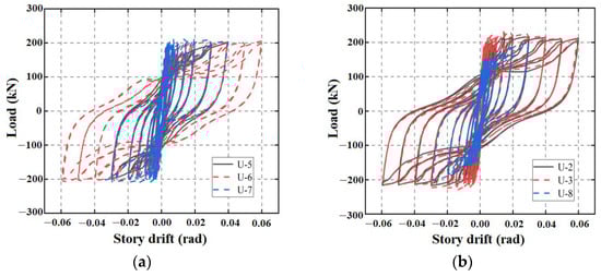
Figure 16.
Hysteretic curves of FEM results. (a) Group A; (b) Group B.
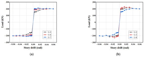
Figure 17.
Skeleton curves of FEM results. (a) Group A; (b) Group B.
Extracted from finite element simulations, the initial pretension force, residual pretension force, and pretension force loss rate of corner bolt 1 and 2 were analyzed for all specimens except U-4. The findings, as outlined in Table 5, reveal that the pretension force loss for corner tensile bolts (Bolt 1) remains below 10%, primarily attributed to the slip of the embedded steel plate. Conversely, the corner shear bolts (Bolt 2) exhibit pretension force losses exceeding 50%, as these bolts not only bear the slip load of the infilled steel plate but also resist the out-of-plane deformation resulting from the buckling of the infilled steel plate. Consequently, in bolt connection design, it is recommended to judiciously reduce the diameter and quantity of tensile bolts.
Table 5.
Bolt pretension force loss.
4.3. Comparison between U-C and DCPC
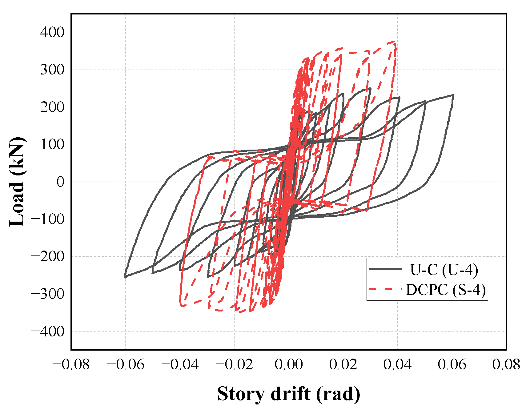
A comparison between the experimental results of the U-C (U-4) and the DCPC (S-4) [17] is presented in Figure 18. Analysis indicates that, with the use of identical-sized infilled steel plates, the DCPC exhibits higher ultimate bearing capacity. However, its hysteresis curve shows more pronounced pinching, while the U-C’s hysteresis curve is plumper. The initial stiffness of the two is essentially the same. Regarding the failure mode, in the last few loading levels, the DCPC shows slight irreversible deformation in the frame beam, whereas the U-C effectively protects the frame beam, thereby enhancing the seismic recovery performance of BPSW-U.
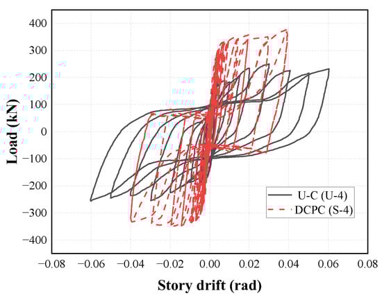
Figure 18.
Comparison of hysteretic curves between U-C and DCPC.
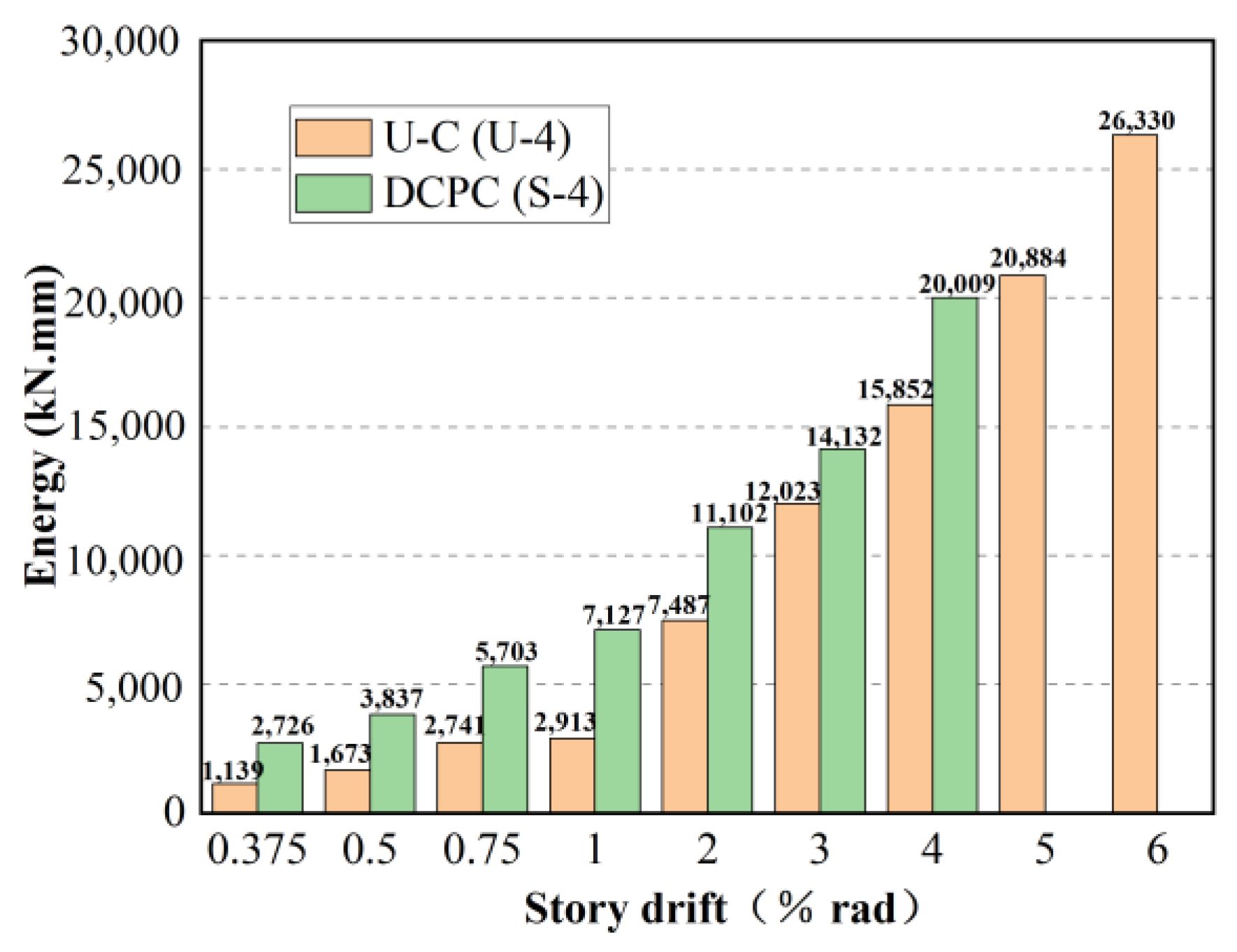
By computing the enveloping area of the hysteretic curves, the energy dissipation for both entities is determined, as shown in Figure 19. Analysis indicates that the energy dissipation capacity of DCPC exceeds that of the U-C; however, with the augmentation of the inter-story displacement angle, the distinction in their energy dissipation performances gradually diminishes. The energy dissipation capacity of DCPC exceeds that of U-C for two main reasons. Firstly, the shear bolt quantity in DCPC joint specimens is 1.5 times that of U-C, resulting in a delayed wall panel sliding. Secondly, in U-C joints, notches are introduced in the embedded steel plate to meet installation requirements, significantly reducing the shear-carrying capacity of the embedded steel plate. Nevertheless, as the inter-story displacement increases, the comprehensive development of the tension band contributes to partially compensating for this attenuation.
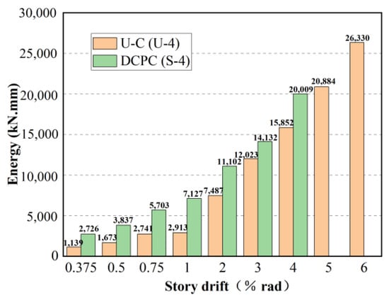
Figure 19.
Comparison of energy dissipation between U-C and DCPC.
5. Conclusions
In this paper, a beam-only-connected prefabricated steel plate shear wall with U-shaped connection (BPSW-U) was proposed. This design replaces some shear bolts with tension bolts to improve bolt efficiency and reduce the amount of usage of bolts, and it is suitable for a prefabricated high-rise steel structure. Four 1/3 scale specimens were designed, and the failure modes, hysteretic behavior, skeleton curve, energy dissipation capacity, stiffness degradation, and key performance indicators were obtained by quasi-static tests and finite element analyses on the specimens. The primary conclusions are as follows:
- The hysteresis curve of BPSW-U is relatively plump, exhibiting good symmetry in stiffness degradation and excellent component ductility. Under low-cycle reciprocating loads, noticeable sliding occurs at the corner connections of the infilled steel plate, and severe buckling of the infilled steel plate is observed. Beyond an inter-story displacement angle of 2%, cracking gradually appears at the infilled steel plate opening due to stress concentration.
- In the BPSW-U, the strength of shear bolts plays a crucial role in influencing the sliding load capacity. To ensure yielding precedes sliding, it is imperative to augment the diameter or quantity of shear bolts.
- The influence of tensile bolts on the seismic performance of BPSW-U is relatively minor. Therefore, in the design of bolt connections, it is feasible to minimize the quantity of tensile bolts or reduce their diameter, thereby reducing construction complexity and cost.
- Compared to the DCPC joint, BPSW-U can more effectively safeguard the frame beam and connecting plate. It allows for a better concentration of plastic deformation in the infilled steel plate, enabling easy restoration post-earthquake by simply replacing the infilled steel plate. Additionally, the full prefabricated connection adopted by BPSW-U facilitates straightforward disassembly and installation during repairs.
Author Contributions
Conceptualization, X.Z. and Q.L.; methodology, X.Z. and Q.L.; software, Q.L., X.Z., and F.Y.; validation, W.X. and Q.L.; formal analysis, X.Z.; investigation, W.X. and L.C.; resources, X.Z.; data curation, F.Y.; writing—original draft preparation, Q.L.; writing—review and editing, X.Z.; visualization, W.X.; supervision, L.C.; project administration, L.S.; funding acquisition, X.Z. All authors have read and agreed to the published version of the manuscript.
Funding
This research was funded by The Postdoctoral Research Grant in Henan Province, Grant number 202103010.
Data Availability Statement
All relevant data is within the paper.
Conflicts of Interest
Author Liming Cai was employed by the company The Architectural Design and Research Institute of Henan Province Co., Ltd., and Lianzhi Song was employed by the company The Architectural Design and Research Institute of Henan Province Co., Ltd. The remaining authors declare that the research was conducted in the absence of any commercial or financial relationships that could be construed as a potential conflict of interest.
References
- Roberts, T.; Sabouri-Ghomi, S. Hysteretic characteristics of unstiffened perforated steel plate shear panels. Thin. Wall. Struct. 1992, 14, 139–151. [Google Scholar] [CrossRef]
- Vincent, C.; Elgaaly, M.; Chen, R. Experimental study of thin steel-plate shear walls under cyclic load. J. Struct. Eng. 1993, 119, 573–587. [Google Scholar]
- Mohamed, E. Thin steel plate shear walls behavior and analysis. Thin. Wall. Struct. 1998, 32, 151–180. [Google Scholar]
- Lubell, A.S.; Prion, H.G.L.; Ventura, C.E.; Rezai, M. Unstiffened steel plate shear wall performance under cyclic loading. J. Struct. Eng. 2000, 126, 453–460. [Google Scholar] [CrossRef]
- Bing, Q.; Bruneau, M. Design of steel plate shear walls considering boundary frame moment resisting action. J. Struct. Eng. 2009, 135, 1511–1521. [Google Scholar]
- Zhang, A. The key issues of system innovation, drawing up standard and industrialization for modularized prefabricated high-rise steel structures. Ind. Constr. 2014, 44, 1–6. [Google Scholar]
- Guo, Y.; Zhou, M. Categorization and performance of steel plate shear wall. J. Arch Civ. Eng. 2009, 26, 1–13. [Google Scholar]
- Thorburn, L.; Kulak, G.; Montgomery, C. Analysis of Steel Plate Shear Walls; Structural Engineering Report; Department of Civil and Environmental Engineering, University of Alberta: Edmonton, AB, Canada, 1983. [Google Scholar]
- Driver, R. Cyclic test of four-story steel plate shear wall. J. Struct. Eng. 1998, 124, 112–120. [Google Scholar] [CrossRef]
- Chen, G.; Guo, Y. Ultimate shear-carrying capacity of unstiffened panels. Eng. Mech. 2003, 20, 49–54. [Google Scholar]
- Sabouri-Ghomi, S.; Gholhakia, M. Ductility of thin steel plate shear walls. Asian J. Civ. Eng. 2008, 9, 153–166. [Google Scholar]
- Guo, Y.; Zhou, M. Research on analytical models for unstiffened steel plate shear walls. Eng. Mech. 2011, 28, 63–075. [Google Scholar]
- Roberts, T.M. Seismic resistance of steel plate shear walls. Eng. Struct. 1995, 17, 344–351. [Google Scholar]
- Choi, I.; Park, H. Steel plate shear walls with various infill plate designs. Eng. Struct. 2009, 137, 785–796. [Google Scholar] [CrossRef]
- Xue, M.; Lu, L. Interaction of infilled steel shear wall panels with surrounding frame members. In Proceedings of Structural Stability Research Council Annual Technical Session; Lehigh University: Bethlehem, PA, USA, 1994. [Google Scholar]
- Xue, M.; Lu, L. Monotonic and cyclic behavior of infilled steel shear panels. In Proceedings of the 17th Czech and Slovak International Conference on Steel Structures and Bridges, Bratislava, Slovakia, 7–9 September 1994. [Google Scholar]
- Zhang, X.; Zhang, A.; Liu, X. Seismic performance of discontinuous cover-plate connection for prefabricated steel plate shear wall. J. Constr. Steel. Res. 2019, 160, 374–386. [Google Scholar] [CrossRef]
- Zhang, A.; Zhang, X.; Ma, X.; Li, C. Research and Analysis of the Lateral Performance of the Prefabricated Steel Plate Shear Wall Connection. J. Beijing Univ. Technol. 2018, 44, 878–888. [Google Scholar]
- Zhang, A.-L.; Zhang, X.; Liu, X.-C.; Wang, Q. Experimental study on seismic behavior of steel frame with prefabricated beam-only connected steel plate shear wall. Eng. Mech. 2018, 35, 54–63. [Google Scholar]
- Sabelli, R.; Bruneau, M. Steel Design Guide: Steel Plate Shear Walls; AISC: Chicago, IL, USA, 2012. [Google Scholar]
- Astaneh-Asl, A. Seismic Behavior and Design of Steel Shear Walls; Structural Steel Educational Council: Moraga, CA, USA, 2001. [Google Scholar]
- JGJ 82-2011; Technical Spcification for High Strength Bolt Connections of Steel Structures. Ministry od Housing and Urban Rural Development of the People’s Republic of China: Beijing, China, 2011.
- GB/T 288. 1-2010; Metallic Materials: Tensile Testing at Ambient Temperature. China Standards Press: Beijing, China, 2010.
- GB 50205–2020; Code for Acceptance of Construction Quality of Steel Structures. China Planning Press: Beijing, China, 2020.


Disclaimer/Publisher’s Note: The statements, opinions and data contained in all publications are solely those of the individual author(s) and contributor(s) and not of MDPI and/or the editor(s). MDPI and/or the editor(s) disclaim responsibility for any injury to people or property resulting from any ideas, methods, instructions or products referred to in the content. |
© 2024 by the authors. Licensee MDPI, Basel, Switzerland. This article is an open access article distributed under the terms and conditions of the Creative Commons Attribution (CC BY) license (https://creativecommons.org/licenses/by/4.0/).