
The Soil-Arching Effect in Pile-Supported Embankments: A Review


Abstract
1. Introduction
1.1. The Application History of Pile-Supported Embankments
1.2. The Development History of Pile-Supported Embankments
2. Loading Distribution and Settlement
2.1. The Definition of Soil-Arching Effect
2.2. Different Calculation Methods for Load Distribution
2.2.1. Load Distribution Based on the Trapdoor Model
2.2.2. A Calculation Method for Load Distribution Based on Hemispherical or Its Extended Models
2.3. The Characteristics of Stress and Settlement in Pile-Supported Embankments
2.3.1. Stress State
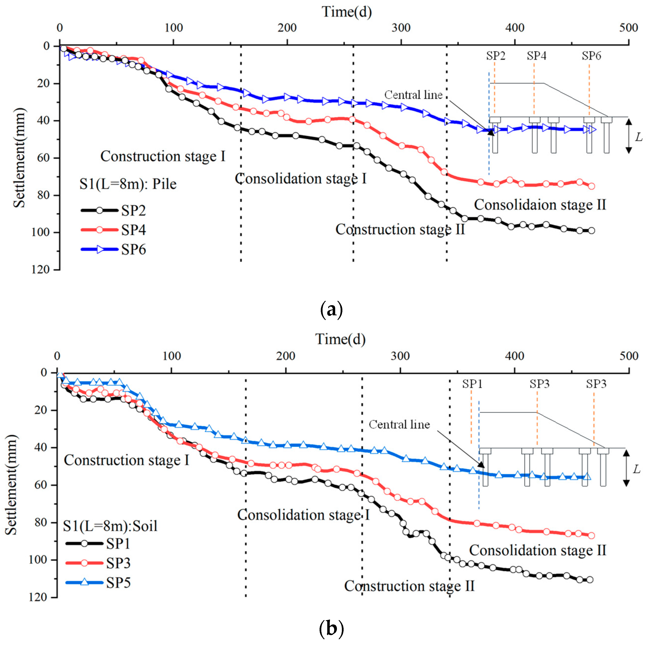
2.3.2. Settlement
2.3.3. The Development of Soil Arching
3. Factors Influencing Soil Arching
3.1. Piles
3.1.1. Pile Shape
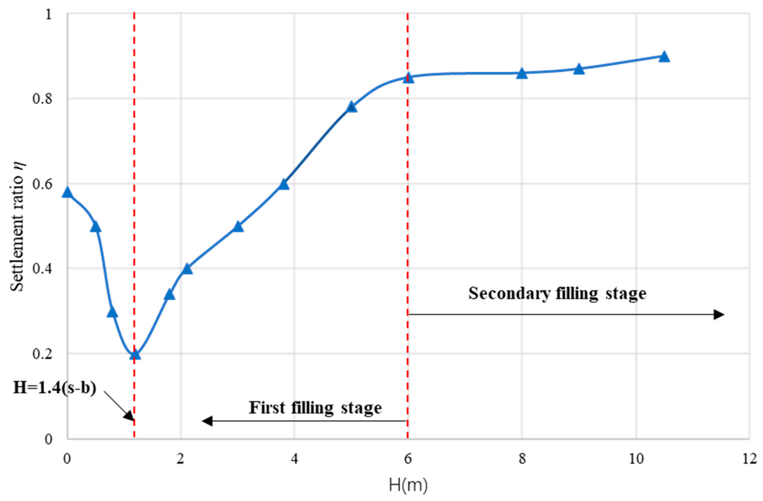
- H/(s − a) directly influences the soil-arching effect in a pile-supported embankment. A higher H/(s − a) generally leads to a higher maximum E, which represents a higher soil-arching effect. A lower H/(s − a) will result in a higher settlement due to the lower degree of soil arching.
- Different values of the coefficient H/(s − a) for pile-supported embankments result in different types of soil arching shapes (discussed in Section 2.3.3). Thus, the minimum height of the embankment fill, under which a full soil arching can be formed, should be considered in the design, in order to give full play to the soil-arching effect to enhance the load transfer.
- With the increase in the spacing between adjoint piles, the soil-arching effect decreases. However, for a given final embankment height, within the scope of the pile spacing, the net cap spacing can be increased without significantly affecting the pile efficiency.
- The soil-arching effect increases with the increase in the pile cap size (this is also observed with the decrease in the clearance spacing between the pile caps).
- For a given pile spacing and embankment height, the longer the pile length, the higher the maximum pile efficiency and replacement ratio and the higher the efficiency, indicating a greater soil-arching effect.
- The shape of the pile body has the most significant influence on the soil-arching effect in the case of the floating-pile embankment. For instance, the load sharing ratios from the sections improved by tube piles are significantly lower than those from the sections improved by Y-shaped piles.
3.1.2. Pile Arrangement
- In a triangular arrangement of the pile-supported embankment, there are two types of soil arching: primary soil arching (between the upper and lower boundaries) and secondary soil arching (below the lower boundary). The primary soil arching mainly plays the role of transferring the load onto the pile caps, and the secondary soil arching transfers the load toward the area between the pile caps. The height to the crown of the arch above the triangular arrangement is lower than that in the case of the square arrangement.
- Compared with the square arrangement of a pile-supported embankment, the triangular arrangement of the piles has a greater soil-arching effect, owing to which a higher embankment load is transferred to the piles, resulting in a lower settlement at the top of the subsoil.
3.1.3. Pile Types
- Regardless of the type of embankment (end-bearing pile embankment or floating pile embankment), the variation in the load distribution with time or embankment height is similar, though there are some differences. The details of the load distribution have been discussed in Section 2.3.1.
- Compared with the end-bearing pile embankment, the floating pile embankment after construction exhibits a greater settlement, as shown in Section 2.3.2. The consolidation settlement accounts for 50–60% of the total settlement in the floating pile embankment, whereas it is small enough to be ignored in the case of the end-bearing pile embankment.
- End-bearing piles carry more load than floating piles, owing to the soil arching and tensioned membrane effects, leading to a greater settlement in the floating pile embankment.
3.2. Embankment Filling
3.3. Subsoil
- Soil strength parameters (cohesion, friction angle, and Young’s modulus) can improve the arching effects but cannot change the shape or prohibit the development of the arching zone for soils whose displacements are sufficient for initial plastic flow.
- A higher modulus ratio between the pile and subsoil will increase the difference in the differential settlement between the pile and subsoil, thus improving the soil arching and increasing the stress ratio. However, if the modulus ratio is greater than 50, the increase rate will be low.
- With the increase in the compression index (Cc), the development of subsoil settlement is accelerated, which accelerates the evolution of the soil arching and increases the stress borne by the geogrid.
- A higher OCR can significantly suppress the growth of subsoil settlement, which decreases the contribution of the geogrid in carrying the embankment load.
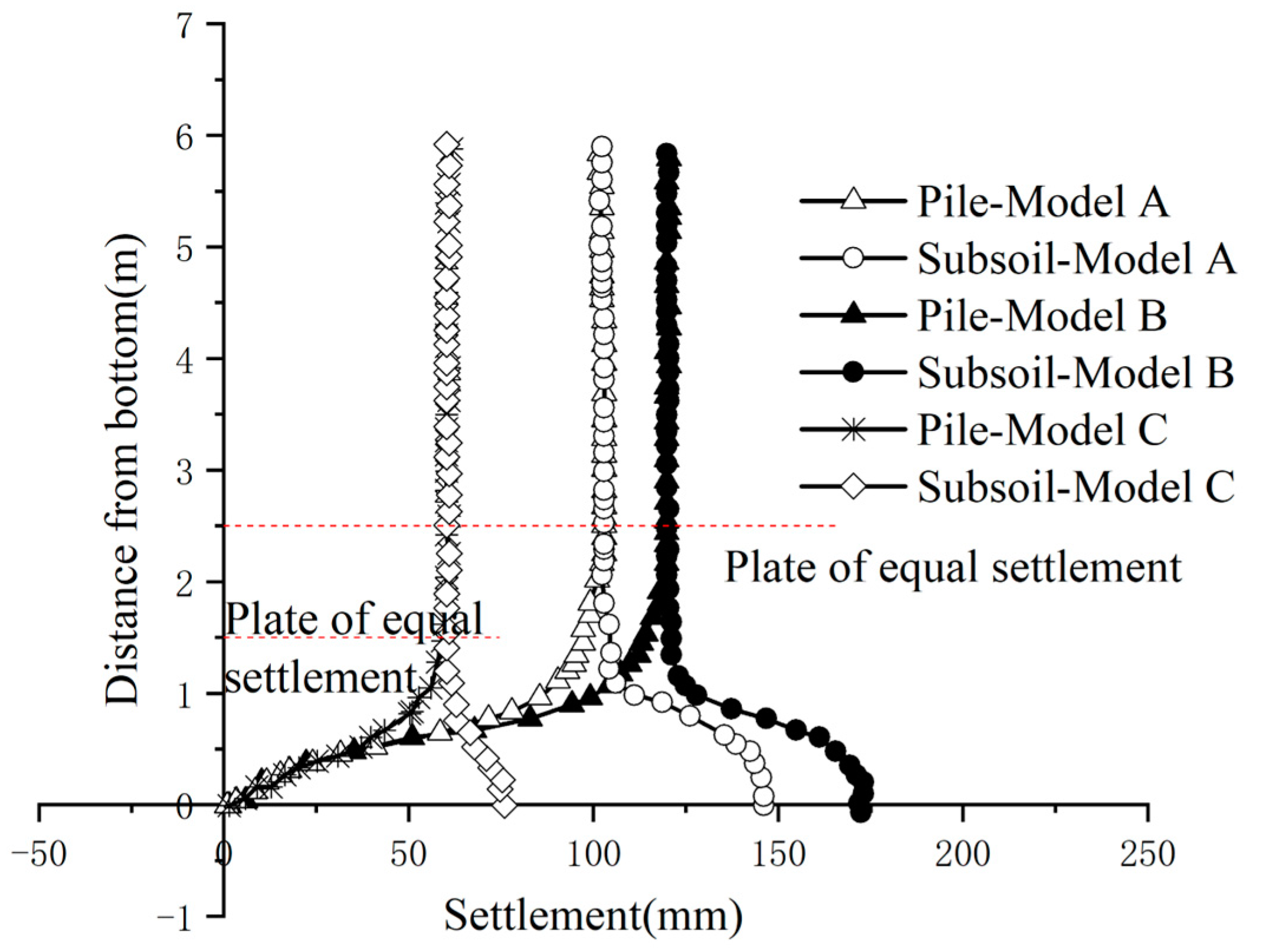
- For the GRPS embankment, the compressibility of the underlying soil does not influence the load transfer mechanism. However, there is a complementary action between the underlying soil and the geosynthetic sheet. A higher compressibility of the underlying soil can limit the movement of the embankment soil, which decreases the displacement of the geosynthetic sheet.
3.4. Geosynthetic Reinforcement
3.4.1. The Properties of Geosynthetic Reinforcement
3.4.2. The Number of Geogrid Layers
3.4.3. Strain in the Geogrid
4. Concluding Remarks
4.1. Load Distribution in Soil
4.2. Deformation in Soil
4.3. Factors Influencing Soil Arching
- Piles with a larger width, smaller spacing, and higher length can improve the soil arching on the embankment, which enhances the load transfer from the subsoil to piles and decreases the settlement.
- Compared with the square arrangement of the pile-supported embankment, the triangular arrangement of piles brings about a greater soil-arching effect, which increases the embankment load transferred to the piles, resulting in a smaller settlement at the top of the subsoil.
- The settlement on a floating pile embankment after construction is greater than that on an end-bearing pile embankment. The consolidation settlement accounts for 50–60% of the total settlement in the floating pile embankments, whereas it is small enough to be ignored on end-bearing pile embankments.
- The shape of the pile body and the pile length have a greater influence on the floating pile embankment. This is mainly because the bearing capacity of a floating pile depends on the side friction resistance, whereas that of the end-bearing pile depends on the pile diameter and strength of the layer-bearing soil.
- An embankment fill with a higher cohesion and friction angle can improve the soil-arching effect, which enhances the load transfer between the subsoil and piles. However, the aforementioned rule is only applicable in a specific range of the cohesion and friction angle.
- The soil strength parameters (cohesion, friction angle, and Young’s modulus) can improve the soil-arching effect but cannot change the shape or prohibit the development of the arching zone in soil whose displacements are sufficient for initial plastic flow.
- A higher compression index will accelerate the development of subsoil settlement and accelerate the evolution of the soil arch.
- There is a complementary action between the underlying soil and the geosynthetic sheet. The higher compressibility of the underlying soil limits the movement of the embankment soil, which decreases the displacement of the geosynthetic sheet.
- The geogrid in the embankment can provide support and limit the lateral spreading of the embankment, and a higher embankment load is transferred to the pile cap. With increasing stiffness, a geogrid will exhibit a higher tension, which applies to embankments under static and dynamic conditions.
- Orthotropic and isotropic membrane models produced results with some differences, indicating that different materials of the geogrid should be considered for GRPS embankments.
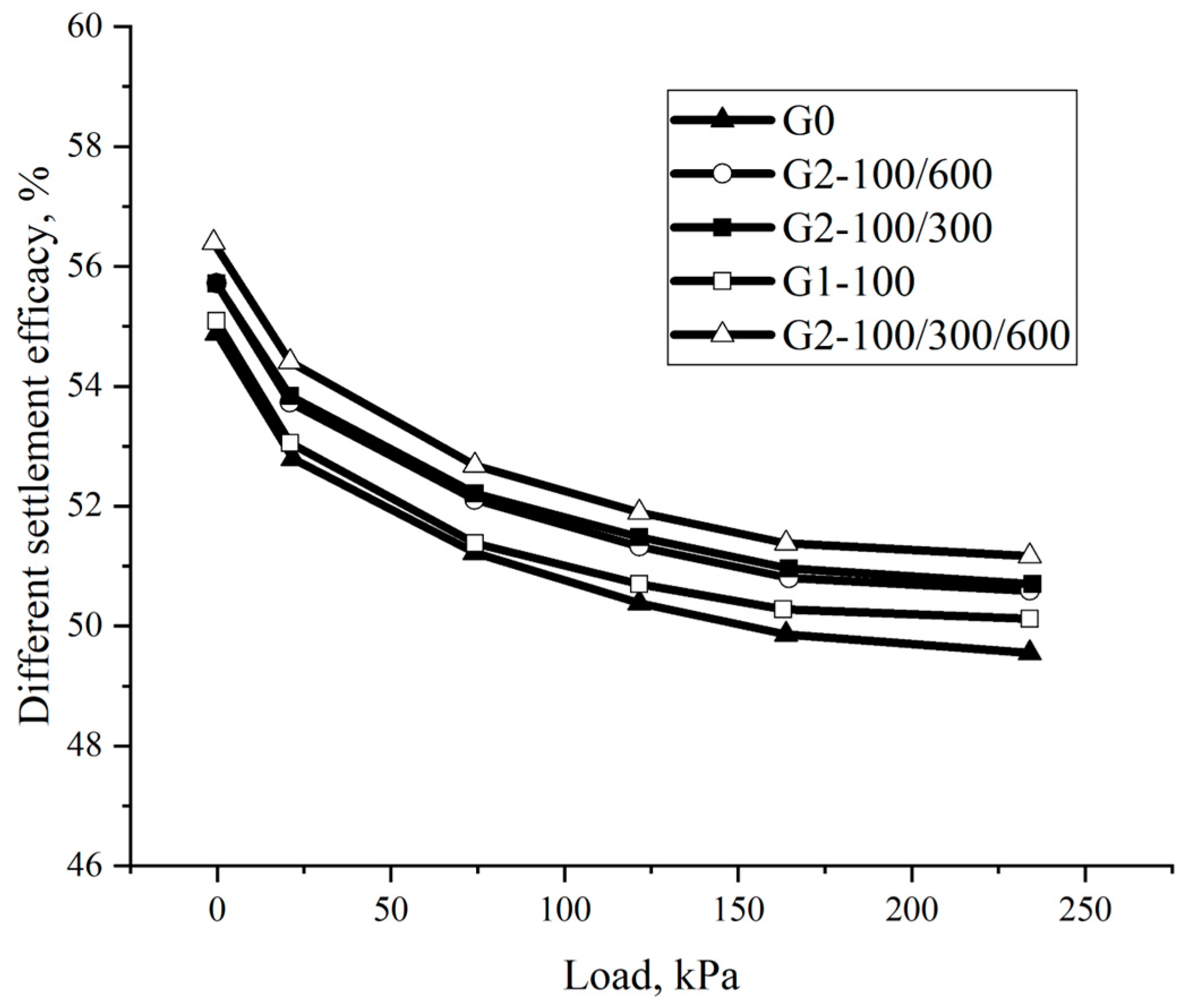
- There were differences in the load distribution and soil settlement for embankments with or without the geogrid. However, the influence of the number of geogrid layers for embankment settlement was small. The number of geogrid layers and the spacing between geogrids had the most significant influence on the differential settlement.
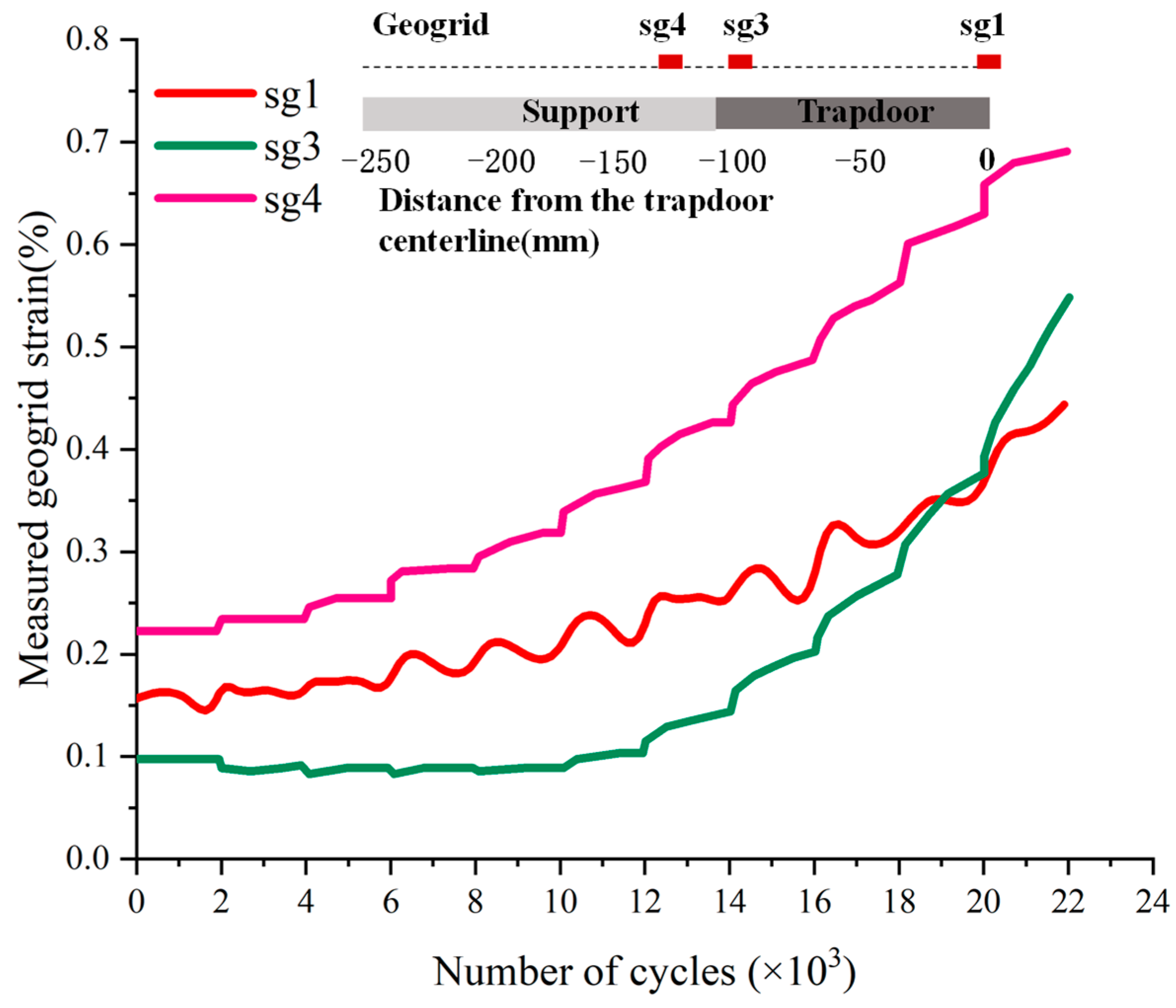
- For the GRPS embankment, the maximum tensile deformation occurred at the edge of the pile cap. During long-term serviceability, the geogrid will strain continually, indicating that the creep of the geogrid should be considered.
5. Future Prospects
- A comparison between end-bearing and floating pile embankments during construction, consolidation, and long-term operation can be made in terms of the load distribution.
- A comparison between end-bearing and floating pile embankments during consolidation can be made in terms of the total and differential settlements.
- The impact of changes in the water level in the embankment fill on soil arching can be studied.
- The impact of changes in the water level in the subsoil on the side friction of floating piles can be studied.
- The load distribution and soil deformation of the embankment under the combined effect of traffic load and water should be investigated.
- The distribution of the side-friction resistance of floating piles with the pile length, particularly the friction resistance at the interface between different types of soil layers, can be analyzed.
- Variations in the tension and strain of the geogrid during long-term operation can be explored.
- A suitable stiffness range for the geogrid should be determined; if the stiffness of the reinforced body is too low, it will have little effect on the soil-arching phenomenon; if the reinforcement has a large stiffness, it will have a lower ductility, and excessive deformation can lead to failure.
Author Contributions
Funding
Data Availability Statement
Acknowledgments
Conflicts of Interest
Notations
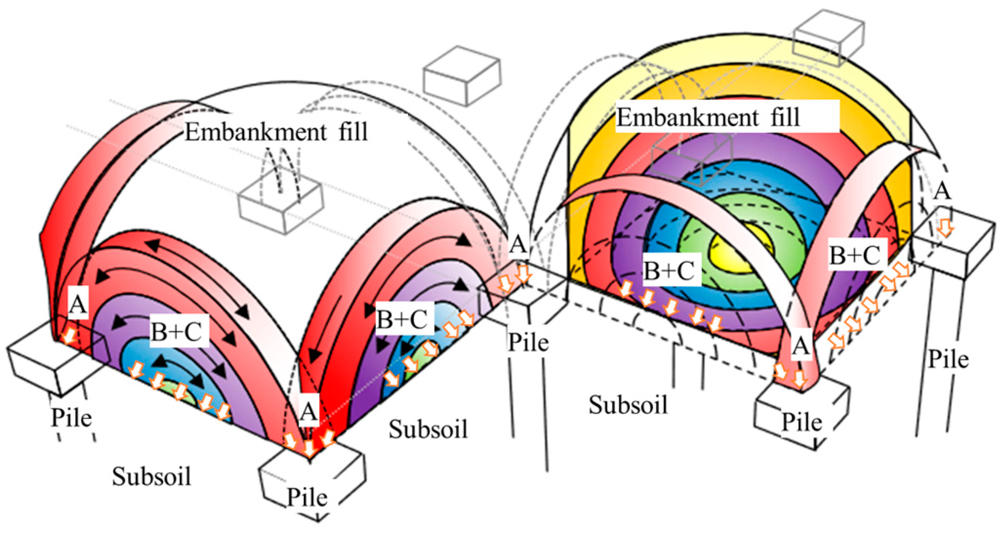
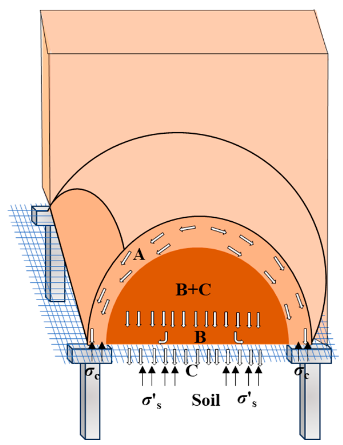
| A | total load is transferred to the pile through soil arching |
| B | load transferred to the piles through the reinforcement |
| C | load is borne by the subsoil |
| E | proportion of embankment weight carried by the piles |
| Ea | efficacy components corresponding to the arching effects |
| Em | efficacy components corresponding to membrane effects |
| SRR | stress reduction ratio |
| SSRa | SRR induced by the arching effect |
| SSRm | SRR induced by the membrane effect |
| FGRsquare | total vertical load exerted by the 3D hemispheres on the square subsurface |
| FGRstrips | total load on the GR strips |
| Wtotal | weight of the embankment fill |
| H | embankment fill height |
| Kp | Rankine’s passive earth pressure coefficient |
| KG | tensile stiffness of the geotextile |
| L | width of the sliding plates |
| D | depth of the soft ground |
| p | uniformly distributed surcharge on top of the fill (top load) |
| b | width of the pile cap |
| c | cohesion of the soil |
| δ | ratio of the width of the pile cap to the centerline space between adjacent piles |
| q | uniform surcharge acting on the embankment fill |
| θ | deflected angle of geosynthetic |
| s | centerline space between adjacent piles |
| s′ | clear spacing between adjacent piles |
| sx | spacings in the x-directions |
| sy | spacings in the y-directions |
| γ | unit weight of the soil |
| γs | unit weight of the embankment fill |
| T | total GR tensile force |
| t | soft-ground deflection midway between the cap beams reinforced with the geotextile |
| pc | vertical stress acting on the pile cap |
| σs | pressure acting on the subsoil |
| σs′ | equivalent uniform stress on the subsoil |
| σk | horizontal stress acting on the soil |
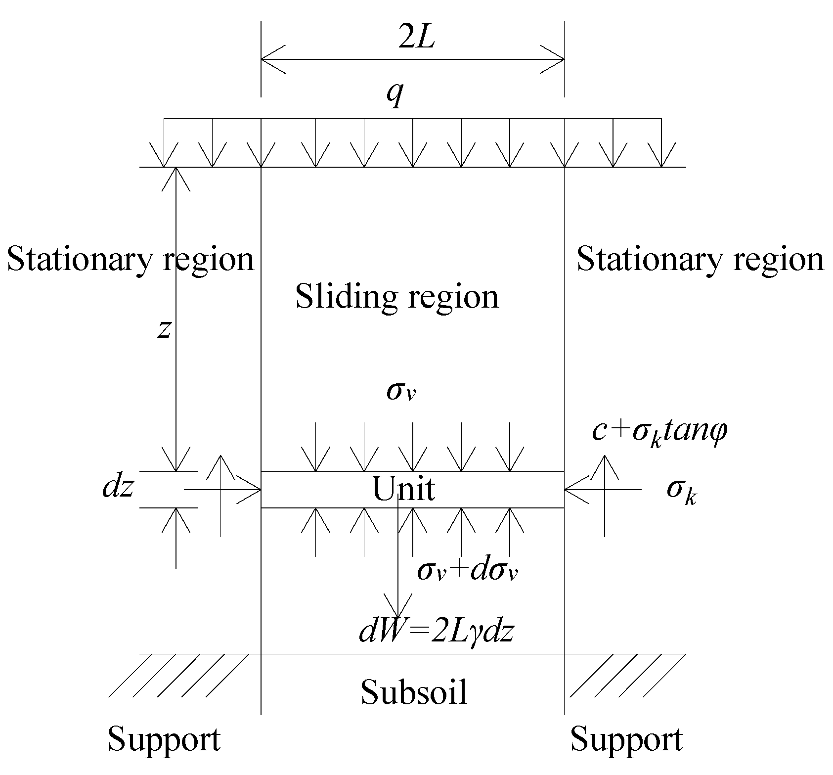
| σv | vertical stress at any depth into the soil |
| dz | thickness of a unit |
| z | depth of unit in Figure 4 |
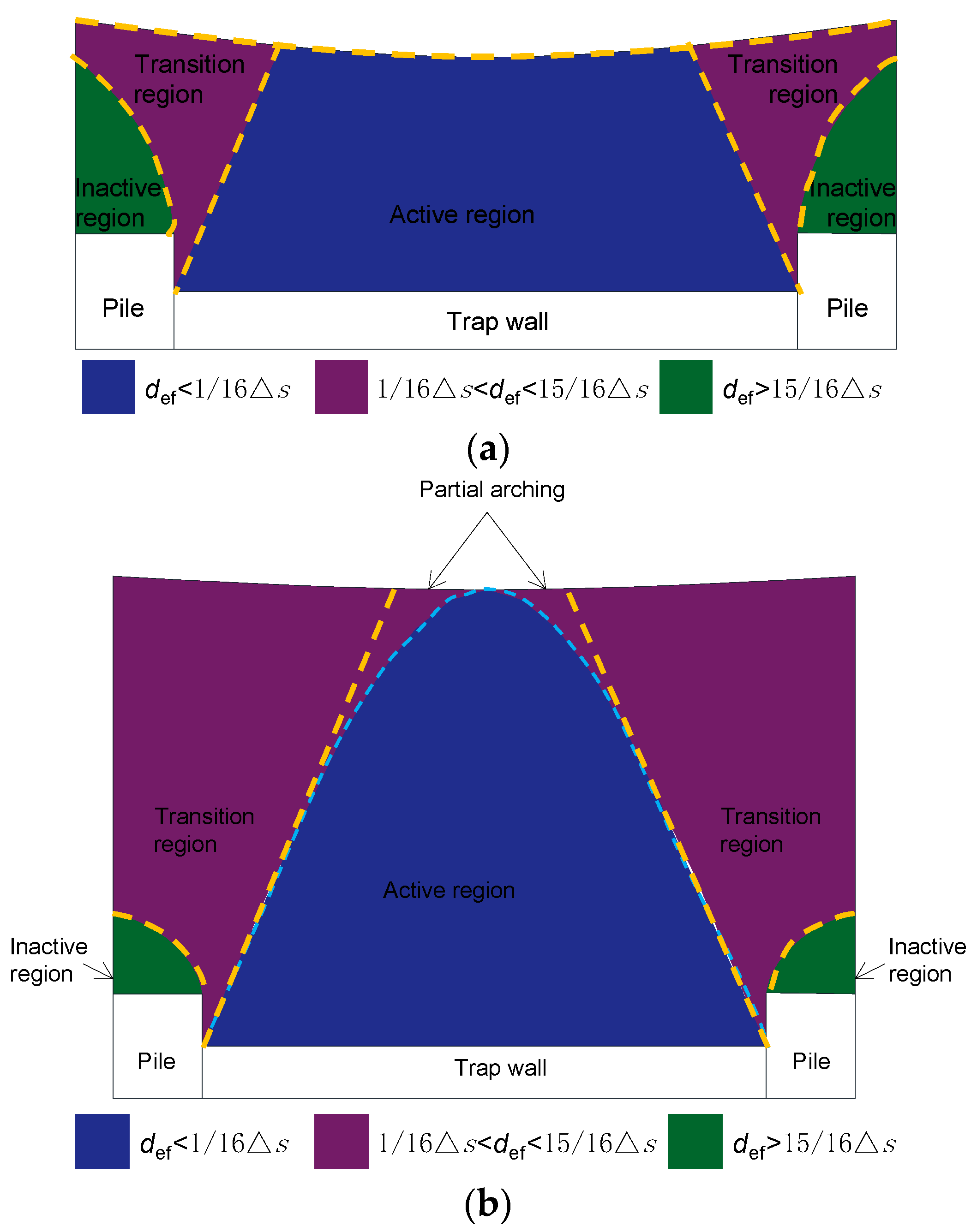
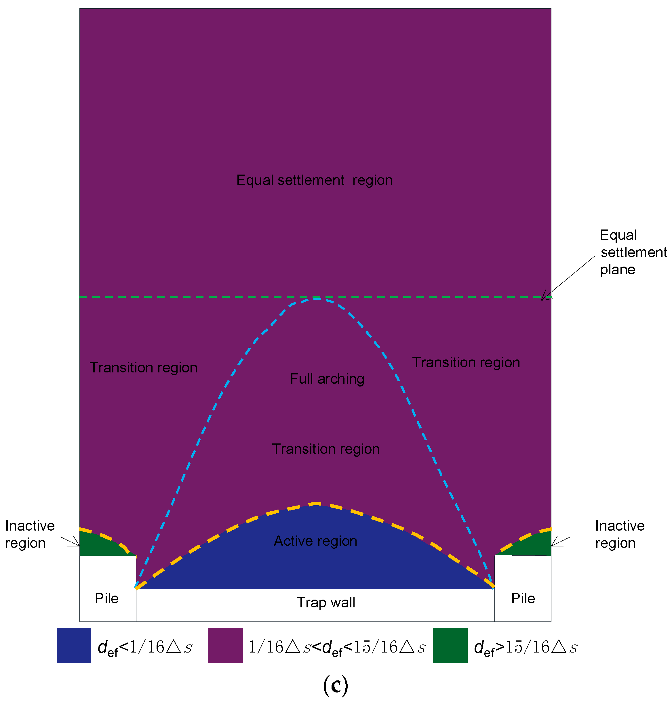
| def | displacements of embankment fill in Figure 15 |
| Δs | pile–subsoil relative displacement. However, this is compared with the shear plane in Figure 15. |
References
- Liu, H.L.; Li, H.; Peng, J.; Gao, Y.F. Indoor Experimental Study on Vacuum Heap Load Combined Preloading for Strengthening Soft Foundation. J. Geotech. Eng. 2004, 26, 145–149. [Google Scholar]
- Xue, R.; Hu, R.L.; Mao, L.T. Fractal Study on Microstructure Changes during Soft Soil Reinforcement Process. China Civ. Eng. J. 2006, 39, 87–91. [Google Scholar] [CrossRef]
- Zheng, Y.R.; Li, X.Z.; Feng, Y.X.; Zhou, L.Z.; Lu, X.; He, H.Y. Research on the Mechanism and Technology of Dynamic Compaction of Soft Clay Foundation. J. Rock Mech. Eng. 1998, 17, 571–580. [Google Scholar]
- Liu, H.L.; Fei, K.; Ma, X.H.; Gao, Y.F. Vibration Sinking Mold Large Diameter Cast-in-Place Thin-Walled Pipe Piles Application (I): Development and Design. Rock Soil Mech. 2003, 24, 164–168. [Google Scholar] [CrossRef]
- Bhasi, A.; Rajagopal, K. Numerical Study of Basal Reinforced Embankments Supported on Floating/End Bearing Piles Considering Pile–Soil Interaction. Geotext. Geomembr. 2015, 43, 524–536. [Google Scholar] [CrossRef]
- Girout, R.; Blanc, M.; Thorel, L.; Dias, D. Geosynthetic Reinforcement of Pile-Supported Embankments. Geosynth. Int. 2018, 25, 37–49. [Google Scholar] [CrossRef]
- Van Eekelen, S.J.M.; Han, J. Geosynthetic-Reinforced Pile-Supported Embankments: State of the Art. Geosynth. Int. 2020, 27, 112–141. [Google Scholar] [CrossRef]
- Lewis, W.A. The Settlement of the Approach Embankments to a New Road Bridge at Lackford, West Suffolk. Geotechnique 1956, 6, 106–114. [Google Scholar] [CrossRef]
- Rowe, R.K.; MacLean, M.D.; Barsvary, A.K. The Observed Behaviour of a Geotextile-Reinforced Embankment Constructed on Peat. Can. Geotech. J. 1984, 21, 289–304. [Google Scholar] [CrossRef]
- Rowe, R.K.; Maclean, M.D.; Soderman, K.L. Analysis of a Geotextile-Reinforced Embankment Constructed on Peat. Can. Geotech. J. 1984, 3, 563–576. [Google Scholar] [CrossRef]
- Terzaghi, K. Stress Distribution in Dry and in Saturated Sand above a Yielding Trap-Door. In Proceedings of the International Conference of Soil Mechanics, Harvard University, Cambridge, MA, USA, 22–26 June 1936; pp. 307–311. [Google Scholar]
- Terzaghi, K. Theoretical Soil Mechanics; John Wiley and Sons: New York, NY, USA, 1943; pp. 307–311. [Google Scholar]
- Hewlett, W.J.; Randolph, M.F. Analysis of Piled Embankments. Ground Eng. 1988, 21, 12–18. [Google Scholar]
- Reid, W.M.; Buchanan, N.W. BRIDGE APPROACH SUPPORT PILING. In Proceedings of the International Conference on Advances in Piling and Ground Treatment, London, UK, 2–4 March 1983; ICE Publishing: London, UK, 1983; pp. 267–274. [Google Scholar]
- Kempfert, H.G.; Stadel, M.; Zaeske, D. Berechnung von Geokunstst off bewerten Trags Chichten Über Pfahlelementen. Bautechnik 1997, 74, 818–825. [Google Scholar]
- Kempfert, H.G.; Zaeske, D. Interactions in Reinforced Bearing Layers over Partial Supported Underground. In Proceedings of the Twelfth European Conference on Soil Mechanics and Geotechnical Engineering (Proceedings), Amsterdam, The Netherlands, 7–10 June 1999. [Google Scholar]
- Carlson, B.O. Armerad Jord Beräkningsprinciper För Banker På Pålar; Terranova, Distr. SGI: Linköping, Sweden, 1987. [Google Scholar]
- Guido, V.A.; Knueppel, J.D.; Sweeny, M.A. Plate Loading Tests on Geogrid-Reinforced Earth Slabs. Proc. Geosynth. 1987, 87, 216–225. [Google Scholar]
- Jones, C.J.F.P.; Lawson, C.R.; Ayres, D.J. Geotextile Reinforced Piled Embankments; Balkema: Rotterdam, The Netherlands, 1990; pp. 155–160. [Google Scholar]
- Kempton, G.T.; Jones, C.J.F.P. The Use of High Strength Link Geotextiles over Piles and Voids; Balkema: Rotterdam, The Netherlands, 1992; pp. 613–618. [Google Scholar]
- Low, B.K.; Tang, S.K. Arching in Piled Embankments. J. Geotech. Eng. 1994, 120, 1917–1938. [Google Scholar] [CrossRef]
- BSI (1995) BS8006; Code of Practice for Strengthened/Reinforced Soils and Other Fills. British Standards Institution: London, UK, 1995.
- BSI (2010) BS8006-1; Code of Practice for Strengthened/Reinforced Soils and Other Fills. British Standards Institution: London, UK, 2010.
- EBGEO. Empfehlungen Für Den Entwurf Und Die Berechnung von Erdkörpern Mit Bewehrungen Aus Geokunststoffen—EBGEO; Ernst & Sohn: Berlin, Germany, 2010. [Google Scholar]
- Van Eekelen, S.J.M.; Brugman, M.H.A. Design Guideline Basal Reinforced Piled Embankments; CUR226; SBRCURnet: Delft, The Netherland, 2016. [Google Scholar]
- Schaefer, V.R.; Berg, R.R.; Collin, J.G.; Christopher, B.R.; DiMaggio, J.A.; Filz, G.M.; Bruce, D.A.; Ayala, D. Ground Improvement Methods—Reference Manual Vols. I and II; FHWA-NHI-16-027 and FHWA-NHI-16-028 2017; Federal Highway Administration, U.S. Department of Transportation: Washington, DC, USA, 2017.
- Handy, R.L. The Arch in Soil Arching. J. Geotech. Eng. 1985, 111, 302–318. [Google Scholar] [CrossRef]
- Kellogg, C.G. Discussion of “The Arch in Soil Arching” by Richard L. Handy (March, 1985, Vol. 111, No. 3). J. Geotech. Eng. 1987, 113, 302–318. [Google Scholar] [CrossRef]
- Railway Technology Research Institute. The Design and Construction Handbook of Mixing Piled Foundation (Machine Mixing); Railway Technology Research Institute: Tokyo, Japan, 2001. [Google Scholar]
- Nordic Geosynthetic Group. Nordic Guidelines for Reinforced Soils and Fills; Nordic Geotechnical Group: Stockholm, Sweden, 2004. [Google Scholar]
- Kempfert, H.G.; Göbel, C.; Alexiew, D.; Heitz, C. German Recommendations for Reinforced Embankments on Pile-Similar Elements. In Proceedings of the EuroGeo3, Munich, Germany, 1–4 March 2004; pp. 279–284. [Google Scholar]
- Van Eekelen, S.J.M.; Bezuijen, A.; Van Tol, A.F. An Analytical Model for Arching in Piled Embankments. Geotext. Geomembr. 2013, 39, 78–102. [Google Scholar] [CrossRef]
- Van Eekelen, S.J.M.; Bezuijen, A.; Van Tol, A.F. Validation of Analytical Models for the Design of Basal Reinforced Piled Embankments. Geotext. Geomembr. 2015, 43, 56–81. [Google Scholar] [CrossRef]
- Rui, R.; Van Tol, F.; Xia, X.-L.; Van Eekelen, S.; Hu, G.; Xia, Y. Evolution of Soil Arching; 2D DEM Simulations. Comput. Geotech. 2016, 73, 199–209. [Google Scholar] [CrossRef]
- Zhang, Z.; Tao, F.; Han, J.; Ye, G.; Cheng, B.; Liu, L. Influence of Surface Footing Loading on Soil Arching above Multiple Buried Structures in Transparent Sand. Can. J. Civ. Eng. 2021, 48, 124–133. [Google Scholar] [CrossRef]
- Zhang, Z.; Tao, F.-J.; Han, J.; Ye, G.-B.; Cheng, B.-N.; Xu, C. Arching Development in Transparent Soil during Multiple Trapdoor Movement and Surface Footing Loading. Int. J. Geomech. 2021, 21, 04020262. [Google Scholar] [CrossRef]
- Hong, W.P.; Lee, J.H.; Lee, K.W. Load Transfer by Soil Arching in Pile-Supported Embankments. Soils Found. 2007, 47, 833–843. [Google Scholar] [CrossRef]
- Wang, T.; Nguyen, V.D.; Bui, P.D.; Luo, Q.; Liu, K.; Zhang, L. Three-Dimensional Physical Modeling of Load Transfer in Basal Reinforced Embankments under Differential Settlement. Geotext. Geomembr. 2023, 51, 330–341. [Google Scholar] [CrossRef]
- Chevalier, B.; Combe, G.; Villard, P. Experimental and Discrete Element Modeling Studies of the Trapdoor Problem: Influence of the Macro-Mechanical Frictional Parameters. Acta Geotech. 2012, 7, 15–39. [Google Scholar] [CrossRef]
- Jenck, O.; Combe, G.; Emeriault, F.; De Pasquale, A. Arching Effect in a Granular Soil Subjected to Monotonic or Cyclic Loading: Kinematic Analysis. In Proceedings of the ICPMG2014—Physical Modelling in Geotechnics, Perth, Australia, 14–17 January 2014; Gaudin, C., White, D., Eds.; CRC Press: Boca Raton, FL, USA, 2014; pp. 1243–1249, ISBN 978-1-138-00152-7. [Google Scholar]
- Xu, C.; Zhang, X.; Han, J.; Yang, Y. Two-Dimensional Soil-Arching Behavior under Static and Cyclic Loading. Int. J. Geomech. 2019, 19, 04019091. [Google Scholar] [CrossRef]
- Al-Naddaf, M.; Han, J.; Xu, C.; Jawad, S.; Abdulrasool, G. Experimental Investigation of Soil Arching Mobilization and Degradation under Localized Surface Loading. J. Geotech. Geoenviron. Eng. 2019, 145, 04019114. [Google Scholar] [CrossRef]
- Al-Naddaf, M.; Han, J. Spring-Based Trapdoor Tests Investigating Soil Arching Stability in Embankment Fill under Localized Surface Loading. J. Geotech. Geoenviron. Eng. 2021, 147, 04021087. [Google Scholar] [CrossRef]
- Naughton, P.J.; Kempton, G.T. Comparison of Analytical and Numerical Analysis Design Methods for Piled Embankments. In Proceedings of the Contemporary Issues in Foundation Engineering, Austin, TX, USA, 24–26 January 2005; American Society of Civil Engineers: Reston, VA, USA, 2005; pp. 1–10. [Google Scholar]
- Van Eekelen, S.J.M.; Van, M.A.; Bezuijen, A. The Kyoto Road, a Full-Scale Test. Measurements and Calculations. In Proceedings of the 14th European Conference on Soil Mechanics and Geotechnical Engineering, Madrid, Spain, 24–27 September 2007; pp. 1533–1538. [Google Scholar]
- Abusharar, S.W.; Zheng, J.-J.; Chen, B.-G.; Yin, J.-H. A Simplified Method for Analysis of a Piled Embankment Reinforced with Geosynthetics. Geotext. Geomembr. 2009, 27, 39–52. [Google Scholar] [CrossRef]
- Al-Ani, W.; Wanatowski, D.; Chan, S.H. Numerical Analysis of Piled Embankments on Soft Soils. In Proceedings of the Ground Improvement and Geosynthetics, Shanghai, China, 26–28 May 2014; American Society of Civil Engineers: Reston, VA, USA, 2014; pp. 30–39. [Google Scholar]
- Zhuang, Y.; Wang, K.Y. Finite-Element Analysis on the Effect of Subsoil in Reinforced Piled Embankments and Comparison with Theoretical Method Predictions. Int. J. Geomech. 2016, 16, 04016011. [Google Scholar] [CrossRef]
- Wang, H.-L.; Chen, R.-P. Estimating Static and Dynamic Stresses in Geosynthetic-Reinforced Pile-Supported Track-Bed under Train Moving Loads. J. Geotech. Geoenviron. Eng. 2019, 145, 04019029. [Google Scholar] [CrossRef]
- Van Eekelen, S.J.M.; Bezuijen, A.; Van Tol, A.F. Analysis and Modification of the British Standard BS8006 for the Design of Piled Embankments. Geotext. Geomembr. 2011, 29, 345–359. [Google Scholar] [CrossRef]
- Zhuang, Y.; Wang, K.Y.; Liu, H.L. A Simplified Model to Analyze the Reinforced Piled Embankments. Geotext. Geomembr. 2014, 42, 154–165. [Google Scholar] [CrossRef]
- Pham, T.A. Analysis of Geosynthetic-Reinforced Pile-Supported Embankment with Soil-Structure Interaction Models. Comput. Geotech. 2020, 121, 103438. [Google Scholar] [CrossRef]
- Pham, T.A. Load-Deformation of Piled Embankments Considering Geosynthetic Membrane Effect and Interface Friction. Geosynth. Int. 2020, 27, 275–300. [Google Scholar] [CrossRef]
- Pham, T.A.; Wijesuriya, K.; Dias, D. Analytical Model for the Design of Piled Embankments Considering Cohesive Soils. Geosynth. Int. 2022, 29, 369–388. [Google Scholar] [CrossRef]
- Chen, Y.-M.; Cao, W.-P.; Chen, R.-P. An Experimental Investigation of Soil Arching within Basal Reinforced and Unreinforced Piled Embankments. Geotext. Geomembr. 2008, 26, 164–174. [Google Scholar] [CrossRef]
- Han, J.; Gabr, M.A. Numerical Analysis of Geosynthetic-Reinforced and Pile-Supported Earth Platforms over Soft Soil. J. Geotech. Geoenviron. Eng. 2002, 128, 44–53. [Google Scholar] [CrossRef]
- Murugesan, S.; Rajagopal, K. Geosynthetic-Encased Stone Columns: Numerical Evaluation. Geotext. Geomembr. 2006, 24, 349–358. [Google Scholar] [CrossRef]
- Nguyen, V.D.; Luo, Q.; Xue, Y.; Wang, T.; Zhang, L.; Zhang, D. Extended Concentric Arches Model for Piled Beam-Supported Embankments. Comput. Geotech. 2023, 160, 105517. [Google Scholar] [CrossRef]
- Wang, T.; Ma, H.; Liu, K.; Luo, Q.; Xiao, S. Load Transfer and Performance Evaluation of Piled Beam-Supported Embankments. Acta Geotech. 2022, 17, 4145–4171. [Google Scholar] [CrossRef]
- Wang, G.; Zhang, X.; Liu, X.; Wang, H.; Xu, L.; Liu, H.; Peng, L. Soil Arching Effect in Reinforced Piled Embankment for Motor-Racing Circuit: Field Tests and Numerical Analysis. Transp. Geotech. 2022, 37, 100844. [Google Scholar] [CrossRef]
- Rowe, R.K.; Liu, K.-W. Three-Dimensional Finite Element Modelling of a Full-Scale Geosynthetic-Reinforced, Pile-Supported Embankment. Can. Geotech. J. 2015, 52, 2041–2054. [Google Scholar] [CrossRef]
- Van Eekelen, S.J.M.; Bezuijen, A.; Lodder, H.J.; Van Tol, A.F. Model Experiments on Piled Embankments. Part I. Geotext. Geomembr. 2012, 32, 69–81. [Google Scholar] [CrossRef]
- Van Eekelen, S.J.M.; Bezuijen, A.; Lodder, H.J.; Van Tol, A.F. Model Experiments on Piled Embankments. Part II. Geotext. Geomembr. 2012, 32, 82–94. [Google Scholar] [CrossRef]
- Ye, X.; Wu, J.; Li, G. Time-Dependent Field Performance of PHC Pile-Cap-Beam-Supported Embankment over Soft Marine Clay. Transp. Geotech. 2021, 26, 100435. [Google Scholar] [CrossRef]
- Zhuang, Y.; Wang, K. Finite Element Analysis on the Dynamic Behavior of Soil Arching Effect in Piled Embankment. Transp. Geotech. 2018, 14, 8–21. [Google Scholar] [CrossRef]
- Zheng, G.; Yang, X.; Zhou, H.; Chai, J. Numerical Modeling of Progressive Failure of Rigid Piles under Embankment Load. Can. Geotech. J. 2019, 56, 23–34. [Google Scholar] [CrossRef]
- Ma, H.; Luo, Q.; Wang, T.; Jiang, H.; Lu, Q. Numerical Stability Analysis of Piled Embankments Reinforced with Ground Beams. Transp. Geotech. 2021, 26, 100427. [Google Scholar] [CrossRef]
- Hosseinpour, I.; Riccio, M.; Almeida, M.S.S. Numerical Evaluation of a Granular Column Reinforced by Geosynthetics Using Encasement and Laminated Disks. Geotext. Geomembr. 2014, 42, 363–373. [Google Scholar] [CrossRef]
- Hosseinpour, I.; Almeida, M.S.S.; Riccio, M. Full-Scale Load Test and Finite-Element Analysis of Soft Ground Improved by Geotextile-Encased Granular Columns. Geosynth. Int. 2015, 22, 428–438. [Google Scholar] [CrossRef]
- Zhang, C.; Su, L.; Jiang, G. Full-Scale Model Tests of Load Transfer in Geogrid-Reinforced and Floating Pile-Supported Embankments. Geotext. Geomembr. 2022, 50, 896–909. [Google Scholar] [CrossRef]
- Pan, G.; Liu, X.; Yuan, S.; Wang, Y.; Sun, D.; Feng, Y.; Jiang, G. A Field Study on the Arching Behavior of a Geogrid-Reinforced Floating Pile-Supported Embankment. Transp. Geotech. 2022, 37, 100795. [Google Scholar] [CrossRef]
- Zhuang, Y.; Wang, K.Y. Finite-Element Analysis of Arching in Highway Piled Embankments Subjected to Moving Vehicle Loads. Géotechnique 2018, 68, 857–868. [Google Scholar] [CrossRef]
- Qin, C.; Hazarika, H.; Pasha, S.M.K.; Furuichi, H.; Kochi, Y.; Matsumoto, D.; Fujishiro, T.; Ishibashi, S.; Watanabe, N.; Yamamoto, S. Evaluation of Hybrid Pile Supported System for Protecting Road Embankment Under Seismic Loading. In Advances in Sustainable Construction and Resource Management; Hazarika, H., Madabhushi, G.S.P., Yasuhara, K., Bergado, D.T., Eds.; Lecture Notes in Civil Engineering; Springer: Singapore, 2021; Volume 144, pp. 733–744. ISBN 9789811600760. [Google Scholar]
- Chen, Y.; Ma, S.; Ren, Y.; Chen, R.; Bian, X. Experimental Study on Cyclic Settlement of Piles in Silt Soil and Its Application in High-Speed Railway Design. Transp. Geotech. 2021, 27, 100496. [Google Scholar] [CrossRef]
- Qin, C.; Hazarika, H.; Rohit, D.; Ogawa, N.; Kochi, Y.; Liu, G. Numerical Simulation of Seismic Performance of Road Embankment Improved with Hybrid Type Steel Pile Reinforcement; Springer: Beijing, China, 2022; pp. 1332–1339. [Google Scholar]
- Lai, H.-J.; Zheng, J.-J.; Zhang, J.; Zhang, R.-J.; Cui, L. DEM Analysis of “Soil”-Arching within Geogrid-Reinforced and Unreinforced Pile-Supported Embankments. Comput. Geotech. 2014, 61, 13–23. [Google Scholar] [CrossRef]
- Lai, H.-J.; Zhang, J.-J.; Zhang, R.-J.; Cui, M.-J. Visualization of the Formation and Features of Soil Arching within a Piled Embankment by Discrete Element Method Simulation. J. Zhejiang Univ.-Sci. Appl. Phys. Eng. 2016, 17, 803–817. [Google Scholar] [CrossRef]
- Lai, H.-J.; Zheng, J.-J.; Zhang, R.-J.; Cui, M.-J. Classification and Characteristics of Soil Arching Structures in Pile-Supported Embankments. Comput. Geotech. 2018, 98, 153–171. [Google Scholar] [CrossRef]
- Lai, H.-J.; Zheng, J.-J.; Cui, M.-J.; Chu, J. “Soil Arching” for Piled Embankments: Insights from Stress Redistribution Behaviour of DEM Modelling. Acta Geotech. 2020, 15, 2117–2136. [Google Scholar] [CrossRef]
- Papamichos, E.; Vardoulakis, I.; Heil, L.K. Overburden Modeling above a Compacting Reservoir Using a Trap Door Apparatus. Phys. Chem. Earth Part Solid Earth Geod. 2001, 26, 69–74. [Google Scholar] [CrossRef]
- Van Eekelen, S.J.M.; Bezuijen, A.; Oung, O. Arching in Piled Embankments; Experiments and Design Calculations. In BGA International Conference on Foundations: Innovations, Observations, Design and Practice, Proceedings of the International Conference Organised by British Geotechnical Association and Held in Dundee, Scotland on 2–5 September 2003; Thomas Telford Publishing: London, UK, 2003; pp. 885–894. [Google Scholar]
- Shahin, H.M.; Nakai, T.; Hinokio, M.; Kurimoto, T.; Sada, T. Influence of Surface Loads and Construction Sequence on Ground Response Due to Tunnelling. Soils Found. 2004, 44, 71–84. [Google Scholar] [CrossRef]
- Rui, R.; Van Tol, A.F.; Xia, Y.Y.; Van Eekelen, S.J.M.; Hu, G. Investigation of Soil-Arching Development in Dense Sand by 2D Model Tests. Geotech. Test. J. 2016, 39, 20150130. [Google Scholar] [CrossRef]
- Rui, R.; Han, J.; Zhang, L.; Zhai, Y.; Cheng, Z.; Chen, C. Simplified Method for Estimating Vertical Stress-Settlement Responses of Piled Embankments on Soft Soils. Comput. Geotech. 2020, 119, 103365. [Google Scholar] [CrossRef]
- Rui, R.; Ye, Y.; Han, J.; Zhai, Y.; Wan, Y.; Chen, C.; Zhang, L. Two-Dimensional Soil Arching Evolution in Geosynthetic-Reinforced Pile-Supported Embankments over Voids. Geotext. Geomembr. 2022, 50, 82–98. [Google Scholar] [CrossRef]
- Xu, C.; Song, S.; Han, J. Scaled Model Tests on Influence Factors of Full Geosynthetic-Reinforced Pile-Supported Embankments. Geosynth. Int. 2016, 23, 140–153. [Google Scholar] [CrossRef]
- Chen, R.P.; Chen, Y.M.; Han, J.; Xu, Z.Z. A Theoretical Solution for Pile-Supported Embankments on Soft Soils under One-Dimensional Compression. Can. Geotech. J. 2008, 45, 611–623. [Google Scholar] [CrossRef]
- Lee, T.; Van Eekelen, S.J.M.; Jung, Y.-H. Numerical Verification of the Concentric Arches Model for Geosynthetic-Reinforced Pile-Supported Embankments: Applicability and Limitations. Can. Geotech. J. 2021, 58, 441–454. [Google Scholar] [CrossRef]
- Samira, F.; Larbi, M.; Mouloud, M.; Laurent, B. Subsoil Compressibility Effect in an End Bearing Scaled Pile-Supported Embankment, Investigation of the Load Transfer Mechanism. Innov. Infrastruct. Solut. 2022, 7, 75. [Google Scholar] [CrossRef]
- Chen, R.P.; Xu, Z.Z.; Chen, Y.M.; Ling, D.S.; Zhu, B. Field Tests on Pile-Supported Embankments over Soft Ground. J. Geotech. Geoenviron. Eng. 2010, 136, 777–785. [Google Scholar] [CrossRef]
- Esmaeili, M.; Khajehei, H. Mechanical Behavior of Embankments Overlying on Loose Subgrade Stabilized by Deep Mixed Columns. J. Rock Mech. Geotech. Eng. 2016, 8, 651–659. [Google Scholar] [CrossRef]
- Rui, R.; Han, J.; Van Eekelen, S.J.M.; Wan, Y. Experimental Investigation of Soil-Arching Development in Unreinforced and Geosynthetic-Reinforced Pile-Supported Embankments. J. Geotech. Geoenviron. Eng. 2019, 145, 04018103. [Google Scholar] [CrossRef]
- Zhang, C.; Jiang, G.; Liu, X.; Buzzi, O. Arching in Geogrid-Reinforced Pile-Supported Embankments over Silty Clay of Medium Compressibility: Field Data and Analytical Solution. Comput. Geotech. 2016, 77, 11–25. [Google Scholar] [CrossRef]
- Lai, H.-J.; Zheng, J.-J.; Cui, M.-J. Improved Analytical Soil Arching Model for the Design of Piled Embankments. Int. J. Geomech. 2021, 21, 04020261. [Google Scholar] [CrossRef]
- Zhang, Z.; Wang, M.; Ye, G.-B.; Han, J. A Novel 2D-3D Conversion Method for Calculating Maximum Strain of Geosynthetic Reinforcement in Pile-Supported Embankments. Geotext. Geomembr. 2019, 47, 336–351. [Google Scholar] [CrossRef]
- Meena, N.K.; Nimbalkar, S.; Fatahi, B.; Yang, G. Effects of Soil Arching on Behavior of Pile-Supported Railway Embankment: 2D FEM Approach. Comput. Geotech. 2020, 123, 103601. [Google Scholar] [CrossRef]
- Jones, B.M.; Plaut, R.H.; Filz, G.M. Analysis of Geosynthetic Reinforcement in Pile-Supported Embankments. Part I: 3D Plate Model. Geosynth. Int. 2010, 17, 59–67. [Google Scholar] [CrossRef]
- Ye, G.-B.; Wang, M.; Zhang, Z.; Han, J.; Xu, C. Geosynthetic-Reinforced Pile-Supported Embankments with Caps in a Triangular Pattern over Soft Clay. Geotext. Geomembr. 2020, 48, 52–61. [Google Scholar] [CrossRef]
- Wijerathna, M.; Liyanapathirana, D.S. Load Transfer Mechanism in Geosynthetic Reinforced Column-Supported Embankments. Geosynth. Int. 2020, 27, 236–248. [Google Scholar] [CrossRef]
- Le Hello, B.; Villard, P. Embankments Reinforced by Piles and Geosynthetics—Numerical and Experimental Studies Dealing with the Transfer of Load on the Soil Embankment. Eng. Geol. 2009, 106, 78–91. [Google Scholar] [CrossRef]
- Fagundes, D.F.; Almeida, M.S.S.; Thorel, L.; Blanc, M. Load Transfer Mechanism and Deformation of Reinforced Piled Embankments. Geotext. Geomembr. 2017, 45, 1–10. [Google Scholar] [CrossRef]
- Pham, T.A.; Dias, D. 3D Numerical Study of the Performance of Geosynthetic-Reinforced and Pile-Supported Embankments. Soils Found. 2021, 61, 1319–1342. [Google Scholar] [CrossRef]
- Bhasi, A.; Rajagopal, K. Numerical Investigation of Time Dependent Behavior of Geosynthetic Reinforced Piled Embankments. Int. J. Geotech. Eng. 2013, 7, 232–240. [Google Scholar] [CrossRef]
- Eskişar, T.; Otani, J.; Hironaka, J. Visualization of Soil Arching on Reinforced Embankment with Rigid Pile Foundation Using X-Ray CT. Geotext. Geomembr. 2012, 32, 44–54. [Google Scholar] [CrossRef]
- Jenck, O.; Dias, D.; Kastner, R. Two-Dimensional Physical and Numerical Modeling of a Pile-Supported Earth Platform over Soft Soil. J. Geotech. Geoenviron. Eng. 2007, 133, 295–305. [Google Scholar] [CrossRef]
- Chen, C.-Y.; Martin, G.R. Soil–Structure Interaction for Landslide Stabilizing Piles. Comput. Geotech. 2002, 29, 363–386. [Google Scholar] [CrossRef]
- Borges, J.L.; Marques, D.O. Geosynthetic-Reinforced and Jet Grout Column-Supported Embankments on Soft Soils: Numerical Analysis and Parametric Study. Comput. Geotech. 2011, 38, 883–896. [Google Scholar] [CrossRef]
- Zhang, X.; Zhuang, Y.; Hu, S.; Dong, X. A Simplified Method for Assessing the Serviceability Performance of Geosynthetic Reinforced and Pile-Supported Embankment. Geotext. Geomembr. 2022, 50, 1214–1229. [Google Scholar] [CrossRef]
- Arulrajah, A.; Abdullah, A.; Bo, M.W.; Bouazza, A. Ground Improvement Techniques for Railway Embankments. Proc. Inst. Civ. Eng.—Ground Improv. 2009, 162, 3–14. [Google Scholar] [CrossRef]
- Arulrajah, A.; Abdullah, A.; Bo, M.W.; Leong, M. Geosynthetic Applications in High-Speed Railways: A Case Study. Proc. Inst. Civ. Eng.—Ground Improv. 2015, 168, 3–13. [Google Scholar] [CrossRef]
- Zhuang, Y.; Cheng, X.; Wang, K. Analytical Solution for Geogrid-Reinforced Piled Embankments under Traffic Loads. Geosynth. Int. 2020, 27, 249–260. [Google Scholar] [CrossRef]
- Bhasi, A.; Rajagopal, K. Geosynthetic-Reinforced Piled Embankments: Comparison of Numerical and Analytical Methods. Int. J. Geomech. 2015, 15, 04014074. [Google Scholar] [CrossRef]
- Zhuang, Y.; Wang, K.Y. Three-Dimensional Behavior of Biaxial Geogrid in a Piled Embankment: Numerical Investigation. Can. Geotech. J. 2015, 52, 1629–1635. [Google Scholar] [CrossRef]
- Xu, C.; Wu, D.; Song, S.; Liu, B. Centrifuge Model Tests of Basal Reinforcement Effects on Geosynthetic-Reinforced Pile-Supported Embankment. In Proceedings of the GeoShanghai 2018 International Conference: Ground Improvement and Geosynthetics, Shanghai, China, 27–30 May 2018; Li, L., Cetin, B., Yang, X., Eds.; Springer: Singapore, 2018; pp. 279–287, ISBN 9789811301216. [Google Scholar]
- Shen, P.; Xu, C.; Han, J. Centrifuge Tests to Investigate Global Performance of Geosynthetic-Reinforced Pile-Supported Embankments with Side Slopes. Geotext. Geomembr. 2020, 48, 120–127. [Google Scholar] [CrossRef]
- Badakhshan, E.; Noorzad, A.; Bouazza, A.; Zameni, S.; King, L. A 3D-DEM Investigation of the Mechanism of Arching within Geosynthetic-Reinforced Piled Embankment. Int. J. Solids Struct. 2020, 187, 58–74. [Google Scholar] [CrossRef]
- Cao, W.Z.; Zheng, J.J.; Zhang, J.; Zhang, R.J. Field Test of a Geogrid-Reinforced and Floating Pile-Supported Embankment. Geosynth. Int. 2016, 23, 348–361. [Google Scholar] [CrossRef]
- Li, G.; Xu, C.; Yoo, C.; Shen, P.; Wang, T.; Zhao, C. Effect of Geogrid Reinforcement on the Load Transfer in Pile-Supported Embankment under Cyclic Loading. Geotext. Geomembr. 2023, 51, 151–164. [Google Scholar] [CrossRef]
- Shen, P.; Xu, C.; Han, J. Geosynthetic-Reinforced Pile-Supported Embankment: Settlement in Different Pile Conditions. Geosynth. Int. 2020, 27, 315–331. [Google Scholar] [CrossRef]


| Source | Load Supported by Pile A | Subsoil Load C | Efficacy E of the Pile | Stress Reduction Ratio (SRR) |
|---|---|---|---|---|
| Hewlett and Randolph [13] | where | , where | - | |
| Low and Tang [21] | where | |||
| Abusharar et al. [46] | , where | - | ||
| BSI (2010) [23] | - | , where | - | |
| Van Eekelen et al. [32,33,50] | - | |||
| Zhuang et al. [51] |
| Source | Load Supported by Pile A + B | Subsoil Load C | Efficacy E of the Pile | Stress Reduction Ratio (SRR) |
|---|---|---|---|---|
| Low and Tang [21] | ||||
| Abusharar et al. [46] | - | |||
| Pham [52,53,54] | - | , where |
| References | Critical Height | |
|---|---|---|
| Terzaghi [12] | Pile-supported embankment without geogrid reinforcement | |
| Han and Gabr [56] | - | |
| Handy [27] | In the case of full soil arching | |
| Van Eekelen [32] | Numerical studies and field measurements of geosynthetic-reinforced pile-supported embankments | |
| Xu [86] | A geosynthetic-reinforced pile-supported (GRPS) embankment | |
| Chen [87] | Laboratory model | |
| Rui [34] | - | |
| Lee [88] | - | |
| Lai [78] | Un-reinforced pile-supported embankments | |
| BSI (2010) [23] | - | |
| Samira [89] | - | |
| Chen [90] | - |
Disclaimer/Publisher’s Note: The statements, opinions and data contained in all publications are solely those of the individual author(s) and contributor(s) and not of MDPI and/or the editor(s). MDPI and/or the editor(s) disclaim responsibility for any injury to people or property resulting from any ideas, methods, instructions or products referred to in the content. |
© 2024 by the authors. Licensee MDPI, Basel, Switzerland. This article is an open access article distributed under the terms and conditions of the Creative Commons Attribution (CC BY) license (https://creativecommons.org/licenses/by/4.0/).
Share and Cite
Wang, K.; Ye, J.; Wang, X.; Qiu, Z. The Soil-Arching Effect in Pile-Supported Embankments: A Review. Buildings 2024, 14, 126. https://doi.org/10.3390/buildings14010126
Wang K, Ye J, Wang X, Qiu Z. The Soil-Arching Effect in Pile-Supported Embankments: A Review. Buildings. 2024; 14(1):126. https://doi.org/10.3390/buildings14010126
Chicago/Turabian StyleWang, Kangyu, Jiahuan Ye, Xinquan Wang, and Ziliang Qiu. 2024. "The Soil-Arching Effect in Pile-Supported Embankments: A Review" Buildings 14, no. 1: 126. https://doi.org/10.3390/buildings14010126
APA StyleWang, K., Ye, J., Wang, X., & Qiu, Z. (2024). The Soil-Arching Effect in Pile-Supported Embankments: A Review. Buildings, 14(1), 126. https://doi.org/10.3390/buildings14010126