Abstract
During the excavation process of a large-span variable cross-section of a tunnel, the deformation and stress characteristics of the surrounding rock supporting the structure are complex, and construction control is difficult. Based on an actual tunnel project, the mechanical effect and deformation characteristics of the surrounding rock and support structure of a large-span variable cross-section tunnel during its excavation and support process were studied via numerical simulation. The construction method, using the bench method to excavate and set up the transition section in the variable cross-section, was proposed. Based on the numerical simulation results, two optimized excavation schemes were proposed and analyzed to address the construction method conversion problems in constructing large-span variable cross-section tunnels. The rationality of the optimized construction scheme was verified through a comparison with field monitoring data. The research results show that the three-bench temporary inverted arch method supported by the temporary vertical portal frame has good applicability in constructing the large-span variable cross-section tunnel. This scheme can effectively control the stress concentration and excessive deformation of the surrounding rock in the large-span variable cross-section tunnel. The numerical simulation results agree with the field monitoring data, which verifies the rationality of analyzing the construction mechanical effects of variable cross-section tunnels and selecting construction schemes through numerical simulation. The research results can provide reference for the construction of similar tunnel projects.
1. Introduction
With the rapid development of the national economy and urbanization, the investment in transportation infrastructure construction has been continuously increasing in China and more stringent requirements for the construction of tunnel projects has also been put forward [1,2,3,4]. During the construction process, issues such as the changes in the excavation section, construction methods, and support parameters will all inevitably result in a more complicated deformation and stress development of the surrounding rock near the location of a tunnel’s variable cross-section. As a result, its stability will be affected to a certain extent, which may lead to a series of engineering accidents like surrounding rock collapse [5,6,7].
In recent years, scholars have conducted much research on the large-span variable cross-section tunnel from many aspects. With the development of computer technology, some scholars use various numerical software to analyze the stress characteristics of variable cross-section tunnel excavation and its supporting structures. For example, Midas GTS/NX 2019 [8,9], ABAQUS 2018 [10], FLAC 3D 6.0 [11,12], ANSYS 2020 R1 [13], etc., all provide relatively strong technical support for engineering applications. In addition, many scholars have studied the construction methods of the variable cross-section tunnel. Zhang et al. [14] studied the deformation and mechanical space–time effects of existing shield tunnels. The joint load-bearing reinforcement control technology of “step piles + large-diameter pipe sheds + cables” was proposed. A new deformation control system is provided for similar projects. Zeng et al. [15] used various methods to study the mechanical properties of supporting structures, surrounding rock deformation, and construction optimization. They provided reasonable optimization suggestions for the construction of a variable cross-section of a tunnel. Yao et al. [16] conducted similar model tests based on actual projects and analyzed stress and displacement evolution rules during tunnel excavation. At the same time, the numerical simulation method was used to summarize the stress characteristics of the tunnel support structure. The construction optimization scheme was verified through field tests. Luo et al. [17] used various methods to study the deformation characteristics of the surrounding rock and the mechanical behavior of tunnel lining. Based on the mechanical response of the tunnel, engineering suggestions were put forward for the construction of the large-span triple-arch tunnel. Yang et al. [18] analyzed the changes in surrounding rock deformation and stress during the conversion of the double-side-drift method into long steps. The technical difficulties in converting large-section tunnel construction methods have been relatively well solved. Wu et al. [19] analyzed the deformation rules of the surrounding rock of a large-span variable cross-section tunnel when using different construction schemes. By comparing numerical simulation data, it was found that the risk of constructing a large-section tunnel after the completion of a small-section tunnel’s construction is minimal.
When the size of the tunnel section changes suddenly, corresponding measures need to be taken to support it in time [20,21,22]. Researchers [23,24] used various methods to study the surface deformation, surrounding rock stress characteristics, and the deformation development rules of the supporting structure during tunnel construction, which provided reliable technical support for solving practical engineering problems. Qiao et al. [25] studied the support characteristics of the surrounding rock under the influence of multiple factors between the normal section and the widened transition section of the tunnel. It was found that there is a positive correlation between the surrounding rock pressure and the arch roof settlement. The stable time of the arch roof settlement lags behind the surrounding rock pressure by about one week. Yang et al. [26] used finite element software to establish a calculation model of temporary support for immersed tunnel construction. They analyzed the structural failure mechanism and shape of the pipe section and proposed structural reinforcement measures. Luo et al. [27] analyzed the deformation of multiple surrounding rock sections and the internal force of the initial supporting structure. Based on the deformation of the surrounding rock of the tunnel and the stress characteristics of the initial support, the support parameters of the class V surrounding rock of the large-span loess tunnel were designed.
In summary, scholars’ research on variable cross-section tunnels mainly focuses on construction method conversion analysis, numerical simulation, and the stability impact of support measures. However, the stability of the tunnel surrounding rock is related to many factors, such as geological characteristics and excavation methods. Especially where the section of the tunnel changes, there are high construction risks and control difficulty, and its research content is relatively extensive. At the same time, there is relatively insufficient research on the selection and optimization of construction plans for long-span variable-section tunnels. Excavation based on existing research results cannot fully guarantee the stability of surrounding rock and construction efficiency. Based on this, the methods of finite element analysis and field monitoring were used to study the construction mechanical effects suitable for the excavation process of variable cross-section tunnels in this paper. First, the mechanical effects and deformation characteristics of the tunnel surrounding rock under the two construction schemes of the bench method and the double-side-drift method were compared and analyzed via numerical simulation. Secondly, two optimization schemes were proposed based on the numerical calculation results and practical engineering problems. The stress and deformation of the surrounding rock and the plastic zone were analyzed while implementing the two schemes. A more reasonable plan was determined to guide the construction of the variable cross-section tunnel. Finally, the field monitoring data were compared with the numerical simulation results to verify the rationality of the optimized construction scheme. The study provides a reference for the excavation and support of long-span variable cross-section railway tunnels.
2. Engineering Situations
The elevation range of our tunnel project is 325~650 m, and the mileage range of the main tunnel is DK39 + 632~DK47 + 200. The total length of the tunnel is 7568 m, with a maximum burial depth of approximately 340 m. It is a single-hole, double-line tunnel constructed based on the auxiliary tunnel scheme of “two inclined shafts and one horizontal hole”. The terrain of the entrance and exit of the tunnel is relatively gentle. The main line crosses the high-speed railway line and passes under existing highways, houses, and high-voltage towers. The area the tunnel passes through has complex geological conditions, diverse topography, and numerous existing buildings. Since the main line of the tunnel needs to be connected to the high-speed rail station, two large-span sections must be set up in the tunnel to introduce the left and right connecting lines of the high-speed rail station. The DK43 + 150~DK43 + 304 section is a large-span section of the three-line bifurcation of the right tie line, with a span of 19.77 m and an area of 227 m2. The layout is shown in Figure 1. The surrounding rock in this section belongs to grade IV surrounding rock, which is mainly mudstone and sandstone and has good overall stability.
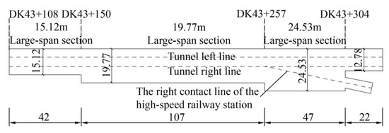
Figure 1.
Tunnel right contact line plan (unit: m).
3. Numerical Simulation Analysis of Construction Scheme
3.1. Numerical Calculation Model
The three-dimensional model of the tunnel was established using Midas GTS/NX 2019 finite element software. The model is established concerning the actual situation and according to the Saint-Venant’s principle to prevent the adverse effects of boundary constraints on the calculation [28,29,30]. The numerical model is 100 m in the longitudinal direction, 70 m in the transverse direction, and the distance between the center of the tunnel section and the bottom is 26 m. The Mohr–Coulomb elastic–plastic constitutive model is used for numerical calculation. The model is meshed using eight-node tetrahedral elements, with 145127 nodes and 106045 elements, as shown in Figure 2. When conducting static state simulation analysis, only the effect of self-weight is considered, and the impact of tectonic stress on the supporting structure and surrounding rock is not considered. Therefore, horizontal and vertical constraints are set at the bottom and left and right sides of the model. The surrounding rock and initial support parameters are determined based on the geological survey report and current specifications. The relevant calculation parameters are shown in Table 1.
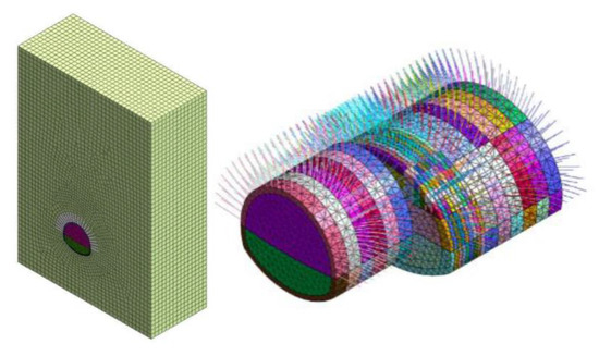
Figure 2.
The three-dimensional numerical calculation model.

Table 1.
Numerical model calculation parameter.
The choice of tunnel excavation scheme will affect the stress and deformation of the surrounding rock and the stress state of the supporting structure. According to the actual engineering conditions of the tunnel, this paper conducts numerical simulations on two construction methods—the three-bench method and the double-side-drift method—to study and analyze the stress, displacement, and change rules of the plastic zone of the surrounding rock. The pre-designed initial support steel arch frame is I20b@0.6 m. The diameter of the mesh reinforcement is 8 mm, and the size is 0.2 m × 0.2 m. The design strength grade of concrete is C25. The shotcrete thickness is 27 cm after completing the steel arch and mesh layout. A 4 m hollow anchor rod with a diameter of 22 mm is installed on the arch roof, and the load-bearing capacity of each anchor is 280 kN. The temporary support is made of the I18 steel frame. The construction step is 2 m, and the shotcrete lags behind one construction procedure.
3.2. Analysis of Lining Stress
Since the supporting structure and the surrounding rock are in contact with each other, their deformation is coordinated. The bending moment cloud diagram of the initial support after the tunnel is penetrated is extracted to study its stress situation, as shown in Figure 3.
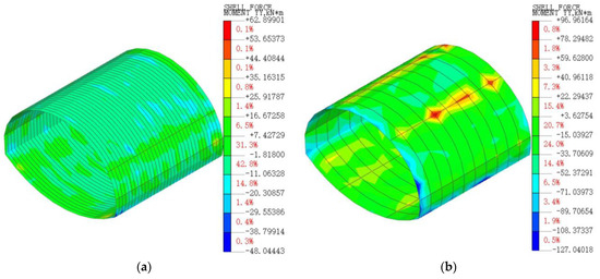
Figure 3.
Contour of initial support bending moment (unit: kN·m): (a) bench method, (b) double-side-drift method.
It can be seen from Figure 3 that the maximum positive bending moment is located at the left arch waist position after the bench method construction is completed. The maximum negative bending moment is located at the right arch foot and the bending moment values are 62.90 kN·m and 48.04 kN·m, respectively. After constructing the double-side-drift method, the maximum positive bending moment is located at the arch roof position. The maximum negative bending moment value is located at the right arch waist position. Its values have greatly increased compared with the bench method, with increases of approximately 50.5% and 23.7%, respectively. The stress changes at the temporary support of the two construction methods are large, indicating that the support has strengthened its bearing on the stress of the supporting structure. Therefore, the surrounding rock deformation is relatively small, which also causes the stress of the supporting structure to increase.
In order to further study the stress of the anchor during tunnel construction, the full-section axial force cloud diagram of the bolt was analyzed. It can be seen from Figure 4 that in the bench method, the maximum tensile stress of the anchor occurs at the arch spandrel position, with a value of 282.54 kN. The compressive stress is mainly distributed at the top of the bolt close to the surrounding rock. The maximum tensile force occurs at the arch roof in the double-side-drift method, and the tensile stress is significantly reduced compared with the bench method. The maximum compressive stress appears at the arch roof position. During the construction of the two methods, the bolt force of the anchor structure showed negative values. The maximum negative value of the double-side-drift method increased by approximately 66% compared with the bench method. It shows that the anchor rod of the double-side-wall heading method is more compressed, which will threaten the safety of the supporting structure.
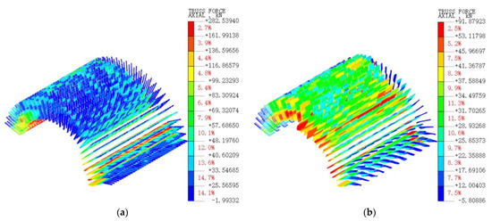
Figure 4.
Contour of anchor axial force (unit: kN): (a) bench method, (b) double-side-drift method.
3.3. Analysis of Surrounding Rock Displacement
The data of the displacement changes of the arch roof, arch waist, and arch foot with the construction procedures of the DK43 + 190 large-span section were selected, as shown in Figure 5. It can be seen from the figure that the time history curve of the arch roof settlement of the two construction methods shows an “S”-shaped development trend. The displacement begins to occur during the tunnel excavation. When the tunnel face advances to the selected section, the deformation changes drastically. When the tunnel face moves away from the selected section, the displacement changes in amount and the rate gradually decreases until it becomes stable. The time history curve of the convergence of the arch waist and the arch foot shows a “U”-shaped development trend. The convergence occurs during tunnel excavation, and the speed gradually increases. When the excavation face advances to the selected section, the convergence value reaches the maximum. When the excavation face is far from the selected section, the convergence increases in the opposite direction until it becomes stable. In the bench method, the maximum settlement position is at the arch roof, and its value is 30.04 mm. The maximum convergence position is at the arch foot, and its value is 2.53 mm. In the double-side-drift method, the maximum settlement position is at the arch roof, and its value is 21.09 mm. The maximum convergence position is at the waist of the arch, and its value is 5.89 mm. Since the number of procedures in the two compared construction methods is slightly different, and the time it takes for the excavation face to reach the selected section is also different, the bench method will have a greater impact on the displacement of the surrounding rock when excavating the target section. This also shows that the bench method is more beneficial to the stability of the surrounding rock in front of the excavation section. In terms of controlling the arch roof settlement, the double-side-drift method is better than the bench method, and the settlement value is 29.8% smaller than the bench method. The double-side-drift method is slightly better than the bench method in controlling deformation, but it has many construction procedures and higher construction costs [31].
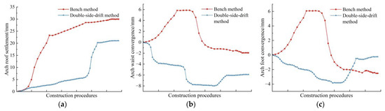
Figure 5.
Displacement time history curve: (a) arch roof settlement, (b) arch waist convergence, (c) arch foot convergence.
3.4. Analysis of Plastic Zone of Surrounding Rock
During the tunnel excavation process, the surrounding rock mass around the tunnel will be continuously disturbed. Therefore, it is necessary to analyze the changes in the plastic zone during excavation to ensure safe tunnel construction. The distribution of plastic zones at the completion stage of excavation is shown in Figure 6.
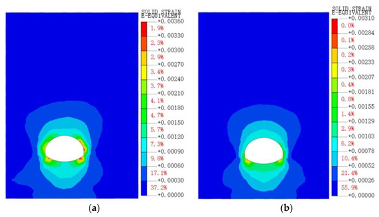
Figure 6.
Distribution contour of plastic zone: (a) bench method, (b) double-side-drift method.
It can be seen from Figure 6 that the extreme plastic strain values of the bench method and the double-side-drift method are 0.0036 and 0.0032, respectively. The extreme plastic strain values of the two construction methods are the same. The plastic zones of both construction methods are distributed around the tunnel excavation surface. The distribution range is relatively symmetrical. There is no bias phenomenon and no penetration of the plastic zones. The plastic zone of the bench method is mainly distributed at the arch waist and arch feet on both sides. The plastic zone of the double-side-drift method is mainly distributed at the arch foot on both sides. It shows that both construction methods can effectively inhibit the development of the plastic zone of the surrounding rock.
The above analysis shows that the two construction methods have their advantages during construction. This project has the characteristics of deep burial, complex stress on surrounding rocks, and a large excavation section. On the premise of ensuring construction safety, it is particularly important to choose a feasible construction method. Therefore, based on the analysis results of surrounding rock deformation and stress, it is recommended to adopt the bench method for construction. During construction, the stress monitoring of the arch spandrel and arch foot positions should be strengthened.
4. Optimization Analysis of Construction Scheme
Based on the previous numerical simulation results and construction suggestions, a step-by-step excavation was carried out according to the construction sequence. The small-span and large-span sections were excavated using the two-bench and three-bench methods, respectively, with a construction step of 2 m. The initial support is carried out after tunnel excavation and bolt reinforcement. The secondary lining is constructed after the excavation and support of each construction section is completed. At the same time, there are problems, such as the technical complexity of removing vertical supports and the inability to implement advanced support during construction. A method of setting up transition sections in the variable cross-section was proposed. The three-bench temporary inverted arch method is used for excavation, and the construction step is set to 0.6 m. During construction, it was found that this method could meet the tunnel excavation requirements to a certain extent. However, due to insufficient construction space at the variable cross-section of the tunnel, there are certain difficulties in converting between different construction methods. Moreover, connecting the supporting structures between different spans is difficult, which seriously affects the progress and quality of tunnel excavation and is prone to collapse and other safety issues.
To solve the above problems, it was decided to optimize the excavation method of the upper step. The design of the optimization scheme should minimize dependence on geological conditions while ensuring that it meets the engineering requirements. Considering the detachability and positional adjustability of the temporary support structure, frequent construction method changes in a limited working space should be avoided. At the same time, it is also necessary to ensure the operability of the monitoring system. The performance of surrounding rock and supporting structures during construction is mastered. Regarding the research results of some scholars [32,33,34,35], combined with previous construction experience and other factors, two optimized excavation schemes for the upper step were proposed. Scheme Ⅰ is the supporting portal method, and Scheme Ⅱ is the bench method similar to the main hole. The stress, displacement, and plastic zone distribution of the surrounding rock of the two optimization schemes were analyzed via numerical simulation to determine a reasonable construction scheme.
4.1. The Construction Procedures of the Upper Step Expansion Excavation Method
Scheme Ⅰ is shown in Figure 7a, and the construction procedure is as follows. (1) Complete the excavation of the small-span section and the establishment of secondary lining. (2) Set up an advanced support structure around pilot tunnel ① for pre-reinforcement, excavate pilot tunnel ①, and construct upper anchors and initial support. (3) Excavate pilot tunnel ② and provide upper anchors and initial support. (4) Excavate pilot tunnel ③ laterally, with an excavation depth of 1 m, erect a door frame, spray concrete, and install anchor tubes at the arch foot. (5) Excavate large-span sections and construct supporting structures.
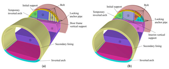
Figure 7.
Schematic diagram of expanding excavation methods: (a) Scheme Ⅰ, (b) Scheme Ⅱ.
Scheme Ⅱ is shown in Figure 7b, and the construction procedure is as follows. (1) Complete the excavation of the small-span section and the establishment of secondary lining. (2) Set up an advanced support structure around pilot tunnel ① for pre-reinforcement, excavate the pilot tunnel ①, and construct upper anchors and initial support. (3) Excavate pilot tunnel ②, and form a right-turn door opening with vertical supports and arches. (4) Excavate pilot tunnel ③-1 at one time and reserve steps for the side wall. (5) Excavate pilot tunnel ③-2 and apply lining to form a closed support structure. (6) Excavate the large-span section and construct a supporting structure.
4.2. Analysis of Surrounding Rock Stress
Figure 8 shows the stress distribution of the surrounding rock at y = 14 m during the construction of the upper right part of the transition section under the two schemes. Through comparison, when the two schemes are completed, the overall stress distribution is similar. In Scheme Ⅰ, the stress value on the upper free surface is smaller, and the stress distribution is relatively uniform. In Scheme Ⅱ, two stress concentrations appear on the tunnel face, with the maximum stress value being 0.77 MPa. The results show that both expansion and excavation methods have good effects on controlling the stress of surrounding rock. However, Scheme Ⅰ has a more stable stress distribution than Scheme Ⅱ and can better solve the stress concentration phenomenon.
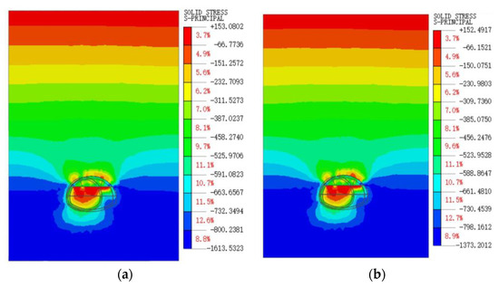
Figure 8.
Stress contour at y = 14 m after excavation support is completed (unit: MPa): (a) Scheme Ⅰ, (b) Scheme Ⅱ.
4.3. Analysis of Lining Stress
It can be seen from Figure 9 that when using Scheme Ⅰ, the lining is squeezed by the surrounding rock. As a result, there is a relatively obvious stress concentration phenomenon here. The maximum value is distributed at the connection between the arch foot and the surrounding rock, approximately 21.53 MPa. The minimum principal stress is located at the junction of the upper and lower steps of the large-section excavation, indicating that the junction bears greater principal stress. When using Scheme Ⅱ, the location where the maximum principal stress occurs is the same as Scheme Ⅰ. Its value is approximately 29.36 MPa. The minimum principal stress appears at the upper step lining. After the excavation of the transition section is completed, the tensile stress appears in the upper part of the lining, and the stress distribution is uneven. Comparing the two schemes, adopting Scheme Ⅰ in the transition section can make the lining stress distribution more uniform. And tensile stress is only generated at the lining connection. At the same time, it is necessary to strengthen monitoring during the excavation process to ensure construction safety.
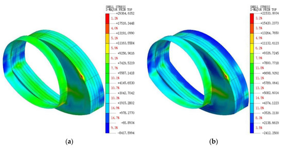
Figure 9.
The maximum principal stress cloud diagram of the upper right part of the transition section (unit: MPa): (a) Scheme Ⅰ, (b) Scheme Ⅱ.
4.4. Analysis of Surrounding Rock Deformation
The vertical displacement at the variable cross-section was selected to analyze the effects of the two schemes on the vertical displacement of the surrounding rock. From Figure 10, the displacement of the upper right part of the variable-section tunnel after the completion of construction can be obtained. The convergence values of the arch waist and arch foot caused are 6.33 mm and 2.04 mm, respectively, and the settlement value of the arch roof is 1.34 mm by adopting Scheme Ⅰ. The convergence values of the arch waist and arch foot caused are 7.20 mm and 4.20 mm, respectively, and the settlement value of the arch roof is 5.02 mm by adopting Scheme Ⅱ. It can be seen that the convergence and settlement values caused by Scheme Ⅰ are smaller than those of Scheme Ⅱ, and the development is relatively gentle. Therefore, using Scheme Ⅰ can achieve a better control of surrounding rock deformation.

Figure 10.
Vertical displacement curves of transition section construction.
4.5. Analysis of Plastic Zone of Surrounding Rock
It can be seen from Figure 11 that the plastic strain extreme value of the two schemes after the completion of the variable cross-section construction are 0.0169 and 0.0175, respectively. The plastic zone is mainly distributed in the initial excavation section of the small section, the transition section, and the excavation face of the large section. Through comparison, it is found that Scheme Ⅰ is more effective in inhibiting the development of the plastic zone of the surrounding rock in the transition section. This situation will be more beneficial to the stability of the surrounding rock.
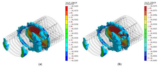
Figure 11.
Distribution contour of plastic zone: (a) Scheme Ⅰ, (b) Scheme Ⅱ.
From the above analysis, the two expansion schemes can effectively connect the excavation working surface. The problem of the inability to implement advanced support is effectively solved. However, by comparing the numerical simulation results of the two options, it is found that Scheme Ⅰ can better suppress the deformation and stress changes of the surrounding rock. Therefore, Scheme Ⅰ (supporting portal method) was used to expand the upper steps at the variable cross-section of tunnel.
5. Field Monitoring Measurement Analysis
5.1. Field Monitoring Scheme
To understand the deformation and stress characteristics of the surrounding rock during the construction of the variable cross-section tunnel, the tunnel section was monitored based on the actual conditions on-site. The monitoring content and frequency of each monitoring section refer to relevant specifications [36]. The arrangement of monitoring points is shown in Figure 12. The selection of monitoring sections is shown in Table 2. The same section points were arranged in the same mileage plane to ensure the accuracy of monitoring results. The measuring points of different sections should be at the same position.
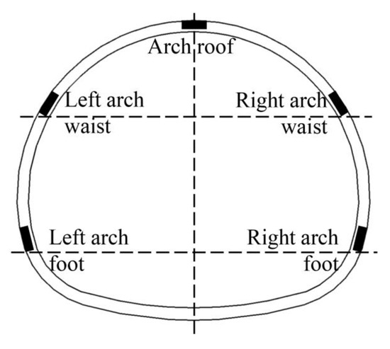
Figure 12.
Surrounding rock displacement monitoring point layout diagram.
Table 2.
Monitoring measurement section selection.
5.2. Analysis of Displacement Monitoring
Figure 13 is the variation law of the settlement value of the arch roof of each section during the construction process, which is similar. Both increase sharply in the early stage as the tunnel excavation face advances, increase slowly in the mid-term, and stabilize about 28 days after construction and excavation. The final values of arch roof settlement of each construction section are distributed in the range of 15.90 mm to 19.27 mm, 12.09 mm to 17.20 mm and 15.01 mm to 21.41 mm. After the tunnel is penetrated, the differences between the maximum and minimum arch roof settlement values of each construction section are 17.48%, 29.66%, and 29.92%, respectively. The differences in the extreme arch roof settlement values of the transition section and the large-span section are similar and larger than the small-span section.
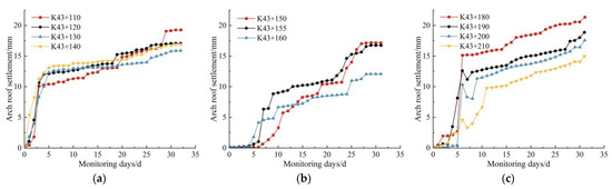
Figure 13.
Time history curve of arch roof settlement displacement: (a) small-span section, (b) transitional section, (c) large-span section.
It can be seen from Figure 14 that the waist convergence value in different construction sections increases sharply within 0 to 6 days and slowly increases within 7 to 16 days. Finally, the levels gradually converged and stabilized after 17 days. After the tunnel was penetrated, the arch waist convergence values of the three construction sections stabilized in the range of 9.90 mm to 15.58 mm, 3.24 mm to 5.31 mm, and 5.76 mm to 14.55 mm, respectively. The differences between the minimum and maximum values are 36.52%, 38.86%, and 56.49%, respectively. The difference between the arch waist convergence extreme values of the small-span section and the transition section is equal, and both are smaller than that of the large-span section.
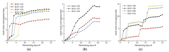
Figure 14.
Time history curve of arch waist convergence displacement: (a) small-span section, (b) transitional section, (c) large-span section.
The conversion of different section-surface construction methods will cause large changes in the displacement at the arch foot. The convergence at the arch foot of each section of the two construction sections, the variable cross-section, and the large-span section was analyzed. The time history curve of monitoring displacement is shown in Figure 15. The changing trend of the arch foot convergence value of each section is the same as the changing trend of the arch roof settlement and arch waist convergence. As the tunnel excavation face advances, the arch foot convergence value shows a trend of rapid increase in the early stage, slow increase in the middle stage, and gradually stable in the later stage. The final values of arch foot convergence for the variable cross-section and the large-span section are distributed in the range of 1.30 mm to 3.16 mm and 0.84 mm to 13.52 mm.
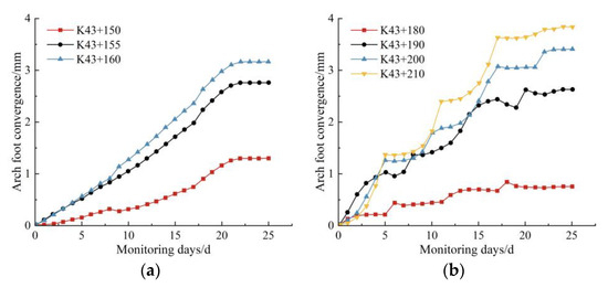
Figure 15.
Time history curve of arch foot convergence displacement: (a) transitional section, (b) large-span section.
The field monitoring results were compared with the numerical simulation results. The comparison results are shown in Table 3.
Table 3.
Comparison of field monitoring and numerical simulation value (unit: mm).
Simplifications and assumptions were made during the numerical simulation calculations. In actual tunnel excavation, there are often joints, cracks, and structural stresses in the surrounding rock, which results in a certain gap between the field monitoring data and the numerical simulation results. However, it can be seen from Table 3 that the small numerical difference does not affect the change pattern of the three groups of displacements, which also verifies the rationality of the numerical simulation. At the same time, the use of lateral supports in the construction method inhibits the horizontal displacement of the surrounding rock. The arch foot convergence value of each section is smaller than its arch roof settlement and arch waist convergence values. The difference in field monitoring data for arch foot convergence is smaller than that between arch roof settlement and arch waist convergence. It also shows that the numerical simulation results of the convergence of the arch waist and the arch foot are closer to the real construction situation.
6. Conclusions
According to actual tunnel engineering, the mechanical effects of large-span variable cross-section tunnels using different construction schemes were analyzed through numerical simulation. An optimized construction scheme was proposed to make the construction more safe and rapid based on the research results. The conclusions are as follows:
- (i)
- Based on the results of numerical simulation analysis, it is proposed to set up a transition section at the variable cross-section position. The three-step temporary inverted arch method is used for construction. It was found that this solution could reduce the vertical displacement of the arch roof in the variable cross-section section during excavation. Establishing horizontal braces can better control the horizontal displacement of the excavation tunnel face, and there is no large-area stress concentration. Due to the headwall at the variable cross-section, the displacement of the right side wall at the variable cross-section will increase. The deformation of the right side wall of the widened section is weakened.
- (ii)
- In view of the difficulties in tunnel construction, two optimized expansion excavation methods were analyzed, and the support portal method was selected for construction. Through field implementation, it was found that this method can better connect the excavation working surface and can also solve the problem of inability to implement advanced support. No surrounding rock collapse occurred during the construction process, effectively suppressing the deformation and stress changes caused by the excavation of the tunnel face.
- (iii)
- Through the compilation and analysis of field monitoring data, it was found that the changes in the surrounding rock arch roof settlement, arch waist, and arch foot convergence tend to be consistent. All showed a trend of rapid increase in the early stage, slowing down in the mid-term, and gradually stabilizing in the later stage. The feasibility and rationality of the numerical simulation results and optimized construction scheme were verified. It solves the problem of stress concentration and deformation of surrounding rocks near the variable cross-section position of the tunnel that is difficult to control.
In general, the numerical calculation on a variable cross-section of a railway tunnel was conducted in the study, and the construction scheme adopted can provide a reference for similar projects. However, the stability of surrounding rock in variable cross-section tunnels is related to many parameters. At the same time, factors such as geological conditions and in situ stress will also impact the stability of the surrounding rock. Further research is needed on constructing the variable cross-section of deeply buried tunnels under high-ground stress. Moreover, the field monitoring of the surrounding rock should be strengthened to ensure safe and efficient tunnel construction in complex geological environments.
Author Contributions
Writing—original draft S.S. and Y.L.; Resources S.L. and Z.S. (Ziyi Song); Formal analysis S.L.; Data curation Y.L.; Methodology R.H.; Writing—review and editing R.H. and Z.S. (Zhanping Song); Funding acquisition R.H.; Project administration Z.S. (Zhanping Song); Visualization S.S. and Z.M.; Software Z.M. and Z.S. (Ziyi Song). All authors have read and agreed to the published version of the manuscript.
Funding
The authors declare financial support was received for the research, authorship, and/or publication of this article. This work was supported by the Open Fund of State Key Laboratory of Frozen Soil Engineering (SKLFSE202107).
Data Availability Statement
The data presented in this study are available on request from the corresponding author. The data are not publicly available due to privacy.
Conflicts of Interest
Author Shuguang Li was employed by the company Post-Doctoral Research Workstation, China Railway 20th Bureau Group Co., Ltd., and Author Ziyi Song was employed by the company Henan Provincial Communications Planning & Design Institute Co., Ltd. The remaining authors declare that the research was conducted in the absence of any commercial or financial relationships that could be construed as a potential conflict of interest.
References
- Fan, S.; Song, Z.; Xu, T.; Wang, K.; Zhang, Y. Tunnel deformation and stress response under the bilateral foundation pit construction: A case study. Arch. Civ. Mech. Eng. 2021, 21, 109. [Google Scholar] [CrossRef]
- Song, S.; Huo, R. Optimization Research and Application of Empty Hole Straight Cut Blasting Scheme for Railway Tunnel. Blasting 2023, in press. Available online: https://link.cnki.net/urlid/42.1164.TJ.20231024.1328.002 (accessed on 16 October 2023).
- Editorial Department of China Journal of Highway and Transport. Review on China’s Traffic Tunnel Engineering Research: 2022. China J. Highw. Transp. 2022, 35, 1–40. [Google Scholar] [CrossRef]
- Zhao, Y.; Li, P. A statistical analysis of China’s traffic tunnel development data. Engineering 2018, 4, 3–5. [Google Scholar] [CrossRef]
- Zhu, Y.; Zhou, J.; Zhang, B.; Wang, H.; Huang, M. Statistical analysis of major tunnel construction accidents in China from 2010 to 2020. Tunn. Undergr. Space Technol. 2022, 124, 104460. [Google Scholar] [CrossRef]
- Sousa, R.; Einstein, H. Lessons from accidents during tunnel construction. Tunn. Undergr. Space Technol. 2021, 113, 103916. [Google Scholar] [CrossRef]
- Wang, X.; Lai, J.; Qiu, J.; Xu, W.; Wang, L.; Luo, Y. Geohazards, reflection and challenges in mountain tunnel construction of China: A data collection from 2002 to 2018. Geomat. Nat. Hazards Risk 2020, 11, 766–785. [Google Scholar] [CrossRef]
- Tian, X.; Song, Z.; Zhang, Y. Monitoring and reinforcement of landslide induced by tunnel excavation: A case study from Xiamaixi tunnel. Tunn. Undergr. Space Technol. 2021, 110, 103796. [Google Scholar] [CrossRef]
- Zhao, F. Study on Mechanical Behavior and Surrounding Rock Classification of Variable Cross-Section Double-Line Parallel Metro Tunnels. Master’s Thesis, Shijiazhuang Tiedao University, Shijiazhuang, China, 2020. [Google Scholar]
- Wang, Y. Study on Construction Mechanics of Shallow-Buried Large-Span Variable Section Subway Tunnel Group. Master’s Thesis, Shandong University, Jinan, China, 2018. [Google Scholar]
- Guo, H.; Chen, L.; Zhang, L.; Wang, Z.; Zhong, D.; Yang, L. Deformation Characteristics and Reinforcement Methods in Variable Cross-section at Emergency Parking Belt in Soft Rock Mass Highway Tunnel. Sci. Technol. Eng. 2022, 22, 15765–15774. [Google Scholar]
- Taromi, M.; Eftekhari, A.; Hamidi, J.; Aalianvari, A. A discrepancy between observed and predicted NATM tunnel behaviors and updating: A case study of the Sabzkuh tunnel. Bull. Eng. Geol. Environ. 2017, 76, 713–729. [Google Scholar] [CrossRef]
- Wang, T.; Zhu, Y.; Tian, X.; Shi, F.; Zhang, L.; Lu, Y. Design method of the variable cross-section tunnel focused on improving passenger pressure comfort of trains intersecting in the tunnel. Build. Environ. 2022, 221, 109336. [Google Scholar] [CrossRef]
- Zhang, Y.; Tao, L.; Liu, J.; Zhao, X.; Guo, F.; Tan, L.; Wang, Z. Construction techniques and mechanical behavior of newly-built large-span tunnel ultra-short distance up-crossing the existing shield tunnel with oblique angle. Tunn. Undergr. Space Technol. 2023, 138, 105162. [Google Scholar] [CrossRef]
- Zeng, W.; Peng, X.; Zhang, L.; Hu, E.; Yang, W. Mechanical Characteristics of Super-Large Variable-Section Tunnel. Chin. J. Undergr. Space Eng. 2022, 18, 2062–2071+2079. [Google Scholar]
- Yao, G.; Jin, Y. Study on mechanical characteristics of large section tunnel construction in soft surrounding rock. In Proceedings of the 2021 International Conference on Smart Transportation and City Engineering, Chongqing, China, 26–28 October 2021; SPIE: Bellingham, WA, USA, 2021; Volume 12050, pp. 1040–1046. [Google Scholar] [CrossRef]
- Luo, J.; Zhang, D.; Fang, Q.; Liu, D.; Xu, T. Mechanical responses of surrounding rock mass and tunnel linings in large-span triple-arch tunnel. Tunn. Undergr. Space Technol. 2021, 113, 103971. [Google Scholar] [CrossRef]
- Yang, D.; Qian, K.; Tong, J.; Gui, D.; Wang, M. Study on Mechanical Characteristics of Super-large Section Highway Tunnel during Construction Methd Change. Mod. Tunn. Technol. 2021, 58, 216–223. [Google Scholar]
- Wu, K.; Yu, Y.; Cui, S.; Zhang, Q. Construction mechanical mechanism of shallow subway tunnel group with large-span variable cross section. Geotech. Geol. Eng. 2018, 36, 3879–3891. [Google Scholar] [CrossRef]
- Zhu, Y.; Chen, L.; Zhang, H.; Zhou, Z.; Chen, S. Physical and mechanical characteristics of soft rock tunnel and the effect of excavation on supporting structure. Appl. Sci. 2019, 9, 1517. [Google Scholar] [CrossRef]
- Xu, J.; Xie, X.; Shi, Z.; Cai, W.; Xu, D.; Xu, C. Experimental study on performance of spring damping support structure system for large deformation tunnel in soft rock. Undergr. Space 2023, in press. [CrossRef]
- Wang, X.; Zhao, W.; Wu, S. Tunnel Support Structure System and Its Synergy. J. World Archit. 2023, 7, 11–16. [Google Scholar] [CrossRef]
- Fan, S.; Song, Z.; Li, X.; Zhang, Y.; Liu, L. Investigation into the Large Deformation Mechanism and Control Technology of Variable Cross-Section Tunnel in Layered Mudstone Stratum. Buildings 2022, 13, 110. [Google Scholar]
- Zhou, Z.; Zhao, J.; Tan, Z.; Zhou, X. Mechanical responses in the construction process of super-large cross-section tunnel: A case study of Gongbei tunnel. Tunn. Undergr. Space Technol. 2021, 115, 104044. [Google Scholar] [CrossRef]
- Qiao, S.; Cai, Z. Study on the Characteristics of Surrounding Rock-support in Variable Cross Section Construction of Extra-long Highway Tunnel. Chin. J. Undergr. Space Eng. 2021, 17, 275–282. [Google Scholar]
- Yang, C.; Wei, L.; Mo. H.; Chen, J. Mechanical Response of Immersed Tunnel with Variable Section during Temporary Support. Chin. J. Undergr. Space Eng. 2020, 16, 1504–1510+1562. [Google Scholar]
- Luo, Y.; Chen, J.; Shi, Z.; Li, J.; Liu, W. Mechanical characteristics of primary support of large span loess highway tunnel: A case study in Shaanxi Province, Loess Plateau, NW China primary. Tunn. Undergr. Space Technol. 2020, 104, 103532. [Google Scholar] [CrossRef]
- Zhou, H.; He, C.; Wang, X.; Chen, Y.; Li, J. Assessment of the seismic response of shallow buried elliptical tunnels. J. Earthq. Eng. 2023, 27, 465–487. [Google Scholar] [CrossRef]
- Tang, B.; Cheng, H.; Tang, Y.; Zheng, T.; Yao, Z.; Wang, C.; Rong, C. Supporting design optimization of tunnel boring machines-excavated coal mine roadways: A case study in Zhangji, China. Processes 2020, 8, 46. [Google Scholar] [CrossRef]
- Yang, T.; Xiong, S.; Liu, S.; Liu, Y.; Zhao, H.; Li, Y. Numerical analysis of the influence of deep foundation pit construction on adjacent subway stations in soft soil areas. Adv. Civ. Eng. 2022, 2022, 6071868. [Google Scholar] [CrossRef]
- Tian, X.; Song, Z.; Wang, H.; Zhang, Y.; Wang, J. Evolution characteristics of the surrounding rock pressure and construction techniques: A case study from Taoshuping tunnel. Tunn. Undergr. Space Technol. 2022, 125, 104522. [Google Scholar]
- Jia, Y.; Xia, Y.; Chen, X.; Zhou, Y.; Han, X.; Zhou, S. Force and deformation characteristics during the reconstruction and expansion of shallow single-tube tunnels into large-span multiarch tunnels. Adv. Mater. Sci. Eng. 2019, 2019, 2783784. [Google Scholar] [CrossRef]
- Vetter, S.; Galli, M.; Steiner, P. Refurbishment of the Kuckuckslay tunnel–Current experience in the use of the “Tunnel-im-Tunnel-Methode”. Geomech. Tunn. 2020, 13, 557–565. [Google Scholar] [CrossRef]
- Naghadehi, M.Z.; Thewes, M.; Lavasan, A.A. Face stability analysis of mechanized shield tunneling: An objective systems approach to the problem. Eng. Geol. 2019, 262, 105307. [Google Scholar] [CrossRef]
- Kim, K.Y.; Jo, S.A.; Ryu, H.H.; Cho, G.C. Prediction of TBM performance based on specific energy. Geomech. Eng. 2020, 22, 489–496. [Google Scholar] [CrossRef]
- Q/CR9218-2015; Technical Specification for Monitoring Measurement of Railway Tunnel. Standardization Administration of the People’s Republic of China: Beijing, China, 2015.
Disclaimer/Publisher’s Note: The statements, opinions and data contained in all publications are solely those of the individual author(s) and contributor(s) and not of MDPI and/or the editor(s). MDPI and/or the editor(s) disclaim responsibility for any injury to people or property resulting from any ideas, methods, instructions or products referred to in the content. |
© 2023 by the authors. Licensee MDPI, Basel, Switzerland. This article is an open access article distributed under the terms and conditions of the Creative Commons Attribution (CC BY) license (https://creativecommons.org/licenses/by/4.0/).