Abstract
To study the seismic strengthening of damaged reinforced concrete (RC) frames using CFRP sheets, this study designed and tested the scaled 2-bay and 2-storey RC frame specimens. After applying a low cyclic horizontal load to simulate the initial damage to the specimen in an earthquake disaster, CFRP was used to strengthen the joints of the damaged RC frame. Pseudo-static tests of strengthened specimens and counterpart specimens were then carried out. Seismic performance, including stiffness, load capacity, ductility and energy dissipation were further analyzed. The failure mode of strengthened RC frame structures showed excellent ductility. The results demonstrated that the strengthening method involving wrapping CFRP can significantly improve the maximum horizontal bearing capacity, initial stiffness and energy dissipation capacity of the non-ductile reinforced concrete frame structure. The average displacement ductility coefficient of strengthened specimen can be enhanced to 3.41 compared with that of counterpart specimen (3.00). The pushover analysis based on the OpenSees model determined that the prototype frame with CFRP strengthening can maintain structural integrity and safety, with its maximum interstorey displacement angle below the limit of seismic specification (i.e., 1/50 in a severe earthquake). This study can contribute to the development of practical and efficient methods for restoring and improving the performance of damaged RC frames in seismic-prone regions.
1. Introduction
In recent years, Fiber Reinforced Polymer (FRP) has been widely applied to the seismic strengthening of reinforced concrete (RC) structures due to its advantages of being lightweight, strong, corrosion resistant and enabling easy construction [1,2,3]. The FRP strengthening method has the advantage of facilitating effective construction and economic retrofitting without occupying too much space [4,5]. Various countries have successively promulgated and implemented the FRP strengthening technical regulations, mainly for reinforced concrete (RC) members. The FEMA-P-695 report [6] collected the latest research results in the field of earthquake engineering in the United States, including ground motion record database, new generation attenuation relation and probabilistic seismic risk analysis results, structural nonlinear modeling and analysis methods, structural collapse numerical simulation methods, and uncertainty modeling and analysis. A scientific and reasonable probabilistic seismic performance evaluation method has been developed to evaluate whether the existing structure can meet the expected collapse-resistant performance objective.
Research on FRP in the seismic reinforcement of concrete structures focuses mainly on the pseudo-static test of beam and column members. Katsumata et al. [7] applied FRP to the seismic reinforcement of RC columns. To study the effect of reinforcement, the authors conducted experiments on low cyclic hysteresis of 15 specimens with a scale ratio of 1:4 after strengthening with FRP. Saadatmanesh et al. [8] applied GFRP to the seismic reinforcement of circular RC columns and conducted a study on the seismic performance of five circular RC columns with a 1:5 scaling ratio strengthened by GFRP. The analysis and test results showed that the seismic performance of reinforced GFRP columns significantly improved. Ye et al. [9] designed eight square RC columns with a cross-section size of 200 mm, used CFRP to strengthen the columns and studied their seismic performance. Analysis of the test results showed that the reinforcement effect was good, which could effectively improve the seismic performance of the columns. Richelle and Kawashima [10] reinforced six circular RC columns with CFRP and proposed a simulated model to investigate the hysterical behavior of RC columns constrained by FRP. A seismic strengthening design of a prototype bridge column was also developed.
The mechanical behavior of frame joints strengthened with FRP is more complex. Ghobarah and Said [11] used GFRP to strengthen T-shaped beam-column joints and conducted a comparative test of hysteretic performance compared with unreinforced T-shaped joints. The experimental results showed that the shear strength and ductility of T-shaped joints improved significantly, and the shear failure mode of T-shaped joints could be prevented. Wang et al. [12,13] carried out tests to demonstrate the efficiency of a semi-active turned mass damper with variable stiffness and damping. Antonopoulos et al. [14] used FRP to strengthen 18 T-shaped beam-column joints with a 2:3 scaling ratio and conducted performance tests on the strengthened joints. The influences of FRP bonding form, axial compression ratio, joint reinforcement ratio, initial damage, different FRP types (i.e., CFRP and GFRP) and beam stirrup on the reinforcement were analyzed.
In addition to the application of FRP in strengthening structural members and joints, the performance of FRP-strengthened frames has been investigated by many scholars. Duong et al. [15] studied the seismic performance of the low ductility frame reinforced with CFRP and found that the CFRP can effectively improve the bearing capacity, ductility and energy dissipation capacity of the frame. El-Sokkary and Galal [16] used finite element analysis to study the reinforcement effectiveness of the existing non-ductile RC frame structures using different reinforcement methods, and the analysis showed that the seismic resistance of the whole structure can be effectively improved by wrapping the beams and columns with FRP. Shaikh et al. [17] investigated the structural characteristics of the frame by wrapping both column and beam fractures with CFRP. The retrofitted RC frames are evaluated based on global and local performance. Ali et al. [18] assessed the effectiveness of applying FRP-strengthening technology to enhance the seismic performance of the RC frame. The results confirmed a significant increase in the reliability of the RC frame due to FRP-flexural/FRP-confinement strengthening. Many scholars (Rousakis et al. [19,20], Fanaradelli et al. [21,22,23], Anagnostou et al. [24]) have demonstrated that the hybrid approach that combines powerful three-dimensional finite element models with other powerful analytical models such as MCFT can provide additional solid information for design parameters.
The effectiveness of strengthening RC frames using CFRP has been proven in recent decades. However, most studies have focused on the reinforcement of undamaged reinforced concrete (RC) frames rather than addressing the specific challenges posed by already damaged RC frames. In fact, there is a need to retrofit the heavily damaged RC frames following earthquake disasters (Garcia et al. [25], Wattanapanich et al. [26], Muslum et al. [27], Attari et al. [28], Imjai et al. [29,30], Hanan et al. [31], Yang et al. [32]). However, relevant investigations on the seismic performance of damaged RC frames using CFRP strengthening are few and the results are weak and do not provide valuable suggestions for post-earthquake reconstruction and rehabilitation.
To fill the gap, this study experimentally and numerically investigated the seismic performance of strengthening damaged RC frame structures using CFRP sheets. In this study, the CFRP sheets were used in regions with potential plastic hinges. Pseudo-static tests of the scaled 2-bay and 2-storey RC frame specimens, including strengthened specimen and counterpart specimen, were first designed and then analyzed to identify the seismic capacity, including stiffness, load capacity, ductility and energy dissipation. The performance and effectiveness of the CFRP strengthening technique were then evaluated and reviewed. Furthermore, the macro-model was developed using OpenSees and used to analyze the behavior of the prototype structure strengthened with CFRP sheets. This study can promote the utilization of CFRP in practical engineering by providing valuable CFRP strengthening schemes.
2. Materials and Methods
2.1. Specimen Design
In this study, the prototype of a five-storey, two-span RC frame was designed based on the SATWE analysis, as shown in Figure 1. The overall height and width of the test frame were taken as 15,000 mm and 8000 mm, respectively. The cross sections of all the columns were 400 × 400 mm, whereas the cross sections of the beams were 300 × 400 mm. The elevation and reinforcement diagrams are shown in Figure 2. In this test, the bottom two layers of the frame were selected and the similarity ratio was set to 1:2. Figure 3 shows the outlines and reinforcement detailing of the specimens. The percentage of steel reinforcement required in column sections was 1.57%, while the percentage of steel reinforcement in the beam sections was 0.52% for tension and compression sections, respectively. Twelve-millimeter diameter reinforcements were used as column and beam stirrups at a constant spacing of 200 mm c/c. Two types of specimens were used: the strengthened type and its counterpart.
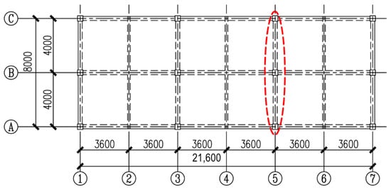
Figure 1.
Layout of the prototype structure (mm).
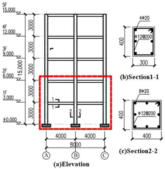
Figure 2.
Elevation and reinforcement of the prototype structure (mm).
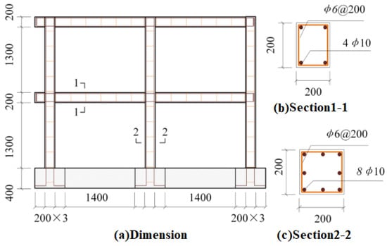
Figure 3.
Outline and reinforcement diagram of the RC frame in the test (mm).
The strengthening scheme was carried out based on the specifications described in [3], as shown in Figure 4. The detailed strengthening steps are as follows: (I) Surface treatment of the predetermined reinforcement section is carried out using a grinding machine, as shown in Figure 4a; (II) The roller in the bottom resin evenly coats the concrete surface of the predetermined reinforcement section, as shown in Figure 4b; Then the beam-column corners are chamfered—the chamfering radius is 20 mm; (III) Three layers of carbon fiber cloth are pasted over a 300 mm length. Specifically, the first layer is longitudinally pasted and then the second and third layers are circumferentially wrapped, as shown in Figure 4c.
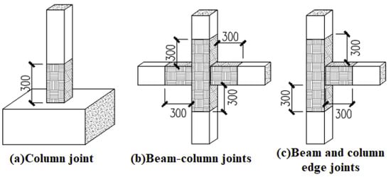
Figure 4.
Specimen reinforcement scheme (mm).
2.2. Material Properties
The compressive strength of the concrete cube at 28 days was 35.4 MPa on average. The elastic modulus and Poisson ratio of the prismatic concrete were 33,100 MPa and 0.23, respectively. The yield strength, elastic modulus and ultimate strength of rebars are listed in Table 1. The properties of CFRP sheets and impregnated adhesives are listed in Table 2.

Table 1.
Material properties of rebars.
Table 2.
Material properties of CFRP sheets.
2.3. Test Setup and Instrumentation
As shown in Figure 5, the test devices consisted of a reaction wall, a rigid floor, two vertical jacks, two horizontal electro-hydraulic servo actuators, a distribution beam and several ground anchors. The specimen was anchored to the rigid floor and tested using the vertical jacks and horizontal actuators. Two jacks combined with the distribution beam were used to apply vertical loads. Two electro-hydraulic servo actuators were used to apply horizontal loads. Both horizontal displacement and force were constantly monitored and recorded by the MTS electro-hydraulic servo loading system.
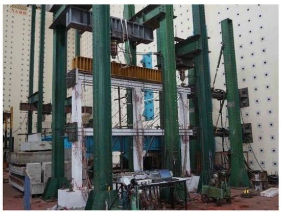
Figure 5.
Test setup and instrumentation.
2.4. Test Loading System
The specimen was subjected to a constant axial compression force and cyclic lateral loading. The cyclic lateral loading was applied based on ATC-24 (ATC1992) [33], as shown in Figure 6. The nominal lateral load capacity (Hn) of the specimen was estimated using the plastic stress distribution method. The elastic lateral loading cycles were initially conducted using force control, including two cycles at amplitudes of 0.25 Hn, 0.50 Hn and 0.75 Hn. When the first longitudinal bar of the specimen yielded, the specimen moved to the inelastic stage; then, the damaged specimen was strengthened according to the CFRP retrofitting scheme and further tested in the inelastic stage. Two lateral loading cycles were conducted using displacement control. Specifically, the displacement-controlled loading was adopted at amplitudes of 1Δ, 1.5Δ, 2Δ and so on. The experiment was terminated when the lateral resistance of the specimen was reduced to 85% of the maximum lateral load capacity.
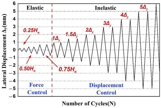
Figure 6.
Cyclic loading scheme.
3. Test Results and Analysis
The experimental observations and results of the specimens were analyzed further. The experimental results included cyclic lateral load-drift responses, lateral load capacity and stiffness, displacement ductility ratios and energy dissipation capacity.
3.1. Load-Drift Curves
After the test, the CFRP-strengthened specimen was severely damaged at the plastic hinge region of the column components. However, the plastic hinge regions of the beam components were only slightly damaged. For the counterpart specimen, the concrete was severely crushed at the plastic hinges of both the beams and the columns, which showed obvious insufficiency in ductility.
Figure 7a–d shows the storey shear versus storey drift at each storey. Figure 7e,f shows the base shear versus overall drift response (i.e., drift at the top of the specimens). When subjected to a loading amplitude of 3.5Δ, the counterpart specimen exhibited an inverse S-shaped hysteretic ring and the pinching phenomenon was obvious. The counterpart specimen showed more slip and shear failure. The hysteretic curves of the strengthened specimen were plumper than those of the counterpart specimen. This phenomenon suggests that the frames exhibit improved ductility and energy dissipation characteristics after experiencing earthquake damage and then being reinforced with CFRP wrapping.
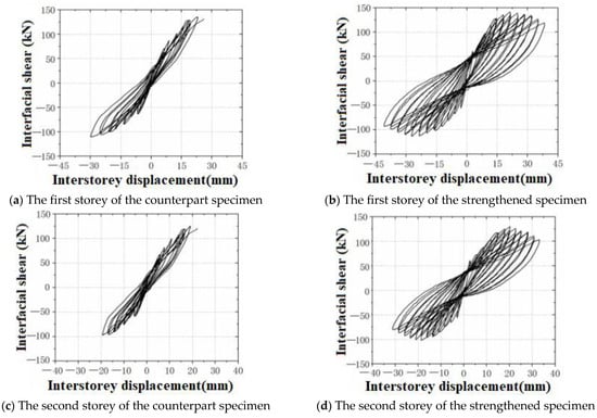
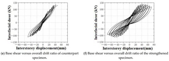
Figure 7.
Hysteresis curves of specimens.
Although each level of loading in the experiment was set as symmetric loading, the hysteretic curves of the two specimens showed asymmetric phenomena, indicating that the positive horizontal load was greater than the negative horizontal load. This is associated with the sequence of component failure and plastic hinge development in the frame.
3.2. Backbone Curve
In the pseudo-static test, the backbone curve can be obtained by connecting the peak points of each stage of hysteretic curve loading. Figure 8 compares the backbone curves of the strengthened specimen and its counterpart specimen. For the loading curves at each loading stage, the bearing capacity of strengthened specimens was slightly higher than that of its counterpart, indicating that the CFRP wrapping had a positive effect on the frame. The counterpart specimen also reached its peak bearing capacity and failed sharply due to the concrete cracking and the steel bar fracturing, proving the lack of ductility and resilience. However, the strengthened specimen showed an obvious descending trend, suggesting the positive effects of CFRP wrapping on ductility performance.
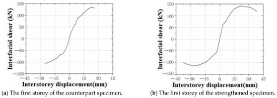
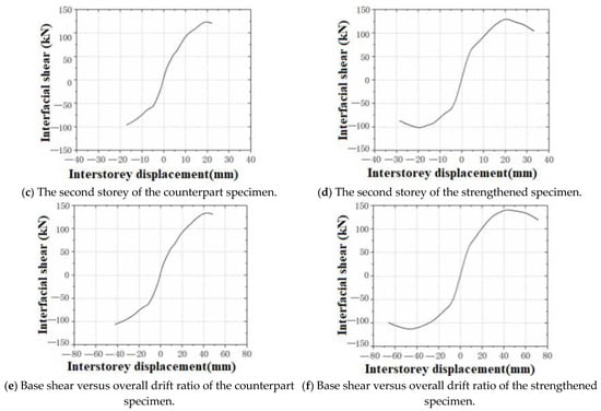
Figure 8.
Backbone curves of specimens.
3.3. Stiffness
For structural design in engineering applications, the equivalent stiffness is frequently used to evaluate the integral stiffness of frames at different loading stages. Some featured points, including cracking point, yield point, peak point and ultimate point, can be identified in backbone curves, as shown in Figure 9. The cracking point (Point A) represents the first crack appearing in the specimen, where Pcr and Δcr represent the cracking load and drift ratio, respectively. The yield point (Point B) can be obtained using the energy equivalent method (i.e., SOAF = SCDF), where Py and Δy represent the yield load and drift ratio, respectively. The peak point (Point D) refers to the maximum load, Pm and its drift ratio, Δm. The ultimate point (Point E) is equal to Pu (i.e., 0.85Pm), where Pu and Δu represent the ultimate load and drift ratio, respectively. The equivalent stiffness is defined as the ratio between positive load (or negative load) and its corresponding positive displacement (or negative displacement) at featured points. Table 3 lists the equivalent stiffness of the two specimens at different loading stages.
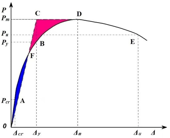
Figure 9.
Diagram of the energy equivalent method.
Table 3.
Equivalent stiffness at featured points.
For these two specimens, stiffness reduced as drift increased. Both declined rapidly before the yield stage, with the concrete cracking and crushing. The degradation of stiffness was slow due to the ductility of the steel bars. Overall, the cracking stiffness of the strengthened specimen was significantly larger than that of the counterpart specimen, with an average increase of 11%. However, the effects of improvement at the inelastic stage (i.e., yield stiffness, peak stiffness and ultimate stiffness) were quite small—up to a 5% increase in stiffness. This indicates that the CFRP wrapping made more contributions to enhancing the frame stiffness at the elastic stage.
3.4. Ductility
Ductility can reflect the deformation capacity of frames and is expressed as follows:
where is the ductility coefficient, is the ultimate displacement and is the yield displacement. Table 4 lists the ductility coefficient of the strengthened specimen. The ductility of the counterpart specimen was very limited, given that the lateral loading capacity reduced sharply during the failure stage. The ductility of the strengthened specimen can be assessed using the regression formula [34]:
where is the stirrup characteristic value, is the shear span ratio, is the column-to-beam flexural strength ratio and n is the axial compression ratio. These parameters can be obtained based on the equations below.
Table 4.
Displacement ductility coefficient.
The stirrup characteristic value is given as follows:
where n1 and n2 are the numbers of column sections given in two directions, As1 and As2 are the areas of stirrups, l1 and l2 are the lengths of column sections, is the yield strength of stirrups, is the compressive stress of concrete, Acor is the core area of the concrete and s is the distance between two stirrups.
The shear span ratio is given as follows:
where Hn is the column height and h0 is the effective height of the column section.
The column-to-beam flexural strength ratio is given as follows:
where ΣMuc is the sum of ultimate moments at column ends in node regions and ΣMub is the sum of ultimate moments at beam ends in node regions.
The axial compression ratio is given as follows:
where N is the axial force, fck is the axial compressive strength of the concrete and A is the overall area of the concrete.
Based on Equation (2), the lower limit value of the displacement ductility coefficient for these specimens is 2.57. The ductility coefficients of strengthened and counterpart specimens were 3.41 and 3.00, respectively. This indicates that the CFRP wrapping can significantly improve the ductility of frames.
3.5. Energy Dissipation
The energy dissipation capacity is an important index for evaluating the seismic performance of the frame. In the pseudo-static test, the cumulative energy dissipation is the accumulated sum of the area of the hysteretic curve envelope of the loading cycle, as shown in Figure 10. The energy dissipation capacity of the strengthened specimen was generally larger than that of the counterpart specimen. This may be attributed to the fact that the CFRP sheets have a restraining effect on the deformation of the specimen. The friction energy dissipation increased the total structural energy dissipation, particularly in the plastic hinge area in the inelastic stage.
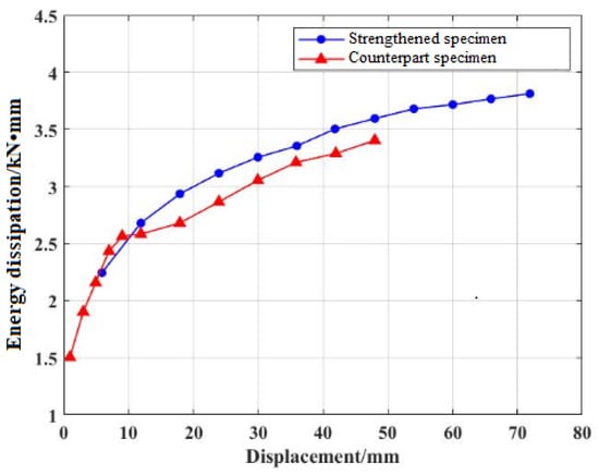
Figure 10.
Energy dissipation capacity.
4. Modelling in OpenSees
4.1. Frame Model
The experimental frame was modeled using the macro-modeling strategy, namely the Open System for Earthquake Engineering Simulation (OpenSees). All the study frames were modeled using the material and geometrical values available in the test. The uniaxial material called Concrete02 was used and the tensile strength of concrete was considered. The compressive strength of concrete was set to 35 MPa and the tensile strength was set to 10% of the compressive strength. The nonlinear monotonic behaviors of concrete beams and column elements were determined using a multi-linear curve. To simulate the pinching behavior and stiffness degradation of material under cyclic loading, the pinching4 material was used in beam and column elements, as shown in Figure 11. Beam and column sections were modeled using fiber sections, which can accurately predict the inelastic behavior of concrete.
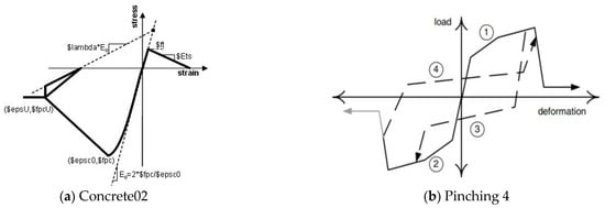
Figure 11.
Material parameters in used in the models.
4.2. Model Validation
Figure 12 compares the measured shear response of these two specimens with the computed response from the numerical model. The hysteresis curves obtained from the test and the numerical simulation matched. The degradation of both stiffness and lateral loading capacity was considered in the numerical simulation. The backbone curve obtained from the numerical analysis provides an accurate estimate of the maximum drift capacity of frames. The sharp degradation in stiffness and brittle failure in the final stage was captured in the numerical analysis.
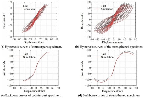
Figure 12.
Comparison of test and OpenSees model.
4.3. Pushover Analysis
The capacity spectrum method (CSM) is an efficient and reliable seismic analysis tool for structural vulnerability studies. Thus, this study applied the capacity spectrum method to evaluate the improvement of the strengthened method on the seismic capacity of damaged frames. The prototype of the five-storey, two-span RC frame mentioned above was evaluated, as shown in Figure 13. The strengthened scheme is the same as the scaled model but has a length of 600 mm. The lateral load followed the inverted triangle distribution.
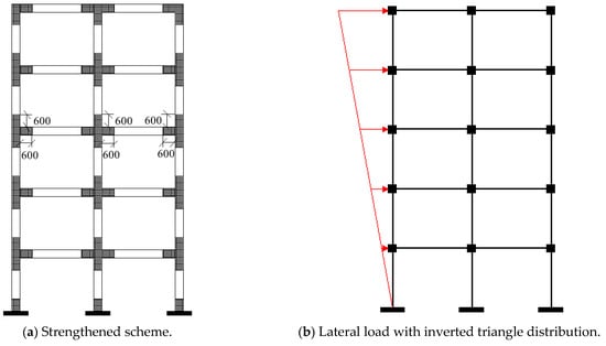
Figure 13.
Strengthened scheme and lateral load.
Figure 14 shows the location of plastic hinges developed in both the yield stage and the ultimate stage. The sequences of plastic hinges are marked with numbers. The lateral load increased steadily beyond its elastic limit, and the first plastic hinge appeared at the end of the first-storey beam; this decreased the overall stiffness of the structure and promoted the development of plastic hinges, as shown in Figure 13a. More plastic hinges were formed as the base shear increased monotonically, continuously expanding to the column section. Finally, the plastic hinges moved to the ultimate stage with the failure of the column and fifth-storey beam, as shown in Figure 13b. The failure of the strengthened frame was a typical beam hinge mechanism, which proved the efficiency of the CFRP wrapping scheme.
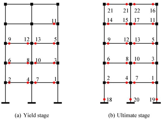
Figure 14.
Hinge stage developed in the frame.
Using the pushover analysis, the nonlinear response of frame structures can be identified using the base shear versus overall drift response, as shown in Figure 15a. The capacity spectrum is represented in the Acceleration Displacement Response Spectrum (ADRS) format using spectral displacement (Sd = Sa/ω2) and spectral acceleration (Sa). Specifically, the base shear, Vb, versus overall drift response, Δroof, can be transformed into spectral displacement, Sd, versus spectral acceleration, Sa, using the following expressions:
where Mk, Pk and Φk are modal mass, mode participation factor and modal amplitude at the rooftop for the first mode (k = 1). M and W are the total mass and the weight of the building. The spectral displacement versus spectral acceleration can be obtained as shown in Figure 15b.
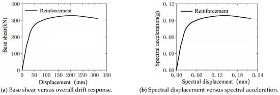
Figure 15.
Response spectrum in ADRS.
In the Code for Seismic Design of Buildings in China, three-level performance objectives of buildings in seismic-prone regions should be evaluated further, including frequent earthquakes (minor earthquakes), basic earthquakes (moderate earthquakes) and rare earthquakes (severe earthquakes). With the application of the CSM, the capacity spectrum and the response spectrum intersect (Point A, Point B and Point C shown in Figure 16). Different balance points corresponding to three levels of earthquakes were identified. The intersection point is defined as the locus of the performance point. Table 5 lists the results obtained at performance points in three levels of earthquakes. Based on the performance point, the overall performance of the structure can be evaluated to identify whether the strengthened frame can realize the required performance level specified in the seismic design code. In the future, artificial intelligence technologies such as shape-based distance (SBD)-K-medoids [35] can be used to analyze and optimize the CFRP strengthening scheme. The systematic method can offer a new approach for efficiently identifying the best CFRP strengthening scheme.
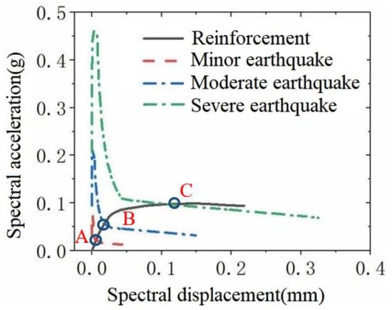
Figure 16.
Capacity spectrum method applied to the strengthened specimen.
Table 5.
Results at the performance point.
To evaluate the efficiency of the CFRP wrapping scheme, the interstorey drift ratio during a severe earthquake was plotted as shown in Figure 17. The distribution of the interstorey drift ratio as the height increased was non-uniform; in particular, the interstorey drift ratio was higher at lower heights of the structures. The largest interstorey drift ratio (0.013) occurred on the first floor; this ratio is below the limit of seismic specification (i.e., 1/50 in severe earthquakes).
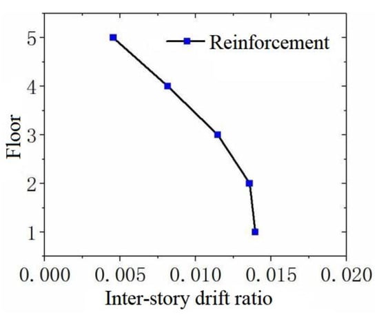
Figure 17.
Interstorey drift ratio in a severe earthquake.
5. Conclusions
This paper presented results from experimental and numerical studies conducted to evaluate the seismic performance of a strengthened RC frame and its counterpart. The behaviors of two large-scale RC specimens were experimentally investigated by applying axial compression force and lateral cyclic loading. The seismic performance, including cyclic lateral load-drift responses, lateral load capacity and stiffness, displacement ductility ratios and energy dissipation capacity were obtained. The inelastic OpenSees model was developed further and benchmarked using the experimental results. The following conclusions are based on the experimental and numerical results summarized in this study.
- CFRP reinforcement can efficiently improve the lateral bearing capacity and initial stiffness of earthquake-damaged RC frame structures, especially the obvious improvement in ductility and energy dissipation capacity. The strengthened specimen shows excellent ductility without an obvious pinching phenomenon in plump hysteretic load-displacement curves.
- Based on pushover analysis using the capacity spectrum method, the failure of the strengthened prototype frame is a typical beam hinge mechanism rather than the column hinge mechanism or composite hinge mechanism. CFRP strengthening can relocate the plastic hinge and help achieve specific seismic performance goals.
- Even in severe earthquakes, the strengthened prototype frame can maintain structural integrity and safety, with its maximum interstorey displacement angle below the limit of seismic specification (i.e., 1/50 in severe earthquakes).
Although the effectiveness of CFRP strengthening techniques has been demonstrated in this paper, some significant parameters such as the effect of floor slab and beams and columns in three-dimensional (3D) structures were not considered in the current study. The CFRP strengthening technique applied in planar structures provides the basis for future studies of 3D structures.
Author Contributions
Y.W.: methodology, writing—review and editing; W.C.: conceptualization, funding acquisition, correspondence; D.L.: experiment, writing—original draft; H.X.: investigation, writing—review and editing; F.Z.: methodology, writing—review and editing; X.G.: drawing, editing. All authors have read and agreed to the published version of the manuscript.
Funding
This study was financially supported by the Science and Technology Research and Development Project of CSCEC (Grant No. CSCEC-2021-Z-24).
Data Availability Statement
The data presented in this study are available on request from the authors.
Conflicts of Interest
The authors declare no conflict of interest.
References
- Wang, L.K.; Zhou, Y.; Nagarajaiah, S.; Shi, W.X. Bi-directional semi-active tuned mass damper for torsional asymmetric structural seismic response control. Eng. Struct. 2023, 294, 116744. [Google Scholar] [CrossRef]
- Liu, Y.; Fan, L.; Wang, W.; Gao, Y.; He, J. Failure analysis of damaged high-strength bolts under seismic action based on finite element method. Buildings 2023, 13, 776. [Google Scholar] [CrossRef]
- Chen, Z.; Yu, J.M.; Nong, Y.M.; Zhang, H.X.; Tang, Y.C. Beyond time: Enhancing corrosion resistance of geopolymer concrete and BFRP bars in seawater. Compos. Struct. 2023, 322, 117439. [Google Scholar] [CrossRef]
- Lee, M.; Wang, W.; Wang, Y.; Hsieh, Y.; Lin, Y. Mechanical properties of high-strength pervious concrete with steel fiber or glass fiber. Buildings 2022, 12, 620. [Google Scholar] [CrossRef]
- Wang, L.K.; Zhou, Y.; Shi, W.X.; Zhou, Y. Seismic response control of a nonlinear tall building under mainshock-aftershock sequences using semi-active turned mass damper. Int. J. Struct. Stab. Dyn. 2023. [Google Scholar] [CrossRef]
- Federal Emergency Management Agency (FEMA). NEHRP Guidelines for the Seismic Rehabilitation of Buildings. FEMA Report 273; Building Seismic Safety Council: Washington, DC, USA, 1997.
- Katsumat, H.; Kobatake, Y.; Taked, T. A study on the strengthening with carbon fiber for earthquake-resistant capacity of existing reinforce concrete columns. In Proceedings of the 9th World Conference on Earthquake Engineering, Tokyo-Kyoto, Japan, 2–9 August 1988; pp. 518–522. [Google Scholar]
- Saadatmanesh, H.; Ehsani, M.R.; Jin, L. Seismic retrofitting of rectangular bridge columns with composite straps. Earthq. Spectra 1997, 13, 281–304. [Google Scholar] [CrossRef]
- Ye, L.P.; Zhang, K.; Zhao, S.H.; Feng, P. Experimental study on seismic strengthening of RC columns with wrapped CFRP sheets. Constr. Build. Mater. 2003, 17, 499–506. [Google Scholar] [CrossRef]
- Richelle, G.A.; Kawashima, K. Analysis of carbon fiber sheet-retrofitted RC bridge columns under lateral cyclic loading. J. Earthq. Eng. 2009, 13, 129–154. [Google Scholar]
- Ghobarah, A.; Said, A. Shear strengthening of beam-column joints. Eng. Struct. 2002, 24, 881–888. [Google Scholar] [CrossRef]
- Wang, L.K.; Nagarajaiah, S.; Zhou, Y.; Shi, W.X. Experimental study on adaptive-passive tunned mass damper with variable stiffness for vertical human-induced vibration control. Eng. Struct. 2023, 280, 115714. [Google Scholar] [CrossRef]
- Wang, L.K.; Nagarajaiah, S.; Shi, W.X.; Zhou, Y. Seismic performance improvement of base-isolated structures using a semi-active tuned mass damper. Eng. Struct. 2022, 271, 114963. [Google Scholar] [CrossRef]
- Antonopoulos, C.P.; Triantafillou, T.C. Experimental investigation of FRP-strengthened RC beam-column joints. J. Compos. Constr. 2003, 7, 39–49. [Google Scholar] [CrossRef]
- Duong, K.V.; Sheikh, S.A.; Vecchio, F.J. Seismic behavior of shear-critical reinforced concrete frame: Experimental investigation. ACI Struct. J. 2007, 104, 304–313. [Google Scholar]
- El-Sokkary, H.; Galal, K. Analytical investigation of the seismic performance of RC frames rehabilitated using different rehabilitation techniques. Eng. Struct. 2009, 31, 1955–1966. [Google Scholar] [CrossRef]
- Shaikh, Z.K.; Sohoni, V.S. Performance of carbon fiber-reinforced polymer (CFRP)-strengthened RC frame. Asian J. Civ. Eng. 2023, 24, 1831–1840. [Google Scholar] [CrossRef]
- Ali, O.; Bigaud, D.; Riahi, H. Seismic performance of reinforced concrete frame structures strengthened with FRP laminates using a reliability-based advanced approach. Compos. Part B- Eng. 2018, 139, 238–248. [Google Scholar] [CrossRef]
- Rousakis, T.C.; Saridaki, M.E.; Mavrothalassitou, S.A.; Hui, D. Utilization of hybrid approach towards advanced database of concrete beams strengthened in shear with FRPs. Compos. Part B-Eng. 2015, 85, 315–335. [Google Scholar] [CrossRef]
- Rousakis, T.C.; Anagnostou, E.; Fanaradelli, T.D. Advanced composite retrofit of RC columns and frames with prior damages-Pseudodynamic finite element analyses and design approaches. Fibers 2021, 9, 56. [Google Scholar] [CrossRef]
- Fanaradelli, T.D.; Rousakis, T.C.; Karabinis, A. Reinforced concrete columns of square and rectangular section, confined with FRP-Prediction of stress and strain at failure. Compos. Part B-Eng. 2019, 174, 107046. [Google Scholar] [CrossRef]
- Fanaradelli, T.D.; Rousakis, T.C. 3D finite element pseudo dynamic analysis of deficient rectangular columns confined with fiber reinforced polymers under axial compression. Polymers 2020, 12, 2546. [Google Scholar] [CrossRef]
- Fanaradelli, T.D.; Rousakis, T.C. Prediction of ultimate strain for rectangular reinforced concrete columns confined with fiber reinforced polymers under cyclic axial compression. Polymers 2020, 12, 2691. [Google Scholar] [CrossRef] [PubMed]
- Anagnostou, E.; Rousakis, T.C. Performance of steel bar lap splices at the base of seismic resistant reinforced concrete columns retrofitted with FRPs-3D finite element analysis. Fibers 2022, 10, 107. [Google Scholar] [CrossRef]
- Garcia, R.; Hajirasouliha, I.; Pilakoutas, K. Seismic behaviour of deficient RC frames strengthened with CFRP composites. Eng. Struct. 2010, 32, 3075–3085. [Google Scholar] [CrossRef]
- Wattanapanich, C.; Imjai, T.; Garcia, R.; Rahim, N.L.; Abdullah, M.M.A.B.; Sandu, A.V.; Vizureanu, P.; Matasaru, P.D.; Thomas, B.S. Computer simulations of end-tapering anchorages of EBR FRP-strengthened prestressed concrete slabs at service conditions. Materials 2023, 16, 851. [Google Scholar] [CrossRef] [PubMed]
- Muslum, M.M.; Fatih, K. Structural Performance of reinforced concrete (RC) moment frame connections strengthened using FRP composite jackets. Arab. J. Sci. Eng. 2021, 46, 10975–10992. [Google Scholar]
- Attari, N.; Youcef, Y.S.; Amziane, S. Seismic performance of reinforced concrete beam–column joint strengthening by FRP sheets. Structures 2019, 20, 353–364. [Google Scholar] [CrossRef]
- Imjai, T.; Garcia, R.; Guadagnini, M.; Pilakoutas, K. Strength degradation in curved fiber-reinforced polymer (FRP) bars used as concrete reinforcement. Polymers 2020, 12, 1653. [Google Scholar] [CrossRef]
- Hanan, A.N.; Muneer, N. Confinement effects of unidirectional CFRP sheets on axial and bending capacities of square RC columns. Eng. Struct. 2019, 196, 109329. [Google Scholar]
- Imjai, T.; Guadagnini, M.; Pilakoutas, K. Curved FRP as concrete reinforcement. Proc. Inst. Civ. En.-Eng. 2009, 162, 171–178. [Google Scholar] [CrossRef]
- Yang, J.; Liang, S.T.; Zhu, X.J.; Dang, L.J.; Wang, J.L.; Tao, J.X. Experimental research and finite element analysis on the seismic behavior of CFRP-strengthened severely seismic-damaged RC columns. Structures 2021, 34, 3968–3981. [Google Scholar] [CrossRef]
- Applied Technology Council (ATC). Guidelines for Cyclic Seismic Testing of Components of Steel Structures; ATC-24; ATC: Redwood, CA, USA, 1992. [Google Scholar]
- Guan, H.B.; Wang, Q.X. Experimental investigation of seismic performance of concrete-filled glass fiber reinforced polymer tubular columns. J. Harbin Inst. Technol. 2011, 18, 37–43. [Google Scholar]
- Shen, Y.M.; Zhang, D.M.; Wang, R.L.; Li, J.P.; Huang, Z.K. SBD-K-medoids- based long-term settlement analysis of shield tunnel. Transp. Geotech. 2023, 42, 101053. [Google Scholar] [CrossRef]
Disclaimer/Publisher’s Note: The statements, opinions and data contained in all publications are solely those of the individual author(s) and contributor(s) and not of MDPI and/or the editor(s). MDPI and/or the editor(s) disclaim responsibility for any injury to people or property resulting from any ideas, methods, instructions or products referred to in the content. |
© 2023 by the authors. Licensee MDPI, Basel, Switzerland. This article is an open access article distributed under the terms and conditions of the Creative Commons Attribution (CC BY) license (https://creativecommons.org/licenses/by/4.0/).