Abstract
The article addresses the problem of safety evaluation of steel moment frames of civil buildings, e.g., warehouses, shops, garages, and multistory industrial buildings on deformable soil in the relevant case of an emergency impact. The case of accidental emergency impacts is considered when such parameters as the point, direction, and intensity of an impact cannot be predetermined. Such impacts are not expected to trigger the progressive collapse of currently implemented design solutions and the whole structure must maintain the property of survivability. To evaluate this property, several calculations are to be made in the quasi-static statement to identify the stress–strain state under the most dangerous accidental impacts. Further, final calculations are to be made in the dynamic statement. In this case, the problem of search is solved using the criterion of minimizing the integral safety margin of structural elements in a steel moment frame design. Calculations prevent the frame stability loss. The calculation is performed in the quasi-static statement using models made in compliance with the deformation theory of plasticity, while the calculation in the dynamic statement takes into account the associated plastic flow rule. The proposed procedures allow for designing steel moment frames that are resistant to accidental emergency impacts. Impact loading is analysed as pulse loading, which is statically equivalent to the dynamic effect of an inelastic impact of a stiff body on a structural system. The design and the efficiency evaluation of a steel moment frame of a two-story building are considered.
1. Introduction
1.1. Review of Works Focused on the Research Problem
Today the analysis and design of steel moment frames of buildings, subjected to impact loading, is a relevant issue that arouses the interest of numerous researchers. Let us take a closer look at the following aspects addressed in a variety of works on this issue.
1.1.1. Type of Loading
Several authors have studied steel moment frames subjected to lateral impacts. Indeed, the authors of work [1] emphasize that lateral dynamic loading has a most dangerous effect on the steel structures of buildings. Lateral dynamic loading can be triggered both by the ground motion and lateral impacts. The design of semirigid joints, which can effectively contribute to energy dissipation, is one of the effective measures in this case. Varying the stiffness of columns and beams is another approach that makes the structure optimal in terms of resistance to such effects. Work [2] shows that versatile dynamic effects can be reduced to equivalent effects that are applicable in calculations and experimental studies. The importance of axial and lateral impact testing is emphasized. Article [3] addresses the lateral impact loading of tubular frames. Here, the authors consider quasi-static and dynamic approaches and obtain divergent results. While the element, subjected to impact loading, may collapse under the quasi-static approach, the adjacent element may lose stability under the dynamic approach. That is why the two approaches are also applied in this article.
Studies focused on the impact of a free-falling body are of interest. For example, in [4], the progressive collapse of steel moment frames, subjected to the impact load from a pile hammer, was investigated. It was found that the collapse scheme was accompanied by the formation of plastic hinges. However, the type of joint and its stiffness have a strong effect on the formation of catenary action that mitigates progressive collapse. The authors of [5] focus on the impact triggered by falling fragments of structures. A steel frame supporting a concrete slab is analysed. Strength-limit values and the catenary scheme of resistance to bending are identified for such structures. The authors argue that the strength of structures can rise if the rates of deformations are high. Joints of steel moment frames, subjected to the impact of a dropped object, are studied in [6]. The authors show that hinge joints with symmetrical friction dampers demonstrate the best resistance to seismic loads. They are also effective in cases of impacts from dropped objects. The authors use the term “sustainable design of structures”. It refers to the ability of a structure to withstand emergency accidents with minimal damage. The same concept is applied in this article. Work [7] focuses on the types of impact from a dropped object. It is found that, at low velocities, the impact of a body falling on a steel frame is close to a rigid impact. At the high velocities of a dropped body, the impact is fully plastic. These features have a major effect on the frame’s resistance to progressive collapse.
Many researchers study the impact of a steel car frame on columns. The author of article [8] analyses collisions of a light or heavy vehicle with the edge columns of steel frames whose design takes account of seismic loading. The input data, designated for analyses of impact effects, are employed to track the history of structure loading and evaluate the probability of the building frame collapse in case of an impact on a car. The effect of this impact [9], causing a progressive collapse of the building steel frame, was evaluated using the following methods: selection of impact parameters, use of the impact equation when a nonlinear dynamic analysis was made without column removal, and analysis of the impact that triggered the column removal. The latter approach is the most realistic and problematic one for the structure in terms of deformations and the number of plastic hinges. The authors of [10] consider the optimization of structures under such loadings. The resistance of structures to emergency impacts serves as the optimality criterion. Genetic algorithms, PSO, and other methods are considered as solutions to this problem.
Blast and seismic effects are dynamic in nature, similar to single and recurring ones. Some researchers consider blast loading as one of the dangerous types of effects on steel moment frames. In [11], the pulse, having a triangular shape, is used to simulate a blast. It is shown that the strength of steel rises due to the high rate of deformations. The thickness of elements, used to make flanged joints, can be increased to raise resistance to blast effects. The blast-spot position is fixed [12] and the effect on the frame is reduced to the pulse action, taking into account the distance over which the shock-wave front propagates. When analyzing the effect of dynamic, including seismic, loads on a structure [13], the problem of finding the restoring force can be solved. The solution can be used to identify the effect in the case of substantial plastic deformations of a structure.
1.1.2. Stress–Strain State of Joints and Elements
These studies are focused on the mechanical characteristics of materials, plastic deformation, and energy dissipation. In [14], modal analysis is used to identify the mechanical characteristics of structures in operation for a certain period of time, namely, structures of historic buildings. This approach can be applied to identify the boundary conditions of structures, including those boundary conditions that are triggered by accidental impacts. The authors of [15] mention that, in case of impacts, the mechanical characteristics of a material, e.g., yield strength and geometrical features of a structure, can be taken into account as random values using the Monte Carlo method. The type of cross-section of a steel element is important for its ability to absorb the impact energy. According to [16], when impact effects are considered, the important aspects are the impact strength and the structure’s ability to absorb energy. This article considers structures having different joints in thin-walled metal cross-sections of beams and columns. Spots of the impact-load application, located in the middle of the span and near the support, are considered. It is assumed that, according to the first scheme, collapse is triggered by tension–compression and bending; while according to the second one, collapse is triggered by shear. Similar spots of accidental impacts will be considered in this article. The authors of [17] studied bolted beam–column connections on flanges, in the case when welding holes had different shapes. It is shown that connections, allowing the frame to pass into the state of catenary deformation, are preferable. In [18], the plastic deformation of I-beam section columns, subjected to a combination of effects, is considered. It is shown in an experiment that the flexibility of elements is an important factor of static loading triggered by bending and compression, which is taken into account by the quasi-static approach implemented in this paper.
1.1.3. Taking Account of Soil–Structure Interaction
Work [19] considers an integrated approach to seismic effects on steel moment frames, taking into account soil–structure interaction. It is emphasized that soil-base subsidence and structural failure are the most important factors in the analysis of dynamic effects on buildings and structures. Some works focus on the numerical modelling of soil bases. Such models are an important factor in the stress–strain state analysis of steel moment frames. Soil bases can be modelled using both nonlinear elements of the Link type and elastic elements of the Spring type [20]. Some modelling approaches use GAP elements or alternative options [21,22].
1.1.4. Studying the Process of Progressive Collapse
The authors of [23] analyse the resistance to progressive collapse in the case when columns are removed by impact loading. In the course of making a comparison with traditional column modelling, the authors argue that if the impact is not taken into account in the case of column removal, stress distribution in the joints of structural elements can be unrealistic and the adequate collapse mode can be underestimated. In this case, much depends on energy absorption by the structure and the impact velocity. Article [24] deals with integrated effects that include impacts. The authors argue that the greatest resistance to progressive collapse arises in square-section columns. The process of progressive collapse is described in more detail in [25], where the authors prove that the dynamic ratio of frames is less than 2.0, as accepted in some cases, and an impact can trigger a collapse in the case of the loss of strength of beam–column joints or the failure of columns due to the loss of its strength or stability. In [26], the reliability of the steel-frame design is studied to prevent various scenarios of progressive collapse based on brittleness curves. In this case, the impact force is set using the Monte Carlo method, and the response to this loading is identified using the response surface or an artificial neural network. As a result, the probability of failure of a steel moment frame, subjected to a particular impact, is calculated.
In the articles [27,28], the resistance of steel frames to progressive collapse is achieved by the design of nodal joints, as shown in Figure 1a, in which the plastic deformation zone expands and extends outside the boundaries of the joint, which is called “out-shift plastic zone” by the authors [27]. In [28], the design of the node increases its resistance to progressive collapse at large rotation angles. All this increases the resistance of steel frames in general to the effects associated with column removal.
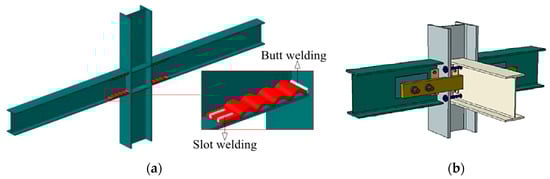
Figure 1.
The structural design of beam–column joints: reported in [27] (a) and in [28] (b).
Another effective way to distribute forces during column removal is the use of infilled frames [29]. In Figure 2a, such frames are compared with conventional frames, the authors establish that the design solution increases the resistance of the system to gradual progressive collapse.
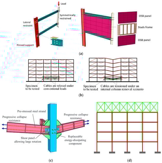
Figure 2.
Structural designs for protection against progressive collapse: infilled frames [29] (a), relaxed-tensioned cables (b) [30], prestressed joint with energy dissipating elements (c) [31], and supplementary frame structure (d) [32].
The structural design proposed in [30], in Figure 2b, which can increase the safety of building frame systems both under seismic effects and in case of emergency column removal, is the use of cables without prestressing, which begin to resist the load when large deflections are obtained; the effectiveness of such a system is proven experimentally and theoretically.
In [31], in Figure 2c, the nodal connection is modified based on two principles. The first one is energy absorption by the replaced elements. The second is prestressing by the strands to resist progressive failure while allowing rotations in the node. The effect of resistance to progressive collapse can be achieved by providing an additional roof frame for both the planned and existing buildings. The column removal loads are transferred to this frame through vertical cables and it effectively dissipates the deformation energy [32] Figure 2d. Other aspects related to the protection of frame structures against progressive collapse are reported in [33].
1.1.5. The Effect of Initial and Impact-Triggered Imperfections
An important factor, affecting the bearing capacity of steel-structure elements is their resistance to local compression [34]; this effect can be manifested in the case of geometry-related imperfections and inaccurate installation and it can affect the bearing capacity under dynamic loading. Such imperfections mostly affect the stability of elements in bending and compression, which is proven in [35]. The author also argues that it is necessary to study the deformation state of structures after the loss of stability. Another article [36] addresses an experimental study of tubular frames consisting of two parallel belts connected by a triangular lattice that resists the impact, having the same energy characteristic, but different spots of loading application. The first one is in the middle of the truss panel and the second is at the intersection of the belt and the lattice. The local loss of strength affects the behaviour of the structure as a whole. Imperfections have a strong impact on the behaviour of steel structures subjected to impact loading, which leads to tighter manufacturing and installation requirements in contrast to, for example, reinforced concrete structures [37].
1.1.6. Other Features
In addition to the evaluation of the framework’s resistance to emergency effects, the most important issue is its environmental impact. This aspect was taken as a benchmark when a steel moment frame was selected for the case study. The main provisions of [38] stand for this decision. Of some interest is the lifecycle of a structure, taking into account the impact perception to be evaluated using the methodology provided in [39], based on the variant design of a steel structure and the restorability of its bearing capacity.
1.2. Purpose and Objectives of the Research Addressed in This Article
The purpose of the research addressed in this article is to ensure the mechanical safety of steel moment frames subjected to emergency impacts having uncertain parameters, such as the spot of application, direction, and intensity of impact loading. Several tasks are solved to achieve this preset purpose.
- An integral efficiency factor is introduced for safety evaluation purposes (Section 2.2.1). The calculation of the efficiency factor takes into account the random nature of impacts. These impacts are modelled using the approach described in Section 2.1.2, while the effects of an impact on a steel structure are evaluated using the survivability criteria described in Section 2.1.3;
- To calculate the components of the stress–strain state and the stability of a structure at the initial stage, it is proposed to use a quasi-static approach based on the methodology described in Section 2.2.1, with subsequent verification of the result using the dynamic calculation (Section 2.2.2) method. In this case, a multilayered finite element (Section 2.2.3) is constructed to analyse the deformations of steel profiles, which allows for modelling the formation of plastic hinges using a rigid plastic model of the material. The model takes into account the force transfer from the steel moment frame to the deformable soil base, whose part can be removed as a result of an accidental impact (Section 2.2.4);
- The results of the proposed approach are verified experimentally (Section 3.1). A practical case of analysis of a steel moment frame, subjected to impact loading (Section 3.2), is provided and the efficiency of the design solution is evaluated using the integral efficiency factor described in Section 2.2.1.
The novelty of the research lies in the approach to evaluating the mechanical safety of steel moment frames of buildings, taking into account the accidental occurrence of the most dangerous combinations of impacts in the form of a concentrated plastic impact. An algorithm for shock generation and a formula for assessing the mechanical safety of the system based on the value of the integral safety margin are generated.
2. Materials and Methods
2.1. Statement of the Research Problem
2.1.1. General Provisions
Steel moment frames modelled using spatial rods subjected to deformations due to tension–compression, bending, and flexure are considered. Joints of rods are assumed to be rigid. The strength of welded joints is assumed to be sufficient; parameters of welded joints are not considered. The frame structure of a building passes loads to the soil base through reinforced concrete-column foundations. The soil-base model is a linearly deformable Winkler half space. In the general case, rod elements can have both open and closed thin-walled cross-sections. In this case, the warping restraint of cross-sections under emergency impact loads, that are close to the limit ones, is not taken into account. The strength, stiffness, and stability limits of structures, as well as the soil-base stiffness limits, are taken into account in the case of the normal operation of structures. It is assumed that the floor beams of buildings are a single rigid body and no local collapse is triggered as a consequence of impacts.
The mechanical safety and efficiency of a design solution are evaluated for each case of loading using the value of the integral safety margin based on equivalent stresses for the structure as a whole. Towards this end, the search optimization problem is solved as follows:
where is the number of cross-sections of structural elements considered in the process of evaluating ; is the ultimate resistance of structural steel; is the von Mises stress in the considered cross-section. The random search method (its Monte Carlo type), coupled with the storage of optimized solutions, is used as a solution search tool. The author’s algorithm, verified by the experiment and the NX Nastran solver, is used as a tool for analyzing the stress–strain state of steel moment frames subjected to impact loading.
2.1.2. Accidental Impact Generation Procedure
Special operating conditions of a steel moment frame do not contemplate any deterministic spot of impact application, its direction, or intensity. An array of source data and the results of analyses are formed to take into account these operating conditions in the course of design.
Let us present an accidental impact as pulse , acting on a structure during time ; then, the equivalent of the mechanical dynamic force will be equal to . Within the framework of quasi-static analysis, conventional static impact loading can be considered as the one that is unexpectedly applied to the structure. Further, using a well-known formula to evaluate the effect of impact, we can assume that . Hence, to reduce the laboriousness of the computations associated with the detailed dynamic analysis, we can proceed from pulse loading to its quasi-static equivalent. Taking into account Newtonian formalism, the value of this load will be as follows:
where it is the mass of a rigid body making an impact at a finite velocity .
Hence, for simplification purposes, pulse effect modelling can be reduced to static modelling. It is noteworthy that in our case such a technique does not replace the dynamic analysis; rather, it is a tool for a faster search of the most dangerous spot of impact application.
Therefore, the generation of impact loading will have a number of steps:
- Generation of arrays of values for vector omponents in the form , ; is the number of potential component values to select from. Here we calculate vector components as ;
- Generation of data array describing the structural elements of a steel moment frame:
here, is the number of the group of structural elements; nominally, there can be one group of “rods” or several groups, such as “beams”, “columns”, etc.; is the number of groups of elements within one structural element; is the number of finite elements in group ; is the number of the first finite element in group ; is the total number of structural elements. Obviously, for this data structure, the numbering of finite elements within one structural element should be ascending. In addition, the number of elements in a group must be a multiple of six;
- 3.
- Random selection of a structural element from structure ;
- 4.
- Random selection of the third, fourth, or fifth joint from the group of elements listed in the ascending order, starting from ;
- 5.
- The loading of the joint, selected at step 4, using loading values that are randomly selected from the interval at step 1.
2.1.3. Criterial Assessment of Resistance to Progressive Collapse and Survivability of the Structure
In an emergency situation, in particular, under impact loading, the structure resists progressive collapse. If this resistance leads to the halt of progressive collapse, that is, to its localization in some part of a bearing system, then the structure is considered to have survivability. In this case, the time during which no further expansion of localization of destruction occurs should be sufficient for the safe evacuation of people and equipment. At present, a survivability criterion was proposed in [40] for reinforced concrete structures with unexpectedly removed supports; it is based on the evaluation of parameter , in which values of loads are the ultimate values for this accident and that correspond to its operating conditions before the accident. The value of is found using the limit equilibrium theorem. Hence, it is the minimum load value at which the system does not convert into a geometrically changeable one (a mechanism).
The following conditions are proposed as survivability criteria for structural systems of buildings subjected to impacts:
- Prevention of any large changes in the geometry of a structural system, taking into account its possible plastic deformation or loss of stability. This condition can be formulated as follows:
In accordance with the above interpretation of survivability of a building, the following logical operations are proposed [41]:
where is the span of a damaged structure; is the floor height; and is the coefficient depending on the value of this height. For standard floor heights exceeding three meters , for the heights of 2.5–3 m , for engineering floors (if necessary) , and for the limitations on horizontal displacements in case of horizontal impacts. In this case, we do not consider high-rise buildings, so there is no separate limitation on horizontal displacements;
- 2.
- For the condition of the absence of cracks as a result of local ruptures of elements, which can be formulated for any (most heavily loaded) cross-section of an element, let n, the most stressed characteristic points of a cross-section, be considered; then,
2.2. Method of Dynamic Analysis of Steel Moment Frames Subjected to Impact Loading
2.2.1. Iterative Pattern for Preliminary Strength and Stiffness Evaluation
In the first iteration, linear analysis is performed for each impact loading and the following system of linear equations is solved in subsequent iterations:
where is the tangent stiffness matrix of a spatial finite-element model; is the vector of nodal displacements calculated in iteration r; is the vector of nodal forces that takes into account the standard effect; and is the vector of the self-balanced system of small nodal forces, that can take nonzero values for any nodal degree of freedom (to solve the initial stability problem using FEM).
The tangent stiffness matrix can be formulated as follows:
where is the stiffness matrix of the finite-element model, is the geometric matrix of the finite-element system, expressed through longitudinal forces in the rods found in iteration , and combined into vector .
Let us introduce the stability-assurance condition, stemming from the assumption that the lack of convergence of solutions means the loss of stability. The stability-loss condition is controlled by verifying the following condition for a preset iteration number
where and are the facility’s deformation energies obtained in iterations and , respectively; is a preset small positive number.
As the calculations show, the verification procedure of this type is sufficiently effective at , . There is no need to recalculate the tangent stiffness matrix after the second iteration since longitudinal forces do not change substantially if .
2.2.2. General Equation of Inelastic Impact Dynamics
Let us assume that the motion of the system, subjected to an inelastic impact, can be approximately described by the equations of the finite-element method:
where , are the mass matrix and the damping matrix; , are vectors of nodal forces and generalized nodal displacements; is the vector of standard loads acting on the system; is the vector determined by gravity forces in an impactor; and is the Heaviside function ( = 0, if time , or = 1, if ).
We will consider the following initial conditions: , where is the vector of initial velocities. Let us consider a numerical solution to this initial problem on the basis of the implication of Newmark’s method about constant acceleration values at each step of integration. To implement this approach, let us construct finite-element models, taking into account the geometry of the system in its deformed state. We assume that a linear problem is solved at each step of numerical integration. For the initial time of some step n, mass matrix , damping matrix , and tangent stiffness matrix are considered. To describe the damping properties of a steel moment frame system, the matrix can be represented as
where is the coefficient of structural damping.
Vector for the point in time, when the n-th step of integration is completed, can be approximately identified using the following formula:
where is the vector of displacement increments at the step n − 1 of integration.
2.2.3. Models of Structural Elements, Loads, and Material Deformations
Let us construct a finite element (Figure 3a) whose flanges and webs are divisible in a system of prisms (j = 1, …, J) (Figure 3b), where J is the number of prisms in the finite element. Each prism is divided into layers (i = 1,…,io), having the same thickness ∆j, where io is the number of layers in the prism. Stresses τ are constant within each layer.
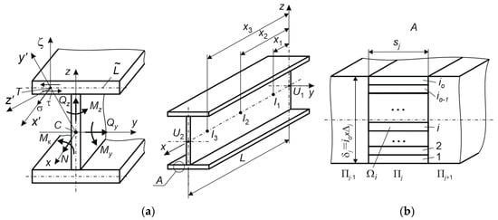
Figure 3.
Generation of a deformation model for an I-beam; forces and coordinates of integration points (a); the scheme of partitioning into prisms and layers (b).
Let us formulate the deformation matrix of this finite element as follows:
where (k = 1, …, 8) are elements of row matrix .
Here,
I is the total number of layers in the finite element; is the matrix that ensures the transition from the system of axes Oxyz to the system of axes .
Taking into account the approximation of displacements inside the finite element using a cubic polynomial, the matrix can be formulated as follows:
Taking into account the multilayered structure of the element, the elasticity matrix can be formulated as follows:
where is the secant torsional stiffness of the beam cross-section; are secant moduli of elasticity and cross-sectional areas of layers.
The stiffness matrix of the finite element is found as follows:
where are the coordinates of sections shown in Figure 3 and are the weight coefficients of the Gaussian quadrature formula of the fifth order, corresponding to these coordinates. The total stiffness matrix (9) is determined by the sum of matrices .
2.2.4. Modeling Soil-Base Deformations
The subsidence of the deformable soil base is prevented by designing foundations, whose areas are determined by the pressure condition:
where is the average value of pressure on the soil at the contact between the foundation base and the soil; is the pressure on the soil at the edge of the foundation base, perpendicularly to the plane of action of the maximum bending moment, transferred to the foundation; R is the design resistance of the soil base, determined experimentally or according to SP 22.13330.2016 “Soil bases of Buildings and Structures” [42].
The soil base is simplified as beam elements whose area equals the foundation area and whose depth is found using the following condition:
where is the active pressure triggered by external loading (foundations, building structures, etc.) at depth ; is the pressure of the natural soil weight at depth ;
Foundations must be designed so that they meet the conditions of strength, the safety of reinforcement (conditions of acceptable cracking and crack opening), and the prevention of column punching. Towards this end, design solutions require the preset concrete grade, foundation thickness, and reinforcement. When impact effects are analysed, the stress–strain state of the foundation is not taken into account and the foundation is conveyed in the model as an absolutely rigid body. In the course of normal operation, the required soil-base stiffness can be ensured by the following condition
and are vertical and horizontal deflections resulting from the combined deformation of the steel moment frame and the soil base; is the acceptable value of the soil-base settlement according to the standards of soil mechanics; and are acceptable values of vertical and horizontal displacements of structural elements, regulated by aesthetic requirements.
In an emergency situation, triggered by impact effects, it is assumed that the vertical component of an impact and emergencies, triggered by such impacts, do not cause nonlinear soil deformations. Therefore, a simplified approach, stemming from the basic principles of GAP rod elements and described in [33], is employed to simulate the failure of a portion of the soil, being part of the “soil base-structure” system, to take loads. We will use this modified scheme in the calculations made in the quasi-static formulation (Figure 4).
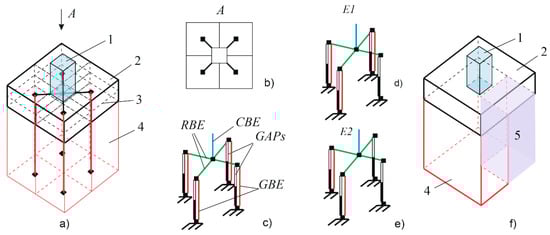
Figure 4.
Modelling the deformation of soil bases: (a) the general scheme: 1—steel column, 2—foundation, 3—median surface of the foundation, 4—soil base; (b) view A; (c) finite-element types: RBE—rigid body element; CBE—column beam element; GBE—elastic beam element for soil modelling; GAP—elements simulating actual gaps emerging due to soil removal; (d,e) probable emergency situations E1 and E2 caused by the soil base removal; (f) interpretation of situation E1: 5—the portion of soil removed as a result of an emergency situation.
A gap element, having the size of the gap equal to the size of the projected settlement, will be introduced into every joint of an elastic rod element, used to model the soil base. The tensile stiffness of this element is set as being close to zero (for loose soil), while its compressive and shear stiffness values are selected to prevent displacements.
3. Results
3.1. Experimental Verification of the Calculation Model
The quasi-static approach was verified according to the following procedure. An impactor, having a mass of , was dropped from various heights on the test bench (Figure 5). The maximum value of on rod 2 near connector 7 was recorded using the vibration graph; later, it was compared with the value obtained in the course of the quasi-static calculation. Mechanical characteristics of steel were identified experimentally. The yield strength value was found by rupturing tubes in the friction clamps and it was 580 MPa. Relative deformations were 0.023. The calculation model verification results are shown in Table 1.
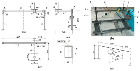
Figure 5.
Diagram of the test bench: (a) manufacturing drawings, (b) photo of the specimen, (c) calculation scheme; 1–4—frame rods, 5—angular connectors, 6—supplementary stiffening ribs, 7—connector of rods 2,4; 8—impactor, 9—guide bar, TP-1…TP-4—strain-gauge indicators.

Table 1.
Comparison between calculated and experimental data.
The table shows that the quasi-static approach differs from dynamic testing experiments by no more than 11%, which can be considered satisfactory. Therefore, the quasi-static calculation can be used to identify the value of loading on the basis of precalculated dynamic ratios, as suggested in Section 2.1.1. Moreover, it is necessary to reduce the labor intensity of calculations and the final version can be additionally verified by direct dynamic analysis.
3.2. Example of a Steel-Frame Calculation
3.2.1. Design Input Data
Let us consider the steel moment frame of a building, whose geometry is shown in Figure 6a. The cross-section of the columns is made W12 × 12 × 65; the cross-section of the I-beams is made W14 × 16 × 193 (ASTM); horizontal crossbars and diagonal bracing are made of 150 × 150 × 5 pipe (EN 10210). The material of the rods is structural steel with the yield strength equaling 250 MPa and the modulus of elasticity equaling 200 hPa. The foundations have dimensions of 1.8 × 1.4 m. The soil base is coarse sand with the design resistance of 500 kPa, the modulus of deformation of 50 Mpa, and the shear modulus of 20.83 Mpa. The behaviour of the materials follows bilinear deformation diagrams with a tangent modulus of 100 Pa, which is set to raise the stability of the numerical integration process. The change of loading in time is shown in Figure 6b–e.
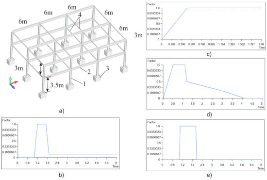
Figure 6.
Initial calculation scheme (a): 1—columns, 2—I-beams, 3—soil base, 4—horizontal cross bars; shapes of force pulses triggered by: angular impact loading (b), static loading (c), soil-base responses (d), and horizontal impact loading (e).
The following loading values were used in the calculations: the loading is uniformly distributed in the slab and it equals 14.66 kPa. This loading includes both dead loads, or the weight of the steel structures and the floor slab, and the live load. The horizontal pulse intensity (to be further referred to as IH), which, in particular, can describe a car hitting a column, is taken as being equal to 500 kN, while the angular pulse intensity (to be further referred to as IA) is taken as the vertical component equaling 948.6 kN and the horizontal component equaling 547.6 kN, which corresponds to angle to the vertical axis.
Such loading can be created, in particular, by an airborne vehicle falling on a building. Finally, the loading, resulting in (a) the inability of half of the soil-base area under the foundation to take any load and (b) the pulse transfer to the foundation according to scheme E2 of Figure 4e (IG), was considered. Its maximum intensity was assumed to be the same as for loading IA.
3.2.2. Impact Modeling, Solution Algorithm, and Problem Limitations
Impacts on the steel moment frame were predesigned using a generator of random application spots and pulse-loading directions. For IH loading, the “toward the frame” direction was assumed, and the height was fixed at 1 m. Due to the symmetry of the frame, for IA loading directions, the following three options were chosen from: along the x-axis, along the z-axis, and at the angle of 45 degrees to those axes. For IG loading, two possible options were considered. The first one was to prevent half of the soil-base area, located along the long side of the foundation, from taking loads; the second one was to prevent half of the soil-base area, located along the short side of the foundation, from taking loads. Disjoint subsets ,, were formed for the set of values of the load application spots (Figure 7). Arrows in Figure 7a show the potential direction of loading; the area of the soil base under the foundation that can no longer take any loads is shaded in gray.
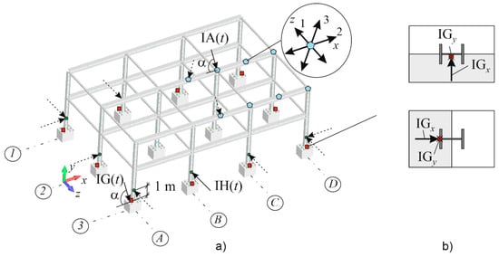
Figure 7.
Accidental loading by static equivalents of dynamic impacts IH(t), IG(t), and IA(t) (a): 1,2,3 are the planes in which IA load is applied; IGx and IGy are projections of the static equivalent of IG(t) loading on the corresponding coordinate axes (b).
The strength conditions according to the Von Mises stress theory (4), stiffness (6), stability (10), and survivability (5), were taken as loading limitations applicable to all loads. The solution search algorithm consisted of the following steps:
- –
- selection of IA loading positions from the set; analysis of the structure in the quasi-static formulation using the methodology described in Section 2.2.3, and verification of limitations. If limitations are violated, then the process is stopped and the system topology is refined or the cross-sections of rods are increased;
- –
- selection of IH loading positions from the set and analysis of the construction obtained at the previous step; verification of limitations. Enhancement of the structural solution, if necessary;
- –
- selection of IG loading positions from the set; verification of limitations with the subsequent enhancement of the design solution, if necessary;
- –
- verification of the solution using the detailed dynamic analysis, in terms of those loads, that require changes in the design.
The calculations were performed using the Simcenter Femap 2021 software package. For dynamics analysis, a solver implementing an implicit integration scheme was used. The dynamic process was considered as transient. The total integration time was 6 s and the initial time-integration step was assumed to be 0.05. As a convergence criterion, we used the nodal force mismatch, the value of which should not exceed 0.001.
The state when the stiffness matrix of the system ceased to be positively defined was taken as the failure criterion. The soil was modelled using the Winkler scheme. The physically nonlinear behaviour of steel was described by a Prandtl diagram with a tangent modulus of elasticity of 100 MPa and the limiting relative strains were limited to 0.05. Large deflections and rotation angles were taken into account in the calculation. Soil deformations were not limited.
3.2.3. Results of Calculation and Analysis of Mechanical Safety
Emergency impact calculations of a steel moment frame and the verification of the survivability condition are provided in Table 2. Here, the position of the spot of impact is provided in accordance with the axes in Figure 7.
Table 2.
Results of calculations.
The analysis of the results of quasi-static calculations shows that the effects, triggering the inability of the soil base to take loads, are the least dangerous for the preset dimensions of foundations; but, the soil behaviour becomes plastic in cases of other impacts. This factor should be necessarily taken into account in impact calculations. Horizontal and vertical impacts result in the need to add diagonal bracing to meet the survivability condition. Here are some results of verifications, made in the dynamic formulation and based on the equations from Section 2.2.2 (see Figure 8). The structural damping coefficient is applied to the soil material; the total damping of the frame–soil system, taking into account its deformable soil base, is .
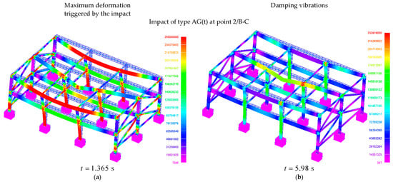
Figure 8.
Dynamic analysis of a steel frame subjected to an impact: (a) von Mises equivalent stress distribution for the peak loading value; (b) the same, but for the stabilized state of the structure after the impact.
Calculations show that the spots of impact loading and joints suffer from higher damage. Therefore, it is very important to ensure their predictable operation to implement catenary deformation during the transfer of the flow of forces from the spot of impact to the base. It is necessary to take into account the nature of the behaviour of structural elements within the time frame of dynamic analysis. Graphs can be used here. Figure 9a shows the graphs of stress change in time for the spot of impact and Figure 9b has graphs describing the compressed corner point of the soil base of the structure subjected to the impact according to Table 2.
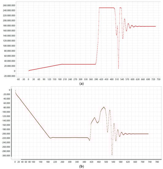
Figure 9.
A change of stresses in time: (a) point 2/B-C, impact AG(t), equivalent von Mises stresses (time steps are plotted along the x-axis, each step equals 0.008275 sec; (b) soil under the foundation 3/C, corner point in the direction.
Let us perform the safety analysis of the design solution using Formula (1). Let us consider the distribution of equivalent stresses over elements N. It is shown in Figure 10a. This figure and Figure 8 and Figure 10 have the finite-element number on the horizontal axis. The numbers are not shown; the whole system consists of 763 elements. Since the frame is made of the same grade steel, MPa for all elements; the second inequality of the system is satisfied. Then, the value of the integral strength margin for this loading will be . The calculation can be made by exporting the data to MS EXCEL. The theoretical safety level, at which the material consumption rate is minimum, can be calculated, assuming that MPa. We obtain
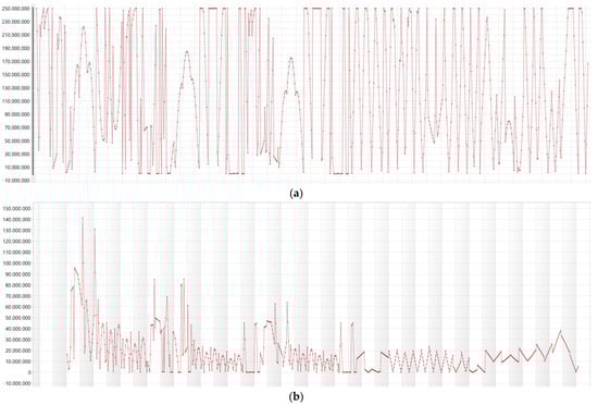
Figure 10.
Element-by-element safety-margin diagram of the under the impact of AG(t), (a); in case of normal operation (b).
This coefficient can be used for static loading. Given that the dynamic ratio is taken into account, the minimum acceptable material flow rate will be , if safety is ensured. This value is close to . It means that material consumption cannot be reduced and this impact is the most dangerous (if survivability is ensured). Therefore, the results of a further search cannot be considered. In the case of normal operation, the safety-margin diagram is shown in Figure 10b, which allows calculating . That is, in case of accident-free operation, the system is safe and the consumption of material can be reduced.
In the general case, it is necessary to consider all loads and find the minimum value using Formula (1). It is not recommended to design structures if the integral coefficient differs from the minimum theoretical one by less than 4%.
4. Discussion and Prospects for Further Research
The algorithm for the generation of an impact on a steel moment frame may fail to take into account the most dangerous combination of impact-loading parameters. Indeed, there is no method to determine these parameters other than the exhaustive enumeration of all options. However, we propose solving this problem by introducing integral safety margins and unifying structural elements due to their symmetry. The elements with the lowest safety margins are to be unified; their characteristics will be improved to ensure safety. Unification conditions imply the same cross-sections for a group of structural elements [43].
In the case of the local base subsidence, a slab foundation or a combined slab–pile foundation can be recommended to ensure safety in case of accidental impacts. Such a foundation will contribute to the effective distribution of forces in the adjacent columns and prevent the local subsidence of the soil base. Alternatively, local stabilization of soil can also be performed under the foundations to prevent soil failure and the subsequent failure of the steel moment frame. The algorithm [33] can be used to simulate such a method of soil stabilization.
The research, addressed in this paper, has broad prospects. The following issues are to be studied:
- –
- consideration of reinforced concrete frames of buildings and structures under accidental impact loads and effects;
- –
- consideration of methods for modelling low-velocity impacts on structures by a heavy mechanical body as a result of the collapse of a prefabricated slab, falling off a destroyed part of the structure on its undamaged part, etc.;
- –
- modelling of accidental thermomechanical effects on structures;
- –
- consideration of reinforced concrete and steel-frame systems subjected to the effects of combined repetitive accidental impacts.
Accounting for impact effects on the structure, which are random in nature, implies a large number of calculations. In each of these calculations, it is necessary to take into account the dynamic formulation of the problem, physical nonlinearity of materials, large displacements, and rotation angles. In this regard, an effective method of predicting the stress–strain state of structures is required. Currently, machine learning and neural network technologies can be such tools. In future research, it is planned to train a model based on linear regression by stochastic gradient descent. In this case, as “weights” of linear regression, it is supposed to use the coefficients describing the curve of deflections in the system as a result of shock impacts. This will make it possible to predict the behaviour of the system under shock impact, as well as to identify the shock-impact parameters under certain adaptations of the algorithm. The point of impact, direction, and intensity of impact can be taken as such parameters.
5. Conclusions
An approach to the safety analysis of steel moment frames, subjected to accidental impacts under uncertain conditions, was developed, including:
- –
- the procedure of generating pulse impacts on a steel moment frame, simulating a high-velocity concentrated impact, which approximates the impact of an absolutely rigid body having a small mass;
- –
- quasi-static and dynamic calculations of steel moment frames, subjected to impact effects, taking into account the physical and geometrical nonlinearity and criteria of resistance to progressive collapse;
- –
- the algorithm for evaluating the effectiveness of the designed structure using the cost minimization criterion while ensuring the required mechanical safety;
- –
- the method for taking into account local damages of the soil base subjected to the impact effect.
An equivalent stress characteristic of the integral safety margin is introduced. Its analysis for steel moment frames shows that the safest structural systems, subjected to inelastic impacts, have values of 0.6–0.8, which can be used for practical design purposes.
The studies have shown that, for the considered structure, if the soil stiffness is within 300–500 kPa, the resistance of the frame to progressive collapse can be increased by installing additional elements in the topology of the structure. If the soil stiffness exceeds 500 kPa, it is necessary to design joints with energy-dissipating elements. In this case, the finite-element modelling procedure requires minor integration steps and becomes very computationally demanding.
Funding
Order 453/130 of 15.05.2023 “On the implementation of projects supported by the results of the competition in 2023 for fundamental and applied scientific research (R&D) by scientific teams of Moscow State University of Civil Engineering”.
Institutional Review Board Statement
Not applicable.
Informed Consent Statement
Not applicable.
Data Availability Statement
The data presented in this study are available on request from the corresponding author.
Conflicts of Interest
The author declares no conflict of interest.
References
- Majlesi, A.; Asadi-Ghoozhdi, H.; Bamshad, O.; Attarnejad, R.; Masoodi, A.R.; Ghassemieh, M. On the Seismic Evaluation of Steel Frames Laterally Braced with Perforated Steel Plate Shear Walls Considering Semi-Rigid Connections. Buildings 2022, 12, 1427. [Google Scholar] [CrossRef]
- Xiao, Y. Development of Structural Testing Equipment for Impact and Complex Loading. J. Struct. Integr. Maint. 2021, 6, 1–15. [Google Scholar] [CrossRef]
- Zeinoddin, M. In-Situ Quasi-Static and Dynamic Behavioural Response of Steel Tubular Frames Subjected to Lateral Impact Loads. Lat. Am. J. Solids Struct. 2012, 9, 1–19. [Google Scholar] [CrossRef]
- Wang, H.; Huo, J.; Elchalakani, M.; Liu, Y.; Zhang, S. Dynamic Performance of Retrofitted Steel Beam-Column Connections Subjected to Impact Loadings. J. Constr. Steel. Res. 2021, 183, 106732. [Google Scholar] [CrossRef]
- Chen, K.; Yang, B.; Tan, K.H. Behaviour of Composite Beam-Column Joint with Fin Plate Connection Subjected to Impact Loads. Eng. Struct. 2022, 273, 115143. [Google Scholar] [CrossRef]
- D’Antimo, M.; Latour, M.; Demonceau, J.F. Drop-Weight Impact Tests on Free from Damage Beam to Column Connections. J. Constr. Steel. Res. 2022, 192, 107215. [Google Scholar] [CrossRef]
- Qiao, H.; Luo, C.; Ma, Y.; Chen, Y. Dynamic Effect Analysis of Steel Frame Structure under Impact of Falling Block. J. Vib. Shock. 2021, 40, 8–15. [Google Scholar] [CrossRef]
- Sadeghi, A.; Kazemi, H.; Samadi, M. Reliability and Reliability-Based Sensitivity Analyses of Steel Moment-Resisting Frame Structure Subjected to Extreme Actions. Frat. Integrita Strutt. 2021, 15, 138–159. [Google Scholar] [CrossRef]
- Mirkarimi, S.P.; Mohammadi Dehcheshmeh, E.; Broujerdian, V. Investigating the Progressive Collapse of Steel Frames Considering Vehicle Impact Dynamics. Iran. J. Sci. Technol. Trans. Civ. Eng. 2022, 46, 4463–4479. [Google Scholar] [CrossRef]
- Sadeghi, A.; Kazemi, H.; Mehdizadeh, K.; Jadali, F. Fragility Analysis of Steel Moment-Resisting Frames Subjected to Impact Actions. J. Build. Pathol. Rehabil. 2022, 7, 26. [Google Scholar] [CrossRef]
- Kou, S.; Zhang, X.; Li, W.; Song, C. Dynamic Response Parameter Analysis of Steel Frame Joints under Blast Loading. Buildings 2022, 12, 433. [Google Scholar] [CrossRef]
- Moon, N.N. Prediction of Blast Loading and Its Impact on Buildings. Master’s Thesis, Department of Civil Engineering, National Institute of Technology, Rourkela, India, 2009. [Google Scholar]
- Wang, H.; Huo, J.; Liu, Y.; Wang, N.; Elchalakani, M. Experimental and Numerical Study on Impact Behavior of Beam-Column Substructures of Steel Frame. Structures 2021, 29, 14–29. [Google Scholar] [CrossRef]
- Stochino, F.; Attoli, A.; Serra, M.; Napoli, A.; Meloni, D.; Mistretta, F. Structural Identification from Operational Modal Analysis: The Case of Steel Structures. Buildings 2023, 13, 548. [Google Scholar] [CrossRef]
- Gusella, F.; Orlando, M.; Peterman, K.D. The Impact of Variability and Combined Loads on Fuses in Braced Frames. Structures 2022, 35, 650–666. [Google Scholar] [CrossRef]
- Wang, H.; Tan, K.H.; Yang, B. Impact Resistance of Steel Frames with Different Beam–Column Connections Subject to Falling-Floor Impact on Various Locations. J. Struct. Eng. 2021, 147, 04021017. [Google Scholar] [CrossRef]
- Sadeghi, A.; Kazemi, H.; Samadi, M. Single and Multi-Objective Optimization of Steel Moment-Resisting Frame Buildings under Vehicle Impact Using Evolutionary Algorithms. J. Build. Pathol. Rehabil. 2021, 6, 21. [Google Scholar] [CrossRef]
- Nakatsuka, S.; Sato, A. Experimental Study on Shallow H-Shaped Steel Column under Combined Loading Condition. In Current Perspectives and New Directions in Mechanics, Modelling and Design of Structural Systems; CRC Press: London, UK, 2022; pp. 900–906. [Google Scholar]
- Brandis, A.; Kraus, I.; Petrovčič, S. Nonlinear Static Seismic Analysis and Its Application to Shallow Founded Buildings with Soil-Structure Interaction. Buildings 2022, 12, 2014. [Google Scholar] [CrossRef]
- Brandis, A.; Kraus, I.; Petrovčič, S. Simplified Numerical Analysis of Soil–Structure Systems Subjected to Monotonically Increasing Lateral Load. Appl. Sci. 2021, 11, 4219. [Google Scholar] [CrossRef]
- Wei, D.; Suizi, J. Restoring Force Model for Composite-Shear Wall with Concealed Bracings in Steel-Tube Frame. Buildings 2022, 12, 1315. [Google Scholar] [CrossRef]
- Forcellini, D. A Novel Framework to Assess Soil Structure Interaction (Ssi) Effects with Equivalent Fixed-Based Models. Appl. Sci. 2021, 11, 10472. [Google Scholar] [CrossRef]
- Qiao, H.; Guo, Z.; Chen, Y.; Zhang, M.; Qiu, H.; Wang, Z. Anti-Progressive Collapse Analysis for Plane Steel Frame under Impact Load. J. Vib. Shock. 2022, 41, 176–184. [Google Scholar] [CrossRef]
- Kumar, A.; Muley, N.; Murnal, P.; Matsagar, V.A. Progressive Collapse Potential of Steel Frames Sustaining Post-Hazard Support-Yielding. In Recent Advances in Computational Mechanics and Simulations; Lecture Notes in Civil Engineering; Springer: Singapore, 2021; Volume 103. [Google Scholar]
- Li, G.Q.; Zhang, J.Z.; Li, L.L.; Jiang, B.H.; Yang, T.C.; Jiang, J. Progressive Collapse Resistance of Steel Framed Buildings under Extreme Events. Adv. Steel Constr. 2021, 17, 318–330. [Google Scholar] [CrossRef]
- Alekseytsev, A.V. Mechanical Safety of Reinforced Concrete Frames under Complex Emergency Actions. Mag. Civ. Eng. 2021, 103, 10306. [Google Scholar] [CrossRef]
- Wei, J.P.; Tian, L.M.; Hao, J.P.; Li, W.; Zhang, C.B.; Li, T.J. Novel Principle for Improving Performance of Steel Frame Structures in Column-Loss Scenario. J. Constr. Steel. Res. 2019, 163, 105768. [Google Scholar] [CrossRef]
- Bregoli, G.; Vasdravellis, G.; Karavasilis, T.L.; Cotsovos, D.M. Static and Dynamic Tests on Steel Joints Equipped with Novel Structural Details for Progressive Collapse Mitigation. Eng. Struct. 2021, 232, 111829. [Google Scholar] [CrossRef]
- Wang, F.; Yang, J.; Wang, X.E.; Azim, I. Study on Progressive Collapse Behaviour of Steel-Framed Substructures with Sheathed CFS Stud Infill Walls. J. Build. Eng. 2021, 42, 102720. [Google Scholar] [CrossRef]
- Qiu, L.; Lin, F.; Wu, K.; Gu, X. Progressive Collapse Resistance of RC T-Beam Cable Subassemblages under a Middle-Column-Removal Scenario. J. Build. Eng. 2021, 42, 102814. [Google Scholar] [CrossRef]
- Lu, X.; Zhang, L.; Lin, K.; Li, Y. Improvement to Composite Frame Systems for Seismic and Progressive Collapse Resistance. Eng. Struct. 2019, 186, 227–242. [Google Scholar] [CrossRef]
- Hadi, M.N.S.; Alrudaini, T.M.S. A New Cable System to Prevent Progressive Collapse of Reinforced Concrete Buildings. In Proceedings of the Structures Congress 2012, Chicago, IL, USA, 29–31 March 2012. [Google Scholar]
- Kiakojouri, F.; De Biagi, V.; Chiaia, B.; Sheidaii, M.R. Strengthening and Retrofitting Techniques to Mitigate Progressive Collapse: A Critical Review and Future Research Agenda. Eng. Struct. 2022, 262, 114274. [Google Scholar] [CrossRef]
- Radwan, M.; Kövesdi, B. Equivalent Geometric Imperfections for Local Buckling of Slender Box-Section Columns. Period. Polytech. Civ. Eng. 2021, 65, 1279–1287. [Google Scholar] [CrossRef]
- Rzeszut, K. Post-Buckling Behaviour of Steel Structures with Different Types of Imperfections. Appl. Sci. 2022, 12, 9018. [Google Scholar] [CrossRef]
- Qu, H.; Huo, J.; Li, A.; Jiang, Y.; Liu, Y. Experimental Study on Impact Behaviour of Steel Plane Tubular Frames. Thin-Walled Struct. 2017, 111, 210–223. [Google Scholar] [CrossRef]
- Alekseytsev, A.V.; Kurchenko, N.S. Safety of Reinforced Concrete Columns: Effect of Initial Imperfections and Material Deterioration under Emergency Actions. Buildings 2023, 13, 1054. [Google Scholar] [CrossRef]
- Oladazimi, A.; Mansour, S.; Hosseinijou, S.A.; Majdfaghihi, M.H. Sustainability Identification of Steel and Concrete Construction Frames with Respect to Triple Bottom Line. Buildings 2021, 11, 565. [Google Scholar] [CrossRef]
- Meshref, A.; El-Dash, K.; Basiouny, M.; El-Hadidi, O. Implementation of a Life Cycle Cost Deep Learning Prediction Model Based on Building Structure Alternatives for Industrial Buildings. Buildings 2022, 12, 502. [Google Scholar] [CrossRef]
- Savin, S.; Kolchunov, V.; Fedorova, N.; Tuyen Vu, N. Experimental and Numerical Investigations of RC Frame Stability Failure under a Corner Column Removal Scenario. Buildings 2023, 13, 908. [Google Scholar] [CrossRef]
- Tamrazyan, A.; Alekseytsev, A. Evolutionary Optimization of Reinforced Concrete Beams, Taking into Account Design Reliability, Safety and Risks during the Emergency Loss of Supports. In Proceedings of the E3S Web of Conferences, Tashkent, Uzbekistan, 18–21 April 2019; Volume 97. [Google Scholar] [CrossRef]
- Construction Regulations SP 22.13330.2016 “Soil Bases of Buildings and Structures”. N.M. Gersevanov NIIOSP—Institute of JSC SIC Construction. Approved: 16.12.2016 Ministry of Construction and Housing and Communal Services of the Russian Federation. Available online: https://meganorm.ru/Index2/1/4293747/4293747631.htm (accessed on 7 June 2023).
- Tamrazyan, A.; Alekseytsev, A.V. Optimization of Reinforced Concrete Beams under Local Mechanical and Corrosive Damage. Eng. Optim. 2022. [Google Scholar] [CrossRef]


Disclaimer/Publisher’s Note: The statements, opinions and data contained in all publications are solely those of the individual author(s) and contributor(s) and not of MDPI and/or the editor(s). MDPI and/or the editor(s) disclaim responsibility for any injury to people or property resulting from any ideas, methods, instructions or products referred to in the content. |
© 2023 by the author. Licensee MDPI, Basel, Switzerland. This article is an open access article distributed under the terms and conditions of the Creative Commons Attribution (CC BY) license (https://creativecommons.org/licenses/by/4.0/).