
Experimental Study on Axial Compressive Performance of Light-Steel Skeleton–Cement–Fly Ash Foam Wallboard

Abstract
:1. Introduction
2. Experimental Program
2.1. Material Characteristics
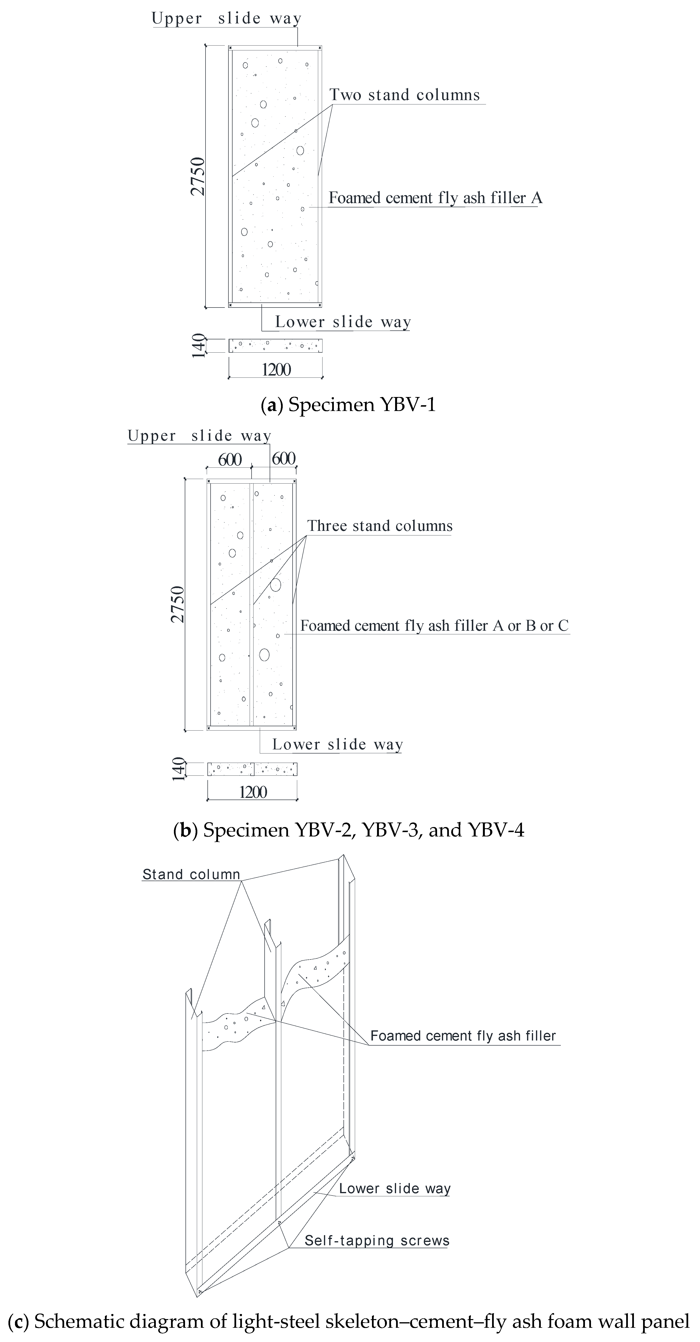
2.2. Experimental Design
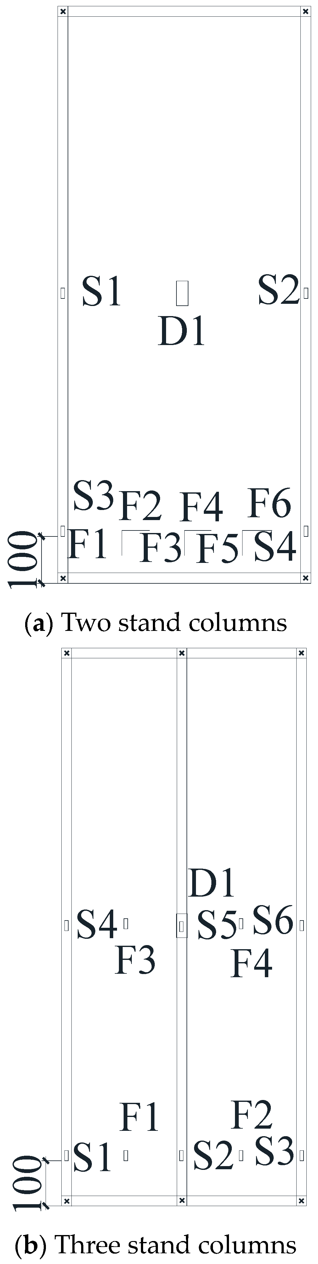
2.3. Sensor Placement
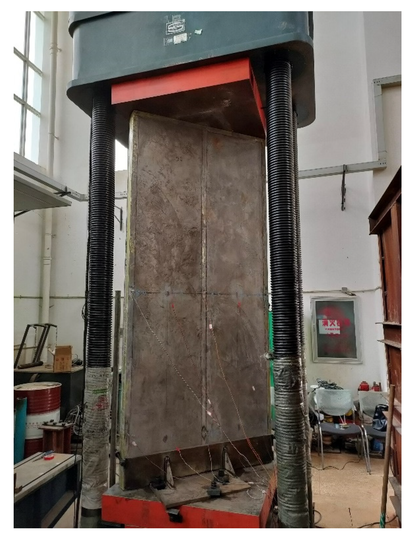
2.4. Experiment Setup and Loading Program
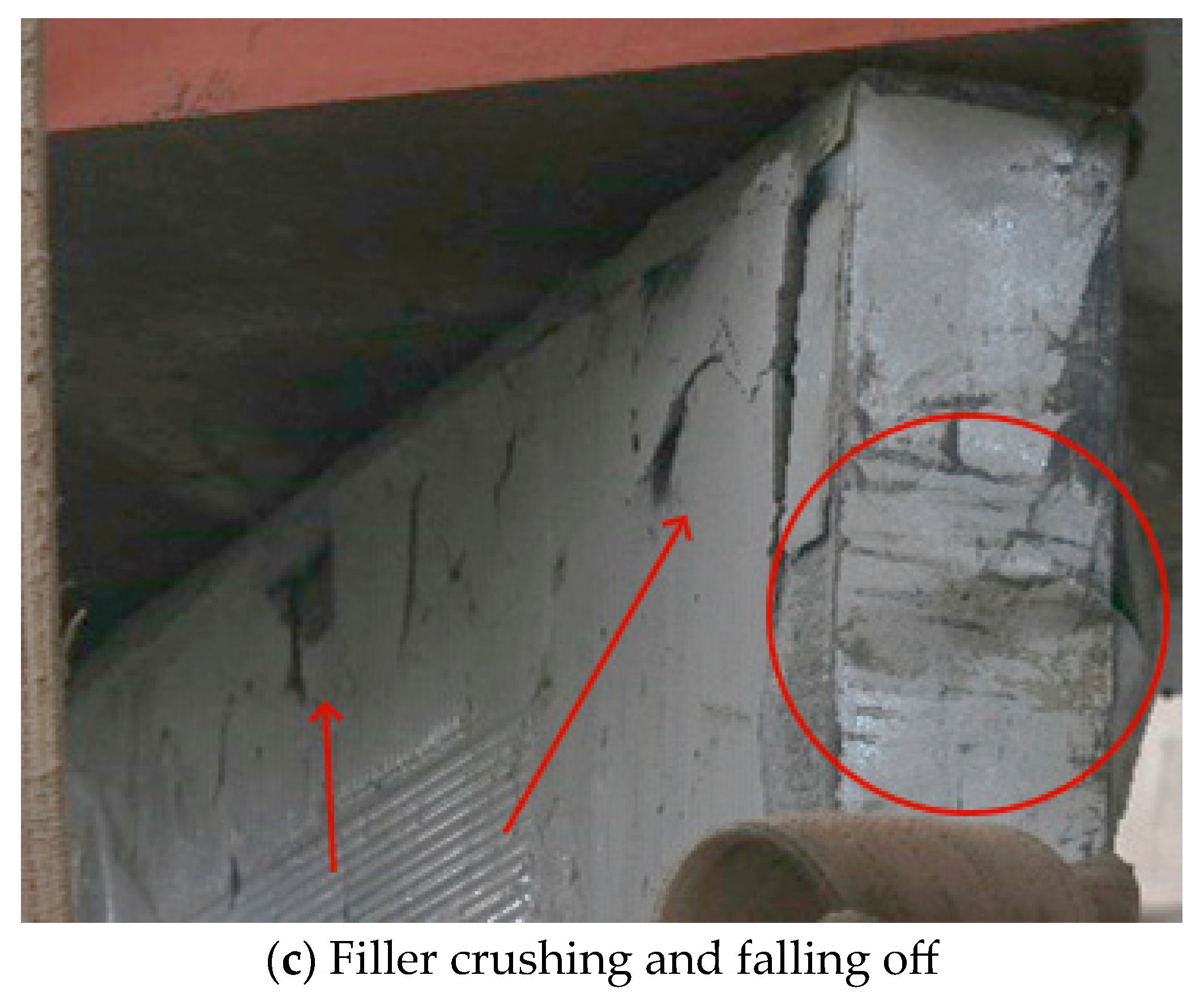
3. Specimen Failure Phenomenon and Characteristics
3.1. Specimen YBV-1
3.2. Specimen YBV-2
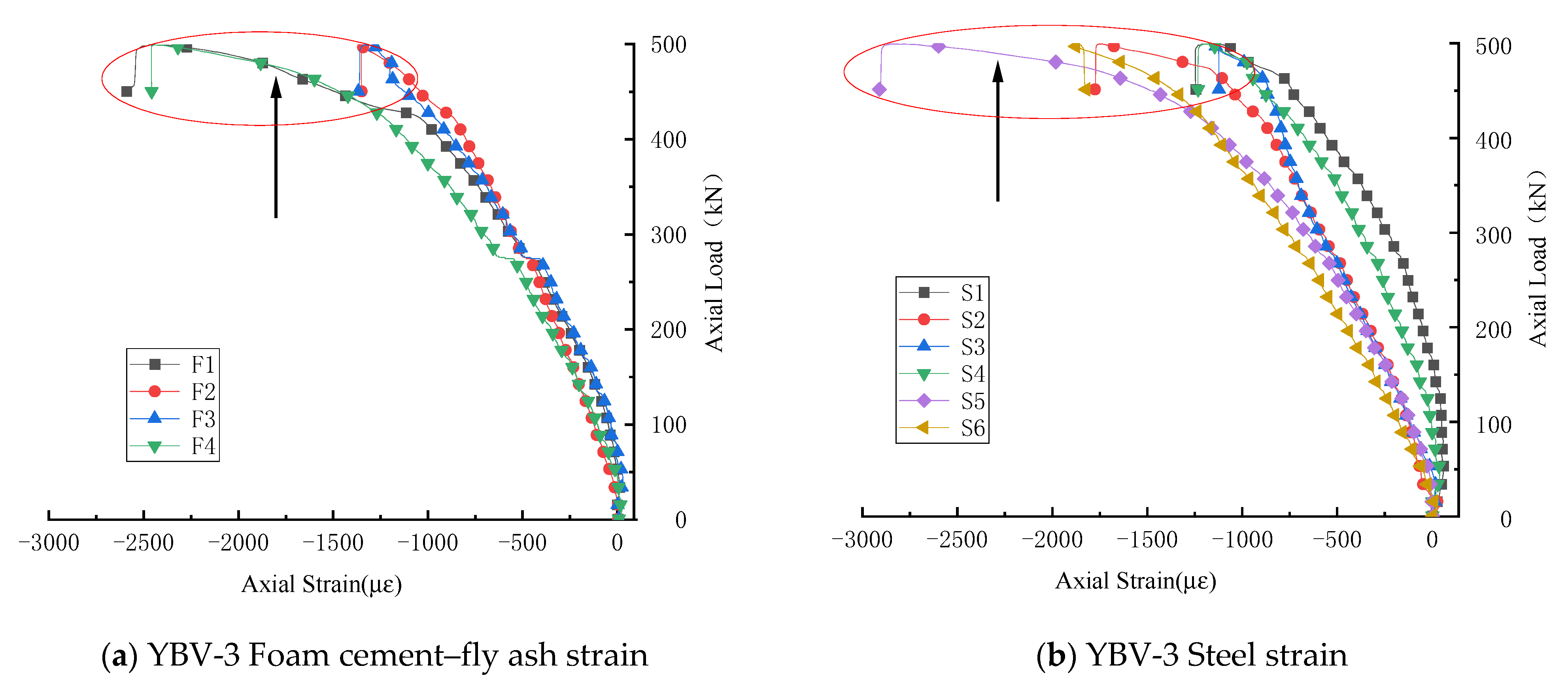
3.3. Specimen YBV-3
3.4. Specimen YBV-4
4. Experimental Results and Analysis
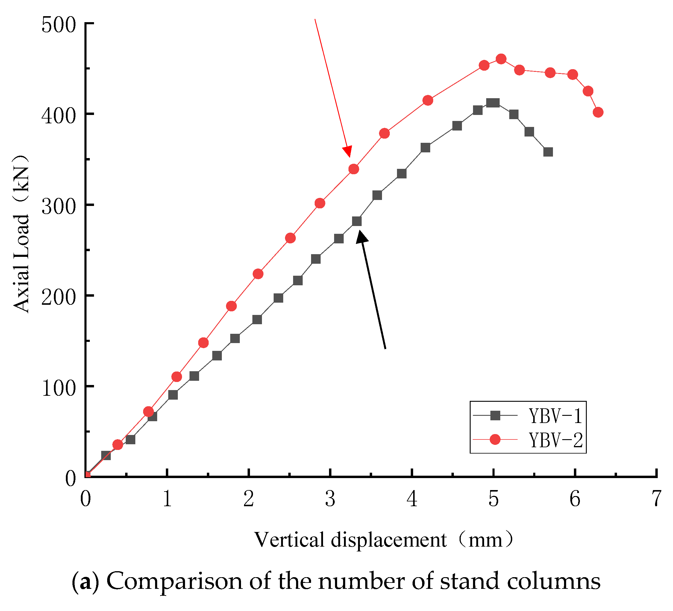
4.1. Effect of the Number of Columns on the Vertical Bearing Capacity of Wallboards
4.2. Effect of Polypropylene Fiber on the Vertical Bearing Capacity of Wallboard
4.3. Effect of the Cement–Fly Ash Foam’s Cement Content on the Vertical Bearing Capacity of Wallboard
5. Conclusions
- (1)
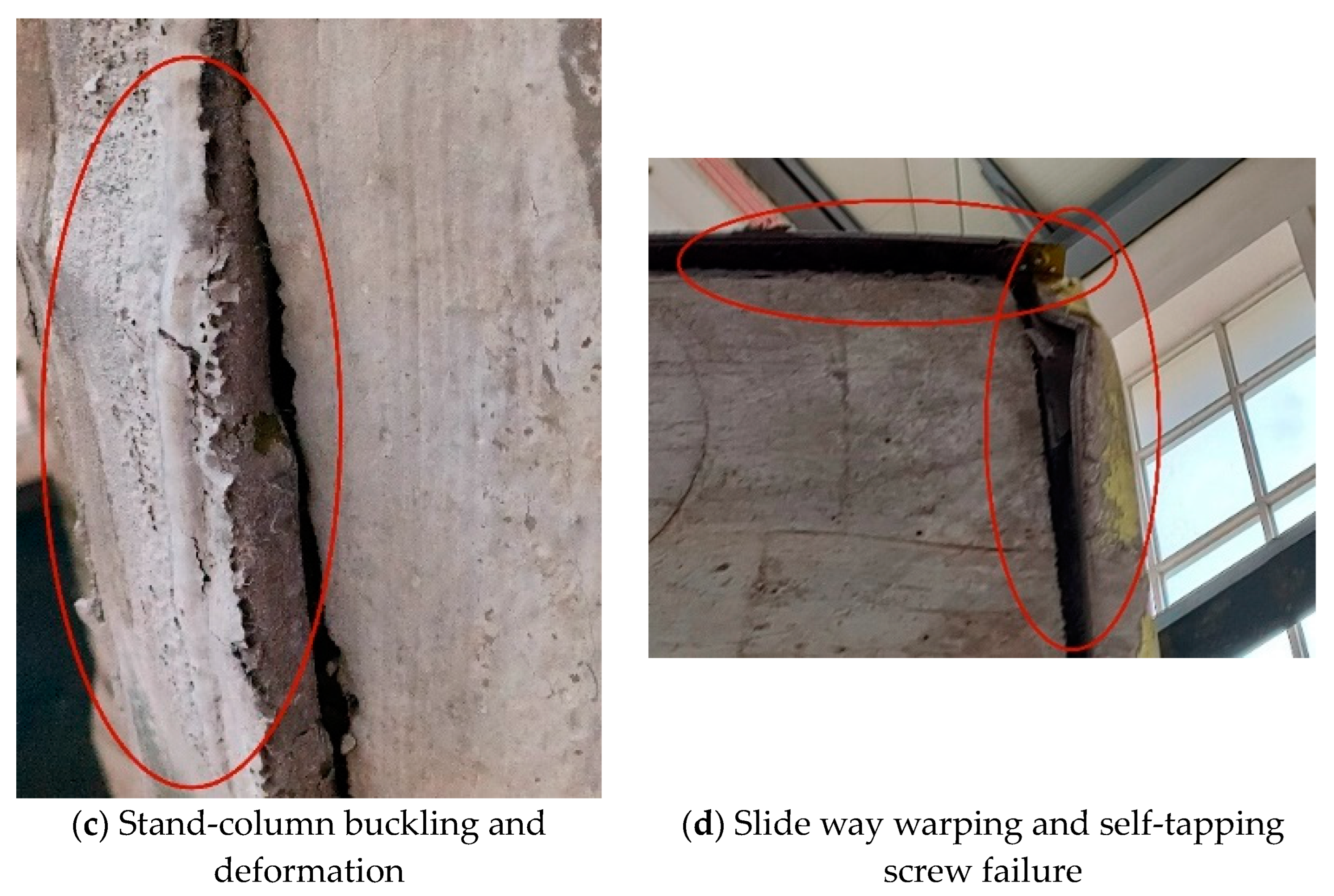
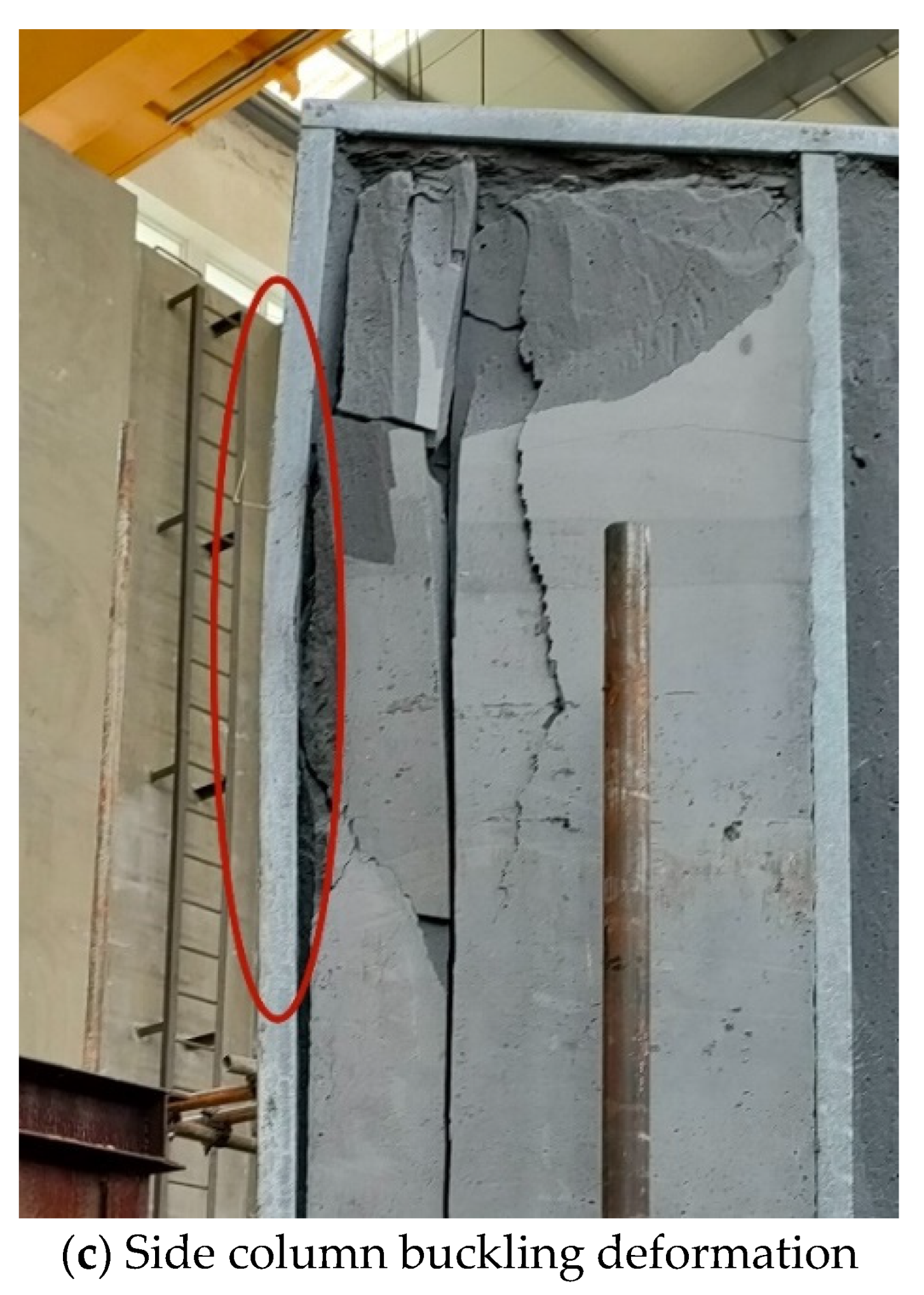
- The failure modes observed in the four tested wallboards were primarily column buckling and foam cement–fly ash filler crushing. Enhancing the axial compressive performance of the wallboards can be achieved through various means, such as increasing the number of stand columns, increasing the cement content, and incorporating polypropylene fibers.
- (2)
- Compared with the two-stand column LSSCFAFW, the vertical bearing capacity of the three-stand column composite wall panel is increased by approximately 12%. Additionally, by increasing the number of stand columns, the vertical bearing capacity and the safety stability of the LSSCFAFW are also improved accordingly.
- (3)
- Adding 0.4% polypropylene fiber in the LSSCFAFW has little effect on the vertical bearing capacity of the wallboard, which is only increased by 7.8%. However, the mixing of polypropylene fiber increases the bonding force of the filler and improves the deformation capacity and crack resistance of the wallboard. This inhibits the falling of the filler and enhances the integrity of the wallboard. Therefore, polypropylene fiber can be mixed in the wall panel to improve the integrity of the wallboard.
- (4)
- By increasing the cement content, the vertical bearing capacity of the LSSCFAFW can be effectively improved. This enhances the buckling and bending deformation resistance of the stand columns and strengthens the joint bearing effect of the filler, and the light-steel skeleton is enhanced. Compared with the composite wallboard, the vertical bearing capacity of the 50% cement content composite wallboard with 50% cement content is increased by approximately 56%. Furthermore, the elastic modulus of the foam cement–fly ash filler is doubled. This mitigates the negative impact of increased cost for the wallboard.
Author Contributions
Funding
Institutional Review Board Statement
Informed Consent Statement
Data Availability Statement
Acknowledgments
Conflicts of Interest
References
- Huang, Q.; Li, D.B.; Wang, J.J.; Chen, C.A.; Zhang, M. Study on lightweight steel and lightweight concrete structures system. J. Build. Struct. 2016, 37, 1–9. [Google Scholar] [CrossRef]
- Zhao, J.B.; Huang, S.; Fu, H.; Jiang, Y.; Chu, Y. Research on the application of light steel and lightweight concrete structures in rural housing. Constr. Wall Innov. Build. Energy-Sav. 2019, 12, 70–71. [Google Scholar] [CrossRef]
- Liu, W.; Zhou, E.Z. Summary of the development of light steel light concrete structural system. Sichuan Build. Mater. 2019, 45, 87–88. [Google Scholar] [CrossRef]
- Rybakov, V.; Seliverstov, A.; Raimova, I. Lightweight steel-concrete wall bearing structures under high-temperature exposure. In AIP Conference Proceedings; AIP Publishing: Melville, NY, USA, 2023; Volume 2612. [Google Scholar]
- Zhang, J.; Zhao, F. Applications of Light Steel and Light Concrete Structure System in Island Building. J. Coast. Res. 2020, 107, 73–76. [Google Scholar] [CrossRef]
- Hegyi, P.; Dunai, L. Experimental study on ultra-lightweight-concrete encased cold-formed steel structures Part I: Stability behaviour of elements subjected to bending. Thin-Walled Struct. 2016, 101, 75–84. [Google Scholar] [CrossRef]
- Dias, Y.; Mahendran, M.; Poologanathan, K. Axial compression strength of gypsum plasterboard and steel sheathed web-stiffened stud walls. Thin-Walled Struct. 2019, 134, 203–219. [Google Scholar] [CrossRef]
- Chen, J.W.; Fan, K.; Gao, L. Experimental study on axial compression performance of cold-formed steel framing walls with infilled gypsum based material. Build. Sci. 2018, 34, 48–53. [Google Scholar]
- Zhang, Z.N.; He, G.W.; Wang, C.G.; Kong, D.; Nie, L.; Liu, G. Experimental study on axial compression behavior of cold—Formed thin—Walled steel stud walls with stiffened—Web. J. Build. Struct. 2021, 42, 103–109. [Google Scholar]
- Vieira, L., Jr.; Shifferaw, Y.; Schafer, B.W. Experiments on sheathed cold-formed steel studs in compression. J. Constr. Steel Res. 2011, 67, 1554–1566. [Google Scholar] [CrossRef]
- Fratamico, D.C.; Torabian, S.; Zhao, X.; Rasmussen, K.J.R.; Schafer, B.W. Experimental study on the composite action in sheathed and bare built-up cold-formed steel columns. Thin-Walled Struct. 2018, 127, 290–305. [Google Scholar] [CrossRef]
- Ye, J.; Feng, R.; Chen, W.; Liu, W. Behavior of cold-formed steel wall stud with sheathing subjected to compression. J. Constr. Steel Res. 2016, 116, 79–91. [Google Scholar] [CrossRef]
- Foamed Concrete (JG/T 266–2011); China Industry Standard. Architecture & Industry Press of China: Beijing, China, 2011.
- GB/T 228.1-2010; National Standard of the People’s Republic of China. Metallic Materials—Tensile Testing—Part 1: Method of Test at Room Temperature. China Architecture & Building Press: Beijing, China, 2010.
- JGJ 383―2016; Technical Specification of Lightweight Steel and Lightweight Concrete Structures. China Architecture & Building Press: Beijing, China, 2016.
- JGJ 227―2011; Technical Specification for Low-Rise Cold-Formed Thin-Walled Steel Buildings. China Architecture & Building Press: Beijing, China, 2011.
- Prabha, P.; Marimuthu, V.; Saravanan, M.; Palani, G.S.; Lakshmanan, N.; Senthil, R.A. Effect of confinement on steel-concrete composite light-weight load-bearing wall panels under compression. J. Constr. Steel Res. 2013, 81, 11–19. [Google Scholar] [CrossRef]
- Wang, Z.Q.; Tan, K.F.; Xu, X.X. The Influence of Fiber on Properties of Foam Concrete. J. Southwest Univ. Sci. Technol. 2013, 28, 11–15. [Google Scholar]
- Zhang, X.S.; Zhu, Y.F.; Huang, L.C. Effect of polypropylene fiber on mechanical properties of foamed concrete. New Build. Mater. 2019, 46, 140–142+147. [Google Scholar]
- Zhang, X.H.; Zhang, E.Y.; Yu, H. Axial compression performance of coldformed thin-walled square steel stud-straw board composite wall. Sci. Technol. Eng. 2021, 21, 283–289. [Google Scholar]
- Xu, Z.F.; Chen, Z.F.; Zhu, S.S.; Liu, J.; Yin, Z.Q. Study of lightweight steel high-strength foamed concrete shear wall covered with straw board subjected to axial loading. Eng. Mech. 2018, 35, 219–231. [Google Scholar]
- Wu, H.; Chao, S.; Zhou, T.; Liu, Y. Cold-formed steel framing walls with infilled lightweight FGD gypsum Part II: Axial compression tests. Thin-Walled Struct. 2018, 132, 771–782. [Google Scholar] [CrossRef]
- Xu, Z.; Chen, Z. Experimental investigation on cold-formed steel foamed concrete composite wall under compression. Int. J. Civ. Environ. Eng. 2017, 11, 1257–1263. [Google Scholar]
- Xia, Q.; Ye, C.; Zhang, H.F. Study on foam concrete type light weight walling materials. Concrete 2010, 127–128+132. [Google Scholar]
- Qiu, J.F.; Luo, S.X.; Lu, H.; Sun, G.F.; Wang, Y.K. Study on ultra-light foamed concrete with high volume fly ash. New Build. Mater. 2013, 40, 74–76+79. [Google Scholar]
- Chen, L.Y.; Yang, A.; Hong, F.; Ma, Y.; Wang, J.; Qiao, H. Influence of different fly ash content on the performance and pore size of foamed concrete. Concrete 2021, 137–140. [Google Scholar]
- Zheng, N.N.; He, Z.; Sun, H.Y.; Wang, K.; Tong, M.D. Research on the Foamed Concrete with High Volume Fly Ash. J. Wuhan Univ. Technol. 2009, 31, 96–99+119. [Google Scholar]


| Filler Number | Dry Density/kg·m−3 | Compressive Strength/MPa | Elastic Modulus/MPa |
|---|---|---|---|
| A | 867.50 | 4.27 | 3587 |
| B | 826.20 | 4.60 | 3831 |
| C | 927.40 | 6.72 | 6653 |
| Steel Plate Thickness/mm | Yield Strength/MPa | Tensile Strength/MPa | Elastic Modulus/MPa | Elongation Rate after Fracture/% | Poisson’s Ratio |
|---|---|---|---|---|---|
| 1.00 | 728.60 | 738.80 | 2.07×10⁵ | 11.00 | 0.24 |
| Specimen Number | Number of Stand Columns/Piece | Filler Type |
|---|---|---|
| YBV-1 | 2 | A |
| YBV-2 | 3 | A |
| YBV-3 | 3 | B |
| YBV-4 | 3 | C |
| Specimen Number | Ultimate Bearing Capacity/kN | The Percentage Difference | Ultimate Displacement/mm | The Percentage Difference |
|---|---|---|---|---|
| YBV-1 | 412 | 5.01 | ||
| YBV-2 | 460 | +12% | 5.09 | +2% |
| YBV-3 | 496 | +8% | 6.07 | +19% |
| YBV-4 | 720 | +56% | 5.25 | +3% |
Disclaimer/Publisher’s Note: The statements, opinions and data contained in all publications are solely those of the individual author(s) and contributor(s) and not of MDPI and/or the editor(s). MDPI and/or the editor(s) disclaim responsibility for any injury to people or property resulting from any ideas, methods, instructions or products referred to in the content. |
© 2023 by the authors. Licensee MDPI, Basel, Switzerland. This article is an open access article distributed under the terms and conditions of the Creative Commons Attribution (CC BY) license (https://creativecommons.org/licenses/by/4.0/).
Share and Cite
Liu, C.; Bai, Y.; Jiang, X.; Su, H. Experimental Study on Axial Compressive Performance of Light-Steel Skeleton–Cement–Fly Ash Foam Wallboard. Buildings 2023, 13, 1928. https://doi.org/10.3390/buildings13081928
Liu C, Bai Y, Jiang X, Su H. Experimental Study on Axial Compressive Performance of Light-Steel Skeleton–Cement–Fly Ash Foam Wallboard. Buildings. 2023; 13(8):1928. https://doi.org/10.3390/buildings13081928
Chicago/Turabian StyleLiu, Chengcong, Yu Bai, Xinli Jiang, and Hexian Su. 2023. "Experimental Study on Axial Compressive Performance of Light-Steel Skeleton–Cement–Fly Ash Foam Wallboard" Buildings 13, no. 8: 1928. https://doi.org/10.3390/buildings13081928
APA StyleLiu, C., Bai, Y., Jiang, X., & Su, H. (2023). Experimental Study on Axial Compressive Performance of Light-Steel Skeleton–Cement–Fly Ash Foam Wallboard. Buildings, 13(8), 1928. https://doi.org/10.3390/buildings13081928