Abstract
The seismic performance assessment of heritage architecture presents many challenges due to the restrictions set forth by the conservation principles to protect the associated social and cultural values. These buildings are typically characterized by unreinforced masonry walls connected by tie-rods, vaults, and wooden floors. The era of construction dates to the time when seismic design regulations were largely unknown, making heritage structures potentially vulnerable to earthquake damage. This study presents the seismic performance assessment of the Jesuit College located in the southern part of the Old City of Dubrovnik. A series of field surveys were conducted to qualitatively examine the material composition and obtain geometrical details in part of the Croatian Science Foundation research project IP-2020-02-3531 entitled “Seismic Risk Assessment of Cultural Heritage in Croatia—SeisRICHerCRO”. The structural response is thoroughly investigated by means of a complex finite element model calibrated using the frequencies determined from ambient vibration measurements and material characteristics obtained from the literature review of representative cultural heritage buildings. The seismic performance is evaluated using linear static and response spectrum analysis in accordance with Eurocode 8 guidelines for the demand seismic action level. The numerical analysis indicates several structural components in the building exhibiting high shear stress concentration and exceeding the elastic tensile limit under the demand ground acceleration level. The assessment further reveals substantial out-of-plane bending of vulnerable wall components (identified by local mode shapes) at low peak ground acceleration levels. The stress concentration in numerous structural components leads to the identification of vulnerable zones where retrofitting measures are essentially required.
1. Introduction
Heritage architectures are typically characterized by their tall unreinforced masonry walls connected by ancient tie-rods, large span vaults, and wooden floors. The lack of seismic design considerations, non-existent or improper structural maintenance, and long-term exposure to physical deteriorating factors render these buildings particularly vulnerable to earthquakes, presenting an unacceptable risk to the general public and to the associated cultural and historical values. The structural performance evaluation of such buildings is a rather complex and difficult task, requiring the collaboration of multiple stakeholders including the owner, structural engineer, architect, and curator as well as the local and national authorities. The most crucial aspect is overcoming the challenges in obtaining the necessary input data which are either inaccessible, incomplete, improperly archived, or cannot be determined through experimental diagnosis owing to the regulations concerning the preservation of delicate architectural features [1,2,3]. The lack of a centralized database makes the data collection process complex, requiring extensive communication with multiple institutions/authorities and numerous approvals. Some of the main difficulties encountered while accessing the data (e.g., architectural drawings, material data, previous studies, etc.) are as follows:
- Distribution of data between multiple sources, including government institutions, archives, libraries, museums, and research centers, follows a series of inconsistent/non-uniform access regulations. Data fragmentation slows down the process of collecting and using valuable information;
- Content related to the cultural heritage is either non or partially digitized, requiring additional time and human resources;
- Data ownership (legal authority) is very often subject to intellectual property protection;
- Language barriers (e.g., Latin, ancient Greek, etc.), especially in the case of older records providing invaluable knowledge about the historical development of a cultural heritage asset.
The individuality of each cultural heritage building demands a thorough understanding prior to any conservation or strengthening actions. This understanding stems from an integrated approach encompassing a historical review, a geometric survey, and a diagnostic structural analysis. The historical review offers insights into the building’s chronology and construction, the geometric survey identifies physical parameters and existing conditions, while the diagnostic analysis assesses the structural system and material characteristics. Taken together, these elements enable reliable comprehension of the building’s structural behavior and provide a foundation for subsequent analytical or numerical methods, ensuring that the conservation efforts are tailored to the specific vulnerabilities of the case study [4,5].
Within the confines of limited input information, the seismic performance of cultural heritage can be evaluated through a combination of qualitative diagnosis and reliable computational models. Recent studies demonstrate the successful application of dynamic testing in conjunction with finite element modeling for the system identification, model calibration, damage prognosis, and maintenance/rehabilitation of cultural heritage buildings [6,7,8,9]. The finite element method (FEM) offers a robust approach to the modeling and analysis of cultural heritage buildings, effectively addressing their unique complexities that are often not captured by simpler methods. One of the predominant advantages of FEM is its ability to manage complex geometrical configurations, including the intricate forms of vaults and irregular floor plans, typical of historic architecture [10,11,12]. The numerical calibration process assists in determining the unknown structural parameters by minimizing the deviation between the experimental and numerical response of the structure. However, the reliability and accuracy of results depend on the selection of an appropriate set of parameters for model calibration and are typically based on a sensitivity analysis [13,14,15,16,17,18,19,20].
The current study focuses on the seismic evaluation of the 18th-century Episcopal Seminary building and Classical Gymnasium (formerly known as the Jesuit College) in the Old Town of Dubrovnik in Croatia (see Figure 1) [21,22]. Despite its unquestionable importance, the Jesuit College had never been rigorously investigated before the current research. Existing information was disorganized and sparse. The geometric data were confined to hand-drawn sketches from the 19th century and made based on direct visual observations and inspections. There was no current condition assessment or diagnostic testing performed on the structure. Adding to these complexities, the building’s stability might be compromised due to the region’s seismic activity, a concern that was underscored by the Great Dubrovnik Earthquake in 1667. In the present paper, a first step towards the earthquake assessment of the Jesuit College is presented.
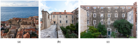
Figure 1.
Overview of the Jesuit College: (a) On the location within the Old Town; (b) East wing; (c) South wing (Photographic Collection of the Institute of Art History, Zagreb, photo by: Paolo Mofardin).
The Jesuit College is located in front of the monumental Jesuit Stairway and was originally designed by the Jesuit brother Serafino Fabrini, featuring Late Baroque Era architecture and decorative elements [22,23]. The construction started in 1662 and initially included a central church surrounded by a college. Halted by the great Dubrovnik earthquake in 1667, the development and expansion were undertaken by various architects and took more than a century to be completed in 1765 (see Figure 2). Today, the building hosts a Catholic gymnasium and is primarily used for educational purposes.
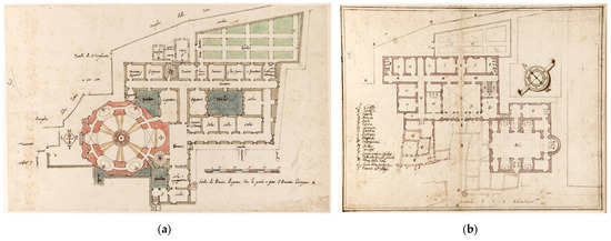
Figure 2.
Architectural drawings of the Jesuit college by (a) Serafino Fabrini in 1659; (b) Henri Lalojau in 1699, from the National Library in Paris [23].
2. Field Investigation
2.1. Material and Geometry
Historical construction on the Adriatic coast (Dalmatia) mainly consists of stone buildings (churches, cathedrals, palaces, family houses, residential buildings, etc.) with different textures (quality) of masonry influencing the material characteristics (see Figure 1 and Figure 3). The Jesuit College is classified as an unreinforced irregular stone masonry building that belongs to vulnerability class B in compliance with EMS-98 [24]. The masonry wall texture consists of irregularly crafted natural stone (predominant) or Roman brick units (seldom), alternately laid out in lime mortar (fully grouted). In addition to the available materials, ruins of the 1667 earthquake were also used in the reconstruction process. The non-homogeneous material composition is attributed to the different construction periods as well as the strengthening measures carried out in localized regions over the years. An intensive experimental program was carried out on the quality of walls in Dalmatia, particularly in the Old City of Dubrovnik, as described in the research project report [25]. The compressive strength of lime mortar (), the unit’s compressive strength (; ), the masonry’s compressive strength (), and elastic modulus () are determined based on the gathered information [26].
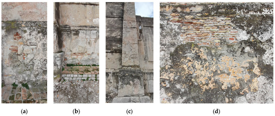
Figure 3.
The non-uniform material composition of the external walls and columns: (a) wall with irregularly integrated bricks and stones; (b) wall with integrated layers of brick and stone on top of each other; (c) column brickwork; (d) exposed external wall portion made of bricks (illustration source: Davorin Penava).
The building has a footprint of 57 m × 32 m with a total area of approximately 1690 m2. The ground, first, second, and third stories have an approximate inter-story height of 2.92 m, 5.30 m, 4.0 m, and 3.35 m, respectively. The wall height reaches up to a maximum of 22 m with the thickness varying within a range from approximately 70 cm to 105 cm. The roof structure is predominantly made of wood with no precise information available regarding the material properties. The wooden floors are covered with a light concrete cover of approximately 7 cm and are braced by wooden beams (depth range of 12 cm to 26 cm) either supported over the corbels or embedded into the adjacent walls. The cross-ribbed, cloister, and barrel vaults made of stone masonry support the floor system and represent one of the most important structural and architectural features of the building (see Figure 4). The complex geometry of the vaults is formed by multiple arch assemblies enchained together into a continuous surface. The iron tie-rods provide auxiliary support to the vaulted structure and walls against out-of-plane deformations. The presence, location, and position of tie rods indicate intervention activities (i.e., retrofitting, strengthening, etc.) throughout the building’s history [27].
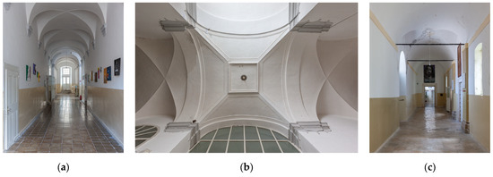
Figure 4.
Different types of floor vaults: (a) Cross ribbed; (b) Intersection of different types of vaults; (c) Vaults reinforced with iron tie-rods (Photographic Collection of the Institute of Art History, Zagreb, photo by: Paolo Mofardin).
2.2. Ambient Vibration Measurement
In assessing the seismic performance of the cultural heritage building, the determination of the stiffness of the structure (or individual structural elements) is an important task, often made difficult due to various influencing parameters, such as non-uniform quality of masonry workmanship (see Section 2.1), unknowns within or above the structural elements (thick walls, vaults, etc.), interconnectivity, and damage. The optimal solution in such cases is the calibration of a structural model utilizing vibrational characteristics of the building (natural frequencies), where the geometrical properties are known, and the material characteristics are determined by a trial-and-error process. To identify the natural frequencies, ambient vibration (noise) measurements were collected within the Jesuit College building in two ways: (1) Up to 20 min long (interim) at the 2nd and 3rd story (attic) using HVSR instruments (at five different locations per story); (2) Continuous over 3 days in the 2nd story using a SARA instrument (at one location). The north-south (NS), i.e., the longer direction of the building’s south wing (see Figure 5a,b), and east-west (EW) response components were simultaneously measured at a sampling rate of 128 Hz. The fundamental frequencies in NS and EW directions were determined from the Fourier amplitude spectrum of the two recorded horizontal components (see Table 1 and Figure 6). Since no experimental modes were identified, it is not possible to correlate the frequencies with structural mode shapes. Therefore, the measured frequencies are referred to as fNS and fEW for the measurements recorded in the NS and EW directions, respectively. The mean frequency is used as a reference for the calibration of the finite element structural model. The standard deviation (St. dev.), variance (Var.), and variation coefficient (Var. coeff.) indicate the range of variability in the measured response.
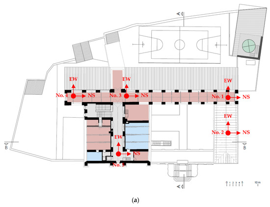
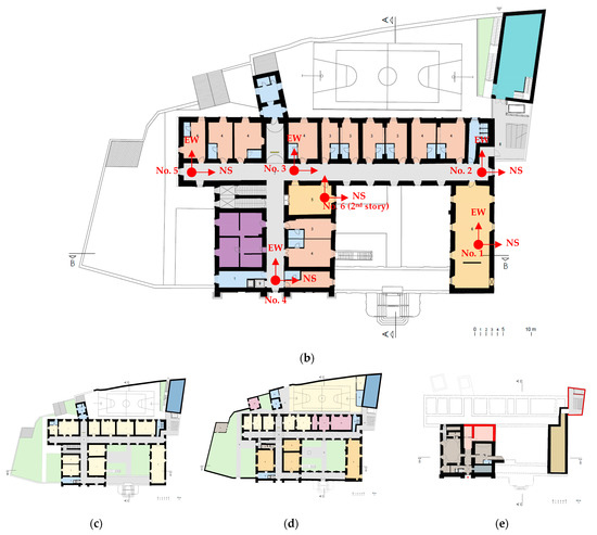
Figure 5.
Building plan with an overview of the sensor layout and direction (red): (a) 3rd story (attic); (b) 2nd story; (c) 1st story; (d) ground story; (e) basement.

Table 1.
Values of measured natural frequencies f (Hz) in the north-south (NS) and east-west (EW) directions [22,28].
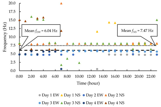
Figure 6.
Natural frequencies of the Jesuit College obtained from the continuous measurements at the 2nd story, position no. 6 (see Figure 5b) [22,28].
In addition to an overview of the sensor layout, Figure 5c–e provides an insight into the structural (stone) masonry wall disposition and irregularity of the building construction. The positions for the measurements were selected across the building to possibly verify the interconnectivity between different wings of the building (structural wholeness). The calculated coefficient of variation is approximately 34% for the 2nd story and 12.5% for the 3rd story (EW and NS) (see Table 1). The overall variation coefficient is approximately 30% for the EW direction and approximately 20% for the NS direction, which indicates irregular behavior of different parts of the building, variation in material properties, structural weaknesses, and material degradation. The natural periods of the building, based on the overall average frequencies, are 0.16 s in EW, and 0.13 s in NS, i.e., longer direction, respectively.
Figure 6 shows the variation in the natural frequencies of the building based on continuous measurements with overall mean frequencies as reference values. The occasional discrepancies occurred due to external factors and were not considered in the analysis of vibrational characteristics (4 Hz < f < 10 Hz).
3. Structural Modeling and Calibration
The building is modeled and analyzed using the finite element software DIANA v10.7 (see Figure 7) [29]. The influence of adjacent structures and the interaction among building sections built in different years is neglected based on a careful examination indicating separate entities rather than structural wholeness (representing constraint). The structural model is simplified further by excluding the basement since its contribution to the fundamental period is negligible. The walls and vaults are modeled using solid elements and elastic isotropic material properties. The initial material properties used for the finite element model are based on field investigations as well as an extensive literature review of similar masonry types (see Table 2) [30,31,32,33,34]. The timber floors and roof structure are modeled as isotropic shell elements allowing the transfer of bending effects due to the gravitational loads and in-plane stresses simulating the level of rigidity associated with a flexible diaphragm. The in-plane stiffness of the wooden structure and its components are represented by material properties taken from the literature with similar structural configurations [35,36]. The stiffness contribution of the spiral staircase is neglected in modeling since the surrounding walls are considerably rigid. The iron tie-rods are included as regular truss elements carrying a pre-stressing tensile force and allowing deformations only along the element axis.
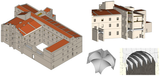
Figure 7.
Finite element model of the case study building.
Table 2.
Range of material properties adopted for model calibration (see Section 2).
The analysis of cultural heritage buildings often needs a balance between the level of detail and the availability of resources, including time and data. Detailed nonlinear analysis or anisotropic material modeling requires extensive data, which may not be readily available or obtainable due to the restrictions on intrusive investigations in such buildings. In such cases, the use of simplified linear analysis and isotropic material properties can provide a viable starting point for understanding the structural behavior and guiding further investigations or interventions. However, it is crucial to understand that these simplifications may not fully capture the complexities of structural behavior, particularly under strong seismic actions or for buildings with significant damage or deterioration. Therefore, these methods should be used as preliminary tools, and their results should be interpreted with caution [11,37].
The gravitational load applied to the structural model consists of permanent and variable actions determined in accordance with the requirements of the Eurocode and the corresponding Croatian National Annex [38]. The permanent actions consist of the self-weight, dead load of 0.55 kN/m2 from the concrete floor cover and an additional dead load of 0.69 kN/m2 applied to the roof. In addition to the snow load of 0.4 kN/m2, variable actions for building use category C are also considered. Since the design tensile force of the iron tie-rods is unknown, a force of 10 kN is considered based on the literature review of similar reinforcement techniques in historical masonry structures [39,40].
The finite element model mesh consists of 4-node hexahedral and quadrilateral volumetric elements for the solids and flat shell elements, respectively. The basic mesh element size is 0.5 m with a 65% transition smoothness for the edges and corners shaped by connecting members, i.e., vaults, wooden floors, etc. The mesh density is determined through a parametric calibration in conjunction with the convergence analysis of the dynamic response. The goal is to find the mesh density that provides a satisfactory level of accuracy in the model’s prediction of the dynamic response, without unnecessarily high computational cost. This optimal point is typically where the model’s results have “converged”, meaning that additional increases in mesh density lead to only minor improvements in accuracy. This approach is necessary because the dynamic response of historical masonry structures can be sensitive to the level of detail represented in the model. For instance, local behavior like stress concentrations requires a finer mesh to be accurately captured. Therefore, the mesh density needs to be calibrated to ensure it is sufficient for the specific analysis objective while maintaining reasonable computational efficiency. The final mesh has a total of 119,306 nodes from which 2659 are restricted at the base; 184,821 elements are distributed as 173,628 solid; 11,176 shell; and 17 truss elements.
Starting the model calibration process with a reference set of material properties not only provides a physical sense of the calibrated values but also optimizes the time required for convergence in the case of manual model calibration. The possible range of values considered for the material properties is summarized in Table 2. The unknown material parameters are restricted to the elastic modulus (E), density (ρ), and poison ratio (v) to reduce uncertainty in the calibrated parameters. The material parameter combinations are subjected to free vibration eigenvalue analysis to minimize the error between numerical and experimental dynamic response. The first eight analyses tested the sensitivity of each material parameter to the analytical response of the structure. It is observed that the model is highly sensitive to changes in the material density and the tendency of reducing error is directional dependent, i.e., the reduction in error in one direction (e.g., NS) leads to an increase in error in the other direction (e.g., EW). The calibrated masonry material properties with an error of 12.41% in NS and 13.91% in EW frequencies, respectively, are summarized in Table 3.
Table 3.
Calibrated stone masonry material properties.
The cumulative effective mass for the first six free vibration modes corresponds to approximately 70% in the NS and 72% in the EW directions. The accumulation of higher mass participation requires the calculation of a large number of modes, i.e., approximately 250 modes are required to accumulate 90% mass participation in both horizontal directions. The mode shape 1 (f1 = 5.17 Hz) represents a local vibration mode of the clock tower, indicating high expected deformations at a relatively low frequency. Mode shape 2 (f2 = 6.05 Hz) shows the global mode shape in the EW direction with 61% cumulative mass participation. Mode shape 3 (f3 = 6.78 Hz) represents the global mode shape in the NS direction with an effective mass participation of 56%. It is important to note that neither of the global mode shapes represents pure translation in either horizontal direction, accompanied by a significant translational motion in the orthogonal direction (see Figure 8). In the case of mode shapes 4–6, the concentrated deformations in various parts of the structure show potentially vulnerable zones even though these modes do not contribute significantly to the global dynamic response due to their relatively low mass participation.
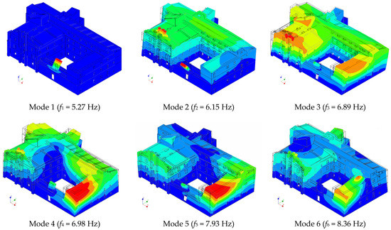
Figure 8.
Mode shapes obtained from the free vibration eigenvalue analysis.
The identified global modes which activate the major percentage of mass participation in EW and NS directions are selected for the model’s calibration. The global modes are primarily characterized by a translational motion activating significant mass participation in the horizontal directions (see Table 4). Despite the complex dynamic responses caused by irregular distribution of mass and stiffness (eccentricity ex = 3.8% and ey = 5.4%), the potential for torsional motion remains comparatively limited (indicated by the low effective rotational mass given in Table 4). In addition to the global mode shapes, the low-frequency local modes reveal the out-of-plane vibration of individual façade segments. These local modes help in the identification of the unwanted cantilever motion associated with the clock tower and gable wall which is used for the local verification in Section 4.2.
Table 4.
Translational and rotational effective mass as a percentage of the total mass of the structure (MT and MR).
4. Seismic Performance Assessment
4.1. Seismic Action
The City of Dubrovnik is located on the coast of the Adriatic Sea in the southern part of Croatia and on the boundary between the African and Eurasian tectonic plates which move towards each other causing high seismic/tectonic activity in the region. This region is the most threatened area in Croatia with the highest expected earthquake magnitude of M7.5. According to geological classifications, the area is located at the contact between the Adriatic and Dinaric regional structural units, defined by karstic terrain and porous limestone bedrock. The immediate border of these units is the Ploče–Dubrovnik fault. Between Mljet and the Dubrovnik submarine, the Adriatic unit borders the Adriatic microplate [41]. Earthquakes are a major concern of the region due to the high concentration of cultural heritage buildings of outstanding historical significance. Since the 1979 M7.0 Montenegro Earthquake, the Old City of Dubrovnik is enlisted in the UNESCO World Heritage List [42]. Historic data for the period BC–2021 (see Figure 9), according to the Croatian Earthquake Catalogue—CEC [43], note about ten earthquakes in the region with intensity VIII or more (°MCS) out of which the most significant is the 1667 earthquake of intensity X (°MCS) [44,45]. Before the Great Dubrovnik Earthquake of 1667, strong earthquakes from 373 BC, 376, 1471, 1482, 1504, 1516, and 1520 are mentioned, which caused damage to the area. Of the very strong or severe earthquakes from the recent past, there are those from 1850 and 1869 with an intensity of VII on the °MCS scale; however, the M7 earthquake in Montenegro from 1979 is particularly highlighted. In Dubrovnik, it manifested itself as an earthquake of intensity VII (°MCS) with structural damage to numerous buildings in the Old City, including the Jesuit College (see Figure 10a).
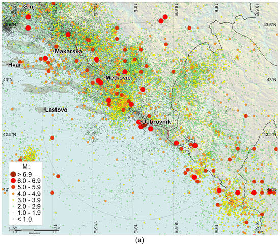
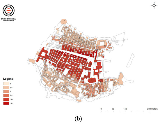
Figure 9.
(a) Spatial distribution of earthquake locations around the Dubrovnik area based on data from the Croatian Earthquake Catalogue (updated and continuously supplemented version first described in [43] for the period BC–2021. Circle marks the area inside 100 km from Dubrovnik); (b) seismic micro-zoning in compliance with MCS scale available at [46].
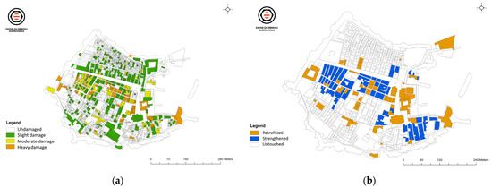
Figure 10.
The Old City of Dubrovnik following the 1979 M7 Montenegro earthquake: (a) state of damage to buildings; (b) seismic intervention to buildings available at [46].
To mitigate the effect of earthquakes, retrofitting programs were initiated in the 1980s to repair and strengthen the heritage buildings in Dubrovnik (see Figure 10b). The last significant earthquake in the region occurred in 1996 near Ston VIII–IX (°MCS), and in Dubrovnik it manifested itself with an intensity of V–VI (°MCS) [47], causing minor damage to buildings in the Old City. The region remains an area of high earthquake risk (see Figure 11), emphasizing the importance of a continuous effort toward strengthening cultural heritage assets.
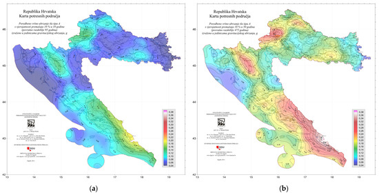
Figure 11.
Seismic hazard map of the Republic of Croatia showing comparative peak ground acceleration of type A with a probability of exceeding (a) 10% in 10 years (95 years return period); (b) 10% in 50 years (475 years return period), expressed in the units of gravitational acceleration g [48].
4.2. Gravity Load Analysis
The compressive stress limit is evaluated following the Eurocode guidelines using two design gravity load combinations [49]. To identify vulnerable zones, structural components prone to compressive stress concentration are investigated in detail. Load combination (LC1) evaluates the structure under unfavorable permanent loads while the load combination (LC2) considers unfavorable variable actions arising from the superimposed floor loads. The tensile (ft,CF = 0.30 MPa) and compressive (fc,CF = 5.1 MPa) elastic stress limits of the masonry material are calculated for a confidence factor (CF) equal to 1.35 and corresponding to the limited knowledge level (KL1). The assignment of limited knowledge class is based on the non-availability of in situ material characteristics. Except for a few internal walls, the stress concentration at the base of the building is well under the compressive elastic stress limit indicating adequate compressive strength against crushing failure (indicated in Figure 12).
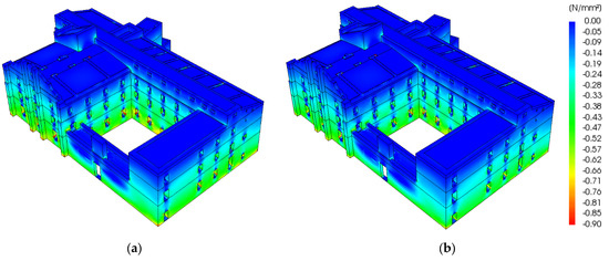
Figure 12.
Vertical stresses due to the gravity load combinations applied following the code requirements: (a) Load combination LC1; (b) Load combination LC2.
4.3. Lateral Load Analysis
The seismic action is defined according to the Eurocode 8 guidelines for the assessment and retrofitting of buildings using the nationally defined reference peak ground acceleration (agR) established for a return period of 475 years [50,51]. Recent studies describe the site conditions of the Old City of Dubrovnik as cretaceous dolomitic limestone and quaternary clay, with sand sediments of up to 5 m thickness, classifying the site as soil type A with an agR of 2.94 m/s2 at the northern and southern bedrock ridge [52,53] and superficial deposits of approximately 20–25 m depth central-filled and flattened part (former sea embayment), i.e., soil class B [41,49]. The case study building is classified with an importance class of III and has an importance factor equal to 1.2. The load combination (LC3) refers to the seismic load applied mainly in the NS direction and considering a factored EW component (and vice versa in the case of LC4 acting mainly in the EW direction). Both load combinations consider accidental torsional effects according to the code requirements. The choice of analysis method (i.e., response spectrum analysis) is mainly influenced by the complex geometry and irregularity, leading to a multitude of local and global vibrational modes (see Figure 8). Nonetheless, the uncertainties introduced due to the simplified assumptions of linearity and damping, integral to response spectrum analysis, cannot accurately represent the complex features and nonlinear behavior of historical structures. Consequently, this research presents an initial assessment based on the available and accessible information/data given the absence of detailed nonlinear characteristics typically associated with historical masonry construction.
The tensile stresses are shown in Figure 13 where the legend is bounded such that the red color represents the regions where maximum tensile stress exceeds the elastic stress limit and cracking is expected to occur. In the case of LC3, high tensile stresses are observed around the corners of the opening and near the wall–floor connections in the west wing. In the case of LC4, parts of the front façade show considerable tensile stresses due to out-of-plane deformations, especially in the upper portions of the wall where the cantilever motion is not restricted (gable wall). Wall segments in the west façade show relatively smaller stresses in comparison to the east façade because of the fewer openings and torsional motion caused by the irregularity of the building in-plan. The sway motion of the west- and east-wing façade causes stress concentration at the reentrant corners. An evaluation corresponding to the seismic action level corresponding to the different seismic zones in Croatia shows that the tensile stresses stay below the elastic tensile limit until the peak ground acceleration (agR) is 0.10 g. However, the capacity is exceeded for agR equal to 0.20 g in localized regions, such as openings and critical corners identified from the modal analysis.
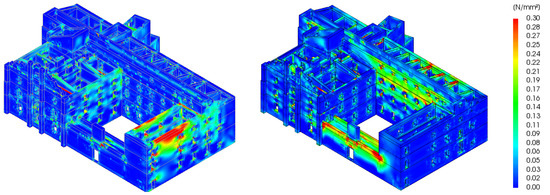
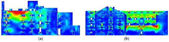
Figure 13.
Tensile stresses in the walls resulting from the seismic load combinations: (a) Load combination LC3; (b) Load combination LC4.
High tensile stresses are also observed in the masonry vaults near the wall connections and along the longitudinal direction of the vault in the east-wing hallway (see Figure 14). The development of stress follows along the length of the cross vault in the hallway of the south wing. The same response is observed at the entrance of the north wing and additionally in localized regions along the entire length of the vault, preventing the lateral walls to bend separately out-of-plane. Higher stresses are generated when the vault is oriented perpendicular to the direction of the seismic forces. Tensile stresses also develop in the vaults of the north wing near the connection with the east- and west-wing façade due to the tensile force generated by the east- and west-wing façades when the earthquake occurs in the EW direction. In general, the orientation of the barrel vault with respect to the seismic action plays a crucial role in the overall resistance where low-stress concentration is observed except for the sides which are relatively weaker due to the relatively smaller thickness.
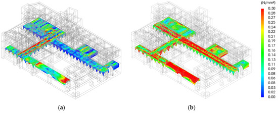
Figure 14.
Tensile stresses in the vaults resulting from the seismic load combinations: (a) Load combination LC3; (b) Load combination LC4.
In-plane shear stresses for the seismic load combinations are shown in Figure 15. In the case of LC3, concentrated diagonal shear stresses are observed between adjacent openings of the front façade and at the corners of the north-wing walls. The front and back façade of the south wing also indicate shear stresses with diagonal trajectories concentrated in the wall sections between adjacent openings. Similar results are obtained for the stresses originating from LC4, with the particularity that the stresses are higher at the walls of the east wing because of comparatively higher mass leading to the concentration of seismic forces.
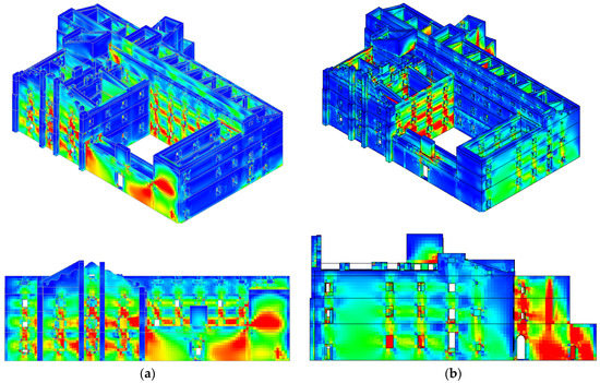
Figure 15.
In-plane shear stresses resulting from the seismic load combinations: (a) Load combination LC3; (b) Load combination LC4.
In unreinforced masonry buildings, the failure under seismic action typically occurs in the form of out-of-plane bending of the walls well before the in-plane strength is reached. In the case of cultural heritage buildings, this is likely because the construction in older times was often articulated in several years and the interventions were carried out by unskilled laborers [54,55,56]. Consequently, global assessment is not usually sufficient and additional verifications must be conducted to ensure safety against local collapse. The local assessment is highly dependent on the choice of a deformation mechanism whose boundary conditions are usually unknown [57]. The choice of failure mechanism is mostly based on the analytical modal response and is dependent on the tensile stress distribution within localized vulnerable areas. The principle of virtual work is applied to determine the horizontal load multiplier () which leads to the activation of the local damage mechanism [58].
where is the self-weight, is the thickness, is the lateral load transferred to the wall by the vaults/floor system, is the height, represents the axial load, and is the moment arm of the axial load along the thickness of the wall.
The analysis with a linear kinematic approach can be used to verify the damage limit state (DLS) and ultimate limit state (ULS). In the case of local mechanisms, the damage limit state corresponds to the onset of cracking which does not affect the entire structure but only a part of it. The horizontal load multiplier must be transformed into spectral acceleration ( for limit state verification [59].
where is the peak ground acceleration corresponding to the rock soil classification, is the soil factor, is the mass participation ratio, refers to the acceleration due to gravity, is the total height of the wall above the base of the building, and is the height of the center of gravity of the macro-block from the base of the building.
The clock tower situated at the entrance of the building as well as the free-standing gable wall located at the top of the front façade, exhibit considerable deformations even when subjected to low frequencies, making them particularly vulnerable to out-of-plane bending (see Figure 16a). Geometrical characteristics of the macro-element involved in the overturning are defined using the unsupported height and by assuming no connection to the orthogonal walls (see Figure 16b). The Croatian National Annex to Eurocode 8 requires the verification of damage limitation and ultimate limit states with a peak ground acceleration equal to 0.301 g and 0.156 g, respectively [50].
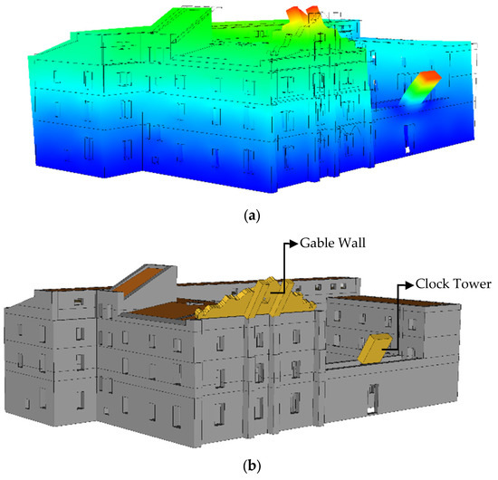
Figure 16.
Out-of-plane failure mechanism: (a) Identification of vulnerable areas using modal analysis; (b) Kinematic block of the gable wall and clock tower.
In the case of the clock tower with a height of 4.95 m, the relatively low value of the horizontal load multiplier indicates that a peak ground acceleration of 0.05 g is sufficient to activate the local mechanism, rendering the wall vulnerable to excessive deformations/bending. The local mechanism is activated at a slightly higher peak ground acceleration of 0.09 g in the case of the gable wall with a height of 6.18 m. The non-compliance corresponding to both limit states indicates high vulnerability even at low peak ground acceleration levels (see Table 5).
Table 5.
Verification of the damage limitation and ultimate limit states corresponding to the probable local mechanism.
5. Results and Conclusions
The presented research results highlight the necessity of a comprehensive approach/framework for the assessment of historical architecture that is not only valid for earthquakes but can be adapted to other natural hazards. It further highlights the applicability of FEM in combination with response spectrum analysis as a reliable starting point for such comprehensive assessment studies and the derivation of proper strengthening solutions. The challenges towards data collection and the trustworthiness of the results are highlighted.
The frequencies identified from ambient vibration measurements in both horizontal directions, i.e., NS and EW, are employed for the calibration of a finite element model created using elastic isotropic material properties, solids, shells, and trusses. Particular attention is paid to the modeling and meshing of the vaults and vault–wall connections. Due to the irregularity and complex dynamic behavior of the Jesuit College, a total of 250 mode shapes are required to ensure a mass participation of approximately 90% within the seismic analysis.
The numerical results indicate numerous wall segments in the building that experience stresses higher than the elastic tensile limit of 0.30 MPa. Critical zones with high tensile stresses due to the out-of-plane bending of the walls are identified to provide recommendations for strengthening and retrofitting. These include the facade walls of the west wing, the north façade of the south wing where there is an intersection with the east and west wings, the base of the clock tower, the piers between adjacent wall openings, the walls of the hallway in the south wing, the south-wing facade, and the west-wing façade. Out-of-plane bending is observed at the west- and south-wing walls. The out-of-plane bending is primarily attributed to the absence of moment stabilizing elements, flexible diaphragms, and the minimal torsional effects caused by inherent eccentricity. The wall sections between adjacent openings are prone to shear stress concentration due to the relatively small slenderness ratios (see Figure 15, indicated by red colors).
The floor system is supported by stone masonry vaults representing one of the most important structural and architectural features of the building, distributing lateral loads and the minimal torsional effects to the adjacent walls as shear forces. The complex geometry of the vaults is formed by multiple arch assemblies enchained together into a continuous surface. The analysis indicates the principal tensile stresses, which are higher than the material tensile stress limit in some parts of the structure in the case of a peak ground acceleration higher than 2.94 m/s2 (i.e., in the hallway cross vaults oriented perpendicularly to the main direction of the seismic action between the vault and the lateral walls, see Figure 14; at the long walls that lack the transverse-resistant elements to prevent the out-of-plane movement, see Figure 15).
Based on the results presented in this study, the overall seismic response of the building needs to be improved to ensure limited damage in case of future earthquakes. The strengthening of wooden diaphragms will allow a better redistribution of the seismic forces to the structural walls, restrict the out-of-plane bending, and dissipate more energy at the same time. Furthermore, cantilever walls, such as the clock tower and the gable wall, should be braced and/or tied to restrict lateral deformations and provide high resistance against lateral loads. Fiber-reinforced polymer (FRP) can be a suitable retrofitting option for the piers to provide high strength and ductility in the case of minor deformations. The initial strength state of the wall can be restored by grouting or epoxy injections requiring minimal intervention in compliance with the conservation principles.
A minor limitation of the current study is the assumption regarding the tensile force of the already installed iron tie-rods in the building that contribute to the building’s overall resistance to lateral forces by counteracting the out-of-plane bending of the walls. Some future developments of the current study can be related to the following aspects: (i) Experimental determination of the actual tensile forces in the tie-rods; (ii) Detailed investigation of the masonry and timber material characteristics using non-destructive techniques; (iii) Detailed chronological investigation of the documented damages and incorporation of the retrofitting measures in the numerical model; (iv) Enhanced analytical evaluation of the case study in its present state, incorporating the application of the non-linear finite element method (FEM) in conjunction with the gained knowledge level acquired from the present study; (v) Numerical implementation of possible strengthening measures to determine optimal conservation measures.
Author Contributions
Conceptualization, L.A., A.U., A.V. and D.P.; methodology, A.U. and L.A.; software, A.U.; validation, A.U., L.A. and D.P.; formal analysis, A.U.; investigation, A.U., A.V. and D.P.; resources, D.P. and A.V.; data curation, D.P., A.V. and L.A.; writing—original draft preparation, A.U., A.V. and D.P.; writing—review and editing, L.A.; visualization, A.U.; supervision, D.P. and L.A.; project administration, D.P.; funding acquisition, D.P. and L.A. All authors have read and agreed to the published version of the manuscript.
Funding
This research was funded by CROATIAN SCIENCE FOUNDATION, grant number HRZZ-IP-2020-02-3531.
Data Availability Statement
The data are not publicly available as the institution, specifically the Diocese of Dubrovnik, has granted permission to access the data exclusively through formal requests, limited to pre-approved individuals and specific purposes.
Acknowledgments
We are grateful to Davor Stanko and Jakov Uglešić for providing technical support during the field measurements which helped us collect accurate data. We would also like to express our sincere gratitude to the Institute for the Restoration of Dubrovnik and the Diocese of Dubrovnik for their invaluable support and contribution in addressing the challenges related to acquiring data on the “UNESCO World Heritage List” cultural heritage buildings. We are also thankful to Snježana Markušić for her valuable input and critical evaluation of our seismicity section. We would also like to convey our profound appreciation for the visual resources provided by the Institute of Art History which have significantly enhanced the depth and quality of our investigation into the subject matter.
Conflicts of Interest
The authors declare no conflict of interest. The funders had no role in the design of the study; in the collection, analyses, or interpretation of data; in the writing of the manuscript; or in the decision to publish the results.
References
- Lourenço, P.B. Conservation of cultural heritage buildings: Methodology and application to case studies. Rev. ALCONPAT 2013, 3, 98–110. [Google Scholar] [CrossRef]
- Lourenco, P.; Karanikoloudis, G. Seismic behavior and assessment of masonry heritage structures. Needs in engineering judgement and education. RILEM Tech. Lett. 2018, 3, 114–120. [Google Scholar] [CrossRef]
- Wenk, T.; Beyer, K. Seismic conservation strategies for cultural heritage buildings in Switzerland. In Proceedings of the 2nd European Conference on Earthquake Engineering and Seismology 2014 (2nd ECEES), Istanbul, Turkey, 25–29 August 2014. [Google Scholar]
- Barbieri, G.; Valente, M.; Biolzi, L.; Togliani, C.; Fregonese, L.; Stanga, G. An insight in the late Baroque architecture: An integrated approach for a unique Bibiena church. J. Cult. Herit. 2017, 23, 58–67. [Google Scholar] [CrossRef]
- Dall’Asta, A.; Leoni, G.; Meschini, A.; Petrucci, E.; Zona, A. Integrated approach for seismic vulnerability analysis of historic massive defensive structures. J. Cult. Herit. 2019, 35, 86–98. [Google Scholar] [CrossRef]
- Altunişik, A.C.; Okur, F.Y.; Genç, A.F.; Günaydin, M.; Adanur, S. Automated Model Updating of Historical Masonry Structures Based on Ambient Vibration Measurements. J. Perform. Constr. Facil. 2018, 32, 4017126. [Google Scholar] [CrossRef]
- Kujawa, M.; Lubowiecka, I.; Szymczak, C. Finite element modelling of a historic church structure in the context of a masonry damage analysis. Eng. Fail. Anal. 2020, 107, 104233. [Google Scholar] [CrossRef]
- Betti, M.; Galano, L.; Vignoli, A. Finite Element Modelling for Seismic Assessment of Historic Masonry Buildings. In Earthquakes and Their Impact on Society; Springer: Cham, Switzerland, 2016; pp. 377–415. [Google Scholar]
- Altunisik, A.C.; Karahasan, O.S.; Okur, F.Y.; Kalkan, E.; Ozgan, K. Finite Element Model Updating and Dynamic Analysis of a Restored Historical Timber Mosque Based on Ambient Vibration Tests; ASTM International: West Conshohocken, PA, USA, 2019. [Google Scholar]
- Lourenço, P.B. Computations on historic masonry structures. Prog. Struct. Eng. Mater. 2002, 4, 301–319. [Google Scholar] [CrossRef]
- Roca, P.; Cervera, M.; Gariup, G.; Pela’, L. Structural Analysis of Masonry Historical Constructions. Classical and Advanced Approaches. Arch. Comput. Methods Eng. 2010, 17, 299–325. [Google Scholar] [CrossRef]
- Valente, M. Seismic vulnerability assessment and earthquake response of slender historical masonry bell towers in South-East Lombardia. Eng. Fail. Anal. 2021, 129, 105656. [Google Scholar] [CrossRef]
- Salachoris, G.P.; Standoli, G.; Betti, M.; Milani, G.; Clementi, F. Evolutionary numerical model for cultural heritage structures via genetic algorithms: A case study in central Italy. Bull. Earthq. Eng. 2023, 1–35. [Google Scholar] [CrossRef]
- Tomaszewska, A.; Szymczak, C. Identification of the Vistula Mounting tower model using measured modal data. Eng. Struct. 2012, 42, 342–348. [Google Scholar] [CrossRef]
- Ramos, L.F.; Alaboz, M.; Aguilar, R.; Lourenço, P.B. Dynamic Identification and FE Updating of S. Torcato Church, Portugal. In Dynamics of Civil Structures; Springer: New York, NY, USA, 2011; Volume 4, pp. 71–80. [Google Scholar]
- Torres, W.; Almazán, J.L.; Sandoval, C.; Boroschek, R. Operational modal analysis and FE model updating of the Metropolitan Cathedral of Santiago, Chile. Eng. Struct. 2017, 143, 169–188. [Google Scholar] [CrossRef]
- Ceravolo, R.; Pistone, G.; Fragonara, L.Z.; Massetto, S.; Abbiati, G. Vibration-Based Monitoring and Diagnosis of Cultural Heritage: A Methodological Discussion in Three Examples. Int. J. Archit. Herit. 2016, 10, 375–395. [Google Scholar] [CrossRef]
- Ereiz, S.; Duvnjak, I.; Fernando Jiménez-Alonso, J. Review of finite element model updating methods for structural applications. Structures 2022, 41, 684–723. [Google Scholar] [CrossRef]
- Standoli, G.; Salachoris, G.P.; Masciotta, M.G.; Clementi, F. Modal-based FE model updating via genetic algorithms: Exploiting artificial intelligence to build realistic numerical models of historical structures. Constr. Build. Mater. 2021, 303, 124393. [Google Scholar] [CrossRef]
- Bianconi, F.; Salachoris, G.P.; Clementi, F.; Lenci, S. A Genetic Algorithm Procedure for the Automatic Updating of FEM Based on Ambient Vibration Tests. Sensors 2020, 20, 3315. [Google Scholar] [CrossRef]
- Uzair, A.; Abrahamczyk, L.; Gómez, D.; Elias, K.; Vrban, A.; Penava, D.; Markušić, S. Earthquake Performance of a Cultural Heritage Building: The Jesuit College in Dubrovnik, Croatia. In Proceedings of the 2nd Croatian Conference on Earthquake Engineering—2CroCEE, Zagreb, Croatia, 22–24 March 2023; pp. 394–405. [Google Scholar]
- Penava, D.; Vrban, A.; Uglešić, J.; Stanko, D.; Markušić, S. Episcopal seminary building and classical gymnasium (Jesuit college) in Dubrovnik construction 1662–1765 in terms of contemporary earthquake resistant design supported by measurements. In Proceedings of the 10th International Congress of Croatian Society of Mechanics, Pula, Croatia, 28–30 September 2022; Skozrit, I., Tonković, Z., Sorić, J., Eds.; Croatian Society of Mechanics: Pula, Croatia, 2022; pp. 39–40. [Google Scholar]
- Horvat-Levaj, K. Baroque Architecture (in Original: Barokna Arhitektura). Series: History of Art in Croatia (in Original: Serija Povijest Umjetnosti u Hrvatskoj); Naklada: Ljevak, Zagreb, 2015; pp. 138–140, 157–165, 520–525. ISBN 978-9-53303-858-2. [Google Scholar]
- Grünthal, G.; Musson, R.; Schwarz, J.; Stucchi, M. European Macroseismic Scale 1998, 15th ed.; Cahiers du Centre Européen de Géodynamique et de Séismologie: Luxembourg, 1998. [Google Scholar]
- Morić, D. Floor Structures and Seismic Resistance of Cultural Heritage Stone Masonry Buildings; Josip Juraj Strossmayer University of Osijek Faculty of Civil Engineering Osijek: Osijek, Croatia, 2003; ISBN 9-53-696205-5. [Google Scholar]
- EN 1998–1:2004; Eurocode 8: Design of Structures for Earthquake Resistance—Part 1: General Rules, Seismic Actions and Rules for Buildings. European Committee for Standardization: Brussels, Belgium, 2004.
- Calderini, C.; Lagomarsino, S. Seismic Response of Masonry Arches Reinforced by Tie-Rods: Static Tests on a Scale Model. J. Struct. Eng. 2015, 141, 4014137. [Google Scholar] [CrossRef]
- WordPress. Seismic Risk Assessment of Cultural Heritage Buildings in Croatia-SeisRICHerCRO. Croatian Science Foundation Research (HrZZ), Project IP-2020-02-3531. 2021. Available online: https://seisrichercro.wordpress.com/ (accessed on 17 March 2023).
- DIANA, Diana; DIANA FEA, B.V.: Delft, The Netherlands, 2017.
- Compán, V.; Pachón, P.; Cámara, M.; Lourenço, P.B.; Sáez, A. Structural safety assessment of geometrically complex masonry vaults by non-linear analysis. The Chapel of the Würzburg Residence (Germany). Eng. Struct. 2017, 140, 1–13. [Google Scholar] [CrossRef]
- Radnić, J.; Matešan, D.; Abaza, A. Restoration and Strengthening of Historical Buildings: The Example of Minceta Fortress in Dubrovnik. Adv. Civ. Eng. 2020, 2020, 8854397. [Google Scholar] [CrossRef]
- Araujo, A.S.; Lourenco, P.B.; Oliveira, D.V.; Leite, J. Seismic Assessment of St James Church by Means of Pushover Analysis—Before and After the New Zealand Earthquake. Open Civ. Eng. J. 2012, 6, 160–172. [Google Scholar] [CrossRef]
- Mustafaraj, E.; Luga, E.; Corradi, M.; Borri, A.; Muceku, Y.; Zharkalli, A. Physical-Mechanical Properties of Stone Masonry of Gjirokastër, Albania. Materials 2021, 14, 1127. [Google Scholar] [CrossRef] [PubMed]
- Beconcini, M.L.; Croce, P.; Formichi, P.; Landi, F.; Puccini, B. Experimental Evaluation of Shear Behavior of Stone Masonry Wall. Materials 2021, 14, 2313. [Google Scholar] [CrossRef] [PubMed]
- Diaferio, M.; Foti, D.; Giannoccaro, N.I.; Ivorra, S. Optimal model through identified frequencies of a masonry building structure with wooden floors. Int. J. Mech. 2014, 8, 282–288. [Google Scholar]
- Mirra, M.; Ravenshorst, G. Optimizing Seismic Capacity of Existing Masonry Buildings by Retrofitting Timber Floors: Wood-Based Solutions as a Dissipative Alternative to Rigid Concrete Diaphragms. Buildings 2021, 11, 604. [Google Scholar] [CrossRef]
- Asteris, P.G.; Sarhosis, V.; Mohebkhah, A.; Plevris, V.; Papaloizou, L.; Komodromos, P.; Lemos, J.V. Numerical Modeling of Historic Masonry Structures. In Handbook of Research on Seismic Assessment and Rehabilitation of Historic Structures; IGI Global: Hershey, PA, USA, 2015; pp. 213–256. [Google Scholar]
- HRN EN 1990:2011/NA:2011; Eurocode: Basis of Structural Design-National Annex. European Committee for Standardization: Brussels, Belgium, 2011.
- Amabili, M.; Carra, S.; Collini, L.; Garziera, R.; Panno, A. Estimation of tensile force in tie-rods using a frequency-based identification method. J. Sound Vib. 2010, 329, 2057–2067. [Google Scholar] [CrossRef]
- Lagomarsino, S.; Calderini, C. The dynamical identification of the tensile force in ancient tie-rods. Eng. Struct. 2005, 27, 846–856. [Google Scholar] [CrossRef]
- Stanko, D.; Korbar, T.; Markušić, S. Evaluation of the local site effects and their implication to the seismic risk of the UNESCO World Heritage Site Old City of Dubrovnik (Croatia). J. Earthq. Eng. 2023. [Google Scholar] [CrossRef]
- Old City of Dubrovnik-UNESCO World Heritage Centre. Available online: https://whc.unesco.org/en/list/95/ (accessed on 29 May 2023).
- Herak, M.; Herak, D.; Markušić, S. Revision of the earthquake catalogue and seismicity of Croatia, 1908–1992. Terra Nova 1996, 8, 86–94. [Google Scholar] [CrossRef]
- Jemo, I.; Brigović, N. The Restoration of Dubrovnik. The Catalogue of Works in the Historic Centre of Dubrovnik from 1979 till 2009.
- Markušić, S.; Ivančić, I.; Sović, I. The 1667 Dubrovnik earthquake—Some new insights. Stud. Geophys. Geod. 2017, 61, 587–600. [Google Scholar] [CrossRef]
- Knežević, S. The Restoration of Dubrovnik 1979–1989. (in Croatian: Obnova Dubrovnika 1979–1989); Zavod za Obnovu Dubrovnika: Dubrovnik, Croatia, 1989. [Google Scholar]
- Herak, M.; Allegretti, I.; Herak, D.; Kuk, K.; Kuk, V.; Marić, K.; Markušić, S.; Stipčević, J. HVSR of ambient noise in Ston (Croatia): Comparison with theoretical spectra and with the damage distribution after the 1996 Ston-Slano earthquake. Bull. Earthq. Eng. 2010, 8, 483–499. [Google Scholar] [CrossRef]
- Herak, M.; Allegretti, I.; Herak, D.; Ivančić, I.; Kuk, V.; Marić, K.; Markušić, S.; Sović, I. Earthquake Hazard Maps of Republic of Croatia (in Croatian: Karte Potresnih Područja Republike Hrvatske). 2011. Available online: http://seizkarta.gfz.hr/karta.php (accessed on 5 February 2021).
- EN 1990:2002+A1:2005+A1:2005/AC:2010; Eurocode: Basis of Structural Design. European Committee for Standardization: Brussels, Belgium, 2010.
- EN 1998-1:2004+AC:2009; Eurokod 8: Projektiranje Potresne Otpornosti Konstrukcija—1. dio: Opća Pravila, Potresna Djelovanja i Pravila za Zgrade. European Committee for Standardization: Brussels, Belgium, 2009.
- EN 1998-3:2005+AC:2010; Eurokod 8: Projektiranje Potresne Otpornosti Konstrukcija—3. dio: Ocjenjivanje i Obnova Zgrada. European Committee for Standardization: Brussels, Belgium, 2010.
- Ivančić, I.; Herak, D.; Herak, M.; Allegretti, I.; Fiket, T.; Kuk, K.; Markušić, S.; Prevolnik, S.; Sović, I.; Dasović, I.; et al. Seismicity of Croatia in the period 2006–2015. Geofizika 2018, 35, 69–98. [Google Scholar] [CrossRef]
- Markušić, S.; Stanko, D.; Korbar, T.; Sović, I. Estimation of near-surface attenuation in the tectonically complex contact area of the northwestern External Dinarides and the Adriatic foreland. Nat. Hazards Earth Syst. Sci. 2019, 19, 2701–2714. [Google Scholar] [CrossRef]
- de Felice, G. Out-of-Plane Seismic Capacity of Masonry Depending on Wall Section Morphology. Int. J. Archit. Herit. 2011, 5, 466–482. [Google Scholar] [CrossRef]
- Misir, I.S.; Yucel, G.; Kuran, F.; Eser, C.B.; Aldemir, O.; Topcu, S. Experimental out-of-plane damage limits of historical stone masonry walls. Constr. Build. Mater. 2022, 333, 127098. [Google Scholar] [CrossRef]
- Giuffrè, A.; Carocci, C.; Baggio, C.; Gruppo Nazionale Difesa dai Terremoti. Syracuse. In Assessorato Alla Cultura. Sicurezza e Conservazione dei Centri Storici: Il Caso Ortigia: Codice di Pratica per Gli Interventi Antisismici Nel Centro Storico; Laterza: Bari, Italy, 1993; ISBN 978-8-84204-250-1. [Google Scholar]
- Zuccaro, G.; Dato, F.; Cacace, F.; de Gregorio, D.; Sessa, S. Seismic collapse mechanisms analyses and masonry structures typologies: A possible correlation. Ing. Sismica 2017, 34, 121–149. [Google Scholar]
- NTC 2018. Decreto Ministeriale 14 Gennaio 2018, Aggiornamento delle Norme Tecniche per Lecostruzioni, Supplemento Ordinario alla “Gazzetta Ufficiale, n. 42 del 20 Febbraio 2018-Serie Generale; Ministero delle Infrastrutture e dei Trasporti: Roma, Italy, 2018.
- OPCM 3274. Ordinanza del Presidente del Consiglio dei Ministri n. 3274. Primi Elementi in Materia di Criteri Generali per la Classificazione Sismica del Territorio Nazionale e di Normative Tecniche per le Costruzioni in Zona Sismica. 2003. Available online: https://www.bosettiegatti.eu/info/circolari/statali/2003_ord3274_sismica.htm (accessed on 3 January 2023).


Disclaimer/Publisher’s Note: The statements, opinions and data contained in all publications are solely those of the individual author(s) and contributor(s) and not of MDPI and/or the editor(s). MDPI and/or the editor(s) disclaim responsibility for any injury to people or property resulting from any ideas, methods, instructions or products referred to in the content. |
© 2023 by the authors. Licensee MDPI, Basel, Switzerland. This article is an open access article distributed under the terms and conditions of the Creative Commons Attribution (CC BY) license (https://creativecommons.org/licenses/by/4.0/).