Review

A Review on Behavior and Fatigue Performance of Orthotropic Steel–UHPC Composite Deck

1
Department of Civil and Environmental Engineering, Shantou University, Shantou 515063, China
2
College of Civil and Architecture Engineering, Shaoyang University, Shaoyang 422000, China
*
Author to whom correspondence should be addressed.
Buildings 2023, 13(8), 1906; https://doi.org/10.3390/buildings13081906
Submission received: 5 June 2023 / Revised: 21 July 2023 / Accepted: 23 July 2023 / Published: 26 July 2023
(This article belongs to the Special Issue Brittle Behaviour of High-Performance Concrete Structures)

Abstract

:
Although orthotropic steel decks (OSDs) have been widely used in the construction of long-span bridges, there are frequently reported fatigue cracks after years of operation, and the bridge deck overlay also presents severe damage due to OSD crack-induced stiffness reduction. Ultra-high performance concrete (UHPC), recognized as the most innovative cementitious composites and the next generation of high-performance materials, shows high strength, ductility, toughness, and good performance on durability. After its first application to the OSD bridge in the early 2000s, the orthotropic steel–UHPC composite deck has been comprehensively studied worldwide. This review will summarize some important studies and findings on the behavior and fatigue performance of the orthotropic steel–UHPC composite deck. The existing studies and engineering applications indicate that such a deck system presents good bending behavior and high fatigue performance. The failure mode of shear studs in the UHPC layer is dominated by shear fractures. The cracking of the UHPC layer shall consider the superposition effect of stress from both the whole bridge structure and local decks. While some reasonable structural details in the traditional OSD may not work for the orthotropic steel–UHPC composite deck, this paper has shown that the steel–UHPC composite deck has excellent performance in bearing capacity, stiffness, and fatigue resistance. However, the fatigue performance of the steel–UHPC composite deck and its evaluation method still need validation from engineering applications. It is recommended to evaluate the stress behavior and structural parameters, as well as fatigue life by conducting the field test under in-service traffic conditions.

1. Introduction

For bridge engineering applications, the fundamental function of the bridge deck is to directly bear, distribute, and transfer the wheel loads. The bridge deck may also react as part of the main girder to bear force acting on the bridge superstructure. Highway bridges normally adopt three types of bridge decks, namely the concrete deck, steel deck, and steel–concrete composite deck [1]. It is well known that under the action of wheel loads, the concrete decks produce small deformation due to the high stiffness of the deck system. However, its heavy dead load and low tensile strength of concrete limit its application in bridge engineering. The steel bridge deck is usually made of an orthotropic steel deck (OSD), which has light weight, high bearing capacity, and significant overloading capacity. However, this type of deck system can produce large deformation under wheel load due to its low structural stiffness. As a result, fatigue cracking and pavement damage are frequently reported after years of operation. The steel–concrete composite deck includes several types of structures, such as the orthotropic steel–concrete composite deck, the orthotropic steel–steel fiber reinforced concrete composite deck, and the orthotropic steel ultra-high performance concrete (steel–UHPC) composite deck. The first two can only be applicable to medium and small-span bridges because of the large thickness overlay and its significantly increased dead loads. They may also be prone to cracks under concentrated wheel loading due to the low tensile strength of concrete. With the development of the UHPC, the orthotropic steel–UHPC composite deck is widely used in various types of bridge structures with different span lengths, especially in long-span bridges.
The OSD, consisting of the deck plate, respectively, stiffened by the floorbeam and the ribs in bridge transverse and longitudinal directions, presents different structural properties in two orthogonal directions. The OSD was first used in Germany as the bridge deck to build the steel bridge. After the Second World War, the growing demand for post-war traffic recovery made OSDs widely used in bridge engineering [2]. Since the Severn Bridge in the UK adopted the OSD steel box girder for the first time, the OSD has become the most popular deck system for long-span bridges. Figure 1 shows two structural forms consisting of open ribs or closed ribs, with the traditional pavement on the deck plate.
The OSD has been widely used in long-span suspension bridges and cable-stayed bridges due to its remarkable advantages, but the OSD is not a perfect structure since there are many welds in the orthotropic steel bridge deck, which have small defects. Under the cyclic loading of the vehicle, the defects lead to the emergence of fatigue cracks. With the extent of the fatigue cracks, the cross-section weakens significantly and the stress concentration is severe [3,4,5]. Fatigue cracking is frequently reported on bridges, particularly for those with large traffic volumes and serious overloading trucks, the typical locations of fatigue cracking are shown in Figure 2 [6]. The fatigue cracking may also lead to frequent maintenance and replacement of bridge deck pavement, which presents a great impact on local traffic. Therefore, avoiding fatigue cracking and pavement damage is one of the major long-term considerations in the bridge engineering community.
With the growing increase in bridge main span and the rapid increase in traffic volume, fatigue cracking of the OSD becomes a severe challenge in bridge engineering. Hence, many scholars have conducted extensive research on this topic, including laboratory model tests, FEM analyses, and field tests. Wang [7] conducted full-scale fatigue tests on the OSD of a cable-stayed bridge, and found that the impact of welding residual stress on the fatigue life of structural details in the compressive stress zone cannot be ignored. Zhang’s [8] research shows that there are significant differences in the fatigue of vulnerable parts of OSDs, and the stress distribution in the vicinity of fatigue cracks constantly changes as the cracks propagate. Zweraeman [9] believes that the small stress amplitude generated by high-order vibration of steel bridges under random traffic flow, which is lower than the fatigue cutoff limit, can also cause fatigue damage to the steel bridge. Connor [10,11] conducted controlled loading tests and random vehicle flow tests on two different bridges, and studied the effect of out-of-plane deformation on the fatigue life of the diaphragm based on on-site test data.
The deck of a steel bridge faces the challenges of orthotropic deck cracking and easy damage to the pavement layer, which conventional techniques cannot fundamentally solve [12]. Only by relying on breakthroughs in materials and developing corresponding new structural systems can we find effective solutions to the difficult problems in traditional steel bridges and steel–concrete composite bridges. Compared with traditional orthotropic bridge decks, the steel–UPHC composite bridge structure has the following two characteristics: Firstly, it can significantly improve the stiffness of the bridge deck. Secondly, the synergistic effect of the UHPC layer and orthotropic steel plate can significantly reduce the fatigue stress amplitude in the orthotropic plate under local wheel loads. The steel–UHPC composite bridge structure is in its initial stage of practical application, and its superior performance needs to be known and accepted through a process. Therefore, summarizing existing literature and analyzing the characteristics of static, shear, and fatigue performance of composite structures under different conditions have important guiding significance for subsequent theoretical research, experimental development, and engineering applications of this structure.
Mechanical properties and fatigue problems have always been difficult and hot issues that must be faced in the development of orthotropic bridge deck structures and even the entire steel structure field. This paper summarizes the literature on the mechanical and fatigue properties of orthotropic steel–UHPC composite deck structures, briefly compares and analyzes the mechanical properties of UHPC and normal concrete, briefly introduces the orthotropic steel–UHPC composite deck structures and related application cases, and focuses on the fatigue issues related to orthotropic steel–UHPC composite deck structures. Finally, the paper highlights the limitations of current research on this composite structure and explores the future directions of research in this field.

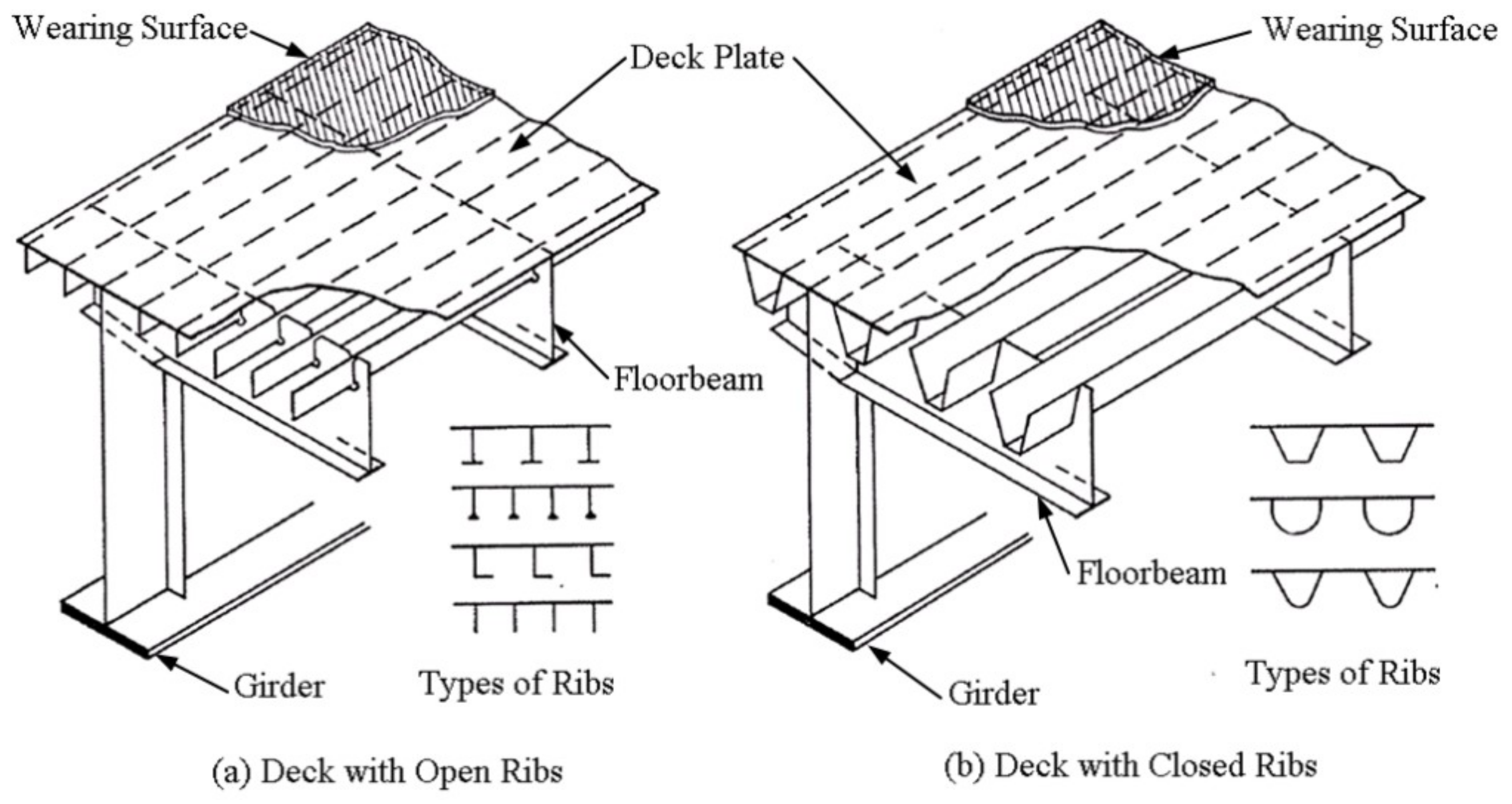
2. The Orthotropic Steel–UHPC Composite Deck

The UHPC is an innovative cement-based composite material, which was first developed by French scholars in 1993. The material consists of cement, silica fume, fine aggregate, fiber, water reducer and other materials, as shown in Figure 3 and is constructed according to the principle of maximum compactness [13,14]. The goal is to minimize the internal pores and micro-cracks of the material, so as to obtain excellent mechanical properties and durability.
Due to the use of fiber inside the UHPC, the tensile and deformation properties of concrete have greatly improved, and the compressive and flexural strength of UHPC can reach 3 times and 10 times that of normal concrete (NC), respectively, with its creep coefficient only about 5% of the NC. It is reported that its durability performance is significantly better than the NC. The mechanical properties and durability index of UHPC are greatly enhanced compared to NC, as shown in Table 1.
The emergence of UHPC materials has led to the development of structures towards economy and environmental protection. Firstly, the superior mechanical properties of UHPC have greatly reduced the weight of the structure while meeting the usage conditions. Secondly, UHPC can be prepared by replacing part of cement with Industrial waste fly ash and mineral powder. Thirdly, UHPC can be used for combining structures and repairing and strengthening existing structures. Zhao [15] compared and analyzed the steel UHPC composite beam and conventional steel plate composite beam schemes based on a certain overpass bridge project. The results showed that they had significant advantages in construction and durability, and the unit price of the main materials decreased by about 4.3% compared to conventional steel–concrete composite beams.
With the use of UHPC, it is expected to develop a more economical, environmentally friendly, stronger, and more durable high-performance structure. Based on the above advantages, UHPC became more and more popular worldwide, and its preparation, production, construction, and prefabrication technology have become mature in bridge engineering.
Table 1. UHPC and NC main mechanics and durability index.
Material TypeUHPCNCReferences
Compressive strength/MPa120~23030~60[16,17,18,19,20]
Flexural Strength/MPa15~602~5[16,17,18,19,20]
Elasticity modulus/GPa40~6030~40[18,19,20]
Creep coefficient0.2–0.3 (High temperature steam curing)1.4~2.5[18,19]
Diffusion coefficient of chloride ion/(m 2 /s)<0.02 × 10 11 >1 × 10 11 [16,18,20]
Electrical resistivity/(k Ω · cm)113396 (C80)[18]
The traditional OSD uses asphalt, resin, or composite paving materials, such as stone mastic asphalt (SMA), epoxy asphalt concrete (EAC), and epoxy resin asphalt. The elastic modulus of these pavements, formed by organic glue, is significantly lower compared to steel or concrete and decreases notably with the increase in temperature. When the temperature of the pavement is high or the sunshine is strong, the elastic modulus of the pavement decreases obviously. For example, in China’s southern area, like Guangdong Province, the weather is hot and solar radiation is strong. The observed highest temperature of the pavement can reach about 65 °C [21], and the elastic modulus of the pavement may only be a few hundred MPa, as shown in Figure 4. Therefore, the contribution of pavement to bridge deck stiffness is very small; thus, the stress at OSD details will be significantly increased under wheel loads, which may lead to fatigue cracking.
The orthotropic steel–UHPC composite deck consists of the shear connectors welded on the OSD deck plate, and the casted UHPC layer, as shown in Figure 5. In order to reduce the dead loads, the thickness of the UHPC layer is generally 35 mm to 60 mm. While in order to reduce the tensile stress in the thin UHPC layer, double-layer bidirectional (longitudinal and transverse) steel bars are arranged in the UHPC. Steam curing is usually used to reduce shrinkage in the process of curing. In addition, in order to improve the driving conditions on the bridge deck, the traditional 20–40 mm asphalt overlay will be paved on the UHPC. Figure 6 is the major construction process of orthotropic steel–UHPC composite deck.
Engineering application has recognized many advantages of the orthotropic steel–UHPC composite deck. The UHPC layer is cement-based material, which improves the performance of the upper asphalt pavement and can effectively reduce the debonding, cracking, and rutting of the asphalt pavement. Meanwhile, the steel–UHPC composite structure can improve the bridge deck stiffness and reduce the stress at details of the OSD under wheel load, hence greatly increasing the fatigue life of the bridge deck. The UHPC layer presents high tensile strength and high ductility, which can satisfy the demands of stress and deformation under wheel loads. In addition, the thin UHPC is light-weighted, which is helpful to reduce the seismic inertia force acting on the bridges and to facilitate larger-span crossing [22]. It is also found that the UHPC layer can be prefabricated together with the OSD, which is applicable for assembly construction to improve its quality control.

3. Engineering Application of Orthotropic Steel–UHPC Composite Deck

De Jong and Kolstein first proposed the combination of the UHPC and the OSD to repair existing steel bridge cracks [23]. They first removed the bridge deck pavement of the Dutch Garland Bridge (Caland Bridge) and replaced it with RHPC (reinforced high-performance concrete), as shown in Figure 7. Then, they carried out FEM and laboratory tests and found that the local bending stress was reduced by 80% on the deck plate side. Although they proposed the idea to reduce the fatigue stress of OSD, the steel and UHPC are not treated as a composite structure since the UHPC layer and steel panels worked together through a thin bonding layer between them, in which the composite action is weak and only the load distribution function of the UHPC layer could be considered.
In the subsequent years, the composite deck formed by steel and UHPC attracted many researchers and engineers. In 2007, the world’s first steel–UHPC composite bridge, the Gärtnerplatz Bridge, was built over the Fulda River in Germany [24]. In 2011, the overlay of a traditional OSD bridge built in 1970 was replaced in France by using UHPC material. A similar replacement on the Illzach Bridge in France [25] was carried out using precasted UHPC plates and wet connection joints.
The application of UHPC in bridge engineering in Asia was relatively late, but it developed rapidly over the past decade. Currently, more than one hundred UHPC bridges have been built in Asia, some of which are steel–UHPC composite structures. In China, Shao Xudong [26] first practiced the deck replacement of the Zhaoqing Mafang Bridge, by using the UHPC layer, as shown in Figure 8. The thickness of the cast-in-place UHPC layer was 50 mm and the thickness of the surface asphalt pavement was 30 mm. The UHPC layer and the steel panel are connected by way of “stud + epoxy resin adhesive”. Compared with the traditional epoxy pavement on other spans of the bridge, over 12 years of operation demonstrated that the composite deck system has obvious advantages.
In the following years, the steel–UHPC composite deck, in which the steel and UHPC layers work together through shear connections has been comprehensively studied, including its bending and shear behaviors and its fatigue performance. In the meantime, the steel–UHPC composite deck has been widely used as a new deck system in the construction of steel bridges. Table 2 shows newly built bridges using steel–UHPC composite deck in China, and Table 3 shows deck replacement using the steel–UHPC composite structure. It is clear that the orthotropic steel–UHPC composite deck is increasingly popular and is used by different types of bridge structures, i.e., not limited to long-span bridges. Figure 9 shows the orthotropic steel–UHPC composite decks under construction for four bridges.

4. Research History and Up-to-Date Progress

In order to meet the engineering requirement using the steel–UHPC composite deck, research studies have been carried out through laboratory tests, field tests, and FEM analysis to investigate its bending, shear, and slip resistance, as well as the fatigue performance of OSD and shear connectors [20,27,28,29,30,31,32,33,34,35,36,37,38,39].

4.1. Flexural Behaviors

4.1.1. Load against Deflection

The flexure behaviors of the steel–UHPC composite deck can be evaluated in many aspects, such as strain and stress, displacement, crack width, nominal cracking stress, failure mode, and ultimate load.
Through laboratory tests and FEM analysis, Li [40] found that the deck has a higher tensile strength in the bridge longitudinal direction than in the transverse direction. The steel–UHPC composite deck directly bears the local wheel load and then transfers the load in the longitudinal and transverse direction. When the wheel loads ride the U-rib laterally, as shown in Figure 10, the composite plate above the U-rib web bears a negative bending moment, and the produced moment is highly dependent on the location of the wheel center in the transverse direction.
For bending tests in the bridge transverse direction, Shao [28] carried out stripe model tests for the steel–UHPC composite deck. He found that under a positive moment, the load-displacement curve displayed four stages, i.e., the elastic, elastoplastic, crack propagating, and yielding stage. For the same fiber type and its volume percentage, the bending capacity increased with the percentage of reinforcement in the first stage, and the load-displacement curve was a straight line without cracking on the UHPC surface. While in the second stage, the maximum bearing capacity also increased with the increase in reinforcement and deviation of nonlinear displacement appeared due to crack initiation, indicating a decrease in structural stiffness. Crack propagation further decreased the structural stiffness and significant nonlinear features can be observed when multiple cracks appeared. In the yielding stage, the displacement in the span center increased rapidly, with rapidly increased crack width at almost the same number of cracks. It is highlighted that the thickness of the UHPC layer and reinforcement percentage have the greatest influence on the structural stiffness in the crack propagation stage. Zheng [29] pointed out that under the concentrated wheel loads, the composite deck presented significant local effects on stress, i.e., high stress only produced at the area directly underneath the wheel load, and local deck plate deformation produced notable higher stress than that produced by the overall panel deformation in bridge transverse direction.
Bending tests in the bridge longitudinal direction also showed three similar stages as that in the bridge transverse direction. In the elastic stage of steel–UHPC composite girder, cracks were not observed, and the curve of load against displacement was linear. At the crack propagation stage, although cracks appeared on the surface, structural stiffness did not show a significant decrease compared to the elastic stage. The reason is that the girder has high structural stiffness and the UHPC layer only contributes a small percentage to it. Even after the crack appeared, the UHPC layer still works well due to the small width of the crack and the bridging effect of steel fibers in the matrix. Therefore, the appeared cracks did not lower the structural stiffness of the steel–UHPC composite girder. Meanwhile, the load-midspan displacement and bearing capacity showed minor differences against different structural parameters. In the yielding stage, the longitudinal ribs yielded, leading to a rapid increase in displacement and loss of bearing capacity [41].

4.1.2. Stress Behavior

Dieng [42] investigated the effects of deck replacement using the steel–UHPC composite structure. They found that the local deflection decreased by 45% and the strain at the deck plate side and the rib wall side of the RD detail decreased by 60% and 30–50%, respectively. Kong [37] estimated the tensile and compressive stress in the UHPC layer, by using the stress superposition method based on a refined full-bridge FEM model and a hybrid full-bridge model, respectively. They found that the longitudinal compressive stress was much lower than the UHPC compressive strength even under the most critical loading condition. Li [43] compared the mechanics of the deck with the UHPC layer to that with an epoxy overlay. The decrease in maximum tensile stress, shear strain, and deflection could reach 54.8%, 78.9%, and 39.1%, respectively.
In the transverse bending test, the strain along the section height is measured on the steel–UHPC composite deck. When the load level is low, the cross-section strain is linearly distributed. With the increase in load, non-linearity gradually appears. For the reinforced steel–UHPC composite plate, nonlinear strain distribution along section height appeared at about 45% of the ultimate load, but it can be approximately considered that the strain distribution along the section height satisfied the plane section assumption. In the longitudinal bending test, the strain distribution along the section height is also linear when the load level is low. With the increase in load, non-linearity gradually appears. When the load is less than 76.7–86% of the ultimate load, the plane section assumption still holds. Since the overall stiffness of the composite deck is very large, even after the crack appears, the crack growth rate is low; hence, structural stiffness does not show an obvious decrease. Therefore, for steel–UHPC composite beams, the strain distribution along the section height is basically consistent with the plane section assumption [41].

4.1.3. Effects of Reinforcement Percentage

Based on transverse bending tests, Shao [44] found that the reinforcement percentage and the effective section height present notable effects on the flexural tensile strength of the composite deck. If the reinforcement ratio was doubled or tripled, the flexural tensile strength was increased by 15% and 40%, respectively. Similarly, if the effective section height was increased by 20%, the flexural tensile strength was increased by 30% to 50% under different reinforcement percentages. It was also found that the stress of the steel bar in the UHPC layer increased slowly, and the load–stress curve was approximately a straight line in the elastic stage. With the increase in load, the steel bar stress increased with the crack in UHPC. While in the ultimate bearing capacity stage, the steel bar stress reached 400 MPa. In the longitudinal bending test of the steel–UHPC composite deck, the stress of the steel bar increased slowly in the elastic stage, and the load–stress curve was approximately linear. A further increase in load led to cracks in the UHPC layer, and the stress of the steel bar increased gradually. At the stage of ultimate bearing capacity, the stress of the steel bar did not exceed 200 MPa.
In order to effectively remove the damaged UHPC area, such as damage at the UHPC layer or at the joint, Shao [45] presented a way to pull the steel bar inside the UHPC layer to remove the damaged area. In order to prove the feasibility of the demolition method, the full-scale test model was used to remove the UHPC layer in the designated area. The results showed that the demolition method could quickly remove the UHPC-damaged area, and the repairing method could effectively improve the tensile strength of the joint by welding the stressed steel bar to a steel panel. Based on a cable-stayed bridge, Wu [46] found that the reinforcement ratio, steel bar diameter, linear fiber length, and its diameter had little effect on the initial crack stress of UHPC, but increasing the reinforcement ratio could enhance the bending bearing capacity of UHPC beam, while the end hook fiber could also significantly improve the initial crack stress UHPC beam. Bu [47] pointed out that reducing the thickness of the longitudinal reinforcement protective layer or increasing the reinforcement percentage can increase the height of the UHPC strain hardening zone and improve the bending performance of the steel–UHPC composite plate. A full-scale bending test of a UHPC composite plate was carried out by Fang [48]. The results show that when the reinforcement ratio of the UHPC layer increases, the nominal cracking moment also increases. The existence of a perforated steel bar and the decrease in the spacing between the perforated plate and stud could effectively improve the post-cracking stiffness of the composite plate, while the hole diameter and spacing on the perforated steel plate had little influence on the mechanical properties of the composite plate. Based on the full-scale model test, the steel–UHPC composite plate using perforated plates as shear keys were investigated. The experimental results showed that under the concentrated load, the typical bending failure occurred in the steel–UHPC composite plate, while the punching failure occurred in the steel-C60 composite plate. The bearing capacity, stiffness, and ductility of the steel–UHPC composite plate are much better than those of the steel-C60 composite plate with the same thickness; and the specimens with more perforated plate shear keys show improved mechanical performance [49].

4.1.4. Crack Features

Shao [31] carried out model tests of steel–UHPC composite deck considering reinforcement percentage, stud spacing, the thickness of the protective layer, and the UHPC layer. There were only a few cracks in unreinforced steel–UHPC composite members in the crack propagating stage, and those cracks developed rapidly after cracking with the increase in loading. While in highly reinforced steel–UHPC composite members, a few cracks appeared and were densely distributed with small crack widths. Before the crack width reached 0.15 mm, the load-maximum crack width curve was almost a straight line, and the crack extended rapidly after the steel bar yielded. Even after the crack width reached 0.2 mm, the number of cracks tended to remain unchanged. In addition, for the cracking stress and average crack spacing, the reinforcement percentage and the protective layer thickness showed great influence, while the thickness of the UHPC layer indicated minor effects. According to the literature [50], the critical crack width of the UHPC layer is 0.05 mm. When the crack width is less than the critical width, the occurrence of cracks has no impact on the performance and durability of the composite structure. Therefore, the load at which 0.05 mm cracks occur is defined as the critical load at which the durability of the structure changes. Luo [51] pointed out that the reinforcement percentage and protective layer thickness were the two key factors affecting the average crack spacing and cracking stress of the UHPC, and increasing reinforcement percent and reducing the protective layer thickness were effective ways to reduce crack spacing. The most significant factor affecting the ultimate load was the reinforcement percentage, followed by the thickness of the UHPC layer, the thickness of the protective layer, and the spacing of studs. In order to solve the cracking problem at the local joint, Guo [52] tested two structural measures on the steel–UHPC composite deck. One was to use small stud spacing in some areas, and the other was to weld part of longitudinal steel bars to the spliced steel plate. The results showed that the two measures reduced the microcrack width and delayed the cracking on the top surface of the UHPC layer at the joint area, especially when the second measure or two combined measures were employed. Wang [53] designed and conducted model experiments. The results show that the elastic modulus of bars dictates the flexural stiffness and cracking control capacity of the steel–UHPC composite deck slab. Han [54] pointed out that reinforcement percentage (more than 3%) significantly increases the structural risk of cracking, but it can also effectively improve the equivalent structural stiffness. Liu [55] aimed to clarify the mechanical properties of the composite deck system consisting of orthotropic steel plates with large longitudinal ribs and steam-curing-free UHPC overlay. The results show that the nominal cracking stress of the composite deck system is 13.7 MPa, meeting the anti-cracking performance of the structure. Mo [56] investigated the crack behavior of steel–UHPC composite deck under construction. It was found that the maximum longitudinal and transverse strain of the UHPC layer produced by passing trucks was 144 μ ε and 60 μ ε , respectively, with the most critical one occurring at bridge hangers. When the strain amplitude was less than 160 μ ε , it presented no obvious effects on the crack resistance of the UHPC layers.

4.2. Performance Shear Connectors

Compared with the shear connectors in the steel–concrete composite beam, the studs in the steel–UHPC composite deck are obviously shorter, so the suck type of short connection may present different shear performance. In order to address this problem, many scholars have studied the influence of stud diameter, height, and concrete strength on the shear capacity of the composite deck.
In order to reduce the amount of UHPC, it is necessary to use a thin UHPC layer, so short studs can only be used. Shao [57] studied the shear resistance of short studs in the composite deck system, and pointed out that the bearing capacity of short studs was linearly proportional to the second power of stud diameter, while the stud length showed minor effects on the bearing capacity. Wang [58] carried out an experimental study on the bearing capacity of large studs embedded in UHPC. The results showed that increasing the diameter of the stud could significantly improve its shear strength, shear stiffness, and ductility, but the aspect ratio of the stud and the thickness of the UHPC layer had no significant effects. Based on model tests and FEM analysis, Li [59] analyzed the shear resistance of short studs in UHPC. The results indicated that the shear capacity of short studs was mainly affected by their diameter and weld shape, and shear capacity increased with the increase in stud diameter. While loading mode, stud height, and UHPC strength showed little influence. The shear stiffness was mainly affected by the stud diameter and treatment on the interface between the steel deck plate and the UHPC layer, and good interface bonding helped improve the shear stiffness. Wu [60] compared the mechanical properties and failure mode of studs in UHPC and normal concrete, and pointed out that the main failure mode of the stud was shear fracture near the root of the stud, as shown in Figure 11. The shear stress reached a peak at the root and decreased rapidly along the direction of the stud cap. Compared with the traditional concrete specimen, the shear capacity and shear stiffness of the UHPC specimen were higher, but the ductility was lower. Huang [61] pointed out that the sliding stiffness of steel–UHPC specimens is increased by about 32.5% compared to steel-normal concrete specimens. Deng [62] analyzed the stud shear strength in the steel–UHPC composite deck by FEM. The results showed that the transverse shear strength was twice as high as the longitudinal one. In addition, the vehicle wheel load had a great influence on the transverse shear strength, and the maximum transverse shear stress under biaxial load is about 1.33 times that of the uniaxial load. Guo [63] designed and manufactured a large-scale steel UHPC composite bridge deck with welded bolts, and conducted experimental research. The test results indicate that the structural failure mode of the test model is instability and cracking of the middle diaphragm, while there is no relative sliding displacement at the steel–UHPC connection interface.
Gan [32] studied the static performance of a new type of shear connector combined with the reinforcement mesh. They suggested that the shear capacity of the welded shear connector increased with the weld length, and the interface bonding had no significant effects on the shear capacity. However, bonding could improve the shear stiffness in the elastic stage. Compared with the conventional shear stud, welded shear connector in UHPC showed higher shear capacity and shear stiffness. Zhang [35] suggested a short steel bar connector, and evaluated its shear performance through push-out tests. There were two failure modes in the test. One indicated shear damage in the weld and the other indicated UHPC local failure (pull-out of short steel bar). The bearing capacity of the short steel bar connector increased with the weld length, and its shear capacity was higher than that of the shear stud but slightly lower than that of the steel mesh welded connection.

4.3. Slip between UHPC and Steel Deck Plate

There are three kinds of slip form between the UHPC layer and the steel deck plate, driven by deck bending, shear deformation, and fatigue failure of shear studs.
Laboratory model test carried out by Dieng [42] indicated that the connection between the steel plate and the UHPC layer directly affected the overall performance of the steel–UHPC composite structure. When the connection between the two parts was strong, the tensile stress at the bottom of the UHPC layer significantly decreased, and the two parts were bending as a whole; hence, the anti-slip ability was strong. When the connection was weak, the tensile stress at the bottom of the UHPC layer increased, and the local bending of the UHPC layer was obvious; therefore, weak slip was presented at the interface. Sun [64] studied five common interfaces in upstream-curing steel–UHPC composite structures. Test results indicated that the UHPC provided low and unreliable adhesion to the steel plate, while the embossed steel-plate interface and the epoxy-based adhesive interface presented higher adhesion strength but brittle failure under tensile or shear loads without constraint. The welded pre-bent steel rebar and headed stud connection showed higher adhesion and ductility after initial interface failure, but an increase in shear capacity was observed after imposing constraint. He [65] evaluated the performance of polyurethane/epoxy resin-modified asphalt as the adhesive layer material for steel–UHPC composite deck. The results indicated that this material had good mechanical performance and could provide potential benefits if used as the adhesive layer material.
The shear stud used in steel–UHPC composite deck is shorter than the long shear studs in traditional steel–concrete composite structures; hence, it does not meet the “plastic connector” type connector defined in the European code. Therefore, the elastic method should be considered when designing the short studs for the steel–UHPC composite deck.
The stiffness of shear keys is an important index for evaluating the shear performance of steel–UHPC composite structures. There are many ways to determine their shear stiffness, but the secant method is the simplest and most commonly used method. In this method, the secant slope of the line, connecting the origin and another point on the load-slip curve, is considered as the shear stiffness of the shear connector. Because the calculation is carried out according to the load–slip curve of the test, and there is no need to determine the shear bearing capacity, so the secant method is not affected by the type of shear connector and the strength of concrete. For the determination of the point location of load–slip curve, both Johnson [66] and the Japan Steel Structure Association [67] presented the corresponding suggestions. Cao [68] carried out the push-out test for steel–UHPC composite deck using the shear studs, and obtained the shear stiffness with different secant vertices on the load–slip curve and the shear stiffness of the stud was 266–396 kN/mm. Compared with the shear stiffness of studs in steel–concrete composite structures, the increased shear stiffness of studs in steel–UHPC composite deck was evident.
Li [69] also studied the shear slip and stiffness of studs in steel–UHPC composite deck, and pointed out that the shear–slip curve of studs indicated three stages, i.e., elasticity, elastoplasticity, and softening, with the observed maximum slip of less than 3.5 mm. When the load was small, the load–slip curve was linear. With the continuous increase in load, the studs gradually yielded and the interface slip appeared and accelerated. When the load reached the ultimate load, the load–slip curve tended to be horizontal and finally, failure occurred. It was found that the stiffness corresponding to the slip of 0.1mm should be taken as the elastic shear stiffness. Liu [70] found that the relative slip value of short studs is significantly greater than that of long studs when the load is small. As the load increases to a certain value, the short studs yield, and the relative slip value of the long studs decreases significantly. Tang [71] studied the shear performance of combined studs and PBL shear connector in steel–UHPC composite deck and provided an empirical equation describing the load-slip behavior of the combined shear connector, which could provide the shear capacity and suggested value of shear stiffness.

4.4. Fatigue Performance of Steel–UHPC Composite Deck

4.4.1. Fatigue Improvement on Orthotropic Steel–UHPC Composite Deck

Li [72] carried out model tests and FEM analysis to investigate the effect of steel–UHPC composite deck on fatigue improvement on the bridge deck. The results show the maximum strain and vertical displacement decreased by 46.8–90.9% at some critical locations, and the tensile strength of the UHPC could meet the maximum tensile stress in the deck produced by the wheel loads. Based on the parallel application of the asphalt pavement and the steel–UHPC composite deck on the Fochen Bridge, Zhang [73] and Li [74] performed truck loading test on the OSD to measure the stress under different loading scenarios. They found that measured stress in the two deck systems shared the same trends; however, the average stress decreased by about 20% and the maximum stress reduced by 46.2%, and the measured hot-spot stress at the cutout detail provided a fatigue life higher than the bridge design life.
In order to verify the effectiveness of the UHPC overlay on improving the fatigue life of the OSD, Yuan [75] tested a full-scale OSD panel before and after applying the UHPC layer on the OSD. The study indicated that even cracks developed at the RD detail after cyclic loading on the OSD without overlay, no crack was observed on the steel–UHPC composite deck with repaired cracks after the same number of cyclic loads.
Wang [76] proposed a rehabilitation method using the steel–UHPC deck with transverse steel strips on the deck plate of OSD, and they did not repair the cracked details. With this repairing technology, the fatigue stress at details of the OSD decreased greatly, reaching 78.8–86.4% at the RD detail. Peng’s [39] study also showed the same benefit on the OSD after using the steel–UHPC composite deck.
Liu [77] and Ding [78] fabricated a full-scale strip model per the OSD design in Humen Bridge, and applied a UHPC layer on the steel plate connected by shear studs. The fatigue tests showed that after 200 million cyclic loading with constant-amplitude loading stress ranges of 9.6 MPa and 14.4 MPa, no cracks were found on the UHPC layer, and model stiffness did not drop. After the fatigue tests, the remaining flexural tensile strength of the UHPC layer was 42.8 MPa and 25.6 MPa, respectively, which demonstrated good fatigue performance of the steel–UHPC composite deck.
Based on the field monitoring and FEM analysis on the Fochen Bridge, Zhu [79,80,81,82] presented measurements on stress behavior and fatigue life estimation at details of the OSD with the UHPC composite deck. They found that due to the significant contribution of the UHPC-deck plate composite system to deck stiffness, welded details connected to the deck plate experienced low stress ranges under direct wheel loads (Figure 12). However, stress local effects under concentrated wheel loads still existed. The research concluded that all fatigue-prone details on the Fochen Bridge presented sufficient high resistance against fatigue cracking under the current traffic flows per AASHTO fatigue provisions. They also suggested guidance for the design of OSD with the steel–UHPC composite deck.
Tian [83] also investigated the steel–UHPC composite deck through FEM analysis and a strip model test for the Junshan Yangtze River Bridge. They concluded that all of the hot-spot stress at fatigue details were lower than the constant-amplitude fatigue limit. Deng [84] and Zhu [85] compared the fatigue reliability of the steel–UHPC composite deck to that of the OSD with asphalt overlay. The results showed that the steel–UHPC composite deck could effectively increase the fatigue reliability of fatigue-prone details and extended the fatigue life, and an increase in UHPC layer thickness could increase the fatigue life of the composite deck system.
Zhu [86,87] built a steel-box girder model with the OSD stiffened by the UHPC, and the hot-spot stress was employed to obtain refined results from submodels. They compared the results with field measurements. It was found that a 45 mm thick UHPC layer on the OSB deck could reduce the stress range at the deck plate side of the RD detail by up to 70.9%, and increasing the cutout clearance could effectively decrease the stress range at the floorbeam side of RF joint. Figure 13 shows stress contour plots for four different cutout clearances. They recommended a combined use of a 50 mm thick UHPC layer with 40 mm cutout clearance to the steel–UHPC composite deck.
Chen [88] carried out fatigue tests on two multi-span full-scale models with the steel–UHPC composite deck. They observed a longitudinal crack first initiated at the weld toe of RF weld with wrap around, and then propagated along the rib wall, they also observed fine cracks on the top surface of the UHPC layer. Although the maximum tensile strain of the UHPC approached 700 μ ε –800 μ ε , after it entered into the inelastic range of the UHPC material, the observed UHPC inelasticity did not influence the overall performance of the composite decks.
Zhan [89] established an OSD panel finite element model in ANSYS, considering different UHPC thicknesses, diaphragm thickness, and stud spacing. The stress range at the typical fatigue details was calculated to evaluate their fatigue life based on the nominal stress method. The results found that the stress range at the RD details was greatly reduced under wheel loading, while the improvement on other details is relatively small. After using this composite deck, the RF detail became the fatigue critical detail, and increasing the diaphragm thickness could greatly reduce the stress range at the RF details.
Based on a steel–UHPC composite deck bridge, Xiang [86,90] carried out both the field testing and multi-scale FEM analysis to investigate the fatigue behavior of wrap-around weld at the rib-to-floorbeam (RF) joint. It was found that the stress behavior at fatigue details was extremely sensitive to the localized effect of axle loading instead of whole truck weight. Since significant stress concentration and a high-stress gradient exist in the wrap-around weld, it is essential to utilize the hot-spot stress approach rather than the nominal stress approach. The wrap-around weld presents an obvious out-of-plane bending deformation, which results from the torsion effect and Poisson’s effect, as shown in Figure 14.
Considering the poor fatigue performance of the RF joint, Xiang [91,92,93] proposed a steel–UHPC composite deck with no extended cutout at the RF intersection. The refined FEM models were built to analyze the stress at fatigue-prone details. The results showed that there was a significant stress raiser at the RF joint, and Dong’s structural stress revealed that the surface stress at the rib side was dominated by bending stress. Variable rib thickness was proposed to achieve an infinite fatigue life. Figure 15 shows the stress contours of the RF joint under various thicknesses at the rib belly, and it can be seen that increasing the thickness of the rib belly can effectively reduce the stress range of the rib side at the RF joint.

4.4.2. Fatigue Performance of Shear Studs

During the operation of a steel–UHPC composite deck, the shear stud may suffer fatigue and fracture under a cyclic and overloaded wheel load. The stud damage may deteriorate the composite action between the deck plate and the steel–UHPC layer, and hence weaken the load-sharing effect of the UHPC layer. Therefore, the fatigue performance of shear studs is critical to the durability and reliability of the steel–UHPC composite deck system.
In order to study the fatigue performance of the shear studs in the steel–UHPC composite deck, Li [38] carried out fatigue tests on push-out models and a bending slab model, respectively. They found that the bonding between the steel deck plate and the UHPC layer significantly influenced the shear fatigue of the composite deck, and adopting small stud spacing was an effective way to increase the shear fatigue life of the composite deck. They concluded that even without the bonding effects, the interface of the composite deck did not show fatigue damage under equivalent wheel loading of 88.9 million cyclic loading with a shear stud arrangement of 125 mm × 125 mm. Cao [94] studied the static and fatigue behavior of short-headed studs embedded in UHPC through push-out tests (Figure 16), and provided a design S–N curve with a 95% survival probability (Figure 17a). The test found that both the static and fatigue models failed due to the fracture of the headed studs, whereas the UHPC layer did not develop appreciable damage. Hence, the short-headed studs developed a full strength embedded in UHPC.
Liu [95] investigated the fatigue performance of shear studs in the steel–UHPC composite deck. When the spacing of shear studs was 250 mm, although the shear stress range in the headed studs reached 119 MPa, no fatigue damage was found after 200 million cyclic loadings. In Chen’s [87] fatigue model test of the steel–UHPC composite deck. They reported shear connection failure under cyclic fatigue loading, which appeared in delamination at the interface between the UHPC layer and the steel deck plate. Stud shank shearing off at their connection with the steel deck plate was recognized as the main failure pattern, and the UHPC layer near the root of the stud was also partially damaged. A 300 mm two-way spacing of short-headed studs could provide sufficient composite action between the thin UHPC layer and the orthotropic steel deck.
Focusing on the arrangement and fatigue behavior of welded shear studs, Shi [96,97] carried out a fatigue bending test on a full-scale OSD with a UHPC composite deck. The test showed several typical fatigue failure modes of shear connectors and the shear fatigue strength at 2 million cycles. They found that current design codes are conservative on the design of stud connectors in steel–UHPC composite deck, and they provided the S–N curves with 95% survival probability, as shown in Figure 17b. They also provided equations to estimate the spacing of shear studs in bridge longitudinal and transverse directions.

4.4.3. Close Ribs versus Open Ribs

It is well recognized that, based on the same amount of steel, the bending and torsional resistance, as well as the stability of the OSD using the closed ribs are better than that of using the open ribs; hence, modern steel deck tends to use closed rib, especially when the steel box girder is under compression. However, compared with the closed rib, the manufacturing process and the on-site installation of the open rib are relatively simple, and the welding quality is easy to control since the RD details using open rib can be welded on both sides, which can ensure the welding penetration and its quality at this detail [98].
Zhang [99] carried out laboratory tests and FEM analysis on the steel–UHPC composite deck with open ribs. They found that this structure had better fatigue performance and was easy to manufacture. However, the most critical detail was the cutout since the stress at this location could reach 90.6 MPa. Xiang [100] established multi-scale FEM models of the steel–UHPC composite deck using the open ribs. Under the wheel loading, the stress ranges at fatigue details were relatively low, except for the floorbeam side of the RF detail where finite life was expected. By using the response surface method (RSM), the variation of stress ranges at the floorbeam detail against the floorbeam thicknesses was plotted in Figure 18. Large floorbeam web thickness could significantly reduce the stress range at the detail without an obvious increase in structure weight, and the stress range was below the fatigue cutoff limit of 28.9 MPa.
Shao [33] proposed a light composite deck using large U-ribs in OSD. Compared with the structure using traditional U-ribs, although the amount of steel was basically unchanged, the total weld length of the RD detail was reduced by 36%, and the fatigue performance of the OSD could be greatly improved. Liu [101] also investigated the fatigue behavior of steel–UHPC composite deck with large-size U-ribs, so as to improve the fatigue performance of the OSD.

5. Conclusions and Prospects

5.1. Conclusions

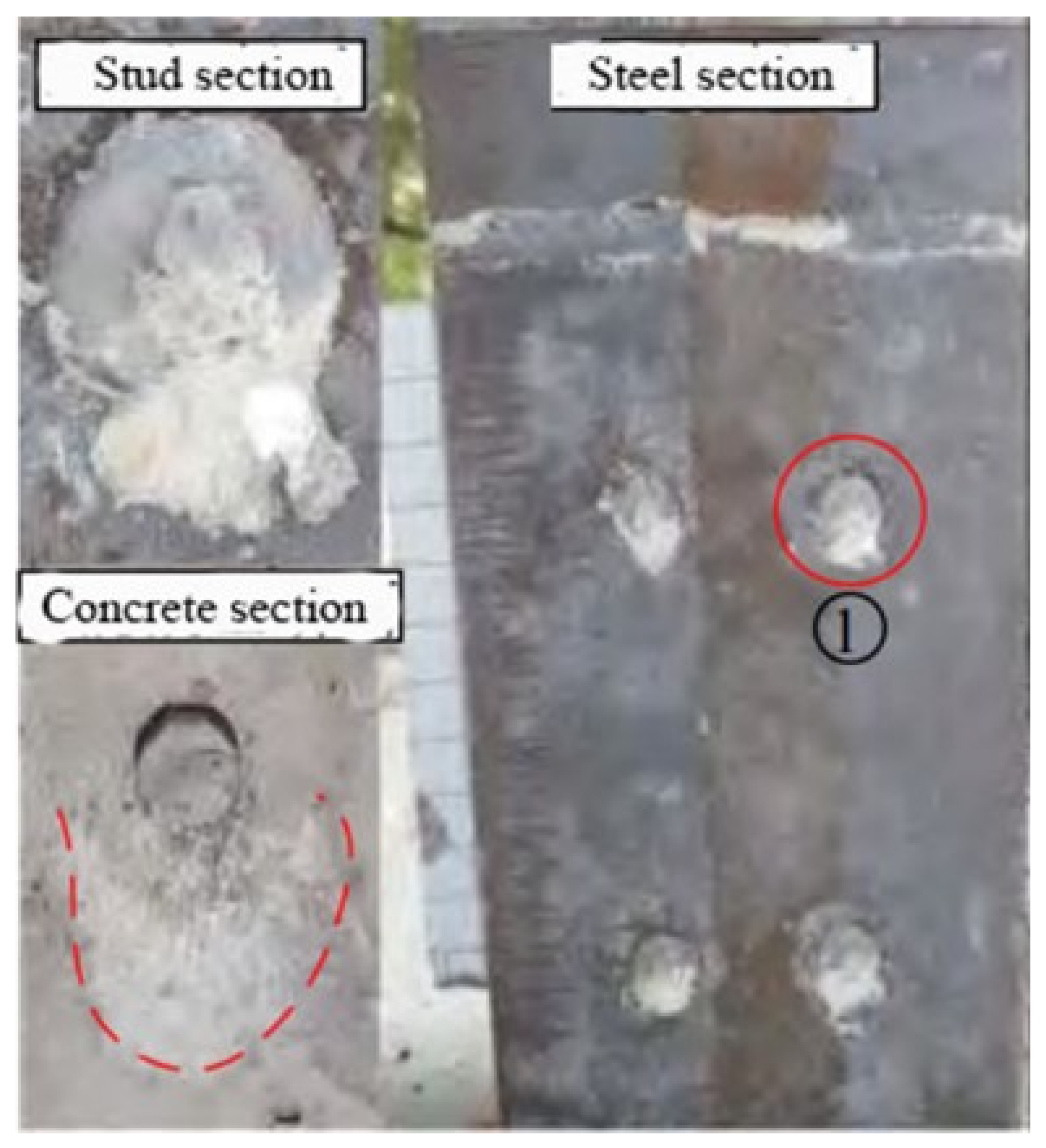
  • Reported studies show that the failure mode of shear studs in the UHPC layer under the ultimate bearing capacity state is dominated by shear fractures. However, as the slenderness of headed shear studs changes, the failure pattern of shear studs in composite decks needs to be further studied.
  • In the existing studies, no cracking occurred in the UHPC layer of the composite deck under the in-service loads. However, the relevant tests can only reflect the tensile stress in the local structure. The stress inside the UHPC layer shall consider the stress superposition effect in both the whole bridge and local structure.
  • The steel–UHPC composite deck shows good fatigue performance since the stress range of all fatigue-prone details shows different degrees of reduction. It is more reasonable to evaluate the fatigue performance of the composite deck through the field test under in-service traffic flows. This approach can provide a more real structural system, fabrication process, boundary conditions, and traffic loading conditions, which will facilitate a more reasonable estimation of fatigue.
  • According to the current study, some reasonable parameters or structural layouts in the traditional OSDs may not be the optimal solution for the fatigue design of the steel–UHPC composite deck. However, new fatigue details applied to the composite deck need to be checked by bridge engineering practices.

5.2. Propects

  • In steel–UHPC composite decks, shear connectors are key components for joint action between the OSD and UHPC layer. The main function of the shear connection is to transfer the shear force between the two parts and ensure their performance as composite structures under in-service loads. In bridge service conditions, the individual or jointed action of temperature, traffic flow, structural layer thickness, and other factors on bridge operation are considered to determine the specific failure mode of shear studs in composite structures.
  • Due to the complicated stress mechanism of the steel–UHPC composite deck under concentrated wheel loads, the stress in the UHPC layer is highly dependent on its location and wheel location. Most experiments and FEM analyses only focus on the stress characteristics of the OSD, with few considerations on the UHPC layer. It is necessary to investigate the stress behavior of UHPC layers in different scenarios in future research.
  • As a newly developed deck system, the removal or replacement of the UHPC layer in case of damage should be considered. However, due to the high strength of the UHPC and its strong connection with the OSD, the method of construction and the stress in the process of construction will be a concern, and hence, it should be investigated in the future.

Funding

This research was funded by the National Natural Science Foundation of China (51878269, 52278509).

Data Availability Statement

Not applicable.

Conflicts of Interest

The authors declare no conflict of interest.

References

  1. Zhao, Q. Steel Bridge-Steel Structure and Composite Structure Bridge; China Communications Press: Beijing, China, 2017; pp. 39–45. [Google Scholar]
  2. Wang, T.; Zhu, Z.W.; Xiang, J.J. Stress response characteristics of arcuate notch of orthotropic steel bridge panel under random traffic flow. Highw. Eng. 2016, 41, 66–71. [Google Scholar]
  3. Yang, S.L.; Shi, Z. Current Research of Fatigue Damage in Orthotropic Deck Plates of Long Span Steel Box Girder Bridges in China. Bridge Constr. 2017, 47, 60–65. [Google Scholar]
  4. Kim, T.W.; Baek, J.; Lee, H.J.; Lee, S.Y. Effect of pavement design parameters on the behaviour of orthotropic steel bridge deck pavements under traffic loading. Int. J. Pavement Eng. 2014, 15, 471–482. [Google Scholar] [CrossRef]
  5. Zhang, Q.H.; Bu, Y.Z.; Li, Q. Review on Fatigue Problems of Orthotropic Steel Bridge Deck. China J. Highw. Transp. 2017, 3, 15–28. [Google Scholar]
  6. Zhu, Z.W.; Huang, Y.; Wang, T.; Wen, P.X.; Xiang, J.J. Fatigue performance evaluation of composite bridge panels of Fochen Extension Bridge under random traffic flow. Highw. Eng. 2016, 31, 3267–3277. [Google Scholar]
  7. Wang, C.S.; Fu, B.N.; Zhang, Q.; Feng, Y.C. Fatigue Test on Full-scale Orthotropic Steel Bridge Deck. China J. Highw. Transp. 2013, 3, 69–76. [Google Scholar]
  8. Zhang, Q.H.; Cui, C.; Bu, Y.Z.; Li, Q. Study on fatigue features of orthotropic decks in steel box girder ofHong Kong-Zhuhai-Macao Bridge. China Civ. Eng. J. 2014, 9, 110–119. [Google Scholar]
  9. Zweraeman, F.J.; Frank, K.H. Fatigue Damage under Variable Amplitude Loads. J. Struct. Eng. 1988, 114, 67–83. [Google Scholar] [CrossRef]
  10. Connor, R.J.; Fisher, J.W. Consistent Approach to Calculating Stresses for Fatigue Design of Welded Rib-to-Web Connections in Steel. J. Bridge Eng. 2006, 11, 517–525. [Google Scholar] [CrossRef]
  11. Connor, R.J.; Fisher, J.W. Identifying Effective and Ineffective Retrofits for Distortion Fatigue Cracking in Steel Bridges Using Field Instrumentation. J. Bridge Eng. 2006, 11, 745–752. [Google Scholar] [CrossRef]
  12. Shao, X.D.; Hu, J.H. The Steel-UHPC Lightweight Composite Bridge Structures; China Communications Press: Beijing, China, 2015; pp. 30–31. [Google Scholar]
  13. Bache, H.H. Model for strength of brittle materials built up of particles joined at points of contact. J. Am. Ceram. Soc. 1970, 53, 654–658. [Google Scholar] [CrossRef]
  14. Bache, H.H. Densified cement ultra fine particle based materials. In Proceedings of the the Second International Conference on Superplasticizers in Concrete, Ottawa, ON, Canada, 10–12 June 1981. [Google Scholar]
  15. Zhao, M.; He, X.F.; Qiu, M.H.; Yan, B.F.; Shao, X.D. Research on Design and Application of Fully Prefabricated Steel-UHPC Lightweight Composite Girder in Medium and Small Span Girder Bridge. Highw. Eng. 2019, 44, 63–66. [Google Scholar]
  16. Wan, J.J.; Du, R.Y.; Jie, X.D.; Dai, L.; Zhou, X.P.; Lu, Y. Study on Preparation of Ultra High Performance Concrete (UHPC). Jiangxi Build. Mater. 2022, 12, 7–9. [Google Scholar]
  17. Yao, S.; Yang, Z.P.; Ge, W.J.; Hu, Y.X.; Li, W.; Sun, C.Z.; Yan, W.H.; Cao, D.F. Analysis on working and mechanical properties of ultra-high performance concrete. Build. Struct. 2023, 53, 142–147. [Google Scholar]
  18. Shao, X.D.; Qiu, M.H.; Yan, B.F.; Luo, J. A Review on the Research and Application of Ultra-high Performance Concrete in Bridge Engineering Around the World. Mater. Rep. 2017, 31, 33–42. [Google Scholar]
  19. Jiang, X.; Tang, D.Y.; Hu, S.T.; Zhang, Z.Y.; Shi, L. Application of Ultra-High Performance Concrete in Bridge Engineering all over the World. Railw. Eng. 2021, 61, 1–7. [Google Scholar]
  20. Shao, X.D.; Fan, W.; Huang, Z.Y. Application of Ultra-High-Performance Concrete in engineering structures. China Civ. Eng. J. 2021, 54, 1–13. [Google Scholar]
  21. Teng, H.J.; Zhu, Z.W.; Li, J.P. Research on Vertical Temperature Gradient of Steel Box Girders on Steel Bridge Deck Based on Field Measurements. J. Railw. Sci. Eng. 2021, 18, 30–37. [Google Scholar]
  22. Wang, Q.H.; Qiao, H.S.; Dario, D.D.; Zhu, Z.W.; Tang, Y. Seismic performance of optimal Multi-Tuned Liquid Column Damper-Inerter (MTLCDI) applied to adjacent high-rise buildings. Soil Dyn. Earthq. Eng. 2021, 143, 106653. [Google Scholar] [CrossRef]
  23. De Jong, F.B.P.; Kolstein, M.H. Strengthening a bridge deck with high performance concrete. In Proceedings of the 2004 Orthotropic Bridge Conference, Sacramento, CA, USA, 25–27 August 2004. [Google Scholar]
  24. Ekkehard, F.; Kai, B.; Michael, S. Gärtnerplatz-Bridge over River Fulda in Kassel: Multispan Hybrid UHPC-Steel Bridge. In Proceedings of the UHPFRC 2009, Marseille, France, 17–18 November 2009. [Google Scholar]
  25. Ziad, H.; Marco, N.; Claude, S.; Grégory, G.; Davy, P.; Daniel, B. Innovative solution for strengthening orthotropic decks using uhpfrc: The Illzach Bridge. In Proceedings of the Symposium on Ultra-High Performance Fibre-Reinforced Concrete, UHPFRC 2013, Marseille, France, 1–3 October 2013. [Google Scholar]
  26. Li, J.; Feng, X.T.; Shao, X.D.; Gu, J.K. Research on Composite Paving System with Orthotropic Steel Bridge Deck and Thin RPC Layer. J. Hunan Univ. Nat. Sci. 2012, 39, 1–12. [Google Scholar]
  27. Shao, X.D.; Cao, J.H.; Yi, D.T.; Chen, B.; Huang, Z.Y. Research on Basic Performance of Composite Bridge Deck System with Orthotropic Steel Deck and Thin RPC Layer. China J. Highw. Transp. 2012, 2, 44–49. [Google Scholar]
  28. Shao, X.D.; Wu, J.J.; Liu, R.; Li, Z.H. Basic performance of Waffle deck of lightweight steel-UHPC composite bridge. China J. Highw. Transp. 2017, 30, 219–225. [Google Scholar]
  29. Shao, X.D.; Zheng, H.; Huang, X.J.; Peng, B. Transversal Mechanical Behavior of Steel-UHPC Light-weighted Composite Bridge Deck System. China J. Highw. Transp. 2017, 30, 70–77+85. [Google Scholar]
  30. Shao, X.D.; Chen, B.; Zhou, X.H. Experiment on Bending Behavior of Wet Joints in Light-weighted Composite Deck System Composed of Steel and RPC Layer. China J. Highw. Transp. 2017, 30, 210–217. [Google Scholar]
  31. Shao, X.D.; Luo, J.; Cao, J.H.; Fan, W.; Wang, Y. Experimental study and crack width calculation of steel-UHPC lightweight composite deck structure. J. Civ. Eng. 2019, 52, 61–75. [Google Scholar]
  32. Shao, X.D.; Gan, Y.D.; Li, J.; Cao, J.H.; Qiu, M.H. Interfacial Shear Resistance of Welded Structure of Composite Deck System Composed of Orthotropic Deck and Ultrathin UHPC Layer. China J. Highw. Transp. 2018, 31, 91–101. [Google Scholar]
  33. Shao, X.D.; Qv, W.T.; Cao, J.H.; Yao, Y.L. Fundamental mechanical performance of lightweight composite bridge deck with large U-ribs. China J. Highw. Transp. 2018, 31, 94–103. [Google Scholar]
  34. Shao, X.D.; Zhou, Y.D.; Cao, J.H.; Sun, P.K.; Zhu, F.X. Experimental study on flexural behavior of novel continuous deck structure in steel simply-supported beams. J. Civ. Eng. 2019, 52, 80–92. [Google Scholar]
  35. Shao, X.D.; Zhang, H.W.; Li, J.; Cao, J.H.; Gan, Y.D. Research on shear performance of short rebar connectors in steel-ultra thin lightweight composite deck. J. Civ. Eng. 2020, 53, 39–51. [Google Scholar]
  36. Li, W.G.; Shao, X.D.; Fang, H.; Zhang, Z. Experimental study on flexural behavior of Steel-UHPC composite slabs. J. Civ. Eng. 2015, 48, 93–102. [Google Scholar]
  37. Kong, L.F.; Shao, X.D.; Liu, R. Finite element analysis of flexural behavior of steel-UHPC lightweight composite grider deck. J. Highw. Commun. Technol. 2016, 33, 88–95. [Google Scholar]
  38. Li, J.; Yang, B.; Shao, X.D.; Li, J. Research on shear fatigue of studs for composite deck system ofsteel slab and thin CRRPC layer. J. Civ. Eng. 2016, 6, 67–75. [Google Scholar]
  39. Peng, B.; Shao, X.D. Study on fatigue performance of closed ribbed lightweight composite bridge panel. J. Civ. Eng. 2016, 50, 89–96. [Google Scholar]
  40. Liao, Z.N.; Shao, X.D.; Qiao, Q.H.; Cao, J.H.; Liu, X.N. Static test and finite element simulation analysis of transverse bending of steel-ultra-high performance concrete composite slabs. J. Zhejiang Univ. Eng. Sci. 2018, 52, 1954–1963. [Google Scholar]
  41. Luo, J. Theoretical Study on Structural Mechanical Properties and Crack Width Calculation of Steel-UHPC Lightweight Composite Deck. Ph.D. Thesis, Hunan University, Changsha, China, 2013. [Google Scholar]
  42. Dieng, L.; Marchand, P.; Gomes, F.; Tessier, C.; Toutlemonde, F. Use of UHPFRC overlay to reduce stresses in orthotropic steel decks. J. Constr. Steel Res. 2013, 89, 30–41. [Google Scholar] [CrossRef]
  43. Li, J.; Li, J.; Shao, X.D.; Chen, W.; Zeng, Y. Static and fatigue tests on composite deck with steel and ultra-thin UHPC-TPO. J. Civ. Eng. 2017, 11, 98. [Google Scholar]
  44. Shao, X.D.; Zhang, Z.; Liu, M.L.; Cao, J.H. Research on Bending Tensile Strength for Composite Bridge Deck System Composed of Orthotropic Steel Deck and Thin RPC Topping. J. Hunan Univ. Nat. Sci. 2012, 39, 7–13. [Google Scholar]
  45. Shao, X.D.; Li, Z.H.; Wu, J.J.; Huang, X.J. Experimental on Partial Repair Technology of Light-weight Composite Bridge Deck Composed of Steel and UHPC Layer. China J. Highw. Transp. 2017, 30, 58–64. [Google Scholar]
  46. Wu, J.J.; Shao, X.D.; Liu, R. Structural feature research on UHPC deck of Steel-UHPC lightweight composite beam. Highw. Eng. 2017, 42, 76–81. [Google Scholar]
  47. Bu, Y.Z.; Liu, X.Y.; Zhang, Q.H. Cracking load calculation for Steel-UHPC composite slabs based on the section-stress method. Eng. Mech. 2020, 10, 209–217. [Google Scholar]
  48. Fang, Z.; Wu, X.N.; Tan, X.Y.; Liao, Y.; Yang, Y.; Tang, S.F. Transverse flexural behavior of Steel-UHPC composite deck under hogging moment. Eng. Mech. 2022, 39, 1–13. [Google Scholar]
  49. Zhou, M.; Xiao, J.L.; Yang, T.Y.; Nie, J.G.; Fan, J.S. Experimental and numerical investigation on the flexural behavior of Steel-UHPC composite slabs with perforated rib shear connectors. China J. Highw. Transp. 2022, 39, 19–28. [Google Scholar]
  50. Rafiee, A. Computer Modeling and Investigation on the Steel Corrosion in Cracked Ultra High Performance Concrete; University of Kassel: Kassel, Germany, 2012. [Google Scholar]
  51. Luo, J.; Shao, X.D.; Cao, J.H.; Xiong, M.H.; Fan, W. Transverse bending behavior of the steel-UHPC lightweight composite deck: Orthogonal test and analysis. J. Constr. Steel Res. 2019, 162, 105708. [Google Scholar] [CrossRef]
  52. Shao, X.D.; Guo, C.; Cao, J.H. Design of Bolted Joint Region for Steel-STC Lightweight Composite Bridge Deck. China J. Highw. Transp. 2019, 32, 57–65. [Google Scholar]
  53. Wang, Z.W.; Chen, J.; Wei, C.; Li, M.Z.; Zhang, Q.H. Experimental Study on Flexural Behavior of Steel-UHPC Composite Deck Slab with FRP Bars. Bridge Constr. 2023, 53, 44–51. [Google Scholar]
  54. Han, F.Y.; Liu, J.Z.; Liu, J.P.; Wan, H.Y.; Lin, W.; Wan, Y.; Zheng, X.B. Shrinkage Restraint Stress in Ultra-high Performance Concrete Surface of Steel Bridge Deck. J. Chin. Ceram. Soc. 2020, 48, 1701–1705. [Google Scholar]
  55. Liu, Y.M.; Zhang, Q.H.; Bu, Y.Z.; Tian, Q.X. Study on Mechanical Performance of Composite Deck System Consisting Of Large Longitudinal-Rib Orthotropic Steel Plates and Steam-Curing-Free UHPC Overlay. Bridge Constr. 2023, 53, 36–43. [Google Scholar]
  56. Shao, X.D.; Mo, R.; Cao, J.H.; Chen, Y.B. Study on Crack-resisting Performance of Steel-UHPC Lightweight Composite Deck Structure Subjected to Simulated Traffic Disturbance. J. Hunan Univ. 2022, 49, 1–13. [Google Scholar]
  57. Shao, X.D.; Zhou, H.Y.; Cao, J.H. Shear Behavior of Studs of Composite Deck System Composed of Steel and Ultrathin RPC Layer. J. Highw. Commun. Technol. 2013, 30, 34. [Google Scholar]
  58. Wang, J.Q.; Qi, J.N.; Tong, T.; Xu, Q.Z.; Xiu, H.L. Static behavior of large stud shear connectors in steel-UHPC composite structures. Eng. Struct. 2019, 178, 543. [Google Scholar] [CrossRef]
  59. Shao, X.D.; Li, M.; Cao, J.H.; He, G.; Chen, Y.B.; Zhao, X.D. Experimental Research and Theoretical Analysis on Shear Performance of Short Headed Studs Embedded in UHPC. China J. Highw. Transport. 2021, 1, 1–19. [Google Scholar]
  60. Wu, F.W.; Feng, Y.P.; Dai, J.; Wang, G.Q.; Zhang, J.F. Study on mechanical properties of stud shear connectors in Steel-UHPC composite structures. Eng. Mech. 2022, 39, 222–234+243. [Google Scholar]
  61. Huang, X.H.; Zhuang, D.K.; Cheng, S.S. Experimental Study on Shear Resistance of High Strength Bolt Shear Key of Steel-UHPC Composit eBeam. J. Chongqing Jiaotong Univ. Sci. 2022, 8, 73–78. [Google Scholar]
  62. Deng, M.; Huo, N.; Shi, G.; Zhang, J. Shear strength analysis of the stud in steel-UHPC composite bridge deck. In IOP Conference Series: Earth and Environmental Science; IOP Publishing: Bristol, UK, 2017; Volume 100. [Google Scholar]
  63. Guo, Y.W.; Ling, L.P. Experimental Research on Large Full-scale Steel-UHPC Composite Bridge Deck Model. Constr. Technol. 2023, 52, 76–80. [Google Scholar]
  64. Sun, Q.L.; Lu, X.Y.; Nie, X.; Han, Z.J.; Fan, J.S. Experimental research on tensile and shear behaviour of the interface between non-steam-cured UHPC and steel plate structure. Eng. Mech. 2017, 34, 167–174+192. [Google Scholar]
  65. He, Q.S.; Zhang, H.L.; Li, J.; Duan, H.H. Performance evaluation of polyurethane/epoxy resin modified asphalt as adhesive layer material for steel-UHPC composite bridge deck pavements. Constr. Build. Mater. 2021, 291, 123364. [Google Scholar] [CrossRef]
  66. Johnson, R.; May, I. Partial-interaction design of composite beams. Struct. Eng. 2021, 8, 305–311. [Google Scholar]
  67. ISSC. Guidelines for Performance-Based Design of Steel-Concrete Hybrid Structures; Japan Society of Civil Engineers: Tokyo, Japan, 2002; pp. 1–201. [Google Scholar]
  68. Cao, J.H. Study on the Basic Performance of Steel-Thin Layer Ultra-High Performance Concrete Lightweight Composite Deck Structure. Ph.D. Thesis, Hunan University, Changsha, China, 2016. [Google Scholar]
  69. Li, C.; Chen, B.C.; Hu, W.X.; Su, J.Z. Calculation of shear bearing capacity, slip and stiffness of headed studs in Steel-UHPC composite slab. Eng. Mech. 2022, 10, 1–14. [Google Scholar]
  70. Liu, P. Orthogonal Anisotropic Plate—Reactive Powder Concrete (RPC) Composite Beam Interface Shear Analysis. Master’s Thesis, Hunan University, Changsha, China, 2012. [Google Scholar]
  71. Shao, X.D.; Tang, Y.; Wang, Z.J.; Qiu, M.H. Experimental Research on Hybrid of Stud and PBL Shear Connector of Steel-UHPC Interface. J. Hunan Univ. Nat. Sci. 2022, 8, 1–14. [Google Scholar]
  72. Li, J.; Feng, X.T.; Shao, X.D.; Wang, Y.; Cao, J.H. Comparison of Mechanical Calculation and Actual Test forNew STC Steel Bridge Paving System. China J. Highw. Transp. 2014, 27, 39–50. [Google Scholar]
  73. Zhang, L.W.; Zhao, H.; Tan, C.J.; Shao, X.D.; Cao, J.H. Stress Analysis on Cutout at Welded Rid-to-diaphragm Connections in aLight-weight Steel-UHPC Composite Deck. China J. Highw. Transp. 2016, 29, 75–81. [Google Scholar]
  74. Li, J.P.; Zhu, Z.W. Stress Behaviors at Rib-to-Floorbeam Weld and Cutout Details under Controlled Truck Loading. Appl. Sci. 2022, 12, 3012. [Google Scholar] [CrossRef]
  75. Yuan, Y.; Wu, C.; Jiang, X. Experimental study on the fatigue behavior of the orthotropic steel deck rehabilitated by UHPC overlay. J. Constr. Steel Res. 2019, 157, 1–19. [Google Scholar] [CrossRef]
  76. Wang, Y.; Shao, X.D.; Chen, J.; Cao, J.H.; Wang, L.G. UHPC-based strengthening technique for significant fatigue cracking steel bridge decks. J. Civ. Eng. 2020, 53, 92–101. [Google Scholar]
  77. Liu, M.L.; Shao, X.D.; Zhang, Z.; Hu, J. Experiment on Flexural Fatigue Performance of Composite Deck System Composed of Orthotropic Steel Deck and Ultra-thin RPC Layer. J. Highw. Transp. Res. Dev. 2012, 29, 46–52. [Google Scholar]
  78. Ding, N.; Shao, X.D. Study on fatigue performance of lightweight composite bridge panels. J. Civ. Eng. 2015, 48, 74–81. [Google Scholar]
  79. Zhu, Z.W.; Huang, Y.; Wen, P.X.; Chen, W.; Yu, P.; Shi, Y.G.; Shao, X.D. Investigation on fatigue performance of orthotropic bridge deck with steel-UHPC composite system under random traffic Flows. China J. Highw. Transp. 2017, 30, 200–209. [Google Scholar]
  80. Zhu, Z.W.; Yuan, T.; Xiang, Z.; Huang, Y.; Zhou, Y.E.; Shao, X.D. Behavior and Fatigue Performance of Details in an Orthotropic Steel Bridge with UHPC-Deck Plate Composite System under In-Service Traffic Flows. J. Bridge Eng. 2017, 23, 04017142. [Google Scholar] [CrossRef]
  81. Li, J.P.; Zhu, Z.W. Effects of full internal bulkheads on fatigue behaviors of orthotropic steel decks. J. Constr. Steel Res. 2022, 196, 107400. [Google Scholar] [CrossRef]
  82. Zhu, Z.W.; Li, J.P.; Chen, X.W.; Carpinteri, A. Stress behaviors of rib-to-deck double-sided weld detail on orthotropic steel deck. J. Constr. Steel Res. 2021, 187, 106947. [Google Scholar] [CrossRef]
  83. Tian, Q.X.; Gao, L.Q.; Zhou, S.M. Study on mechanical behavior of super high performance concrete-teel orthotropic composite deck. Bridge Constr. 2017, 47, 13–18. [Google Scholar]
  84. Deng, L.; Xian, Y.L.; Shao, X.D. Fatigue reliability assessment of light-weighted steel-UHPC composite bridge deck. J. Cent. South Univ. Sci. Technol. 2018, 49, 711–717. [Google Scholar]
  85. Zhu, Z.W.; Li, J.P.; Huang, Y.; Carpinteri, A. Hot-spot stress models of cutout detail on orthotropic steel bridge decks. J. Constr. Steel Res. 2021, 183, 106762. [Google Scholar] [CrossRef]
  86. Zhu, Z.W.; Xiang, Z.; Zhou, Y.E. Fatigue behavior of orthotropic steel bridge stiffened with ultra-high performance concrete layer. J. Constr. Steel Res. 2019, 157, 132–142. [Google Scholar] [CrossRef]
  87. Xiong, C.Q.; Zhu, Z.W.; Li, J.P. Response Surface-Based Finite Element Model Updating of Steel Box-Girder Bridges with Concrete Composite Decks. Adv. Civ. Eng. 2022, 2022, 4298933. [Google Scholar] [CrossRef]
  88. Chen, S.M.; Huang, Y.; Gu, P.; Wang, J.Y. Experimental study on fatigue performance of UHPC-orthotropic steel composite deck. Thin-Walled Struct. 2019, 142, 1–18. [Google Scholar] [CrossRef]
  89. Zhan, J.; Shao, X.D.; Qv, W.T.; Cao, J.H. Multi-parameter analysis of steel-STC lightweight composite bridge deck. J. Highw. Commun. Technol. 2018, 35, 73–81. [Google Scholar]
  90. Xiang, Z.; Zhu, Z.W. Simulation study on fatigue behavior of wrap-around weld at rib-to-floorbeam joint in a steel-UHPC composite orthotropic bridge deck. Constr. Build. Mater. 2021, 289, 123161. [Google Scholar] [CrossRef]
  91. Xiang, Z.; Zhu, Z.W. Fatigue behavior of orthotropic composite bridge decks without cutout at rib-to-floorbeam intersection. J. Constr. Steel Res. 2023, 201, 107596. [Google Scholar] [CrossRef]
  92. Zhu, Z.W.; Xiang, Z.; Li, J.P. Fatigue damage investigation on diaphragm cutout detail on orthotropic bridge deck based on field measurement and FEM. Thin-Walled Struct. 2020, 157, 107106. [Google Scholar] [CrossRef]
  93. Zhu, Z.W.; Xiang, Z. Fatigue cracking investigation on diaphragm cutout in a self-anchored suspension bridge with orthotropic steel deck. Struct. Infrastruct. Eng. 2019, 15, 1279–1291. [Google Scholar] [CrossRef]
  94. Cao, J.H.; Shao, X.D.; Deng, L.; Gan, Y.D. Static and Fatigue Behavior of Short-Headed Studs Embedded in a Thin Ultrahigh-Performance Concrete Layer. J. Bridge Eng. 2017, 22, 04017005. [Google Scholar] [CrossRef]
  95. Liu, C.; Fan, J.S.; Nie, J.G.; Hu, J.H.; Cui, J.F.; Tang, L. Fatigue Performance Research of Headed Studs in Steel andUltra-high Performance Concrete Composite Deck. China J. Highw. Transp. 2017, 30, 139–145. [Google Scholar]
  96. Shi, Z.C.; Su, Q.T.; Chen, L. Fatigue behavior and design and arrangement of welded studs in Steel-UHPC composite bridge panel. China J. Highw. Transp. 2022, 9, 1–19. [Google Scholar]
  97. Shi, Z.C.; Su, Q.T.; Florentia, K.; Veljkovic, M. Behavior of short-headed stud connectors in orthotropic steel-UHPC composite bridge deck under fatigue loading. Int. J. Fatigue 2022, 160, 106845. [Google Scholar] [CrossRef]
  98. Xiang, Z. Study on Rational Structure of Steel-UHPC Composite Orthotropic Bridge Panel. Ph.D. Thesis, Hunan University, Changsha, China, 2016. [Google Scholar]
  99. Zhang, S.H.; Shao, X.D.; Cao, J.H.; Hu, J.H.; Deng, L. Fatigue Performance of a Lightweight Composite Bridge Deck with Open Ribs. J. Bridge Eng. 2016, 21, 04016039. [Google Scholar] [CrossRef]
  100. Xiang, Z.; Zhu, Z.W. Multi-objective optimization of a composite orthotropic bridge with RSM and NSGA-II algorithm. J. Constr. Steel Res. 2022, 188, 106938. [Google Scholar] [CrossRef]
  101. Liu, Y.M.; Zhang, Q.H.; Meng, W.N.; Bao, Y.; Bu, Y.Z. Transverse fatigue behaviour of steel-UHPC composite deck with large-size U-ribs. Eng. Struct. 2019, 180, 388–399. [Google Scholar] [CrossRef]
Figure 1. Typical structural layout of OSD.
Buildings 13 01906 g001
Figure 2. The typical locations of fatigue cracking: (a) Rib-to-deck crack; (b) Rib-to-floorbeam crack; (c) Cutout crack; (d) Rib splice crack.
Buildings 13 01906 g002
Figure 3. Material used to form UHPC: (a) Cement; (b) Silica fume; (c) Quartz sand; (d) Fly ash; (e) Water reducer; (f) Fiber.
Buildings 13 01906 g003
Figure 4. Measured temperature of deck overlay and its elastic modulus of EAC against temperature: (a) Measured temperature of steel girder and its overlay; (b) Elastic modulus of EAC against temperature.
Buildings 13 01906 g004
Figure 5. UHPC construction process.
Buildings 13 01906 g005
Figure 6. UHPC construction process: (a) Welded shear stud; (b) Steel mesh; (c) Pouring UHPC; (d) Steam curing.
Buildings 13 01906 g006
Figure 7. Deck replacement of Galand Bridge using glued UHPC layer.
Buildings 13 01906 g007
Figure 8. Mafang Bridge using steel–UHPC composite deck: (a) Under construction; (b) After 12 years in service.
Buildings 13 01906 g008
Figure 9. Bridge deck under construction: (a) Fochen New Bridge; (b) Hangrui Dongting Lake Bridge; (c) Queshi Bridge; (d) Fengxi Bridge.
Buildings 13 01906 g009
Figure 10. Wheel load on orthotropic steel–UHPC composite deck in bridge transverse direction: (a) Negative moment zone at top of longitudinal rib; (b) Positive moment zone between longitudinal ribs.
Buildings 13 01906 g010
Figure 11. Photo of stud shear failure.
Buildings 13 01906 g011
Figure 12. Measured stress time histories and stress spectrum [79]: (a) 24 h stress time records at RD-D; (b) 24 h stress time records at RD-R; (c) One-week stress spectrum at RD-D; (d) One-week stress spectrum at RD-R.
Buildings 13 01906 g012
Figure 13. Stress contour plots for four different cutout clearances. (a) 20 mm. (b) 30 mm. (c) 40 mm. (d) 50 mm.
Buildings 13 01906 g013
Figure 14. Distortion of rib wall under wheel loads.
Buildings 13 01906 g014
Figure 15. The stress contour of RF joint using various thicknesses at rib belly: (a) 10 mm; (b) 12 mm; (c) 14 mm; (d) 16 mm.
Buildings 13 01906 g015
Figure 16. Static (a) and fatigue (b) failure mode of shear stud of steel–UHPC composite models.
Buildings 13 01906 g016
Figure 17. S–N curves for shear stud in UHPC composite deck. (a) S-N curves for headed studs against shear stress. (b) Comparison of S-N curves between this experiment and literature.
Buildings 13 01906 g017
Figure 18. Variation of stress ranges of RF detail against floorbeam thicknesses.
Buildings 13 01906 g018
Table 2. Newly built bridge using orthotropic steel–UHPC composite deck in China.
Bridge NameLocationSpan Arrangement/mTypeYear
FochenFoshan, Guangdong58.51 + 112.8 + 58.512014
Hexi Trans. HubChangsha, Hunan542015
Beiguan TonghuiheTongzhou, Beijing11.5 + 60 + 18.5
HaiheTianjin310 + 4 × 48
Longxi Interchange RampJiangmen, Guangdong28 + 50 + 282016
ShendangJiaxing, Zhejiang72
JiaoshanmenJiaxing, Zhejiang36.5
Beiguan StreetTongzhou, Beijing30 + 40 + 70 + 40 + 30
LichuanDongguan, Guangdong138
FengxiZhuzhou, Hunan300
Chetian RiverGuiyang, Guizhou32 + 56 + 322017
TongguanChangsha, Hunan50 + 50
WuyiHuzhou, Zhejiang60 + 128 + 60
Gangxia North Trans. HubShenzhen, Guangdong30 + 2 × 46 + 34 + 32
SheleTaiyuan, Shanxi30 + 150 + 150 + 30
Hangrui Dongting LakeYueyang, Hunan1480
ZhaohuaXiangtan, Hunan168 + 228
Fute BayFoshan, Guangdong112 + 2 × 200 + 1122018
Jinan Guodian InterchangJinan, Shandong21.5 + 22 + 26 + 22 + 20
Beiyuan Expressway WestJinan, Shandong30 + 47 + 30
Da’an North InterchangeBaicheng, Jilin31.2
Tiansheng Harbour and FerryNantong, Jiangsu141.5 + 336 + 141.8
Beijiang River FourthQingyuan, Guangdong100 + 218 + 100
Maogang RiverShanghai110 + 225 + 110
TianbaowanChengdu, Sichuan2302019
HongfengluChangsha, Hunan30 + 70 + 30
LongshengHuizhou, Guangdong40 + 185 + 40
HaiwenHaikou, Hainan230 + 230
ZhongxingNingbo, Zhejiang64 + 86 + 400 + 86 + 64
Jingzhou Yangtze RiverJingzhou, Hubei98 + 182 + 518 + 182 + 98
YunlongwanChengdu, Sichuan30 + 80 + 205 + 80 + 30
QinglongzhouYiyang, Hunan60 + 110 + 260 + 110 + 60
Dashahe 1st Road CrossingShenzhen, Guangdong752020
Hutong Yangtze RiverSuzhou, Jiangsu140 + 462 + 1092 + 462 + 140
Jiangxinzhou Yangtze RiverNanjing, Jiangsu80 + 218 + 2 × 600 + 218 + 80
RongjiangJieyang, Guangdong400
XinglinbaoZhangjiakou, Hebei217
Taizicheng No.1Zhangjiakou, Hebei50 + 100 + 100 + 50
HongheYuanyang, Yunnan700
Qiushi Road SteelUrumqi, Xinjiang42 + 68 + 68 + 422021
Shennong LakeChangzhi, Shanxi130 + 130
QipanzhouHuangshi, Hubei340 + 1038 + 340
ShachongDongguan, Guangdong9 + 88 + 92022
Binhai BayDongguan, Guangdong60 + 200 + 200 + 60
Sangyuanzi Yellow RiverLanzhou, Gansu949 + 328 + 959
Fulong Xijiang GrandFoshan, Guangdong500
Danjiangkou ShuikuteDanjiangkou, Hubei106.2 + 760 + 106.2
Yellow River FenghuangJinan, Shandong70 + 168 + 428 + 428 + 168 + 70
① girder bridge; ② arch bridge; ③ cable-stayed bridge; ④ suspension bridge.
Table 3. Deck replacement using steel–UHPC composite structure.
Bridge NameLocationSpan Arrangement/mTypeYear
MafangZhaoqing, Guangdong14 × 642011
QueshiShantou, Guangdong5182016
Riyue-Chengwen Road ExpresswayChengdu, Sichuan37 + 46 + 46 (Left) 46 + 46 + 42 (Right)2018
JunshanWuhan, Hubei48 + 204 + 460 + 204 + 48
Lanzhou Donggang InterchangeLanzhou, Gansu5952019
SongpuJShanghai419.62020
Shengli Yellow RiverDongying, Shandong682
HongtangFuzhou, Fujian50 + 150 + 150 + 502021
Yichang Yangtze RiverYichang, Hubei960
① girder bridge; ② arch bridge; ③ cable-stayed bridge; ④ suspension bridge.
Disclaimer/Publisher’s Note: The statements, opinions and data contained in all publications are solely those of the individual author(s) and contributor(s) and not of MDPI and/or the editor(s). MDPI and/or the editor(s) disclaim responsibility for any injury to people or property resulting from any ideas, methods, instructions or products referred to in the content.

