Abstract
Concrete structures in marine environments are prone to deterioration and damage due to chloride ion penetration, freezing and thawing, and chemical erosion. Ultra-high-performance concrete (UHPC) mixed with steel fibers has been proposed as a solution to enhance the durability and mechanical properties of concrete in marine environments. Although several studies have been conducted in this regard, they have yet to focus on addressing errors that may be caused during the construction of offshore piers. Therefore, this study proposes a modular system to control horizontal and vertical errors during construction using a new connecting core type. UHPC with a fiber content of 0.75% was considered the optimum mix proportion because this met the tensile and compressive strength requirements and the chloride attack resistibility requirements of marine structures. The structural performance of a specimen constructed using modular technology was evaluated. The results of the lateral load resistance experiments showed minimal deformation in the girder and pier. Additionally, both the precast and cast-in-place types met the criterion of load resistance. This study contributes to the advancement of construction technology in marine environments by considering both material performance and construction conditions.
1. Introduction
Concrete has been considered a construction material suitable for various construction fields because it is more resistant to external environmental exposure than steel structures and has economic advantages during construction. Marine concrete structures, however, suffer from cracking, peeling, failure, and rebar corrosion caused by chloride ion penetration, freezing and thawing, and chemical erosion over time, which may shorten their service life or make maintenance difficult [1,2,3,4]. Concrete in the marine environment is exposed to composite degradation factors due to the environmental impact of the sea and high solar irradiation [5]. In the marine environment, the influence of saltwater can be considered the most representative factor [6,7]. Concrete absorbs water, and structures adjacent to the sea are exposed to large amounts of saltwater. Such chlorides adversely affect the durability of concrete and significantly impact the overall reinforced concrete system by causing the corrosion of steel reinforcements [8,9]. As a result, marine environments can reduce the service time of concrete structures [10,11]. In particular, the construction of concrete structures tends to be significantly affected by the external environment, such as material separation caused by waves and wave pressure. After construction, cases of damage to concrete structures due to the wear and impact caused by waves have been reported due to the nature of the marine environment [12,13]. Since normal strength concrete (NSC) has limitations in preventing damage from chloride penetrating through the concrete pores, research exploring fiberglass-reinforced plastic (FRP) as a substitute for steel rebars has mainly been conducted [14,15,16]. For commercialization, however, FRP still has problems to be solved, including the low elastic modulus, high cost, and complexity of the manufacturing process. Therefore, it is necessary to select appropriate concrete materials in the marine environment and take proper measures to minimize salt damage. Concrete structures must be constructed using materials with excellent mechanical and chemical durability.
Since ultra-high-performance concrete (UHPC) is mixed with micro and nanomaterials, binders have high resistance to chloride attack. UHPC achieves durability through a dense structure, reduced chloride ion penetration, inhibited chemical erosion, and improved water tightness [17]. Based on these advantages, using UHPC was continuously studied for offshore structures, such as wind turbine and steel–UHPC–steel composites structures [18,19,20,21]. In addition, concrete mixed with steel fibers can minimize rebar corrosion in the marine environment by reducing the use of rebar. UHPC can minimize maintenance costs because it has higher tensile strength and crack resistance than ordinary concrete [5,22,23]. The advantage of fiber-reinforced concrete in marine environments has been continuously studied [24,25]. Therefore, in this study, an offshore modular structure was constructed using UHPC mixed with steel fibers, and its suitability for the marine environment was determined.
Meanwhile, most offshore piers constructed using precast concrete have girders placed on the upper part of the precast coping, and the coping is fixed. Steel pipe piles installed to form a support base on the seabed for the installation of offshore piers have different installation lengths, from several meters to tens of meters, depending on depth and location, as shown in Figure 1. In this process, pile driving is performed on the seabed to secure bearing capacity, which causes construction errors. For an offshore pier constructed using precast concrete, when errors occur due to the installation location or vertical deformation of the base pile during the construction phase, it is necessary to fabricate separate customized members in the upper part or modify the design. Thus, an additional work period is required.
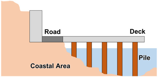
Figure 1.
Differences in pile length of offshore pier system.
Efforts to improve the constructability and technologies of offshore piers have been made. As a representative case, Shah et al. (2007) performed a structural performance experiment by connecting the flanges of precast girders with steel bolts for the continuity of a bridge. They analyzed factors that affected the fracture behavior and the resistance performance of the connection [26]. Yang and Kim (2014) examined bending performance when applying zinc-coated rebars to marine concrete structures [23]. Lee et al. (2019) studied composite structural behavior by preparing a full-scale specimen that simulated the connection between the precast bent cap combined with a river pier and precast girder [27]. Even though various studies have been conducted, most have focused on improving chloride attack resistibility and structural performance considering the marine environment. No study has been conducted to resolve construction errors in marine environment conditions [28,29,30].
Therefore, this study proposed a technology to solve construction errors using concrete suitable for marine structures. This modular system, which is named “Error Adjustment System”, could adjust the angle of construction error from the work process of installing the steel pipe file underground. In addition, it is configured in a form to facilitate the installation of the girder by correcting the angle of error in the horizontal direction. Material performances for developing an offshore pier system using UHPC were achieved, and the structural performance of the connection, a core part of the structure, was evaluated through experimental research.
2. Error Adjustment System
In this study, an attempt was made to develop an offshore modular pier system that enables the rapid and precise construction of bridges and piers in the marine construction environment and secures structural safety as well as sufficient durability for each construction phase.
An overview of the modular pier system is shown in Figure 2. The system consists of piles, connecting cores, copings, girders, and slabs. In addition, the substructure that plays a significant role in the error adjustment system consists of a steel pipe pile, connecting core, and pier coping, as shown in Figure 3. The connecting core and pier coping are concrete and inserted into the steel pipe pile. A curve is formed in the pocket between the connecting core and pier coping by adjusting the slope and level errors that may occur during pile driving in the field.

Figure 2.
Modular pier system.

Figure 3.
Concept of modular pier system.
Connections for the integrated behavior of the modular pier system were designed as shown in Figure 4 and Figure 5. Since tsunamis and waves caused by earthquakes may occur due to the nature of marine structures, special measures are required. Therefore, a circular plate was installed inside the pile for reinforcement against pullout, and an H-beam reinforced with studs was installed. After fixing the H-beam to the fixing pin of the circular steel plate, the connecting core was inserted into the pile, and the pier coping was placed.
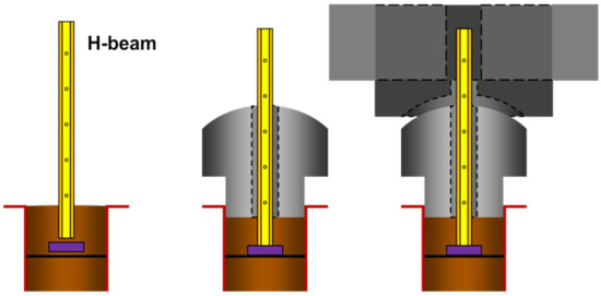
Figure 4.
Design of connections of cast-in-place systems.
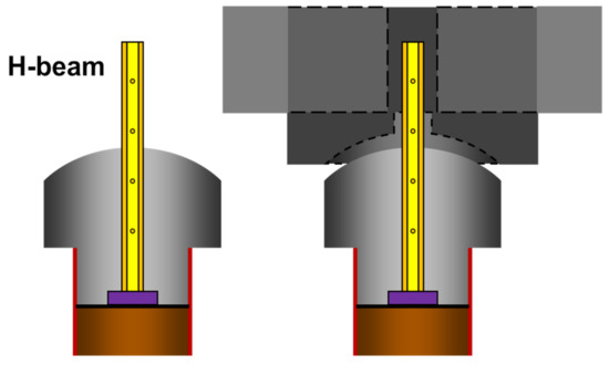
Figure 5.
Design of connections of precast systems.
Figure 4 shows the cast-in-place type, while Figure 5 shows the precast type. For the former, the modular system is completed by assembling the steel plates, H-beams, and connections at the site. For the latter, H beams and connections are produced, integrated into the factory, and placed on steel pipes at the site. Table 1 shows the benefits of each system.

Table 1.
Comparison of cast-in-place and precast types of system.
The system formed by the combination of these members can adjust vertical errors that occur during the pile installation process, and it can also correct horizontal errors, as shown in Figure 6. The girders manufactured in a dog-bone shape were installed from side to side, and curves were formed in the pier coping to enable fine adjustment from side to side. In addition, rebars were placed considering the lap splice length for the connection of girders to the pier coping so that structural safety could be secured.
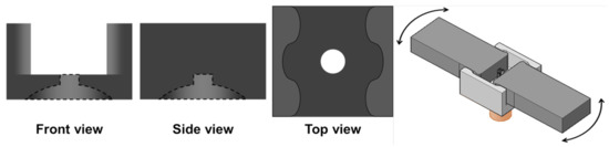
Figure 6.
Concept of pier coping.
Upon completing the vertical and horizontal work of girders, concrete grouting was performed for the system’s integrated behavior, as shown in Figure 7.
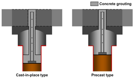
Figure 7.
The final stage of the modular pier system.
3. Securing UHPC Performance Suitable for the Marine Environment
3.1. Mix Proportion
Construction materials in this system require high workability and flowability because of the curved surfaces of these structural elements (Figure 4, Figure 5 and Figure 6). In addition, since the marine structures have been exposed to chloride attacks, outstanding durability is also needed in this system. Therefore, UHPC was applied to all components, including the connection core, pier coping, and girder, to satisfy every required performance.
UHPC was set as the target mix with the composition shown in Table 2 and Table 3. The premixed binder included ordinary Portland cement (OPC), silica fume, blast furnace slag, and filler. A filler, less than 30 μm, was used for beneficial effects such as filling in the voids between cement particles, enhancing strength during hydration, and increasing the fluidity of cement paste. Fine aggregate with 2.62 g/cm3 and an average particle size of 0.5 mm was used, and a filler of 30 μm or less was mixed with UHPC. In the case of steel fibers, to contribute to the tensile performance and crack resistance performance of UHPC, a product with a length of 13 mm, a diameter of 0.2 mm, and a tensile strength of 2000 MPa was used.
Table 2.
The mix proportions of UHPC.
Table 3.
Characteristics of materials for UHPC.
3.2. Compressive and Tensile Strengths
For the economy of the UHPC mix, the compressive and tensile strengths were measured according to the fiber content. To measure the compressive strength, Φ100 specimens were prepared, and to conduct a direct tensile strength test, dog-bone type specimens were prepared, as shown in Figure 8. Every specimen underwent steam curing for 3 days (90 °C, 100%), and those specimens were kept in normal conditions until 28 days (23 °C, 50%). The compressive and tensile experiments were conducted on samples aged 28 days. To induce cracking in the center of the specimen for the direct tensile test, a notch with a width of 2 mm and depth of 12.5 mm was introduced on both sides.
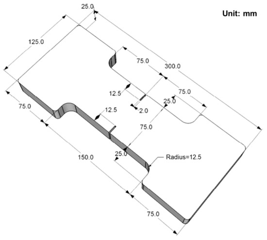
Figure 8.
The dog-bone type specimen for the measurement of direct tensile strength.
Figure 9 shows the failure shapes of the tensile strength specimens according to the steel fiber content (0.25 to 0.75%). Despite the notch formation in the dog-bone type specimens inducing tensile failure in the center, direct tensile failure did not occur at 0.25%. Tensile failure was induced at a content of 0.5% or higher, indicating that the performance of the steel fibers added to contribute to tensile performance was maximized.
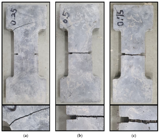
Figure 9.
Failure shapes according to the fiber content: (a) 0.25%; (b) 0.50%; (c) 0.75%.
Therefore, in this study, 30 specimens were prepared with contents of 0.50, 0.75, and 1.00%, and the compressive and tensile strengths were measured. Figure 10 and Figure 11 show the results of the 30 specimens excluding the maximum and minimum values. The experiments on compressive strength were conducted based on the ASTM C39M [31]. The compressive strength based on the fiber content was measured to be between 111.0 and 114.3 MPa, and there was no significant difference in compressive strength depending on the content. Generally, the bending strength of concrete mixed with steel fibers is dominantly affected by the fibers [32,33,34]. In other words, the compressive strength is directly affected by the microstructure formed by cement and mineral admixtures, and the impact of steel fibers is insignificant. The analysis of the tensile strength results in Figure 11 clearly shows that the tensile strength tended to increase as the fiber content increased. The average tensile strengths were 5.92 MPa at 0.50%, 7.20 MPa at 0.75%, and 9.15 MPa at 1.00%. For structures that require tensile performance, UHPC with a high content of metal fibers will be more suitable.
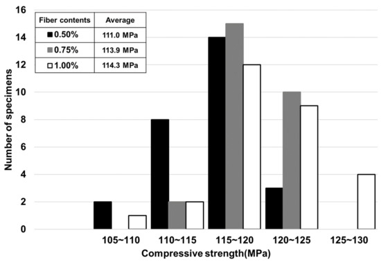
Figure 10.
Compressive strength results according to the fiber content.

Figure 11.
Direct tensile strength results according to the fiber content.
High tensile performance is not required for the developed modular system, and the crack resistance performance was considered more important. In other words, it was considered more important to attain performance that can prevent microcracks by adding steel fibers rather than improving tensile performance by adding a large number of steel fibers. Figure 12 shows the load and crack width at the notch measured during the experiment. At a fiber content of 0.50%, the load rapidly fluctuated during the initial cracks, thereby showing a brittle fracture. At 0.75%, the steel fibers added developed additional resistance performance after the initial cracks. This tendency was evident at a content of 1.00%. In other words, it was judged that a steel fiber content of 0.75% or higher is required for UHPC.
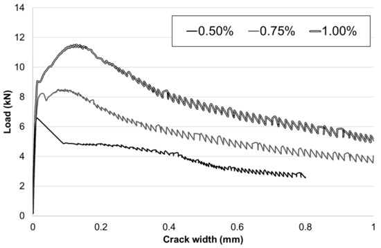
Figure 12.
Load–crack width results in the tensile strength test.
This system aims to be an economical mix for developing a modular system to secure minimal crack resistance performance. When considering the failure shapes of tensile test results, tensile failures occurred with a content of more than 0.5% as shown in Figure 12. In addition, when considering Figure 12, as tensile resistance beyond peak strength could be observed in the specimens of 0.75% and 1.0%. The flexibility of the specimen could be expected with more than 0.75% of steel fiber content. Therefore, the steel fiber content was set to 0.75% for the modular system, and UHPC, with a compressive strength of 113.9 MPa and tensile strength of 7.20 MPa, was used.
3.3. Chloride Attack Resistibility
The chloride attack resistibility of concrete was evaluated in accordance with ASTM C1202 [35]. The results are shown in Figure 13. The results for the three specimens were 12.51, 13.50, and 17.82 Coulombs, resulting in an average of 14.61 Coulombs. This indicates that excellent performance is secured because 100 Coulombs or less is classified into negligible grades that can ignore salt damage according to ASTM C1202. These results are attributed to the structural characteristics of UHPC. UHPC generally shows superior durability, including chloride attack resistibility [36,37]. It has been reported that very dense microstructures formed by various mineral admixtures secure the durability of UHPC. It was also confirmed that UHPC used in this study secured excellent chloride attack resistibility from the very dense structure, and that it is a concrete mix very suitable for the marine environment.
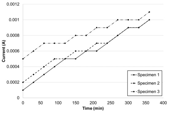
Figure 13.
Experimental results of chloride ion penetration.
4. Structural Performance Assessment
4.1. Specimen Preparation
The specifications of the error adjustment modular pier specimen to be developed in this study are shown in Figure 14. To assess the lateral load resistance performance of the connections of the specimen, girders were manufactured and placed in the reverse direction. With the girders placed at the bottom part of the pile at the top, lateral loading was applied to assess the performance of the modular specimen.
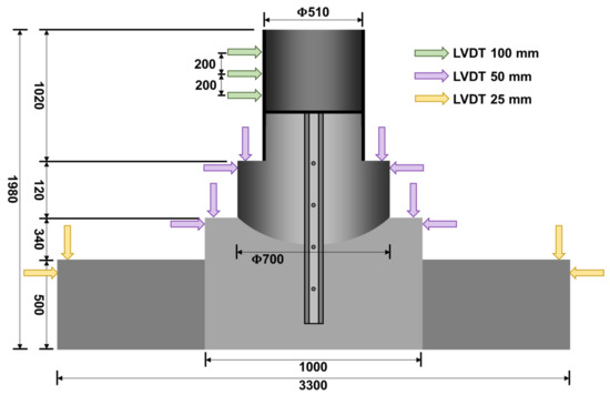
Figure 14.
Experimental setup with dimensions.
For the pile corresponding to a pier, a steel pipe pile with a thickness of 10 mm and a diameter of 510 mm was used. The connecting core was inserted into the pile, and a curvature (R = 500) was applied to the part where the coping was placed to enable plane error adjustment. The coping was designed to have a height of 840 mm and a width of 1000 mm on the side, while the girder had a height of 500 mm, 800 mm, and 1200 mm. To integrate the pile, connecting core, and coping and secure the overall structural stability of the pier, an H-beam with a width of 100 mm and height of 1410 mm, including shear connectors, was installed.
In the concrete production phase, UHPC was produced and poured through the prepared formwork of the coping, connecting core, and girder. Air-dry curing was then performed for 24 h. After demolding, high-temperature steam curing was performed for three days at 90 ± 5 °C to increase the strength. To implement the actual conditions, the produced members were assembled with the girders placed at the bottom and the bottom part of the pile at the top. Specimens were prepared by pouring concrete into the central connections of the pile, connecting core, coping, and girders, as shown in Figure 15.
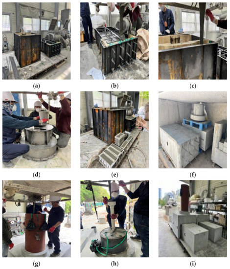
Figure 15.
Manufacturing process: (a) formwork; (b) girder; (c) coping; (d) connection core; (e) pouring concrete; (f) steam curing; (g) cast-in-place type; (h) precast type; (i) complete production.
4.2. Experimental Method
In this study, the lateral load resistance of the modular pier specimen was evaluated. To this end, loading was applied at a 1.5 mm/min rate using 1000 kN loading equipment. To measure the horizontal displacement and slope of the pile subjected to the lateral load, three displacement meters with a capacity of 100 mm were installed at 200 mm intervals, as shown in Figure 16. Four displacement meters with a capacity of 25 mm were installed to determine the occurrence of deformation during the lateral loading experiment, and eight with a capacity of 50 mm in the corner of the connection with a curved area between the pile head and the connecting core to examine the deformation that occurs during loading.
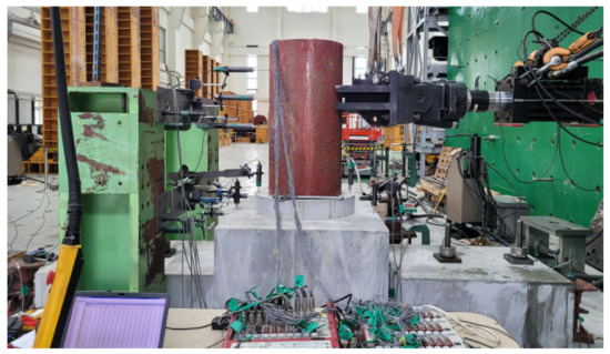
Figure 16.
Preparation for transverse resistance experiment.
In addition, strain gauges were attached at large intervals to the top and bottom of the core beam installed in the center between the pile head and the pile, and 15 strain gauges were attached at 30 mm intervals to the center, where significant local bending occurs, to measure the deformation during loading.
4.3. Experimental Results
During the lateral load resistance experiment, the load did not vary significantly after the maximum, and only the displacement continued to increase. As the pile column tilted, the head joint of the actuator was bent, and the experiment was terminated due to the concern that load transmission in the straight line direction would not occur. The overall experimental results show that the precast and cast-in-place types perform similarly. In other words, the modular pier system types developed in this study have similar performance, and it is expected that the types suitable for the on-site work environment can be selected and utilized.
4.3.1. Deflection in Girder
Figure 17 shows the displacement in the girder. It can be seen that a displacement of 0.5 mm or less occurred. In the specimen setting process, the girders were set to be fixed entirely, and it was judged that deformation hardly occurred at that point.
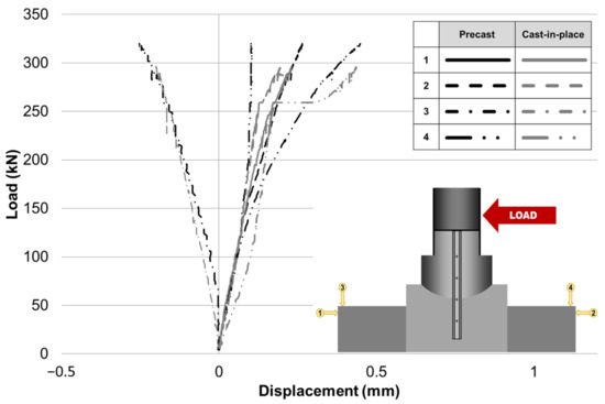
Figure 17.
Experimental results of the girder.
4.3.2. Deflection in Connection
Figure 18 and Figure 19 show the pier coping and connection core displacement, respectively. Under loading, the displacement of the pier coping was approximately 1 mm. This result indicates that the lateral load has no significant impact on the girder in the modular system. Meanwhile, a displacement of approximately 8 mm was recorded at the fourth measurement position of the connection core.
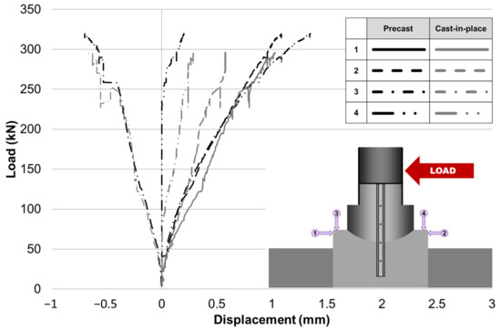
Figure 18.
Experimental results of pier coping.
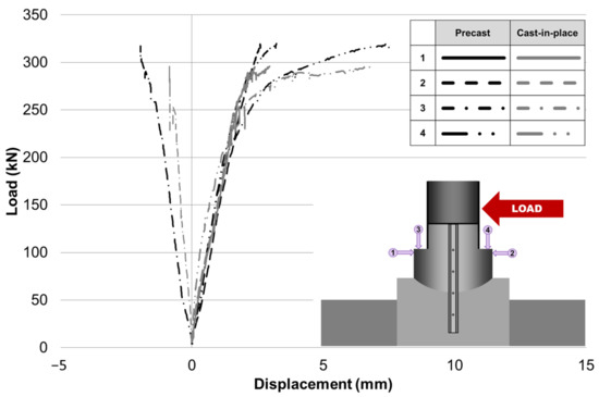
Figure 19.
Experimental results of connection core.
Figure 20 shows the deformation of the connection core. As the core part rotated along the curvature of the connection core, relatively large deformation occurred based on the curvature of the core. At the final time, displacement of approximately 23 mm was recorded. This result differs from the deformation (8 mm) recorded at the fourth position in Figure 19. Figure 21 shows the measurement process of the displacement meter during the experiment. As the connection core rotated, a slope was formed on the measurement surface of the displacement meter, and errors in the measurement equipment occurred along the slope. However, this study experimented by placing the entire modular system in the reverse direction. When the actual structure is constructed and used, it is judged that the self-weight of upper structures, such as girders, will fill the gap between the connection core and pier coping. Therefore, based on the results in Figure 18 and Figure 19, the effect of the lateral load applied from the outside on the entire modular system was judged to be insignificant, and it can be determined that the safety at the joint is confirmed.

Figure 20.
Deformed shapes of connection core.
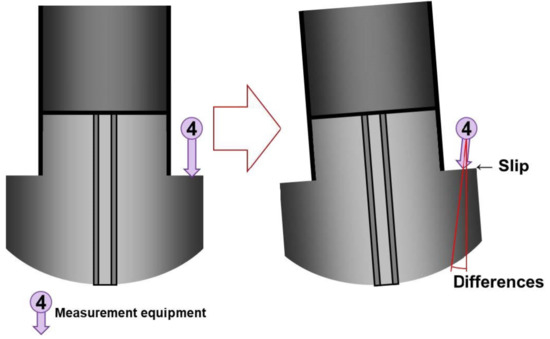
Figure 21.
Difference between the connection core and the fourth displacement meter measurement position (see Figure 19).
4.3.3. Deflection of Pile
Figure 22 shows the deformation measured in the pile, and Figure 23 shows the deformation angle. The maximum load and displacement were measured to be 319.95 kN and 25.81 mm for the precast specimen and 296.04 kN and 23.01 mm for the cast-in-place specimen, respectively. In other words, the precast type exhibited approximately 8% higher strength. At 296 kN, the maximum load of the cast-in-place type, the column angle of the cast-in-place type was 1.68 degrees, but that of the precast type was 1.21 degrees, confirming that the deformation of the precast type was smaller under the same load.
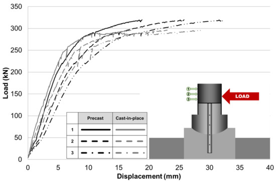
Figure 22.
Experimental results of the pile.
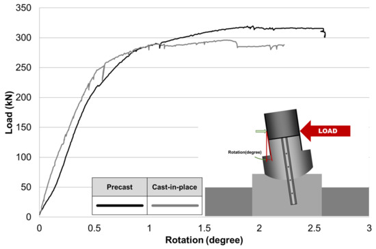
Figure 23.
Experimental results of pile considering the rotation.
Meanwhile, the design bending strength of the corresponding modular system was calculated to be 439.2 kN-m. From the perspective of the maximum bending moment, the maximum bending moments can be obtained as 518.3 kN-m for the precast specimen and 479.6 kN-m for the cast-in-place specimen. These values are 118% and 109% of the design bending strength, indicating that sufficient load-carrying capacity is secured for both the precast and cast-in-place specimens.
4.3.4. Crack
When the behavior of the offshore modular pier was evaluated, there were no cracks in the bottom girder and pier. Cracks, however, occurred in some parts of the curved area where behavior was also confirmed with the naked eye. Figure 24 shows the cracks identified in the curved area. Crack characteristics were observed in the lower part of the connecting core, in the opposite direction of the loading point, as the load was transmitted locally. Unlike typical concrete, however, it was found that the bridging effect of steel fibers inhibited the growth of cracks despite continuous load transfer [23]. This phenomenon indicates that the high compressive strength and crack resistance performance of UHPC inhibited fracturing at the bottom of the connecting core.
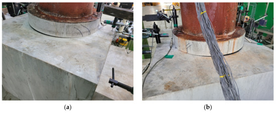
Figure 24.
Crack shapes in connections: (a) precast specimen; (b) cast-in-place specimen.
5. Conclusions
This study was conducted to develop modular technology that can be used in the marine environment. A technology to control horizontal and vertical errors during construction was proposed by creating a new type of connecting core. The results of this study can be summarized as follows.
A modular system was constructed using UHPC, which is suitable for the marine environment. A fiber content to prevent brittle failure was derived, with a mix containing a fiber content of 0.75% determined after considering the economic feasibility of the modular system. Consequently, the mix with a compressive strength of 113.9 MPa and tensile strength of 7.20 MPa was used. In addition, 14.61 Coulombs was confirmed as the chloride attack resistibility for the utilization of the system in the marine environment, thereby attaining very high durability. Therefore, UHPC applied in this study proved to be a very suitable concrete mix for use in the marine environment.
Minor deformation was observed in the girder and pier when the lateral load resistance was examined. In the connection core, the tendency to rotate along the curvature of the core was confirmed as the lateral load was applied, and a gap of approximately 20 mm was confirmed. However, the experiment in this study was performed by installing the members in the reverse direction. In a situation where the actual structure is used, it is judged that the self-weight of the girder and bottom plate will fill the gap. Therefore, it is judged that the safety of the girder and joint of the modular system is secured by applying the lateral load.
The developed technology was divided into precast and cast-in-place types according to the production method. The results of the lateral load resistance performance experiment showed that the performance of the precast and cast-in-place types met the criterion. Compared to the design bending strength, maximum bending moments of approximately 118% and 109% were observed for the precast and cast-in-place types, respectively, confirming that sufficient load-carrying capacity was achieved. Therefore, both methods secured structural safety, and the more suitable method can be selected and used considering the environmental conditions of construction.
For the completion of this system, many challenging problems remain to be solved. These include reinforcement details considering the economic design and section properties of structural members. In addition, difficulties arising from fieldwork should also be considered, such as the installation of connection core, the operation statute of error adjustment, and so on. This system could be expected to be completed following further research considering complex environmental influences.
Author Contributions
Conceptualization, K.L. and K.K. (Kyungtaek Koh); methodology, J.K. and G.R.; investigation, K.L.; data curation, K.L., J.K., G.R., and K.K. (Kyongchul Kim); writing—original draft preparation, K.L.; writing—review and editing, K.L. and K.K. (Kyongchul Kim); supervision, K.K. (Kyungtaek Koh); funding acquisition, K.K. (Kyungtaek Koh). All authors have read and agreed to the published version of the manuscript.
Funding
Research for this paper was carried out under the KICT Research Program (project no. 20230167-001, Development of Commercialization Technologies for Long-Life Modular Marine Bridge System with SUPER Concrete) funded by the Ministry of Science and ICT.
Data Availability Statement
The data could be available from the corresponding author upon reasonable request in special conditions.
Conflicts of Interest
The authors declare no conflict of interest.
References
- Park, S.-S.; Kim, M.-W. Evaluate the Concrete mix by Type Accelerated Corrosion Test and Chloride Penetration Analysis with Artificial Seawater Cyclic Wet and Dry Condition. J. Korean Recycl. Constr. Resour. Inst. 2013, 1, 211–218. [Google Scholar] [CrossRef]
- Lee, B.-Y.; Kwon, S.-J.; Kang, S.-T. Analytical Estimation of the Performance of Marine Concrete with Mineral Admixture. J. Korean Recycl. Constr. Resour. Inst. 2015, 3, 301–306. [Google Scholar] [CrossRef][Green Version]
- Hong, S.-I.; Lee, H.-G.; Moon, D.-Y. Evaluation of Pore Size Distribution and Chloride Diffusion in Steel Fiber Reinforced Mortar depending on Supplementary Cements. J. Korea Concr. Inst. 2019, 31, 147–152. [Google Scholar] [CrossRef]
- Peng, R.-X.; Qiu, W.-L.; Teng, F. Research on performance degradation analysis method of offshore concrete piers in cold regions. Ocean Eng. 2022, 263, 112304. [Google Scholar] [CrossRef]
- Li, X.; Shui, Z.; Yu, R.; Wang, X. Magnesium induced hydration kinetics of ultra-high performance concrete (UHPC) served in marine environment: Experiments and modelling. Constr. Build. Mater. 2019, 224, 1056–1068. [Google Scholar] [CrossRef]
- Behnam, A.; Sharif, T.S. Combined Effects of Saltwater and Water Flow on Deterioration of Concrete under Freeze–Thaw Cycles. J. Cold Reg. Eng. 2011, 25, 145–161. [Google Scholar] [CrossRef]
- Bao, J.; Wei, J.; Zhang, P.; Zhuang, Z.; Zhao, T. Experimental and theoretical investigation of chloride ingress into concrete exposed to real marine environment. Cem. Concr. Compos. 2022, 130, 104511. [Google Scholar] [CrossRef]
- Yoon, Y.S.; Ryu, H.S.; Lim, H.S.; Koh, K.T.; Kim, J.S.; Kwon, S.J. Effect of grout conditions and tendon location on corrosion pattern in PS tendon in grout, Constr. Build. Mater. 2018, 186, 1005–1015. [Google Scholar] [CrossRef]
- Farin, M.; Moulin, E.; Chehami, L.; Benmeddour, F.; Nicard, C.; Campistron, P.; Bréhault, O.; Dupont, L. Monitoring saltwater corrosion of steel using ultrasonic coda wave interferometry with temperature control. Ultrasonics 2022, 124, 106753. [Google Scholar] [CrossRef]
- Gollop, R.S.; Taylor, H.F.W. Microstructural and microanalytical studies of sulfate attack. V. Comparison of different slag blends. Cem. Concr. Res. 1996, 26, 1029–1044. [Google Scholar] [CrossRef]
- Poursaee, A.; Hansson, C.M. Reinforcing steel passivation in mortar and pore solution. Cem. Concr. Res. 2007, 37, 1127–1133. [Google Scholar] [CrossRef]
- Vieira, D.R.; Moreira, A.L.R.; Calmon, J.L.; Dominicini, W.K. Service Life Modeling of a Bridge in A Tropical Marine Environment for Durable Design. Constr. Build. Mater. 2018, 163, 315–325. [Google Scholar] [CrossRef]
- Choi, J.-W.; You, Y.-J.; Jeong, Y.-J.; Kwon, S.-J.; Kim, J.-H.J. Micro-silica Mixed Aqua-epoxy for Concrete Module Connection in Water: Part 2—Structural Application and Evaluation. J. Korea Concr. Inst. 2015, 27, 29–35. [Google Scholar] [CrossRef]
- Chen, Z.; Li, S.; Zhou, J.; Xu, R.; Dai, S. Flexural behavior of GFRP bars reinforced seawater sea sand concrete beams exposed to marine environment: Experimental and numerical study. Constr. Build. Mater. 2022, 349, 128784. [Google Scholar] [CrossRef]
- Zhang, K.; Zhang, Q.; Xiao, J. Durability of FRP bars and FRP bar reinforced seawater sea sand concrete structures in marine environments. Constr. Build. Mater. 2022, 350, 128898. [Google Scholar] [CrossRef]
- Li, S.; Zhu, D.; Guo, S.; Xi, H.; Rahman, M.Z.; Yi, Y.; Fu, B.; Shi, C. Static and dynamic tensile behaviors of BFRP bars embedded in seawater sea sand concrete under marine environment. Compos. Part B Eng. 2022, 242, 110051. [Google Scholar] [CrossRef]
- Kang, S.-H.; Kang, H.U.; Lee, N.K.; Kwon, Y.H.; Moon, J.H. Development of cementless ultra-high performance fly ash composite (UHPFC) using nucleated pozzolanic reaction of low Ca fly ash. Cem. Concr. Compos. 2022, 132, 104650. [Google Scholar] [CrossRef]
- Lin, Y.; Yan, J.; Wang, Z.; Zou, C. Theoretical models and reliability assessment of steel-UHPC-steel composite beams in offshore structures. Ocean. Eng. 2023, 271, 113739. [Google Scholar] [CrossRef]
- Wang, Z.; Yan, J.; Lin, Y.; Fan, F. Influence of shear connectors on the ultimate capacity of steel-UHPC-steel slabs subjected to concentrated loads. Eng. Struct. 2021, 231, 111763. [Google Scholar] [CrossRef]
- Yan, J.-B.; Guan, H.; Wang, T. Steel-UHPC-steel sandwich composite beams with novel enhanced C-channel connectors: Tests and analysis. J. Constr. Steel Res. 2020, 170, 106077. [Google Scholar] [CrossRef]
- Dachollom, G.L.; Hejazi, F.; Yusuf, B. Development of Ultra High-Performance Fiber reinforced concrete barge for 5 MW wind turbine. Structures 2023, 53, 1349–1368. [Google Scholar] [CrossRef]
- Kim, K.-C.; Yang, I.-H.; Joh, C. Effects of Single and Hybrid steel Fiber Lengths and Fiber Contents on the Mechanical Properties of High-Strength Fiber-Reinforced Concrete. Adv. Civ. Eng. 2018, 2018, 7826156. [Google Scholar] [CrossRef]
- Yang, I.-H.; Kim, K.-C. An Experimental Study on Flexural Behavior of Beams Reinforced with Zinc-Coated Rebar. J. Korea Concr. Inst. 2014, 26, 299–306. [Google Scholar] [CrossRef]
- Lin, Y.; Yan, J.; Wang, Z.; Zou, C. Effects of steel fibers on failure mechanism of S-UHPC composite beams applied in the Arctic offshore structure. Ocean. Eng. 2021, 234, 109302. [Google Scholar] [CrossRef]
- Vincler, J.P.; Sanchez, T.; Turgeon, V.; Conciatori, D.; Sorelli, L. A modified accelerated chloride migration tests for UHPC and UHPFRC with PVA and steel fibers. Cem. Concr. Res. 2019, 117, 38–44. [Google Scholar] [CrossRef]
- Shah, B.N.; Sennah, K.; Kianoush, M.R.; Tu, S.; Lam, C. Experimental Study on Prefabricated Concrete Bridge Girder-to-Girder Intermittent Bolted Connections System. J. Bridg. Eng. 2007, 12, 570–584. [Google Scholar] [CrossRef]
- Lee, H.; Min, J.; Chung, W. Full-Scale Testing of Precast Concrete Bridge Using Internal Connector in Negative Moment Region. Adv. Civ. Eng. 2019, 2019, 6309859. [Google Scholar] [CrossRef]
- Jarek, A.; Dos Santos, A.T.; Bragança, M.O.G.P.; Pinkoski, I.M.; Neri, M.A.T.; Diniz, J.H.O.T.; Gomes, R.A.N. Experimental and numerical investigations to evaluate the structural integrity of concrete beams exposed to an aggressive coastal environment. Structures 2022, 37, 795–806. [Google Scholar] [CrossRef]
- Cramer, S.D.; Covino, B.S., Jr.; Bullard, S.J.; Holcomb, G.R.; Russell, J.H.; Nelson, F.J.; Laylor, H.M.; Soltesz, S.M. Corrosion prevention and remediation strategies for reinforced concrete coastal bridges. Cem. Concr. Compos. 2002, 24, 101–117. [Google Scholar] [CrossRef]
- De Domenico, D.; Lamberto, G.; Messina, D.; Recupero, A. Seismic vulnerability assessment of reinforced concrete bridge piers exposed to chloride-induced corrosion. Procedia Struct. Integr. 2023, 44, 633–640. [Google Scholar] [CrossRef]
- ASTM C39M-21; Standard Test Method for Compressive Strength of Cylindrical Concrete Specimens. ASTM International: West Conshohocken, PA, USA, 2021.
- Deng, Y.; Yan, C.; Niu, P. Hysteretic model of reinforced concrete bridge piers based on earthquake damage and corrosion from saline soil. Soil Dyn. Earthq. Eng. 2023, 166, 107732. [Google Scholar] [CrossRef]
- Shweta, P.; Kavilkar, R. Study of Flexural Strength in Steel Fibre Reinforced Concrete. Int. J. Recent Dev. Eng. Technol. 2014, 2, 13–16. [Google Scholar]
- Zheng, Y.; Wu, X.; He, G.; Shang, Q.; Xu, J.; Sun, Y. Mechanical Properties of Steel Fiber-Reinforced Concrete by Vibratory Mixing Technology. Adv. Civ. Eng. 2018, 2018, 9025715. [Google Scholar] [CrossRef]
- ASTM C1202-22; Standard Test Method for Electrical Indication of Concrete’s Ability to Resist Chloride Ion Penetration. ASTM International: West Conshohocken, PA, USA, 2022.
- Ravichandran, D.; Prem, P.R.; Kaliyavaradhan, S.K.; Ambily, P.S. Influence of fibers on fresh and hardened properties of Ultra High Performance Concrete (UHPC)—A review. J. Build. Eng. 2022, 57, 104922. [Google Scholar] [CrossRef]
- Ghasemzadeh Mosavinejad, S.H.; Langaroudi, M.A.M.; Barandoust, J.; Ghanizadeh, A. Electrical and microstructural analysis of UHPC containing short PVA fibers. Constr. Build. Mater. 2020, 235, 117448. [Google Scholar] [CrossRef]


Disclaimer/Publisher’s Note: The statements, opinions and data contained in all publications are solely those of the individual author(s) and contributor(s) and not of MDPI and/or the editor(s). MDPI and/or the editor(s) disclaim responsibility for any injury to people or property resulting from any ideas, methods, instructions or products referred to in the content. |
© 2023 by the authors. Licensee MDPI, Basel, Switzerland. This article is an open access article distributed under the terms and conditions of the Creative Commons Attribution (CC BY) license (https://creativecommons.org/licenses/by/4.0/).