Abstract
Additive manufacturing (AM) with concrete, also known as concrete 3D printing, is one of the most interesting approaches for disrupting the construction industry and is currently subject to numerous research activities worldwide. AM has great potential to decrease labour costs and increase the material efficiency and geometric complexity of non-standardised building components. Although prior investigations have shown various fields of application for AM with concrete, the full potential with respect to different structural component types has not been covered yet. With this paper, an up-to-date review of fabrication strategies for the main structural components, (1) walls, (2) columns, (3) slabs, and (4) beams, is provided to identify trends and existing challenges. Therefore, firstly, AM methods and their underlying principles and characteristics for concrete components are presented, and secondly, fabrication strategies for each AM method are shown. The investigation uncovers different AM strategies (direct part vs. indirect “permanent formwork”; in situ, on-site, or off-site), which are currently being used. As a result, future applications of AM will require a hybrid manufacturing strategy combining conventional and additive manufacturing to fully explore its potential.
1. Introduction
Concrete is not only one of the most widely used building materials in the world, it is also one of the main contributors to climate change. It is estimated that 8% of global CO2 emissions are caused by cement production [1]. Due to continuous population growth, urbanisation, and an ageing building infrastructure, the current cement consumption of 4.1 trillion tonnes per year (2022) could increase by 12–23% by 2050 compared to 2014 [2,3]. In light of these figures and the Paris Climate Agreement’s goal of limiting the global temperature increase to 1.5 °C, the construction industry is faced with the challenge of drastically reducing cement consumption [4]. With the aim of reducing excessive material use and minimising waste, current concrete-based construction methods need to be continuously challenged. The construction industry can no longer avoid investing in productivity-enhancing options in the face of a growing shortage of skilled workers and the need to catch up on investment in housing and infrastructure [5].
According to a widely cited study by the McKinsey Global Institute, global labour productivity in the construction sector has grown by an average of only 1 per cent per year over the past two decades, while the global economy as a whole has grown by 2.8 per cent and the manufacturing sector by 3.6 per cent [6]. By eliminating manual formwork and using robotic-based concrete 3D printing for structural components in construction, the proportion of labour-intensive processes could be reduced. This can lead to an increase in labour productivity [7].
Formwork has always been critical in producing reinforced concrete structures. Together with the reinforcement and the concrete work, it determines the construction process, has a decisive influence on the design and surface finish of the concrete components, and is required for almost every component shape. For reasons of economy and quality, concrete construction is almost exclusively carried out using system formwork, which can be repeatedly erected and quickly removed.
The use of concrete-based additive manufacturing methods (known as “concrete 3D printing”) offers an alternative construction method that not only allows concrete to be used in a resource-efficient way but also eliminates the need for formwork as much as possible by constructing the structure directly from a digital model. This not only offers the prospect of far-reaching productivity and quality improvements but also shape-optimised, non-standardised components [8,9,10]. A major benefit of the technology is the ability to fabricate complex, shape-optimised components at lower cost and in less time, resulting in a reduced environmental footprint through efficient use of materials [11].
Several literature reviews have explored the integration of concrete additive manufacturing into the construction industry so far. Some reviews have focused on the overall implementation to highlight the general potential, future challenges, or barriers of AM [12,13,14,15,16]. Others have focused more on the differences between the AM methods or their underlying material properties [17,18,19]. Furthermore, reviews have been conducted to investigate developments in printing systems [20,21], extruder design [22,23], or reinforcement strategies [24,25]. Additionally, there are comprehensive studies on the digital planning processes for 3D printing [26], possible fields of application [9,27,28,29], and the impact on the construction market [30].
1.1. Current Situation and Problem Statement
Stakeholders in the construction industry have already acknowledged that concrete additive manufacturing will bring a fundamental change to the existing principles of construction. In particular, formwork manufacturers’ involvement in this new technology can be seen as indicative of its disruptive nature [31].
Over the past few years, the number of 3D-printed buildings worldwide has increased steadily. Well-known 3D-printed buildings are spread around the world and are located in Dubai (UAE) [32], Eindhoven (The Netherlands) [33], Westerlo (Belgium) [34], and Austin, Texas (USA) [35]. In Germany, the “first 3D-printed single-family house” was built in Beckum in 2021 [36], followed by the “first 3D-printed five-unit apartment building” in Wallenhausen [37]. However, concrete 3D printing is still in its infancy. This can be seen from a numeric comparison with the number of “conventional” new homes built in Germany in 2021: around 293,000 “conventional” homes compared to 5 “3D printed” homes [38].
Although media reports suggest that 3D-printing technology is ready for the market, the field of application is mainly focused on pure compression-stressed and unreinforced concrete walls using extrusion methods [39]. In particular, the technology is still at an early stage of development, with the integration of reinforcement remaining an unresolved process challenge. In the aforementioned 3D-printed buildings, bending-stressed components (slabs, beams) are often produced using conventional formwork-based construction methods (in situ or precast) [39].
Thereby, it can be assumed that, due to the diversity of construction projects, extrusion-based concrete additive manufacturing will probably only be one way to integrate AM into the construction industry. What is more, buildings might not be printed in total but in individual components. Therefore, it is not only worth considering alternative concrete additive manufacturing processes (e.g., particle bed printing or shotcrete printing) but also thinking about different strategies to fabricate on a component level. To the authors’ best knowledge, no published work has focussed, collected, and compared exiting fabrication strategies for concrete components using different additive manufacturing methods.
1.2. Aim and Scope of This Paper
This paper aims to present the applicability and possible fabrication strategies of concrete additive manufacturing to integrate concrete additive manufacturing on the component level. In order to do this, the article will be divided into two main parts.
In the first part, the basic differences, methods, and processes of the additive manufacturing of concrete will be explained. This includes presenting the fundamental differences between additive and conventional (formative or subtractive) construction methods and comparing the three main types of concrete additive manufacturing.
In the second part, the principles and characteristics identified are used to investigate the applicability of concrete additive manufacturing to the construction industry, distinguishing between different types of structural components. Finally, trends, potentials, and challenges will be derived from the fabrication strategies under review, and the need for further research will be identified.
2. Review of Concrete Additive Manufacturing (CoAM)
2.1. Classification of AM Processes
It is helpful to consider the systematics of manufacturing processes as a whole in order to classify “additive manufacturing” and distinguish them from “conventional construction” [40]. According to DIN 8580, manufacturing include “all processes for the manufacturing of geometrically defined solids. They include the processes for obtaining initial forms from a formless state, for modifying this form, and for changing the material properties” [41]. Based on the classification of the “Status Report of the RILEM Technical Committee 276-DFC Digital fabrication with cement-based materials” [42] and the corresponding publication by Buswell et al. [43], manufacturing processes can basically be divided into three main groups:
- Formative manufacturing processes
- Subtractive manufacturing processes
- Additive manufacturing processes.
In conventional construction, the concrete components are given their shape by the formwork. This formwork is used to create the solid body (component) from the material (cast concrete), which is initially formless. In subtractive processes, the geometry is created from a given initial solid body by removing or dividing manufacturing processes. For this purpose, milling, cutting, and grinding processes can be used, among others, to remove unwanted material from an initial solid body. The counterpart to subtractive manufacturing is additive manufacturing, which is the focus here. According to DIN 8580 and DIN EN ISO/ASTM 52900, additive manufacturing is defined as “a process of joining materials to make parts form 3D model data, usually layer by layer, as opposed to subtractive and forming manufacturing methodologies” [41,44]. In additive manufacturing, the geometry is not built up by the removal of material [subtractive] or by the solidification of liquid material in a mould/formwork [formative] but by the application of material layer by layer [additive].
2.2. Characteristics of AM Methods
In general, there are three different additive manufacturing methods for concrete. Selective-binding-in-a-particle-bed methods are contrasted with the deposition methods of extrusion and its particular form of spraying. The particle-bed-based methods are further subdivided into three processes (see Figure 1).
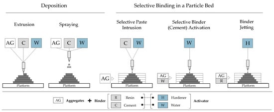
Figure 1.
Schematic overview of concrete additive manufacturing methods; based on [11,45].
The extrusion method is the most commonly used process for concrete additive manufacturing [26,46]. This method is based on the controlled deposition of a strand of material that is plastically deformable along a defined printing path. In a further development of the conventional shotcrete process, concrete is applied robotically in layers and with the addition of compressed air and a curing accelerator with robot support. In selective binding methods, the component structure is always built up by means of a bed of particles. The features and characteristics of each of these methods are described in more detail in the following sections.
2.2.1. Extrusion-Based CoAM
Extrusion-based concrete additive manufacturing methods (in the following “extrusion”) are commonly known as concrete (3D) printing. In 2011, concrete 3D printing was developed at Loughborough University [47]. It involves a pre-mixed material being freely deposited (and vertically layered) as filaments along a defined print path through a robot-guided nozzle. However, the origins of extrusion can be traced back to “Contour Crafting”, developed by Bekrokh Koshnevis at the University of Southern California. He demonstrated the basic feasibility of additive manufacturing for the construction industry using a concrete wall as a “permanent” formwork as an example [48,49].
Extrusion can be considered according to two main characteristics: (1) the “degree of deformation allowed after extrusion” and (2) the size of the filaments (cross-sectional area and ratio of width to height) [50]. One way is the extrusion of very stiff material, where the final filament shape is the same as the nozzle geometry. Alternatively, slight deformation can occur after the material leaves the nozzle, resulting in the extrusion of a free-flowing material. A very fine filament can be used to achieve high print resolution. In contrast, coarser filaments give a faster printing speed. According to [50], three deposition categories can be distinguished:
- Fine: filament width or diameter up to 10 mm [51]
- Medium: filament width < 50 mm [49]
- Coarse: filament width > 100 mm [52].
Typically, the printing material fulfils several rheological requirements [53,54]: (1) the material should be able to be pumped from the mixing unit to the nozzle; (2) it should be able to be extruded from the nozzle in a controlled manner, e.g., by means of an extruder screw; and (3) it should be dimensionally stable after it has left the nozzle. These requirements place demands on the rheology that are in part contradictory: On the one hand, good “extrudability” is achieved by a kneadable, earth-moist material consistency, which would have limited pumpability [55]. On the other hand, the requirement for rapid strength development and dimensional stability of the individual layers for rapid structure build-up leads to the risk of premature material solidification and, thus, a “cold joint”.
Therefore, the best practice would be to always print “fresh in fresh”, which will counteract the dimensional stability after exiting the nozzle. Consequently, there are optimal time windows for applying the next layer (so-called “open time” or “layer cycle time”) [54]. Various approaches have been taken to improve the interlocking of the layers [56,57].
Matching the material technology to the manufacturing process is one of the most important features of the extrusion process, if not for all CoAM processes. The extrusion process is influenced by a large number of process, material, and machine parameters, including the nozzle diameter, flow rate, or robot speed. In particular, robot speed and flow rate must be matched. Otherwise, discontinuous material application (“under-” or “over-extrusion”) will occur [54]. There are further differences in the type of extruder (piston or screw) and in the material feeding/delivery system, which are not discussed here [23].
In addition to the design of the material supply system (see Figure 2–green), consisting of mixing and pump units and the controlling system (see Figure 2–blue), a “printing system” (manipulator or more commonly “robot”) is required for the controlled guidance of the nozzle (see Figure 2–red). Three-axis gantry systems or industrial robots are the most common robot systems (also called manipulators, positioning systems, or simply robots) [23,58,59,60]. Industrial robots have the advantage that the build volume is not linked to the size of the robot itself. However, this requires frequent repositioning [58]. Compared to gantry systems, they are more flexible with 6 instead of 3 degrees of freedom but more difficult to control. Alternative approaches are similar to the operation of classic truck-mounted concrete pumps or tower cranes and can be categorised as boom robots [58]. New technical solutions extend the current functionalities of the robots. For on-site use, robotic systems are, for example, mounted on a rail system or fitted with a crawler chassis [61].
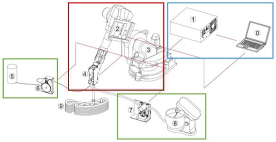
Figure 2.
Components of the robot-based, concrete additive manufacturing system as described in [62]: (0)—System command, (1)—Robot controller, (2)—Printing controller, (3)—Robotic arm, (4)—Printhead, (5)—Accelerating agent, (6)—Peristaltic pump for the accelerating agent, (7)—Peristaltic pump for premix, (8)—Premix mixer device, (9)—3D-printed object. Here the material is first mixed and brought together at the print head (variant b). Coloured rectangles are not in the original version. Reprinted with permission from [62].
The shape of the filament is, therefore, significantly influenced by the nozzle geometry (round or rectangular), the nozzle diameter (a few millimetres to a few centimetres), the application angle (0, 45, or 90 degrees), or additional aids (extension of the nozzle tip or lateral trowels) [23,54,63]. According to [23], the round nozzle geometry is preferred to the rectangular one, and the material is usually extruded in a vertically downward direction (0 degrees) so that the shape of the filament is characterised by rounded outer contours. Vertical application (0 degrees “plumb”) has the advantage that the nozzle does not have to rotate for curved paths. Horizontal (90 degrees) application with a leading nozzle would require the print head to rotate around a fourth axis for curved paths (see Figure 3).
Usually, for extrusion, very fine-grained material mixes (more like mortar than concrete) are used. This makes the structure susceptible to shrinkage cracking or creep deformation [64]. However, a coarser aggregate will also require a larger nozzle cross-section. More complex, filigree geometries are possible with smaller nozzle diameters. Other differences with regard to the print head include the use of “trowels” mounted on the print head to produce smooth surfaces or the length of the nozzle tip to allow, for example, reinforcement bars to be pre-integrated [49].

Figure 3.
From left to right: examples of different print head designs: US company We Print Homes with a BOD-2 gantry printer including side trowels and a rectangular nozzle (left) [65], with permission by Rob Portil/ We Print Homes; French company XtreeE with a round nozzle (centre) [66], with permission from Alban Mallet/XtreeE; Dutch company CyBe with an extended “lance” and a round nozzle (right) [67], with permission from Daan Roosendaal/CyBe Construction.

2.2.2. Spraying-Based CoAM
Unlike extrusion, spray-based concrete AM involves the direct addition of compressed air just before the material is applied [11,68]. The process is based on the 100-year-old conventional sprayed concrete technology, except that the material is applied fully automated, with a smaller nozzle distance to the application point (15–20 cm) and at lower pressures (1–2 bar) [64,69]. Analogous to the extrusion process, the material is first delivered to the nozzle by a pumping unit in a dense flow. Inside the nozzle, the material is accelerated by means of compressed air, atomised, and applied in a layer-by-layer fashion (called the wet-spraying process) [70].
The development of spraying-based processes for the 3D printing of concrete can be traced back to a group of researchers from the Technical University of Braunschweig [68,71]. In 2016, the so-called Digital Building Fabrication Laboratory (DBFL) was put into operation at the Institute for Structural Design (ITE) of the TU Braunschweig for the implementation of the Shotcrete 3D Printing (SC3DP) process. For a comprehensive description of the DBFL, see [11,72]. The fabrication area essentially consists of two units composed of different components, which cover a “printable” area of 15 m × 7 m × 3 m (L × W × H) [11]. The first unit is made up of a 6-axis industrial robot coupled to a 3-axis gantry. The industrial robot, which can be equipped with various end effectors (e.g., spray nozzle, welder), can move freely in the entire work area. It thus represents the additive work unit of the DBFL. The second unit is another gantry equipped with a 5-axis CNC-controlled milling and sawing device. It represents the subtractive unit of the DBFL. Currently, a printing speed (spraying capacity) of approximately 1 m³ per hour can be achieved in the DBFL [73]. Hardening accelerators can be added to the nozzle to increase the early strength and printing speed [74].
Due to the compressed air accelerated material application, the printed geometries show a very good bond between the individual layers. This counteracts the formation of “cold joints” [72]. The geometric properties of the layers are controlled by the speed of the robot and the distance of the nozzle from the point of application. For vertical application, layer thicknesses of 1 cm and layer widths of 12 cm with a nozzle distance of 15 cm have been found to be practical [73]. Currently, online tracking control is being investigated for precise layer build-up and continuous target/actual comparisons [75]. The characteristics of the spraying process also allow for transitions from the vertical to the horizontal plane (gradual transition printing) [71]. Alternatively, it is possible to print against existing structures (concrete or reinforcing) using different printing angles [76] (see Figure 4).
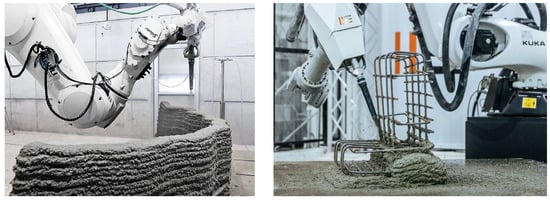
Figure 4.
Examples for the spraying-based CoAM Process: (left): Concrete supports Reinforcement [73], © ITE, TU Braunschweig, (right): Reinforcement supports Concrete [77], with permission from Alexander Türk/Aeditive.
A further overview of spraying-based CoAM can be found in [64,78]. The researchers involved in the development are currently trying to turn the process, alternatively called Robotic Shotcrete Printing (RSP), into a marketable shotcrete technology. They have founded a start-up company called “Aeditive” [77].
2.2.3. Particle Bed CoAM
Back in 1995, Joseph Pegna proposed the alternative approach to create large, layered freeform structures selectively [79]. In addition to the two more “freely” additive manufacturing processes mentioned above, selective binding is a “chamber or platform-based” option for concrete 3D printing. In a chamber or on a platform, dry raw material is spread out flat (a so-called particle bed) [45]. It is selectively bounded by a fluid phase. The fabrication process for component geometry can be divided into several steps): (1) applying a layer of dry particles and smoothing by blade and/or compaction by rotating roller (if necessary), (2) selective deposition of a fluid phase, (3) repetition layer by layer, (4) hardening, and (5) unpacking (de-powdering). An optional post-processing (soaking) can be added to the process as step (6) to increase strength. Particle bed printers typically consist of a “build box” (chamber) and one or more nozzle(s) mounted on a rail [80].
Depending on the composition of the raw material in the particle bed, the process can basically be divided into three variants [43,45] (see also Figure 1):
- Selective cement activation (SCA): The particle bed contains a dry mixture of fine aggregate (typically sand ≤ 1 mm) and cement (activator) into which water and, if necessary, admixtures are selectively introduced for local cement activation. A cement paste matrix is formed around the aggregate particles [45].
- Selective paste intrusion (SPI): Only the aggregate (average diameter ≤ 5 mm) is present in the particle bed into which a flowable cement paste, with other admixtures, if necessary, is selectively deposited and infiltrates the voids between the aggregate particles [45].
- Binder jetting (BJ): Similar to the SCA process, binder jetting involves the dry mixing of an aggregate and a binder (activator). A resin is selectively applied to bond the layers together. As the activator is a polymer, this is not a cement-based process but a polymer-sand composite process [45].
Depending on the particle size, the advantages of particle-bed-based processes are the high-printing resolution and the possibility to produce non-standard shapes, e.g., with overhangs (almost) without restrictions due to the supporting effect of the particle bed [45]. Furthermore, printing time remains independent of the geometric complexity of the component shape so that freeform components can be produced with the same effort [64]. However, the limited component size due to the size of the printer was a major drawback of particle-bed-based processes. Large format printers, e.g., SCA, are now available, allowing component sizes of 4 m × 2.5 m × 1 m [81].
2.2.4. Hybrid Concrete Additive Manufacturing Methods
Recent technological developments, however, make such a clear classification difficult (see Figure 5). For example, the use of coarser aggregate (>5 mm) as a particle bed has given rise to other special forms of SPI: (1) aggregate bed 3D concrete printing (A3DCP) [82], (2) large particle 3D concrete printing (LP3DP) [83], and (3) injection 3D concrete printing [84].
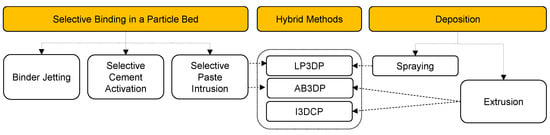
Figure 5.
Recent developments in hybrid concrete additive manufacturing methods (own graphic).
In A3DCP, cement-based filaments are deposited on a coarser aggregate in the particle bed according to the principles of extrusion [82]. Another special form in which the basic principles of SPI and SC3DP are combined is the LP3DP process developed at the Technical University of Braunschweig [83]. The particle bed contains a much coarser aggregate (up to 36 mm), into which the cement paste is applied in the SC3DP process.
Injection 3D concrete printing (I3DCP), also developed at the Technical University of Braunschweig, involves a liquid material being injected into a supporting medium using an extrusion process [84]. Basically, three variations are distinguished: concrete on suspension (CiS), suspension on concrete (SiC), or concrete on concrete (CiC) [84]. The structure build-up is not limited to vertical structure build-up by horizontal layering but can be, for the most part, free (restrictions in the nozzle guidance or in the chamber have to be considered). Due to the formative nature of the carrier medium, the definitional boundaries between additive and formative manufacturing processes are no longer clear for I3DCP (especially for SiC and CiC).
2.3. Comparison and Assessment
The characteristics of the processes described above are summarised in the following Table 1. Due to the process-related characteristics, a quantitative comparison of the different additive manufacturing processes is extremely difficult. The processes are subject to continuous further development, so the limits of the previous process technology have (probably) not yet been reached. The presentation of qualitative differentiating characteristics can, therefore, only be a cautious assessment. A presentation of qualitative differentiating characteristics seems to be more appropriate. The process-specific advantages and disadvantages are compared with each other in the following.

Table 1.
Overview of qualitative and quantitative characteristics of concrete additive manufacturing production methods.
Due to the use of very fine aggregates, particle-bed-based methods can produce filigree structures with high resolution. This is achieved without the characteristic stair-step effect. Due to the bedding of the dry-packed particles, there are few manufacturing constraints so that overhanging or bridging structures can be easily produced without additional support structures. The manufacturing time is also independent of the geometric complexity of the structure, at least as long as the unbound material can be removed relatively quickly and without leaving any residue. However, closed cavities cannot be fabricated. This is because the unwanted material cannot be removed without leaving residue.
Due to the chamber nature of the particle-bed process, the size of the component will always be coupled to the available printer dimensions. In terms of applications in the construction industry, particle-bed-based processes are, therefore, most likely to be suitable for the production of (small and large scale) precast concrete components.
One way to think is that one advantage of extrusion and spraying is that the material is deposited “freely” without a particle bed. However, this means that it’s really just a 2.5D rather than a 3D printing process. Separate support structures must first be integrated into the printing process as temporary or lost formwork for overhanging or bridging structures (e.g., window lintels).
However, when compared to particle-bed-based processes, free-form components can be fabricated much more quickly. Both the extrusion process and the spraying process are characterised by their high production/ printing speeds. Compared to the extrusion process, the spraying process achieves a high degree of interlocking and bonding of the layers due to the kinetic energy and compaction of the material. Moreover, robotic systems with different degrees of freedom are available for extrusion processes so that the component size and the process flexibility in terms of application location are much greater.
Since the selected AM method will have an impact on the structural design of the objects, this choice also affects the structural parameters. However, the strength properties of different AM methods were not part of the investigation, as this would require a more in-depth look at the individual compounds of the printing mixtures.
3. Methodology
As the comparison and assessment of the three main methods for additive manufacturing with concrete revealed, each process has its own specific advantages. Choosing the most suitable one, therefore, depends on the specific application. To investigate specific applications, different fabrication strategies for concrete structural components subjected to compressive and bending stresses are examined below.
This paper examines how concrete additive manufacturing can be used to fabricate concrete components subjected to compression (so-called “vertical components”) and bending (so-called “horizontal components”) based on a component-by-component approach. For this purpose, first of all, the basic functions and properties of structural components will be briefly presented. Then, for each group of components, selected examples are presented in order to identify the possibilities and to show fabrication strategies for different concrete additive manufacturing methods (see Figure 6). The following examples shown to describe the fabrication strategies can only give an insight. They are primarily intended to show the variety of the application of additive manufacturing.
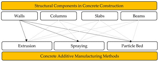
Figure 6.
Methodology for investigating fabrication strategies for different structural components in construction using CoAM (own graphic).
4. Fabrication Strategies for Additively Manufactured Concrete Components
(Reinforced) concrete structures in building construction (residential and non-residential) are mainly characterized by six groups of components: foundations, walls, columns, beams (girders), slabs, and additionally stairs or balconys (see Figure 7). For each group, the traditional cast-in-place manufacturing process can now be replaced by sophisticated precast or semi-precast solutions. In residential construction, a hybrid production strategy is often used. This means that mainly compression-stressed components (e.g., walls and columns) are produced on-site, while components subject to bending stresses (especially slabs and stairs) are prefabricated, delivered, and assembled as (semi) precast elements. Components subject to tension only (e.g., cables or tension rods) are generally only used in building construction to span large halls, which are not considered here.
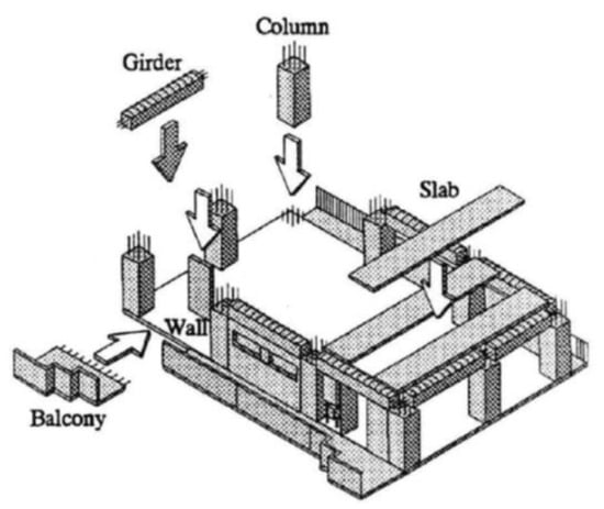
Figure 7.
Structural components in building construction. Reprinted with permission from [86].
As a consequence of bending, both compression and tension forces occur within a structural component. Concrete has high compressive strength but very low tensile strength (approximately 1/10th of compressive strength). Therefore, in the dimensioning of components that are subjected to bending loads, the role of the concrete is neglected, and the component is reinforced with steel at the points where tensile forces occur. Columns and walls can also be subjected to bending; however, for the purposes of further discussion, it will be assumed, under a simplified assumption, that columns and walls are mainly subjected to compression.
As the integration of reinforcement is currently one of the greatest process engineering challenges in additive manufacturing and is an area of intense research, only a few examples are given below, and references are provided for further reading.
4.1. Predominantly Compression-Stressed Components
Columns and walls are one of the types of structural components that are mainly subjected to compressive loads. Compared to similar types of construction (masonry, timber, or steel), these (vertical) concrete components can be subjected to very high compressive forces, with or without reinforcement [87]. In the following, both types of components will be examined.
4.1.1. Walls
Walls made of (reinforced) concrete play a central role in building construction. They are generally used where, in addition to enclosing space, high load-bearing capacity, impermeability, sound insulation, fire protection, or stiffening of buildings is required. This can be the case for basement walls, external walls, or the (stiffening) core of a high-rise building. Due to its material properties, concrete walls can carry high compressive loads but are inefficient thermal insulators, so the static and physical function (in this case, heat/cold protection) is usually provided by a thermal insulation composite system as an additional functional layer. From an architectural perspective, reinforced concrete walls with smooth or textured surfaces can be designed as “exposed concrete” and thus also have a design function.
To date, reinforced concrete walls have mostly been produced as volumetrically filled components with regular cross-sections and surfaces. They are mainly manufactured using standardised formwork. The basic principle of additive manufacturing processes is to produce components in comparatively thin layers. This opens up the possibility to design components in a completely new way and to integrate additional functions, e.g., structural-physical properties, in a structurally optimised way.
An investigation of 3D printing structures in general (including site and fabricator) and extrusion-based wall components, in particular, was carried out by [39,88]. According to [88], walls represent the most common use case so far. Walls produced using the particle-bed process have not yet been realised and will not be discussed further in the following.
- Extrusion-based fabrication strategies:
The majority of printed (hollow) walls to date have been fabricated in situ [88]. For example, in Germany’s first 3D-printed house in Beckum, wall components (with reduced loads) were fabricated as hollow walls, each consisting of two 60 mm wide filament strands [89]. Being able to fabricate in thin filaments results in the release being only able to produce solid wall structures. Thereby, it is possible, on the one hand, to insert a loose material as thermal insulation in the hollow and, on the other hand, in the case of higher static stress, to fill the hollow walls (as lost formwork) with concrete on site [39,89]. During the printing process, openings for plumbing or electrical installations can be manually cut out [88]. Thin reinforced stirrups are mostly manually inserted during the printing process to ensure the stability of the component in the fresh state. Until now, the integration of openings (windows or doors) has usually been carried out using a type of lintel formwork (formwork of the open area with wooden planks and steel pipe supports) and requires manual activities and sometimes interrupts the printing process. Ref. [90] are carrying out research into automated lifting of precast lintels.
Another example of extrusion-based concrete walls can be found in a 640 m², two-storey office building in Dubai by Russian company Apis Cor. Those walls were stiffened with “zigzag” “intermediate filaments [91]. After the printing process, vertical reinforcing bars were manually inserted at predefined positions and then cast in place [39].
From a design point of view, the layering principle means that conventional fair-faced (exposed) concrete qualities can only be achieved to a limited extent due to the stair-step effect, but also that new types of fair-faced concrete can be realised through a targeted arrangement of the layer patterns (textures, decorations). A combination of form and function is possible by locally increasing or decreasing the cross-sections, depending on the structural requirements. For example, the Seoul-based design studio SWNA used the principles of concrete 3D printing to create five concrete walls for the Gwangju Design Centre, with a design that imitates curtains fluttering in the wind [92].
The sound insulation properties of concrete walls (absorption) can be selectively improved by the shape of the outer texture [93]. Finer filament widths (<50 mm) can be used, for example, to create honeycomb or internal cellular structures. These contribute not only to stiffening but also to improving the thermal insulation properties [94,95,96]. In addition to the type of cell structure (open or closed form, honeycomb or rectangular cells, and the size of the cells), the material behaviour has a significant influence, so that, e.g., lightweight concretes can be used or additives such as glass fibres or polymers can be mixed in. By combining building physics and structural requirements, multifunctional walls can be created. The functional zones are separate but can be manufactured in a continuous (integrated) printing process. In addition, the wall components no longer have to follow a continuous cross-section. Instead, they can follow adapted cross sections, e.g., in corners, in order to avoid thermal bridges and prevent mould formation while considering the required load-bearing capacity (improvement of resource efficiency) [96].
So far, walls are usually designed either without reinforcement as a pure compression-loaded element (as a cavity wall or solid wall) [39] or manually reinforced and cast-in-place (3D-printed geometry as permanent formwork [88]). However, since walls are not only used for vertical load bearing but also for structural stiffening (wall plates for lateral load bearing, e.g., due to wind or earthquake), practical reinforcement strategies are essential. Approaches to reinforcement integration are extremely diverse, ranging from the use of a wide variety of short fibres to the use of penetration reinforcement (insertion of steel nails or short reinforcing bars) to the pre-welding of reinforcing bars.
In the reinforcement strategies that are currently being pursued, the timing of the installation of the reinforcement (before, during, or after the printing process) plays a very important role [97]. Reinforcement integration as an automated process step could bring 3D concrete printing closer to widespread practical implementation in construction. Various overviews of current reinforcement strategies are given in [23,24,76,97,98]. In the meantime, in the absence of practical reinforcement solutions, mostly conventional, unreinforced components are fabricated. In particular, extrusion printing is often used to replace masonry walls [39]. Preliminary studies indicate that extrusion printing can be more efficient in terms of labour productivity than conventional masonry construction [99].
The extrusion process has mainly been used “in situ”, but there are additional possibilities for the production of semi-finished products (so-called double-walled elements or element walls) on-site or off-site. In conventional precast construction, two thin precast slabs (4–7 cm thick) are joined in the factory by lattice girders to form an element wall with a (hollow) gap. The gap is filled with in-situ concrete after transport to the construction site. Similar considerations apply to 3D printed walls, mainly due to the hollow space created by the outer filament strands (see Figure 8).
For walls and ring beams, the company Nidus3D has successfully used a gantry printer to print single components on-site and then lift them into place (on-site AMC) for the construction of a two-storey residential building [100]. In this way, components can be prefabricated on-site, and transportation and assembly constraints can be overcome.

Figure 8.
Examples of different fabrication strategies for walls: (a) hollow wall with post-installed insulation [101], with permission from Peri 3D Construction, (b) design walls with external wavy structure [92], with permission from Hayeon Yoo, SWNA; (c) walls as prefabricated elements manufactured on-site [100], copyright © Nidus3D 2023. (d) wall with internal cellular structure (here: honeycomb) [95], with permission from Fabian Jaugstetter.

As shown above, extruded walls generally consist of one, two, or more filaments that form the external contours (and internal structures) of the wall, creating a hollow if necessary [88]. Thereby, extruded walls can be distinguished by the following:
- The type of internal structure (e.g., stiffened grid or equivalent pattern)
- The type of use (indirectly used as lost formwork with or without in-situ reinforced concrete or as a directly used structural component)
- The type of load bearing (reinforced or unreinforced)
- The functional integration (e.g., insulating or electrical cabling)
- The surface finish (ornamentation or quality of the exposed concrete)
In Figure 9, the aforementioned fabrication strategies for concrete walls using the extrusion method are visualized schematically.
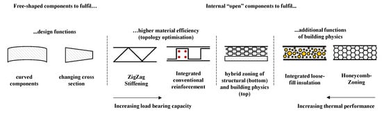
Figure 9.
Fabrication strategies of concrete walls using extrusion (own graphic).
- Spraying-based fabrication strategies:
Due to the larger filament width and the overall lower printing resolution (see previous chapter), spray-based processes are mainly suitable for the production of solid wall structures of varying geometric complexity. The focus is not on structural optimisation, but on a shape adapted to the load (material efficiency) with optimised force flow (reinforcement guidance) [11]. So far, different fabrication strategies for the production of freeform and reinforced wall components have been tested at the TU Braunschweig. For the fabrication of a double-curved reinforced concrete wall, first of all, a wave-shaped component structure was produced in sections, and the horizontal reinforcement was inserted. After completion of the wall core, vertical reinforcement bars were inserted into the valleys of the wall, and then the wall surface, including a concrete cover, was completed in a second printing process (second layer printing) [73]. In principle, it is also possible to prefabricate the reinforcement and then spray the concrete layer by layer (reinforcement supports concrete) (see as well comments on columns) [76]. Current research at the DBFL includes parallel robot-assisted reinforcement integration and the production of fair-faced concrete surfaces by subtractive finishing processes.
So far, the SC3DP process has only been used for the production of prefabricated components. Therefore, future research will need to be carried out to test SC3DP on-site. Further solutions are also needed, as walls are rarely produced without openings (windows, doors, penetrations). Due to the kinetic energy of the material application, SC3DP can (theoretically) also be used to apply cantilevers at perpendicular angles to the wall, which conventionally would normally require an increased effort in formwork [68] (see Figure 10).
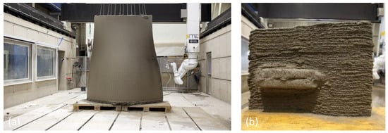
Figure 10.
Fabrication of a double curved wall (a) [73], Reprinted with permission from [73] and © ITE, TU Braunschweig; and a rectangular printed cantilever (b), reprinted with permission from [68] and H. Lindemann.
4.1.2. Columns
In addition to walls, columns are the second most common structural component that have been fabricated using concrete additive manufacturing [88]. Columns are one of the main parts of a reinforced concrete skeleton structure, which is essentially based on the systematic gridded arrangement of columns. Vertical loads are first distributed to the columns via the floor slabs (floor slabs) and then to the foundation. Columns are primarily used to transfer vertical loads and only rarely perform other functions (such as incorporating electrical or plumbing ducts). Circular columns can be constructed relatively easily and to a high quality in situ using what is known as column formers, while steel frame formwork (similar to that used for walls) is often used for rectangular columns. If a column is subjected to excessive point loads, there is a risk of so-called punching shear failure due to high shear forces. Theoretically, the geometry of the column head could be adapted to the slabs in a formwork-optimised way (e.g., mushroom slabs). However, this is rarely carried out due to formwork costs, space requirements, or architectural requirements. To increase the capacity of slender columns, shear reinforcement is usually provided in the area of the column head.
- Extrusion-based fabrication strategies:
Extruded columns differ only slightly from extruded walls. Columns are mainly used for vertical load transfer. Therefore, they are usually designed in standardised shapes (rectangular or round) or very slender with high-strength concrete. In the case of additively manufactured columns, the focus is on topology-optimisation and material-efficient load transfer [102]. This applies, in particular, to the upper part of a column in the area of the slab connection (column head). In principle, “resolved” internal structures, as in the case of walls, are possible [102], but from a static and design point of view—provided there are no space problems—a resolved complex external structure is also feasible [103].
For most columns, as with walls, a (lost) or permanent formwork is first printed, which is then manually reinforced and casted in place [104]. However, the method of reinforcing these columns differs: in addition to conventional reinforcement, post-tensioning is sometimes applied [102]. In a similar way, the extrusion process can be used, for example, to produce alternative surface textures as a new type of fair-faced concrete or to optimise the shape of the structure [105,106]. Examples are given below in Figure 11.
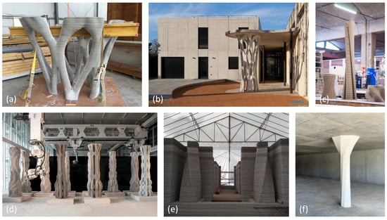
Figure 11.
Examples for the fabrication of columns by extrusion: from left to right: (a,b) prefabricated columns optimised for force flow (subsequently cast conventionally), Reprinted with permission from [103], (c–e) individualised and freeform architectural columns, (c) prefabricated “design” columns [105], with permission from Volker Ruitinga, Veritico; (d) prefabricated “design” columns with post-tensioning [107], with permission from Ana Anton, DBT, ETH Zürich: Concrete Choreography Project, MAS D-Fab 2018–2019: Columns inside The Robotic Fabrication Lab at ETH Zurich. Photo: Axel Crettenand, Digital Building Technologies; (e) in-situ printed columns [108], with permission from Andrey Rudenko, Total Kostums; (f) column modified to meet the applied load, © Affentranger Bau AG (The column shown is only intended to illustrate a conceivable adaptation of the upper area. No information is available whether the column has been optimised in terms of shape) [109].
- Spraying-based fabrication strategies:
The material application in the SC3DP process is too rough for the production of the previously described patterns, so the focus here is on optimising the load distribution of the vertical loads resulting from the slabs. Analogous to the walls produced by the SC3DP method, there are two approaches suitable for reinforced columns [11,110]:
- (1)
- concrete supports reinforcement
- (2)
- reinforcement supporting concrete
The full potential of SC3DP has not yet been realised, as the columns produced to date are very similar to conventional columns (see Figure 12). Shape-optimised column heads, however, could prevent the risk of the aforementioned punching shear failure. The first approaches to shape-optimised columns are presented in [111] (see Figure 13).
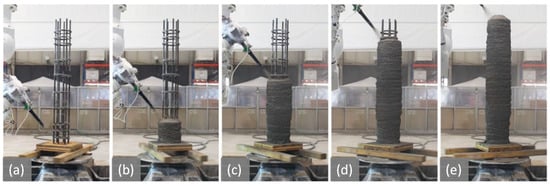
Figure 12.
Production of columns by the spraying method—Part 1: Production using a rotating turntable according to the principle “reinforcement supporting concrete” in five steps from (a–e) [11], Reprinted with permission from ITE, TU Braunschweig.
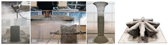
Figure 13.
Examples of the production of columns by spraying method—Part 2: Fabrication of hollow columns with an adapted cross-section (on the left): Steps: (a) Printing of hollow concrete columns using the SC3DP technology, (b) CNC cutting of the joint geometry, (c) pre-stressed concrete column, dry joined from four segments [11], Reprinted with permission from ITE, TU Braunschweig. On the right: production of a column head (on the right) [111], Reprinted with permission from Lukas Lachmeyer, Match, LU Hannover.
As shown, columns are conventionally very efficient, predominantly compression-loaded structural components that mainly fulfil a static function. The fabrication strategies presented so far illustrate (1) the possibility of combining the aesthetic and structural design of columns on the one hand and (2) the fabrication of forms that are suitable for the flow of forces on the other. Traditionally, this is often only possible with additional effort and cost, so, in most cases, “conventional” columns are only produced with standard cross-sections.
4.2. Predominantly Bending-Stressed Components
Slabs (floors), beams, and T-beams are typically subjected to bending stress. As a result of bending, compressive and tensile forces occur within a component. The layering principle of additive manufacturing leads, as a first consequence, to the production of components that are primarily subjected to compressive stress and not to bending stress (vertical material application in the direction of loading). For this reason, selected approaches, strategies, and prototypes are presented in more detail below than for columns and walls.
4.2.1. Slabs
Like walls, slabs fulfil a number of functions: They are load-bearing, enclose space, and provide sound and thermal insulation. Reinforced concrete slabs allow large spans and are typically 20 to 30 cm thick. As a result, they account for a large proportion of the mass of a building. In order to save weight, reinforced concrete slabs can also be made with hollow elements. For this purpose, hollow plastic elements (e.g., Cobiax elements [112]) are placed between the upper and lower reinforcement bars in in-situ concrete construction. Alternatively, to utilise the thermal mass of the concrete, pipes filled with heating or cooling water can be installed to regulate the building and room temperature (so-called concrete core activation).
In the pilot projects that have so far been carried out with additive manufacturing of the vertical, compression-stressed components, the floor slabs have mostly been produced in a conventional way or by means of semi-finished products [39]. Due to the layering principle of additive manufacturing, the structural design of horizontal, predominantly bending-stressed components is much more difficult than vertical, predominantly compression-stressed load-bearing structures. Particle-bed-based processes have the advantage over freely applying AM methods (extrusion and spraying) in that they can always be manufactured with a supporting structure in place. This does not ideally apply to extrusion and spraying-based methods, so alternative solutions have to be found. Selected examples are presented below.
- Particle-bed-based fabrication strategies:
As part of the DFAB House (Digital Fabrication) research building project, a so-called “Smart Slab” was fabricated [113,114] (see Figure 14). The geometry of the Smart Slab is structurally optimised. It consists of a hierarchical grid of curved ribs with a depth of 30 to 60 cm. For the production, the slab was disassembled during the design process into several parts, prefabricated, and assembled on-site. The fabrication involved a combination of techniques: The formwork elements were first manufactured, assembled, and reinforced using the binder jet method. Then the slab elements were formed using customised plywood formwork elements (in a laser-based cutting process) to provide flat surfaces for the connection areas. Once transported to the site, the elements were connected with external tension bars. Compared to a solid concrete slab, approximately 70% of the weight was saved while maintaining the same load-bearing capacity.
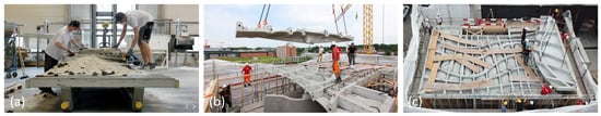
Figure 14.
Prefabrication of segmented slab elements using binder jetting: The SMART SLAB [115], copyright (a,b) Tom Mundy, DBT, ETH Zürich [114,116] (c) Andrei Jipa, DBT, ETH Zürich [117].
One of the first prototypes of a topology- and shape-optimised flooring element measuring 2.5 m × 1.0 m was presented by researchers at ETH Zurich [115] (see Figure 15). Using the binder-jetting method, a permanent formwork was first produced from a polymer-sand composite, which was freed from loose, unbound material and filled with ultra-high strength fibre-reinforced concrete (UHPFRC). The porous surface was then sealed with epoxy resin. The infiltration of the epoxy resin also improved the strength properties so that in empirical tests, the ceiling component withstood distributed area loads of 2.5 kN/m². With a ceiling height of only 25 cm, the component has the same dimensions as a conventional ceiling. However, material savings of up to 70 per cent have been achieved.
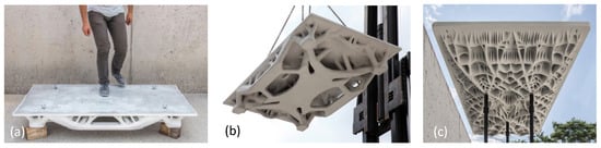
Figure 15.
Prefabrication of floor elements using the binder jetting method: Topology optimised concrete slab in 3D printed permanent formwork [118], copyright (a) Hyunchul Kwon, DBT, ETH Zürich [117], (b,c) Andrei Jipa, DBT, ETH Zürich [119].
- Extrusion-based fabrication strategies:
Researchers at ETH Zurich offer another interesting approach with the so-called foam 3D printing. They demonstrated their approach using a 2.0 m × 1.3 m ribbed slab element as an example [120,121] (see Figure 16). The fabrication strategy was to first erect the formwork for the slab conventionally (including slab and edge formwork) and fill it with foamed concrete recess elements of different sizes. The foamed concrete elements were prefabricated using a robotic arm and manually placed on the slab formwork as lost or temporary formwork elements. The actual topology-optimised slab geometry was produced in a subsequent step by pouring ultra-high-strength fibre-reinforced concrete.
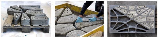
Figure 16.
Prefabrication of slab elements in the Foam 3D printing process by subsequently removing 3D printed recess elements [122], with permission from Patrick Bedarf, DBT, Zürich [123].
This idea has already been used by researchers at Graz University of Technology to produce an 8 m × 3 m topology optimised slab, but using cement-based hollow core formwork elements [124] (see Figure 17). The hollow elements were produced in 22 layers (9 mm × 18 mm each) using an extrusion process with a C85 mortar and fixed upside down on a mould table with silicone sealant. For the fabrication of the floor slab, prefabricated reinforcement cages were then lifted along the paths of the stress trajectories and placed into the formwork gaps. Once the edge formwork was in place, the concrete slab was poured using C30/37 concrete. According to the authors, material savings of approximately 35% were achieved for the same load-bearing capacity and the same amount of deflection.
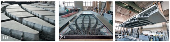
Figure 17.
Prefabrication of a slab using extrusion and conventional casting [124], with permission from (a,b) G. Hansemann, (c) R. Schmid, ITE, TU Graz.
- Spraying-based fabrication strategies:
An alternative approach is offered by the SC3DP process. Researchers at the Technical University of Braunschweig have succeeded in using the SC3DP process to print ribs with a variable cross-section onto a 6 cm thick precast reinforced concrete slab [11] (see Figure 18). The ceiling is similar to a PI beam, combining the load-bearing properties of a slab and a beam. Alternatively, another demonstrator was produced in which the ribs for a point-supported slab were added in an optimised form—also with a variable cross-section [11].
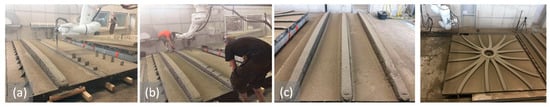
Figure 18.
Prefabrication of hybrid slab components using spraying and conventional prefabricated slab elements (“Add-On 3D-Printing”): (a) Printing of the ribs, (b) insertion of the reinforcement, (c) beam element after printing on the reinforcement [11], with permission from ITE, TU Braunschweig. The image on the right shows a 16 m² point supported ceiling [11], Reprinted with permission of ITE, TU Braunschweig.
What is more, a British research group used a spray process to produce nine double-curved ribbed shell elements of glass fibre reinforced concrete [125]. These were then assembled to form a 4.5 m × 4.5 m wide shell structure. Following a design based on principal stress line analysis, the overall structure was segmented into three different shapes. An adaptive formwork system (pin-bed mould), which provides a flexible formwork surface and specifies formwork elements sizes, serves as the basis for the injection process. This process, known as automated robotic concrete spraying (ARCS), provides another approach to implementing the form-follows-function design approach. The examples described above show that slabs fabricated using the spraying method are mostly used in an off-site and hybrid-fashion, combining traditional or modern formwork solutions with additive manufacturing.
To sum up, the following different fabrication strategies for slabs are currently used:
- “Direct” prefabrication of topology-optimised slabs as small components (Particle Bed).
- “Indirect” prefabrication of topology-optimised slabs using 3D printed hollow elements to place as recesses. It was shown that extrusion was only used indirectly instead of printing a “slab” directly (Extrusion).
- Prefabrication of (structural optimised) slabs as “add-on” printing using already prefabricated semi-finished slabs or modern formwork solution as a counterpart (Spraying).
4.2.2. Beams
Beams are the bending counterpart to columns. Beams are usually rectangular or have an optimised shape as T or H beams, whereas columns can be designed as round columns for aesthetic reasons. Beams are used to bear vertical area or line loads and distribute them to vertical components. This is why these components are (intended to be) used to span several metres in some cases. However, beams are also affected by the “problem” of necessary support structures in the printing process.
For this reason, alternative concepts need to be developed (corresponding Figure 19). For better understanding, the fabrication strategies for beams are described before showing fields of application:
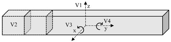
Figure 19.
Schematic Visualisation of possible fabrication strategies incl. printing and assembly (own graphic).
- V1: The beam is printed along the longitudinal axis (0°—no rotation)
- V2: The beam is produced segmented and then joined by external post-tensioning. (90° individual segments rotated around the x-axis).
- V3: The beam is not segmented and is printed as a “column” and conventionally reinforced with steel bars or subsequently post-tensioning. The “column” is then laid down as a “beam”.
- V4: The beam is flipped along the longitudinal axis and printed (component rotated 90° around the y-axis; placed sideways).
- Particle-bed-based fabrication strategies:
A commonly used approach to beam fabrication is to first divide the beam into several components for fabrication in the design process, fabricate them individually, and then post-tension (V2, see Figure 20). In the particle-bed processes, the beam does not necessarily need to be rotated due to the supporting effect of the particle bed but can be printed in its final position, as researchers at ETH Zurich have shown using binder jetting [126].
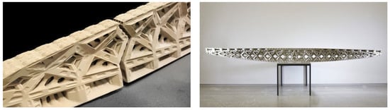
Figure 20.
Example of an assembled 3D printed beam according to variant V1 [126], with permission from Ana Anton, DBT, ETH Zürich.
- Extrusion-based fabrication strategies:
According to the first variant (V1), the extrusion process can be used theoretically to produce a permanent formwork due to the layer principle, which can also be manually supplemented with a reinforcement cage and concreted due to the H*B ratio of the beams. However, this does not fully exploit the potential of additive manufacturing.
The second option (V2) requires, firstly, a segmentation into individual components and, secondly, a 90-degree rotation around the x-axis (vertical positioning) before the vertical printing can begin. For the connection to the original component, the individual segments are positioned in their final position and connected to each other by means of internal or external post-tensioning. In this case, it is possible to integrate an opening along the y-axis of the beam for internal post-tensioning. In principle, it is also possible to print the beams first as columns (V3, rotated around the x-axis) and then rotate them into their final position (back) [127].
In the fourth possible variant (V4), the part is not segmented but simply rotated 90 degrees along its y-axis (laid sideways) so that the structure can be built “conventionally”. An example of this has been developed by Hyperion Robotics together with the Create Group at the University of Southern Denmark (SDU) as part of the research project 3DLightBeam—3D Printed Lightweight Beam [128] (see Figure 21). Among other things, lightweight concrete was applied along the main stress paths and in a grid-like structure.
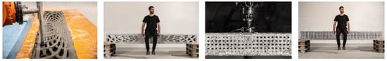
Figure 21.
Examples of variant 4 and extrusion printed beams with different paths planning [129], with permission from SDU Create—Prof. Roberto Naboni.
In a hybrid version of V2 and V4, the researchers involved in the WASP project first segmented a 3D-printed beam and then rotated it by 90 degrees around the y-axis (with the individual segments placed on their sides) [130]. Externally tensioned steel rods provide the load-bearing effect of the truss-like beam (see Figure 22).
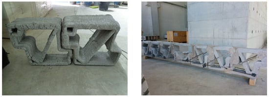
Figure 22.
Example of a beam prefabricated by extrusion. The beam was segmented for fabrication and was rotated by 90° to the y-axis (variant 2, left) and then connected by means of external reinforcement (right) [131], with permission from/Copyright © WASP.
- Spraying-based fabrication strategies:
The coarser material application also prevents the SC3DP process from producing fine support structures in the production of beams. In contrast to extrusion processes, spraying-based processes allow the application of three-dimensionally curved concrete paths and the positioning of tensile reinforcement in accordance with the flow of forces—without additional support reinforcement (currently still manually). In tests at the Technical University of Braunschweig, a textile-reinforced concrete beam with a length of 2.4 m, a height of 0.36 m, and a width of 0.18 m was produced [132] (see Figure 23). For this purpose, the printing process was interrupted for a short time, and a textile reinforcement made of carbon was integrated manually. After curing, the beam was machined using a subtractive unit. The printing orientation of the component was carried out against the background of the final load-bearing or assembly situation and, therefore, did not need to be erected or subsequently reinforced [132]. It is also conceivable to produce a beam by spraying according to the aforementioned “reinforcement-supported concrete” variant, as illustrated by the start-up company Aeditive on its website. In this case, a reinforcement cage is placed first, and then the concrete is sprayed around it [77].
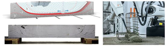
Figure 23.
Examples of beams produced by the spraying-based process: on the left: a beam with textile reinforcement along the tensile stress trajectories (concrete supports reinforcement) [132], with permission from Robin Dörrie, ITE, TU Braunschweig; on the right: Strategy to the fabrication of a beam with conventional reinforcement (reinforcement supports concrete) [77], with permission from Alexander Türk/Aeditive.
5. Discussion: Trends, Potential and Future Challenges
A variety of manufacturing strategies can be identified from a differentiated examination of the component groups predominant in structural engineering for the application of additive concrete manufacturing processes. While compressively stressed components are often produced in situ by extrusion, bending-stressed components are usually prefabricated with permanent (negative) formwork using particle-bed or hybrid-spray processes. Although additive manufacturing, by definition, allows for direct geometry and component design without the need for permanent shuttering, the extrusion process, in particular, allows for more complex shuttering shapes to be realised and to be cast in place (indirect application).
Whereas in the case of particle-bed processes, the component geometry is mostly limited by the size of the printer. In the case of extrusion, the “free” material application allows the production of larger components or whole component groups. Similarly to columns, research and prototyping of beams are focused on increasing material efficiency. Reduced material usage offers several benefits: reduced CO2 emissions, reduced component weight, and reduced transportation costs. Recesses in the beam created by topology optimisation can also be used for building services installations. This replaces the need for costly subsequent core drilling. The final chapter discusses the trends identified, the associated aims, and the remaining issues for each type of method.
5.1. Extrusion Based CoAM
Trends: The use of extrusion-based concrete additive manufacturing processes for the fabrication of structural components under compression is predominant. In many cases, the printed wall and column cross-sections are statically more similar to masonry than to reinforced concrete components. Although the direct geometry and structure of the component can be achieved by additive manufacturing without the need for formwork, additive manufacturing processes also make it possible to produce more complex formwork shapes and adapted cross-sections and to cast this “permanent” formwork with conventional fresh concrete. While structural components under compression are simply produced on-site, and structural components under tension (slabs and beams) are mainly prefabricated and transported to the construction site as semi-finished or finished products, this is not the case for prefabricated slabs.
Potential: The in-situ production of walls using the extrusion process promises not only lower construction costs due to the elimination of labour-intensive formwork but also the rapid construction of curved or cross-sectionally modified walls. In particular, the productivity of conventional reinforced concrete walls depends to a large extent on the design of the component/structure and the formwork planning that is adapted to it. 3D printing breaks this link and makes it possible to produce new or more complex component shapes (especially walls) with a consistently high level of productivity. Columns could mostly be produced indirectly. Therefore, the component could be designed according to the flow of forces and then printed as a lost formwork, which is reinforced and casted in place afterwards. For the on-site production of ceilings, consideration could be given to using the already existing robotic systems (for example, gantries) for the time of the slab production as a concrete pump.
Challenges: Printing in horizontal layers contradicts the principle of vertical (continuous) reinforcement bars (90° to the layer). Practical approaches to reinforcement integration and novel concepts for reinforcing are key challenges for the extrusion process. Attempts have been made, for example, to manually place the vertical reinforcement in advance and to print the material using a type of “lance” that is longer than the reinforcement already installed. However, this would require many long overlaps or expensive screw connections as well as additional cast-in-place concrete. However, this strategy can be seen as just an alternative way to print permanent formwork and does not exploit its full potential. In particular, and for the further in-situ application, the detailed design of support points and the integration of connection joints form slab to wall components need to be investigated. In the case of hollow wall structures and column cross-sections, it is necessary to prevent the material of an in-situ concrete slab from flowing into the cavities of the walls/columns.
5.2. Spraying-Based CoAM
Trends: The spraying process has so far only been used in university research, but the components produced so far illustrate the flexibility of the process. These include walls, columns, slabs, and beams. So far, all components have been produced “directly” rather than “indirectly” as permanent formwork. However, for slabs, traditional or modern formwork solutions have been used. The spray process appears to be particularly suitable for the individual prefabrication of geometrically complex shapes. This is also suggested by the fact that a start-up company, Aeditive, developed at the Technical University of Braunschweig, has devoted itself to this production strategy.
Potential: Due to the “stronger” material application in thicker and wider layers compared to the other two processes, non-standardised component shapes (especially for walls) can be realised with comparatively high productivity. For predominantly bending-stressed components such as slabs and beams, it is possible to produce elements and structures adapted to the flow of forces (see descriptions of beams or reinforcement guidance). Until now, prefabrication has been characterised by a high level of manual labour for complex or freeform concrete components. The automated production of individualised concrete components using the spraying process offers great potential for increasing the degree of automation and reducing labour costs. In combination with the subtractive 5-axis module of the DBFL, it is also possible to produce concrete components with a high-quality fair-faced concrete surface.
Challenges: In the production of walls using the extrusion process, it is relatively “easy” to produce recesses using “standard solutions” (e.g., wooden structures or beams). However, new solutions are required, especially for the production of walls using the spray process. Further research is also being carried out into the integration of reinforcement in spray processes.
5.3. Particle-Bed-Based CoAM
Trends: The application of particle-bed-based CoAM is concentrated on prefabricated components subject to bending stress. This is mainly due to the fact that manufacturing in the particle bed always has a supporting effect, and overhanging structures can be realised. However, walls and columns have hardly ever been produced using the particle-bed process.
Potential: The potential of particle-bed-based methods lies in the aforementioned supporting effect of the particle bed and the subsequent removal of unbound particles. This makes it possible to produce (internal, e.g., hexagonal) structures like no other process. As a result, structurally optimised floor elements can be prefabricated and transported to the site as (semi) finished parts: First and foremost, increasing material efficiency or reducing material use offers several benefits: reduced CO2 emissions, reduced component weight, and lower transport and assembly costs. Similar to columns, research and prototyping of particle-bed-based methods for prefabrication of slabs and beams are focused on increasing material efficiency so that the material is applied in accordance with the underlying structural load/beam models or stress distributions. For beams, recesses created by topology optimisation could also be used for building services installations, replacing subsequent costly core drilling. However, alternative approaches to reinforcement integration are also required.
Challenges: The need for appropriate reinforcement integration strategies is nowhere more evident than in bending-stressed components. Reinforcement integration is unavoidable in order to (economically) span large areas or to achieve ductile material behaviour. The integration of a horizontal (planar) reinforcement (longitudinal reinforcement in beams or surface reinforcement in slabs) still requires further research. In particle-bed-based methods, possible solutions could be to print the reinforcement, to use fibres, or to involve post-tensioning.
6. Conclusions
6.1. Summary
Concrete 3D printing is still a relatively new manufacturing process, despite a large number of scientific research activities and realised construction projects. The aim of this article was to present the basic characteristics and principles of additive manufacturing with concrete as well as to identify fabrication strategies for structural components.
For this purpose, additive manufacturing was firstly classified and then differentiated from the subtractive and formative processes. The three main groups (extrusion, spraying-based and particle-bed-based processes) were then examined and attempts were made to identify key distinguishing features. Due to the wide variety of materials, robot types, and process technologies used in research and practice, it was difficult to make a quantifiable distinction.
In the second part of this paper, compressive and bending-stressed components were used as examples to investigate which of the processes presented in the second section can be used to fabricate (reinforced) concrete components and which fabrication strategies underlie them. In the piloted and already realised components, the (mainly) compression-stressed components are often produced using the extrusion method. The transition between formwork and component production is sometimes fluid. While walls (with a dissolved wall structure) are produced as a direct component, concrete is subsequently poured at specific points to produce monolithic components (used as formwork), or supports are selectively integrated. Walls and columns (compressive components) are predominantly cast in situ. So far, slabs/ceilings and beams have been prefabricated. This may not be surprising, as the layering principle for these components always requires a flat surface to “print” on.
The research has shown that extrusion is the most appropriate choice for components subject to compressive stress, while for components subject to flexural stress, the particle-bed, and spraying-based processes offer a variety of manufacturing strategies.
The final evaluation shows that different additive manufacturing strategies (direct part vs. indirect mould; in situ, on-site, or off-site) are being used and will need to be integrated into the conventional design and construction process in the future. In the short term, it is likely that the application of 3D printing of concrete will be implemented primarily as a permanent formwork. For the long term, regulatory requirements and practical solutions for (partially) automated reinforcement integration need to be developed.
6.2. Outlook
It can be assumed that both conventional construction and additive manufacturing will be used in parallel in the context of a holistic view. Thus, a hybrid mixed construction method is likely to emerge in the future. The first indications of this can be seen in the fabrication strategies for slabs as well as in the examples of building projects that have been realised to date: Slabs in all 3D printed buildings have been produced conventionally (on-site or with semi-finished parts). Based on this assumption, and taking into account previously neglected interests (e.g., fire safety and existing building measures), the planning and execution processes of additive manufacturing processes must be integrated into existing structures of “conventional” construction. This is especially true when different building fabrications/productions strategies are to be combined: The fabrication of walls using in-situ additive manufacturing, the prefabrication of columns and slabs, and the production of beams on-site using robotic systems that have already been transported to the construction site. Thus, open research questions include the following:
- How will a “design for AM” approach effect the conventional design and construction process?
- How will the design process change if AM-specific structural-design requirements are integrated into the early design stages?
- What is the appropriate manufacturing process to use? (conventional or AM?)
- When does the selection of a construction method have to be made in the design process?
The potential advantages of in-situ hybrid manufacturing strategies can be justified with the combination of the strengths of both approaches. This means that the implementation of AM for compression-stressed elements (e.g., extruded walls) is in combination with conventional manufacturing processes for bending-stressed elements (e.g., ceilings).
Author Contributions
Conceptualization, G.P.; methodology, G.P.; investigation, G.P.; resources, P.S.; writing—original draft preparation, G.P.; writing—review and editing, G.P. and P.S.; visualization, G.P.; supervision, P.S.; project administration, P.S.; funding acquisition, P.S. and G.P. All authors have read and agreed to the published version of the manuscript.
Funding
The research presented in this paper is being conducted within the project “Integration of additive manufacturing in the construction process (C06)”. The project is part of the collaborative research centre “Additive Manufacturing in Construction—The Challenge of Large Scale,” funded by the Deutsche Forschungsgemeinschaft (DFG, German Research Foundation) project number 414265976—TRR 277.
Data Availability Statement
Data sharing not applicable. No new data were created or analyzed in this study. Data sharing is not applicable to this article.
Acknowledgments
We acknowledge the financial support by the Open Access Publication Funds of the Technische Universität Braunschweig.
Conflicts of Interest
The authors declare no conflict of interest.
References
- Lehne, J.; Preston, F. Making Concrete Change: Innovation in Low-carbon Cement and Concrete. 2018. Available online: https://www.chathamhouse.org/2018/06/making-concrete-change-innovation-low-carbon-cement-and-concrete (accessed on 18 April 2023).
- Statista. Cement Production Global 2022|Statista. Available online: https://www.statista.com/statistics/1087115/global-cement-production-volume/ (accessed on 22 March 2023).
- International Energy Agency; World Business Council for Sustainable Development’s (WBCSD) Cement Sustainability Initiative. Technology Roadmap: Low-Carbon Transition in the Cement Industry. 2018. Available online: https://www.wbcsd.org/contentwbc/download/4586/61682/1 (accessed on 18 April 2023).
- Bundesministerium für Umwelt, Naturschutz, Bau und Reaktorsicherheit (BMUB). Übereinkommen von Paris. Available online: https://www.bmuv.de/fileadmin/Daten_BMU/Download_PDF/Klimaschutz/paris_abkommen_bf.pdf (accessed on 18 April 2023).
- Hauptverband der Deutschen Bauindustrie. Produktivität im Bau(haupt-)gewerbe—Ein Statistischer Befund. Available online: https://www.bauindustrie.de/fileadmin/bauindustrie.de/Zahlen_Fakten/Auf_den_Punkt_gebracht/221102_Bi_auf_den_Punkt_gebracht_-_Produktivitaet_im_Bau_haupt_gewerbe_01.pdf (accessed on 22 March 2023).
- McKinsey Global Institute. Reinventing Construction: A Route to Higher Productivity. Available online: https://www.mckinsey.com/~/media/mckinsey/business%20functions/operations/our%20insights/reinventing%20construction%20through%20a%20productivity%20revolution/mgi-reinventing-construction-a-route-to-higher-productivity-full-report.pdf (accessed on 18 April 2023).
- García de Soto, B.; Agustí-Juan, I.; Hunhevicz, J.; Joss, S.; Graser, K.; Habert, G.; Adey, B.T. Productivity of digital fabrication in construction: Cost and time analysis of a robotically built wall. Autom. Constr. 2018, 92, 297–311. [Google Scholar] [CrossRef]
- De Schutter, G.; Lesage, K.; Mechtcherine, V.; Nerella, V.N.; Habert, G.; Agusti-Juan, I. Vision of 3D printing with concrete—Technical, economic and environmental potentials. Cem. Concr. Res. 2018, 112, 25–36. [Google Scholar] [CrossRef]
- Delgado Camacho, D.; Clayton, P.; O’Brien, W.J.; Seepersad, C.; Juenger, M.; Ferron, R.; Salamone, S. Applications of additive manufacturing in the construction industry—A forward-looking review. Autom. Constr. 2018, 89, 110–119. [Google Scholar] [CrossRef]
- Placzek, G.; Schwerdtner, P. Ableitung von Integrationsansätzen des “Beton-3D- Drucks“ in den Bauprozess anhand von Merkmalen der additiven Fertigung. Bauwirtschaft 2020, 5, 208–222. [Google Scholar]
- Kloft, H.; Hack, N.; Mainka, J.; Brohmann, L.; Herrmann, E.; Ledderose, L.; Lowke, D. Additive Fertigung im Bauwesen: Erste 3-D-gedruckte und bewehrte Betonbauteile im Shotcrete-3-D-Printing-Verfahren (SC3DP). Bautechnik 2019, 96, 929–938. [Google Scholar] [CrossRef]
- El-Sayegh, S.; Romdhane, L.; Manjikian, S. A critical review of 3D printing in construction: Benefits, challenges, and risks. Arch. Civ. Mech. Eng. 2020, 20, 4. [Google Scholar] [CrossRef]
- Baigarina, A.; Shehab, E.; Ali, M.H. Construction 3D printing: A critical review and future research directions. Prog. Addit. Manuf. 2023. [Google Scholar] [CrossRef]
- Strohle, M.; Sadique, M.; Dulaimi, A.; Kadhim, M.A. Prospect and barrier of 3D concrete: A systematic review. Innov. Infrastruct. Solut. 2023, 8, 21. [Google Scholar] [CrossRef]
- Kaszyńska, M.; Skibicki, S.; Hoffmann, M. 3D Concrete Printing for Sustainable Construction. Energies 2020, 13, 6351. [Google Scholar] [CrossRef]
- Al-Tamimi, A.K.; Alqamish, H.H.; Khaldoune, A.; Alhaidary, H.; Shirvanimoghaddam, K. Framework of 3D Concrete Printing Potential and Challenges. Buildings 2023, 13, 827. [Google Scholar] [CrossRef]
- Bhardwaj, A.; Jones, S.Z.; Kalantar, N.; Pei, Z.; Vickers, J.; Wangler, T.; Zavattieri, P.; Zou, N. Additive Manufacturing Processes for Infrastructure Construction: A Review. J. Manuf. Sci. Eng. 2019, 141, 091010. [Google Scholar] [CrossRef]
- Shakor, P.; Nejadi, S.; Paul, G.; Malek, S. Review of Emerging Additive Manufacturing Technologies in 3D Printing of Cementitious Materials in the Construction Industry. Front. Built Environ. 2019, 4, 2740. [Google Scholar] [CrossRef]
- Ma, G.; Wang, L. A critical review of preparation design and workability measurement of concrete material for largescale 3D printing. Front. Struct. Civ. Eng. 2018, 12, 382–400. [Google Scholar] [CrossRef]
- Paul, S.C.; van Zijl, G.P.; Tan, M.J.; Gibson, I. A review of 3D concrete printing systems and materials properties: Current status and future research prospects. RPJ 2018, 24, 784–798. [Google Scholar] [CrossRef]
- Puzatova, A.; Shakor, P.; Laghi, V.; Dmitrieva, M. Large-Scale 3D Printing for Construction Application by Means of Robotic Arm and Gantry 3D Printer: A Review. Buildings 2022, 12, 2023. [Google Scholar] [CrossRef]
- Chen, H.; Zhang, D.; Chen, P.; Li, N.; Perrot, A. A Review of the Extruder System Design for Large-Scale Extrusion-Based 3D Concrete Printing. Materials 2023, 16, 2661. [Google Scholar] [CrossRef]
- Cao, X.; Yu, S.; Cui, H.; Li, Z. 3D Printing Devices and Reinforcing Techniques for Extruded Cement-Based Materials: A Review. Buildings 2022, 12, 453. [Google Scholar] [CrossRef]
- Wu, Z.; Memari, A.; Duarte, J. State of the Art Review of Reinforcement Strategies and Technologies for 3D Printing of Concrete. Energies 2022, 15, 360. [Google Scholar] [CrossRef]
- Ahmed, G.H.; Askandar, N.H.; Jumaa, G.B. A review of largescale 3DCP: Material characteristics, mix design, printing process, and reinforcement strategies. Structures 2022, 43, 508–532. [Google Scholar] [CrossRef]
- Paolini, A.; Kollmannsberger, S.; Rank, E. Additive manufacturing in construction: A review on processes, applications, and digital planning methods. Addit. Manuf. 2019, 30, 100894. [Google Scholar] [CrossRef]
- Raphael, B.; Senthilnathan, S.; Patel, A.; Bhat, S. A review of concrete 3D printed structural members. Front. Built Environ. 2023, 8, 291. [Google Scholar] [CrossRef]
- Tay, Y.W.D.; Panda, B.; Paul, S.C.; Noor Mohamed, N.A.; Tan, M.J.; Leong, K.F. 3D printing trends in building and construction industry: A review. Virtual Phys. Prototyp. 2017, 12, 261–276. [Google Scholar] [CrossRef]
- Zhang, J.; Wang, J.; Dong, S.; Yu, X.; Han, B. A review of the current progress and application of 3D printed concrete. Compos. Part A Appl. Sci. Manuf. 2019, 125, 105533. [Google Scholar] [CrossRef]
- Hossain, M.A.; Zhumabekova, A.; Paul, S.C.; Kim, J.R. A Review of 3D Printing in Construction and its Impact on the Labor Market. Sustainability 2020, 12, 8492. [Google Scholar] [CrossRef]
- Peri. PERI Group Acquires Stake in COBOD International A/S. Available online: https://www.peri.com/en/company/press-releases/PERI-Group-acquires-stake-in-COBOD.html (accessed on 22 March 2023).
- Meisenzahl, M.; Dubai Is Now Home to the Largest 3D-Printed Building in the World. Insider [Online]; 30 December 2019. Available online: https://www.businessinsider.com/dubai-largest-3d-printed-building-apis-cor-photos-2019-12 (accessed on 25 April 2023).
- 3dprintedhouse. Project Milestone. Available online: https://www.3dprintedhouse.nl/en/project-info/project-milestone/ (accessed on 25 April 2023).
- COBOD. Kamp C|COBOD International. Available online: https://cobod.com/projects-partners/kamp-c/ (accessed on 25 April 2023).
- Brooke Bauguess. The Chicon House—ICON: The First Permitted 3D-Printed Home in the United States. Available online: https://www.iconbuild.com/projects/chicon-house (accessed on 25 April 2023).
- PERI 3D Construction GmbH. Germany’s First 3D-Printed Home. Available online: https://www.peri3dconstruction.com/en/beckum (accessed on 25 April 2023).
- PERI 3D Construction GmbH. Europe’s Largest 3D-Printed Apartment Building. Available online: https://www.peri3dconstruction.com/en/wallenhausen (accessed on 25 April 2023).
- Statistisches Bundesamt. Baufertigstellungen von Wohungen in Wohn- und Nichtwohngebäuden* in Deutschland in den Jahren 2022 bis 2021 (in Tausend) [Graph]. Available online: https://de.statista.com/statistik/daten/studie/39008/umfrage/baufertigstellungen-von-wohnungen-in-deutschland/ (accessed on 25 April 2023).
- Bos, F.P.; Menna, C.; Pradena, M.; Kreiger, E.; da Silva, W.L.; Rehman, A.U.; Weger, D.; Wolfs, R.; Zhang, Y.; Ferrara, L.; et al. The realities of additively manufactured concrete structures in practice. Cem. Concr. Res. 2022, 156, 106746. [Google Scholar] [CrossRef]
- Gebhardt, A. Generative Fertigungsverfahren: Additive Manufacturing und 3D Drucken für Prototyping-Tooling-Produktion, 4., neu bearb. und erw. Aufl. In Hanser; Ciando: München, Germany, 2013; ISBN 9783446436527. [Google Scholar]
- DIN Deutsches Institut für Normung e., V. DIN 8580:2022-12, Fertigungsverfahren—Begriffe, Einteilung; Beuth Verlag GmbH: Berlin, Germany, 2022. [Google Scholar]
- Buswell, R.A.; Bos, F.P.; Silva, W.R.L.d.; Hack, N.; Kloft, H.; Lowke, D.; Freund, N.; Fromm, A.; Dini, E.; Wangler, T.; et al. Digital Fabrication with Cement—Based Materials: Process Classification and Case Studies. In Digital Fabrication with Cement-Based Materials; Springer: Cham, Switzerland, 2022; pp. 11–48. [Google Scholar]
- Buswell, R.A.; da Silva, W.L.; Bos, F.P.; Schipper, H.R.; Lowke, D.; Hack, N.; Kloft, H.; Mechtcherine, V.; Wangler, T.; Roussel, N. A process classification framework for defining and describing Digital Fabrication with Concrete. Cem. Concr. Res. 2020, 134, 106068. [Google Scholar] [CrossRef]
- DIN Deutsches Institut für Normung e., V. DIN EN ISO/ASTM 52900:2022-03, Additive Fertigung-Grundlagen-Terminologie: Deutsche Fassung EN_ISO/ASTM 52900:2021; Beuth Verlag GmbH: Berlin, Germany, 2022. [Google Scholar]
- Lowke, D.; Dini, E.; Perrot, A.; Weger, D.; Gehlen, C.; Dillenburger, B. Particle-bed 3D printing in concrete construction—Possibilities and challenges. Cem. Concr. Res. 2018, 112, 50–65. [Google Scholar] [CrossRef]
- Volpe, S.; Sangiorgio, V.; Fiorito, F.; Varum, H. Overview of 3D construction printing and future perspectives: A review of technology, companies and research progression. Archit. Sci. Rev. 2022, 1–22. [Google Scholar] [CrossRef]
- Lim, S.; Buswell, R.; Le, T.; Wackrow, R.; Austin, S.; Gibb, A.; Thorpe, T. Development of a Viable Concrete Printing Process. In Proceedings of the 28th ISARC, 28th International Symposium on Automation and Robotics in Construction, Seoul, Republic of Korea, 29 June–2 July 2011; Kwon, S., Ed.; [Google Scholar]
- Khoshnevis, B.; Dutton, R. Innovative Rapid Prototyping Process Makes Large Sized, Smooth Surfaced Complex Shapes in a Wide Variety of Materials. Mater. Technol. 1998, 13, 53–56. [Google Scholar] [CrossRef]
- Khoshnevis, B. Automated construction by contour crafting—Related robotics and information technologies. Autom. Constr. 2004, 13, 5–19. [Google Scholar] [CrossRef]
- Mechtcherine, V.; Nerella, V.N. Beton-3D-Druck durch selektive Ablage. Beton-Stahlbetonbau 2019, 114, 24–32. [Google Scholar] [CrossRef]
- Lim, S.; Buswell, R.A.; Le, T.T.; Austin, S.A.; Gibb, A.; Thorpe, T. Developments in construction-scale additive manufacturing processes. Autom. Constr. 2012, 21, 262–268. [Google Scholar] [CrossRef]
- Otto, J.; Krause, M. CONPrint3D®: 3D-Druck als Innovation im Betonbau. In Festschrift zum 60. Geburtstag von Univ.-Prof. Dr.-Ing. Christoph Motzko; Fenner, J., Ed.; Institut für Baubetrieb der Technischen Universität Darmstadt: Darmstadt, Germany, 2017; pp. 571–586. ISBN 978-3-941925-29-8. [Google Scholar]
- Le, T.T.; Austin, S.A.; Lim, S.; Buswell, R.A.; Gibb, A.G.F.; Thorpe, T. Mix design and fresh properties for high-performance printing concrete. Mater. Struct. 2012, 45, 1221–1232. [Google Scholar] [CrossRef]
- Buswell, R.A.; Leal de Silva, W.R.; Jones, S.Z.; Dirrenberger, J. 3D printing using concrete extrusion: A roadmap for research. Cem. Concr. Res. 2018, 112, 37–49. [Google Scholar] [CrossRef]
- Alfani, R. Rheological test methods for the characterization of extrudable cement-based materials—A review. Mater. Struct. 2005, 38, 239–247. [Google Scholar] [CrossRef]
- Marchment, T.; Sanjayan, J.; Xia, M. Method of enhancing interlayer bond strength in construction scale 3D printing with mortar by effective bond area amplification. Mater. Des. 2019, 169, 107684. [Google Scholar] [CrossRef]
- Van der Putten, J.; Volder, M.d.; van den Heede, P.; Deprez, M.; Cnudde, V.; Schutter, G.d.; van Tittelboom, K. Transport properties of 3D printed cementitious materials with prolonged time gap between successive layers. Cem. Concr. Res. 2022, 155, 106777. [Google Scholar] [CrossRef]
- Placzek, G.; Schwerdtner, P. Vorüberlegungen bei der Anwendung robotischer Systeme—Eine baubetriebliche Untersuchung für den Beton-3D-Druck/A preliminary study of the impact of robotic systems on concrete 3D printing in the construction industry. Bauingenieur 2022, 97, 423–433. [Google Scholar] [CrossRef]
- Dörfler, K.; Hack, N.; Sandy, T.; Giftthaler, M.; Lussi, M.; Walzer, A.N.; Buchli, J.; Gramazio, F.; Kohler, M. Mobile robotic fabrication beyond factory conditions: Case study Mesh Mould wall of the DFAB HOUSE. Constr. Robot. 2019, 3, 53–67. [Google Scholar] [CrossRef]
- Labonnote, N.; Rønnquist, A.; Manum, B.; Rüther, P. Additive construction: State-of-the-art, challenges and opportunities. Autom. Constr. 2016, 72, 347–366. [Google Scholar] [CrossRef]
- Apis Cor. Project “Frank” by Apis Cor. Available online: https://www.youtube.com/watch?v=NX2AQCLNXbU (accessed on 3 November 2021).
- Gosselin, C.; Duballet, R.; Roux, P.; Gaudillière, N.; Dirrenberger, J.; Morel, P. Large-scale 3D printing of ultra-high performance concrete—A new processing route for architects and builders. Mater. Des. 2016, 100, 102–109. [Google Scholar] [CrossRef]
- Bos, F.; Wolfs, R.; Ahmed, Z.; Salet, T. Additive manufacturing of concrete in construction: Potentials and challenges of 3D concrete printing. Virtual Phys. Prototyp. 2016, 11, 209–225. [Google Scholar] [CrossRef]
- Vasilic, K.; Norman, H.; Kloft, H.; Lowke, D.; Mechtcherine, V.; Nerella, V.N.; Wangler, T. Digitale Fertigung im Betonbau. In Nachhaltigkeit, Digitalisierung, Instandhaltung; 111; Jahrgang, Bergmeister, K., Fingerloos, F., Wörner, J.-D., Eds.; Ernst & Sohn a Wiley Brand: Berlin, Germany, 2022; pp. 691–724. ISBN 978-3-433-03344-9. [Google Scholar]
- AM Chronicle Editor. COBOD Showcases 3D Construction Printing Technology Live at Scale—AM Chronicle. Available online: https://www.amchronicle.com/news/cobod-3d-prints-construction-applications-live-in-front-of-record-breaking-audience-at-the-world-of-concrete-2022-in-las-vegas/ (accessed on 24 March 2023).
- XtreeE. 3D Printing System—XtreeE. Available online: https://xtreee.com/en/solutions/ (accessed on 24 March 2023).
- We Redefine Construction | CyBe Construction. Available online: https://cybe.eu/ (accessed on 24 March 2023).
- Lindemann, H.; Gerbers, R.; Ibrahim, S.; Dietrich, F.; Herrmann, E.; Dröder, K.; Raatz, A.; Kloft, H. Development of a Shotcrete 3D-Printing (SC3DP) Technology for Additive Manufacturing of Reinforced Freeform Concrete Structures. In First RILEM International Conference on Concrete and Digital Fabrication—Digital Concrete 2018; RILEM International Conference on Concrete and Digital Fabrication; Wangler, T., Flatt, R.J., Eds.; Springer International Publishing: Cham, Switzerland, 2019; pp. 287–298. [Google Scholar]
- Herrmann, E.; Lindemann, H.; Kloft, H. Entwicklung einer robotergestützten Spritzbetontechnologie zur schalungslosen generativen Fertigung komplexer Betonbauteile am DBFL (Digital Building Fabrication Laboratory). In Proceedings of the Spritzbeton-Tagung 2018, Alpbach, Austria, 11–12 January 2018. [Google Scholar]
- Nolte, N.; Heidmann-Ruhz, M.; Krauss, H.-W.; Varady, P.; Budelmann, H.; Wolter, A. Entwicklung von Spritzbetonrezepturen mit Steuerbaren Eigenschaften für die Robotergestützte Additive Fertigung von Betonbauteilen. In Proceedings of the Spritzbeton-Tagung, Alpbach, Austria, 11–12 January 2018. [Google Scholar]
- Kloft, H.; Hack, N.; Lindemann, H.; Mainka, J. Shotcrete 3D Printing (SC3DP)—3D-Drucken von großformatigen Betonbauteilen. DBZ 2019, 2, 54–57. [Google Scholar]
- Kloft, H.; Krauss, H.-W.; Hack, N.; Herrmann, E.; Neudecker, S.; Varady, P.A.; Lowke, D. Influence of process parameters on the interlayer bond strength of concrete elements additive manufactured by Shotcrete 3D Printing (SC3DP). Cem. Concr. Res. 2020, 134, 106078. [Google Scholar] [CrossRef]
- Hack, N.; Kloft, H. Shotcrete 3D Printing Technology for the Fabrication of Slender Fully Reinforced Freeform Concrete Elements with High Surface Quality: A Real-Scale Demonstrator. In Second RILEM International Conference on Concrete and Digital Fabrication; Bos, F.P., Lucas, S.S., Wolfs, R.J., Salet, T.A., Eds.; Springer International Publishing: Cham, Switzerland, 2020; pp. 1128–1137. ISBN 978-3-030-49915-0. [Google Scholar]
- Dressler, I.; Freund, N.; Lowke, D. The Effect of Accelerator Dosage on Fresh Concrete Properties and on Interlayer Strength in Shotcrete 3D Printing. Materials 2020, 13, 374. [Google Scholar] [CrossRef] [PubMed]
- Lachmayer, L.; Dörrie, R.; Kloft, H.; Raatz, A. Process Control for Additive Manufacturing of Concrete Components. In Third RILEM International Conference on Concrete and Digital Fabrication; RILEM International Conference on Concrete and Digital Fabrication; Buswell, R., Blanco, A., Cavalaro, S., Kinnell, P., Eds.; Springer International Publishing: Cham, Switzerland, 2022; pp. 351–356. [Google Scholar]
- Kloft, H.; Empelmann, M.; Hack, N.; Herrmann, E.; Lowke, D. Reinforcement strategies for 3D-concrete-printing. Civ. Eng. Des. 2020, 2, 131–139. [Google Scholar] [CrossRef]
- Aeditive—Revolutionäre Effizienz im Betonbau. Aeditive—Revolutionäre Effizienz im Betonbau. Available online: https://www.aeditive.de/ (accessed on 5 January 2023).
- Heidarnezhad, F.; Zhang, Q. Shotcrete based 3D concrete printing: State of art, challenges, and opportunities. Constr. Build. Mater. 2022, 323, 126545. [Google Scholar] [CrossRef]
- Pegna, J. Application of Cementitious Bulk Materials to Site Processed Solid Freeform Construction. 1995. Available online: https://repositories.lib.utexas.edu/handle/2152/68688 (accessed on 5 January 2023).
- Mai, I.; Lowke, D.; Perrot, A. Fluid intrusion in powder beds for selective cement activation—An experimental and analytical study. Cem. Concr. Res. 2022, 156, 106771. [Google Scholar] [CrossRef]
- Additive Tectonics. Innovative Technologies and 3D Printed Architecture. Available online: https://www.additive-tectonics.com/ (accessed on 25 April 2023).
- Yu, S.; Du, H.; Sanjayan, J. Aggregate-bed 3D concrete printing with cement paste binder. Cem. Concr. Res. 2020, 136, 106169. [Google Scholar] [CrossRef]
- Mai, I.; Brohmann, L.; Freund, N.; Gantner, S.; Kloft, H.; Lowke, D.; Hack, N. Large Particle 3D Concrete Printing-A Green and Viable Solution. Materials 2021, 14, 6125. [Google Scholar] [CrossRef]
- Hack, N.; Dressler, I.; Brohmann, L.; Gantner, S.; Lowke, D.; Kloft, H. Injection 3D Concrete Printing (I3DCP): Basic Principles and Case Studies. Materials 2020, 13, 1093. [Google Scholar] [CrossRef] [PubMed]
- Kloft, H.; Dörfler, K.; Bährens, M.; Dielemans, G.; Diller, J.; Dörrie, R.; Gantner, S.; Hensel, J.; Keune, A.; Lowke, D.; et al. Die Forschungsinfrastruktur des SFB TRR 277 AMC Additive Fertigung im Bauwesen. Bautechnik 2022, 99, 758–773. [Google Scholar] [CrossRef]
- Wakisaka, T.; Furuya, N.; Inoue, Y.; Shiokawa, T. Automated construction system for high-rise reinforced concrete buildings. Autom. Constr. 2000, 9, 229–250. [Google Scholar] [CrossRef]
- Lohmeyer, G.C.O. Stahlbetonbau; Vieweg+Teubner Verlag: Wiesbaden, Germany, 1990. [Google Scholar]
- García-Alvarado, R.; Moroni-Orellana, G.; Banda-Pérez, P. Architectural Evaluation of 3D-Printed Buildings. Buildings 2021, 11, 254. [Google Scholar] [CrossRef]
- Weger, D.; Gehlen, C.; Korte, W.; Meyer-Brötz, F.; Scheydt, J.; Stengel, T. Building rethought—3D concrete printing in building practice. Constr. Robot. 2021, 5, 203–210. [Google Scholar] [CrossRef]
- Hoffmann, M.; Skibicki, S.; Pankratow, P.; Zieliński, A.; Pajor, M.; Techman, M. Automation in the Construction of a 3D-Printed Concrete Wall with the Use of a Lintel Gripper. Materials 2020, 13, 1800. [Google Scholar] [CrossRef]
- Apis Cor. World’s Largest 3D Printed Building | Apis Cor. Available online: https://www.apis-cor.com/dubai-project (accessed on 23 March 2022).
- SWNA. Available online: https://theswna.com/projects/the-curtained-wall (accessed on 27 March 2023).
- Prasittisopin, L.; Pongpaisanseree, K.; Jiramarootapong, P.; Snguanyat, C. Thermal and Sound Insulation of Large-Scale 3D Extrusion Printing Wall Panel. In Second RILEM International Conference on Concrete and Digital Fabrication; RILEM International Conference on Concrete and Digital Fabrication; Bos, F.P., Lucas, S.S., Wolfs, R.J., Salet, T.A., Eds.; Springer International Publishing: Cham, Switzerland, 2020; pp. 1174–1182. [Google Scholar]
- Jaugstetter, F. Design Tool for Extrusion Based Additive Manufacturing of Functionally Enhanced Lightweight Concrete Wall Elements. Master’s Thesis, TU Munich, Munich, Germany, 2020. [Google Scholar]
- Briels, D.; Kollmannsberger, S.; Leithner, F.; Matthäus, C.; Nouman, A.S.; Oztoprak, O.; Rank, E. Thermal Optimization of Additively Manufactured Lightweight Concrete Wall Elements with Internal Cellular Structure through Simulations and Measurements. Buildings 2022, 12, 1023. [Google Scholar] [CrossRef]
- Ramakrishnan, S.; Muthukrishnan, S.; Sanjayan, J.; Pasupathy, K. Concrete 3D printing of lightweight elements using hollow-core extrusion of filaments. Cem. Concr. Compos. 2021, 123, 104220. [Google Scholar] [CrossRef]
- Ivaniuk, E.; Müller, S.; Neef, T.; Mechtcherine, V. Strategies for Integrating Reinforcement Into 3D Concrete Printing at the TU Dresden. Open Conf. Proc. 2022, 1, 23–34. [Google Scholar] [CrossRef]
- Mechtcherine, V.; Buswell, R.; Kloft, H.; Bos, F.P.; Hack, N.; Wolfs, R.; Sanjayan, J.; Nematollahi, B.; Ivaniuk, E.; Neef, T. Integrating reinforcement in digital fabrication with concrete: A review and classification framework. Cem. Concr. Compos. 2021, 119, 103964. [Google Scholar] [CrossRef]
- Otto, J.; Kortmann, J.; Krause, M. Wirtschaftliche Perspektiven von Beton-3D-Druckverfahren. Beton- und Stahlbetonbau 2020, 115, 586–597. [Google Scholar] [CrossRef]
- Magazine, A.; Nidus3d 3D Prints First Multi-Storey Building in North America. DEVELOP3D [Online]; 15 September 2022. Available online: https://aecmag.com/news/nidus3d-3d-prints-first-multi-storey-building-in-north-america/ (accessed on 27 March 2023).
- Peri GmbH. Presseinformation: PERI 3D-Druckprojekt Beckum Gewinnt German Innovation Award. Available online: https://www.peri.com/de/unternehmen/presseinformationen/peri-3d-druckprojekt-beckum-gewinnt-german-innovation-award.html (accessed on 19 July 2022).
- Anton, A.; Reiter, L.; Wangler, T.; Frangez, V.; Flatt, R.J.; Dillenburger, B. A 3D concrete printing prefabrication platform for bespoke columns. Autom. Constr. 2021, 122, 103467. [Google Scholar] [CrossRef]
- Gaudillière, N.; Duballet, R.; Bouyssou, C.; Mallet, A.; Roux, P.; Zakeri, M.; Dirrenberger, J. Large-Scale Additive Manufacturing of Ultra-High-Performance Concrete of Integrated Formwork for Truss-Shaped Pillars. In Robotic Fabrication in Architecture, Art and Design 2018; Willmann, J., Block, P., Hutter, M., Byrne, K., Schork, T., Eds.; Springer International Publishing: Cham, Switzerland, 2019; pp. 459–472. ISBN 978-3-319-92293-5. [Google Scholar]
- Zhu, B.; Nematollahi, B.; Pan, J.; Zhang, Y.; Zhou, Z.; Zhang, Y. 3D concrete printing of permanent formwork for concrete column construction. Cem. Concr. Compos. 2021, 121, 104039. [Google Scholar] [CrossRef]
- Vertico. DDW 2021|Vertico. Available online: https://www.vertico.xyz/dutch-design-week-2021 (accessed on 5 January 2023).
- Anton, A.; Bedarf, P.; Yoo, A.; Dillenburger, B.; Reiter, L.; Wangler, T.; Flatt, R.J. Concrete Choreography: Prefabrication of 3D-Printed Columns. In Proceedings of the Fabricate 2020, London, UK, 9–12 September 2020. [Google Scholar] [CrossRef]
- Shaping a Digital Building Culture for Concrete 3D Printing. Available online: https://ethambassadors.ethz.ch/2020/02/11/shaping-a-digital-building-culture-for-concrete-3d-printing/ (accessed on 27 March 2023).
- Marquart, S.; This Hotel Is 3D Printed from Sand and Volcanic Ash. Futurism [Online]; 22 March 2016. Available online: https://futurism.com/hotel-3d-printed-sand-volcanic-ash (accessed on 27 March 2023).
- Affentranger 3DCP. Stützen: Schalungen für Stützen in Beton, Stützen mit Pilzkopf, Dekorative Stützen. Available online: https://www.affentranger3dcp.ch/anwendungen/stutzen (accessed on 27 March 2023).
- Kloft, H.; Empelmann, M.; Oettel, V.; Ledderose, L. Production of the first concrete and reinforced concrete columns by means of 3D printing with concrete. BFT Int. 2019, 6, 28–37. [Google Scholar]
- Lachmayer, L.; Dörrie, R.; Kloft, H.; Raatz, A. Automated shotcrete 3D printing—Printing interruption for extended component complexity. In Proceedings of the 38th International Symposium on Automation and Robotics in Construction, Dubai, United Arab Emirates, 11 February–11 April 2021; Feng, C., Linner, T., Brilakis, I., Eds.; [Google Scholar]
- Cobiax. Cobiax SL (Slim Line). Available online: https://www.cobiax.com/de/de/produkte/cobiax-el/ (accessed on 27 March 2023).
- Graser, K.; Baur, M.; Apolinarska, A.A.; Dörfler, K.; Hack, N.; Jipa, A.; Lloret-Fritschi, E.; Sandy, T.; Sanz-Pont, D.; Hall, D.; et al. DFAB House: A comprehensive demonstrator of digital fabrication in architecture. In Fabricate 2020; Making Resilient Architecture. Fabricate 2020 (Virtual); Burry, J., Sabin, J., Sheil, B., Skavara, M., Eds.; UCL Press: London, UK, 2020; pp. 130–140. ISBN 978-1-78735-812-6. [Google Scholar]
- Meibodi, M.A.; Jipa, A.; Giesecke, R.; Shammas, D.; Bernhard, M.; Leschok, M.; Graser, K.; Dillenburger, B.; Smart Slab. Computational design and digital fabrication of a lightweight concrete slab. In Proceedings of the 38th Annual Conference of the Association for Computer Aided Design in Architecture (ACADIA), Mexico City, Mexico, 18–20 October 2018; pp. 434–443. [Google Scholar] [CrossRef]
- dbt. The Smart Slab—3D-Printed Formwork for a Radical New Concrete Aesthetic. Available online: https://dbt.arch.ethz.ch/project/smart-slab/ (accessed on 27 March 2023).
- Jipa, M.-A.; Aghaei Meibodi, M.; Giesecke, R.; Shammas, D.; Leschok, M.; Bernhard, M.; Dillenburger, B. 3D-Printed Formwork for Prefabricated Concrete Slabs. In Proceedings of the 1st International Conference on 3D Construction Printing (3DcP), ETH Zurich, Digital Building Technologies (ITA), Melbourne, Australia, 26–28 November 2018. [Google Scholar]
- Jipa, A. Free Formwork: 3D Printing for Complex Concrete Architecture; ETH Zurich: Zürich, Switzerland, 2022. [Google Scholar]
- dbt. Topology Optimisation for a Concrete Slab—dbt. Available online: https://dbt.arch.ethz.ch/project/topology-optimisation-concrete-slab/ (accessed on 27 March 2023).
- Jipa, A.; Bernhard, M.; Meibodi, M.; Dillenburger, B. 3D-Printed Stay-in-Place Formwork for Topologically Optimized Concrete Slabs. In Proceedings of the 2016 TxA Emerging Design + Technology Conference, San Antonio, TX, USA, 3–5 November 2016; Bieg, K., Ed.; Texas Society of Architects: San Antonio, TX, USA, 2016. [Google Scholar]
- Bedarf, P.; Szabo, A.; Zanini, M.; Heusi, A.; Dillenburger, B. Robotic 3D Printing of Mineral Foam for a Lightweight Composite Concrete Slab. In Post-carbon: Proceedings of the 27th International Conference on Computer—Aided Architectural Design Research in Asia (CAADRIA 2022); Van Ameijde, J., Gardner, N., Hyun, K.H., Eds.; The Association for Computer-Aided Architectural Design Research in Asia (CAADRIA): Hong Kong, 2022; pp. 61–70. ISBN 9789887891772. [Google Scholar]
- Bedarf, P.; Dutto, A.; Zanini, M.; Dillenburger, B. Foam 3D printing for construction: A review of applications, materials, and processes. Autom. Constr. 2021, 130, 103861. [Google Scholar] [CrossRef]
- dbt. FoamWork—dbt. Available online: https://dbt.arch.ethz.ch/project/foamwork/ (accessed on 27 March 2023).
- Bedarf, P.; Szabo, A.; Scoccimarro, E.; Dillenburger, B. Foamwork: Challenges and strategies in using mineral foam 3D printing for a lightweight composite concrete slab. Int. J. Archit. Comput. 2023, 147807712311745. [Google Scholar] [CrossRef]
- Peters, S.; Trummer, A.; Hansemann, G.; Schmid, R.; Holzinger, C.; Tapley, J.P.; Freytag, B.; Sliskovic, V.; Kim, H.H. Gedruckte Schalungen für den Stahlbeton-Leichtbau. Detail Dtsch. Ausg. 2020, 2020, 14–16. [Google Scholar]
- Nuh, M.; Oval, R.; Orr, J.; Shepherd, P. Digital fabrication of ribbed concrete shells using automated robotic concrete spraying. Addit. Manuf. 2022, 59, 103159. [Google Scholar] [CrossRef]
- dbt. 3D Printed Reinforced Beam—dbt. Available online: https://dbt.arch.ethz.ch/project/3d-printed-reinforced-beam/ (accessed on 5 January 2023).
- Gebhard, L.; Mata Falcón, J.; Anton, A.; Dillenburger, B.; Kaufmann, W. Structural behaviour of 3D printed concrete beams with various reinforcement strategies. Eng. Struct. 2021, 240, 112380. [Google Scholar] [CrossRef]
- Gislason, S.; Bruhn, S.; Breseghello, L.; Sen, B.; Liu, G.; Naboni, R. Lightweight 3D Printed Concrete Beams Show an Environmental Promise: A Cradle-to-Grave Comparative Life Cycle Assessment. Res. Sq. 2022. [Google Scholar] [CrossRef]
- 3DLightBeam. CREATE [Online]; 7 April 2021. Available online: https://www.create-sdu.com/projects/3dlightbeam (accessed on 27 March 2023).
- Asprone, D.; Auricchio, F.; Menna, C.; Mercuri, V. 3D printing of reinforced concrete elements: Technology and design approach. Constr. Build. Mater. 2018, 165, 218–231. [Google Scholar] [CrossRef]
- Moretti, F.; Concrete Beam Created with 3D Printing. Wasp [Online]; 11 August 2015. Available online: https://www.3dwasp.com/en/concrete-beam-created-with-3d-printing/ (accessed on 27 March 2023).
- Dörrie, R.; Kloft, H. Force Flow Compliant Robotic Path Planning Approach for Reinforced Concrete Elements Using SC3DP. In RILEM International Conference on Concrete and Digital Fabrication; Springer: Cham, Switzerland, 2022; pp. 370–375. [Google Scholar]


Disclaimer/Publisher’s Note: The statements, opinions and data contained in all publications are solely those of the individual author(s) and contributor(s) and not of MDPI and/or the editor(s). MDPI and/or the editor(s) disclaim responsibility for any injury to people or property resulting from any ideas, methods, instructions or products referred to in the content. |
© 2023 by the authors. Licensee MDPI, Basel, Switzerland. This article is an open access article distributed under the terms and conditions of the Creative Commons Attribution (CC BY) license (https://creativecommons.org/licenses/by/4.0/).