Article

The Effect of Steel Trusses on the Mechanical Performance of Laminated Precast Slabs

1
Shandong Hi-Speed Group Co., Ltd., Innovation Research Institute, Jinan 250098, China
2
School of Civil Engineering, Chongqing University, Chongqing 400045, China
*
Author to whom correspondence should be addressed.
Buildings 2023, 13(7), 1653; https://doi.org/10.3390/buildings13071653
Submission received: 17 May 2023 / Revised: 17 June 2023 / Accepted: 20 June 2023 / Published: 28 June 2023
(This article belongs to the Section Building Materials, and Repair & Renovation)

Abstract

:
Laminated concrete slabs can deliver desirable structural properties and effectively improve the speed of construction. According to their basic specifications, laminated concrete slabs comprise a 60 mm precast concrete slab and a 70 mm concrete layer cast in situ, with a steel truss bar at a height of 80 mm. This paper studies the effects of the steel truss bar on the mechanical properties of precast slabs. A simple but accurate method is proposed for calculating the stiffness of precast slabs. The test results show that the steel truss bar has a limited effect on the stiffness of the precast slab but will weaken the compression strength of the concrete, resulting in a significant reduction in the ultimate bearing capacity of the precast slab. Further discussions show that eliminating the steel truss bar and appropriately increasing the thickness of the precast slab can effectively increase the stiffness and load-bearing capacity of the precast slab, as well as reduce the consumption of the floor reinforcement by about 26%.

1. Introduction

Prefabricated construction has rapidly developed over the last decade in the building and bridge construction industry. The parts for prefabricated structures are made in factories and assembled at construction sites. Prefabrication can significantly shorten the on-site construction time and result in standardized and normalized construction [1,2,3,4], which is a great benefit for accelerating the progress of architectural and bridge engineering.
Laminated concrete slabs are currently the most commonly used type of concrete slab in prefabricated structures. They comprise a precast concrete slab and a layer of concrete that is cast in situ (Figure 1). The precast concrete slabs are prepared in factories and are then hoisted into place on site. They can support their own weight as well as the load necessary for construction; furthermore, they have a higher degree of integrity than fully precast slabs and eliminate a large portion of formwork and scaffolding. Therefore, using laminated slabs is an efficient method of improving the structural assembly rate.
At present, a steel truss bar is usually installed in precast concrete slabs (Figure 2); this kind of precast slab is usually referred to as a steel truss bar slab. Steel truss bar slabs are widely manufactured in Japan and even more so in Germany [5].
A laminated slab is subjected to two distinct stress states during its lifetime. The first stress state occurs during construction when the precast floor slab bears its own weight, the weight of the wet concrete slab cast in situ, and the construction load. The second stress state occurs during normal post-construction usage. When the concrete cast in situ hardens, it forms a composite with the precast slab and bears live loads during the usage stage.
According to the existing literature [5,6,7], the role of the steel truss bar in laminated slabs is fourfold: (1) it increases the stiffness of the precast slab during the construction stage; (2) it increases the shear strength of the interface between the new and old concrete; (3) it provides a convenient “hook point” for lifting; and (4) it supports the upper mesh reinforcement.
On the other hand, the application of the steel truss bar has its shortcomings. For example, the use of steel truss bars causes the consumption of steel to be relatively high. When steel truss bars of 80 mm height are arranged at a distance of 600 mm, 3.4 kg of steel per square meter of floor is used, which accounts for about 26% of the total floor steel. Additionally, the steel truss bar makes few contributions to stiffness during the post-construction usage stage.
According to the National Architectural Standard Design Atlas (15G366-1) of China, the height of the steel truss bar above the surface of the precast slab is 43 mm (80 mm steel truss bar +23 mm concrete cover −60 mm precast slab = 43 mm). The top chord bars in steel truss bars are placed only 20–30 mm above the slab’s surface in construction practice (as shown in Figure 2). Hence, researchers [6,7] believe that the contribution of such small steel truss bars to the stiffness of a precast slab is very limited.
The current research is mainly concerned with the characteristics of stress that develop in laminated plates during the normal usage stage (the second stress state) [6,7,8,9,10,11,12]. However, there is a lack of results on the stress performance of steel truss bar precast slabs during the construction stage. A calculation method for the short-term stiffness of the laminated slabs before the concrete cast in situ hardens (the first stress state) is given in the Technical Specifications for Precast Concrete Structures (JGJ 1-2014) [13]; however, this calculation method is only concerned with precast slabs without steel truss bars. There are few specifications as of yet regarding how to incorporate the effect of steel truss bars on the stiffness of a precast slab. Therefore, more tests are needed to investigate the influence of steel truss bars on precast slabs.
In this paper, precast slabs, both with and without steel truss bars, are tested. Based on the test results, a simple and effective method is proposed for calculating the stiffness of steel truss bar slabs, and the influence of steel truss bars on the structural properties of precast slabs is analyzed in detail. In our experiment, the slab is tested under a pair of forces. The effect of a single concentrated force is much more dangerous. Furthermore, the necessity of using the steel truss-bars for precast slabs is discussed, considering their stiffness, load-bearing capacity and material cost through parametric analysis, and some suggestions are given for improving the performance of the precast slabs.
Through an experimental investigation, this paper clarifies the influence of steel truss bars on the mechanical behavior of precast concrete slabs. First, we found that the steel truss bar contributes little to increasing the stiffness of the slab but will, in return, reduce the slab’s load-bearing capacity. We also propose a simple and accurate method to calculate the stiffness of a precast slab. Through parametric analysis, design suggestions are provided to improve the performance of precast slabs.

2. Test Plan

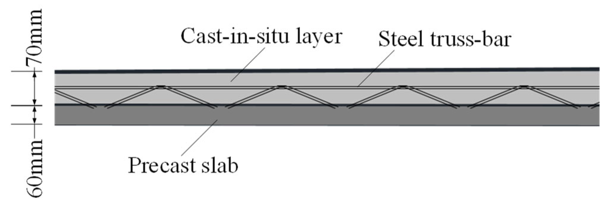
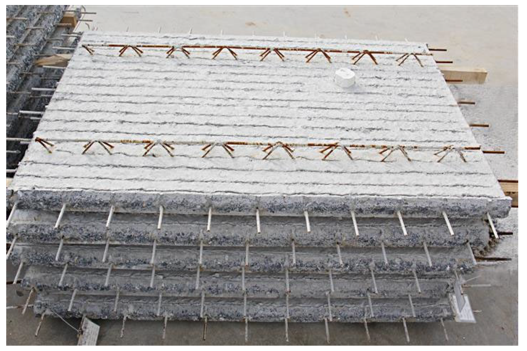
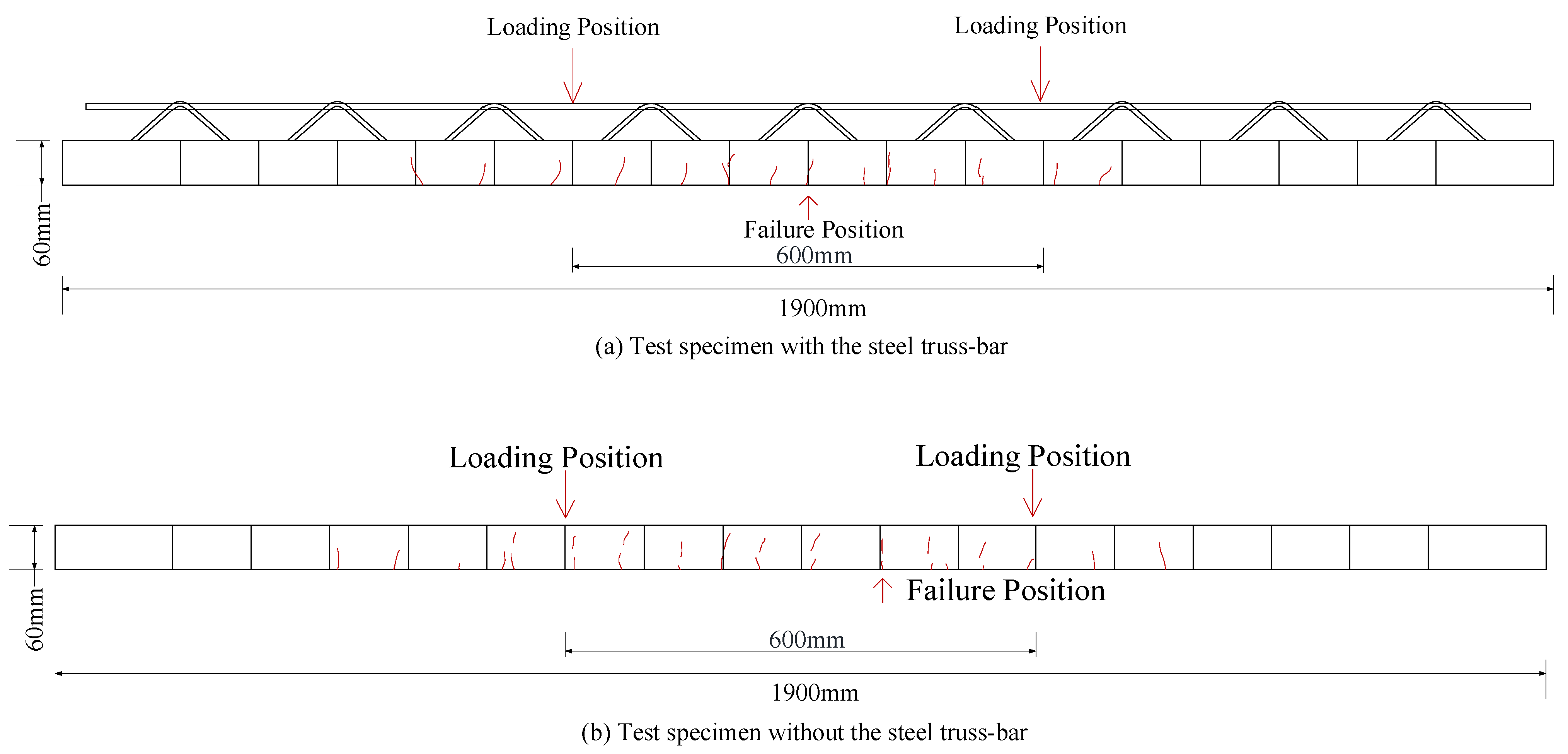
2.1. Specimens and Materials

In this paper, two sets of specimens are tested: one with a steel truss bar and one without a steel truss bar. The samples are designed according to the JGJ 1-2014 [13]. Each group included two identical specimens to reduce testing errors (Table 1). The designation PS in the specimen’s name indicates an ordinary precast slab without a steel truss bar, which is used as a reference, and the symbol PS-T refers to a precast slab with a steel truss bar. In the PS group, the bottom chord bar of the steel truss bar was also included to ensure that the area of tensile reinforcement is consistent. Each sample was 1900 mm long, 600 mm wide, and 60 mm thick. The reinforcement mesh was HRB400 ϕ8 @130 and HRB400 ϕ8 @200 bars in the longitudinal and transverse directions, respectively. The top chord, bottom chord, and web reinforcement bars were HRB400 ϕ10, ϕ8, and HPB300 ϕ6, respectively. The structural arrangement of the specimens is shown in Figure 3. Grade C30 concrete was adopted, and the strength parameters of the materials used are shown in Table 2 and Table 3.

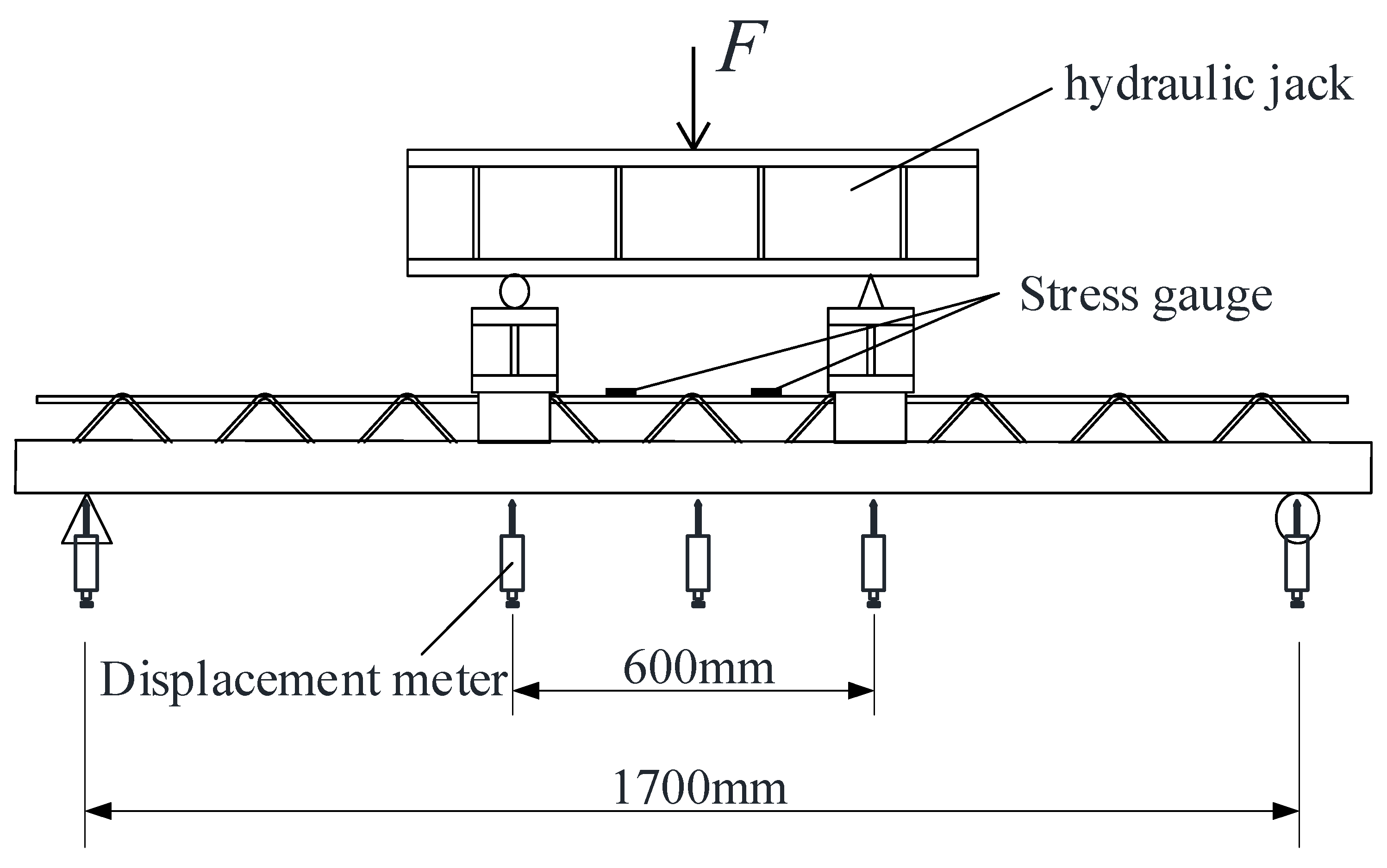
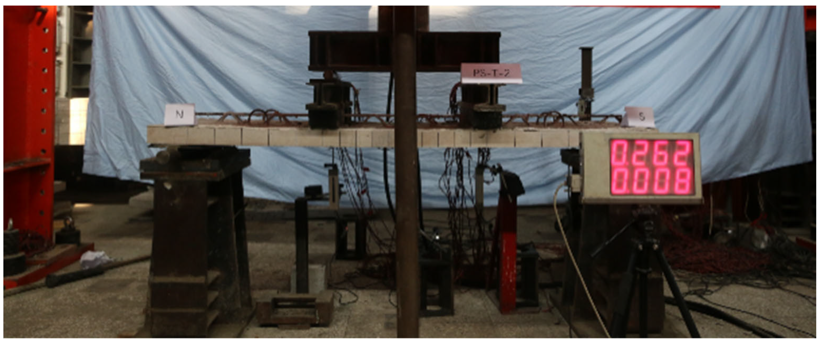
2.2. Loading Test Plan

The tests were carried out using four-point bending loading. The span of the slab between the supports was 1700 mm, and the length of the part subjected to pure bending in the middle was 600 mm (Figure 4). Displacement gauges were installed at the midspan, directly below the two loading points, and at the supports. Strain gauges were arranged on the upper surface of concrete in the pure-bending section and the upper chord reinforcement (Figure 5). A hydraulic jack was used to apply the load, and the magnitude of the load was initially controlled. When the displacement reached 30 mm, at which point the load stopped increasing noticeably, the displacement was controlled.

3. Analysis of the Test Results

3.1. Qualitative Behavior of Samples during Tests

The load–deflection curves for the two sets of specimens are shown in Figure 6. It can be seen that the load–deflection curves of the two groups of specimens are markedly different. In general, the curves of the slabs without the steel truss bar show the typical bending behavior of reinforced concrete members, which can be divided into the three stages of pre-cracking, cracking, and yielding of tensile steel. However, the load–deflection curves of the slab with the steel truss bar do not have such clear stages.
The load applied by the jack to the two types of slabs when they cracked was similar, i.e., 2.5 kN and 2.0 kN for the slabs with the steel truss bar and the slabs without the steel truss bar, respectively. As the weight of the load distribution beams was 2 kN, the actual cracking loads were 4.5 kN and 4.0 kN, respectively, while the cracking moments were 1.237 kNm and 1.100 kNm. Since the cracking loads of the two groups of specimens were similar, we can conclude that the steel truss bar had little effect on the cracking loads of the slabs.
The initial cracks generally appeared directly beneath the loading points and at the midspan. After cracking of the slabs, the specimens without the steel truss bar showed an obvious transition in behavior, where the deflection increased faster and the curve continued to rise linearly. For specimens with the steel truss bar, the load–deflection curves showed no clear transition after cracking and were highly nonlinear. At the end of the test, the two groups of specimens failed via crushing of the concrete in the pure-bending section. The upper chord truss bars in the pure-bending section experienced significant out-of-plane buckling deformations in the experimental group with the steel truss bar, which preceded the crushing of the concrete’s surface.

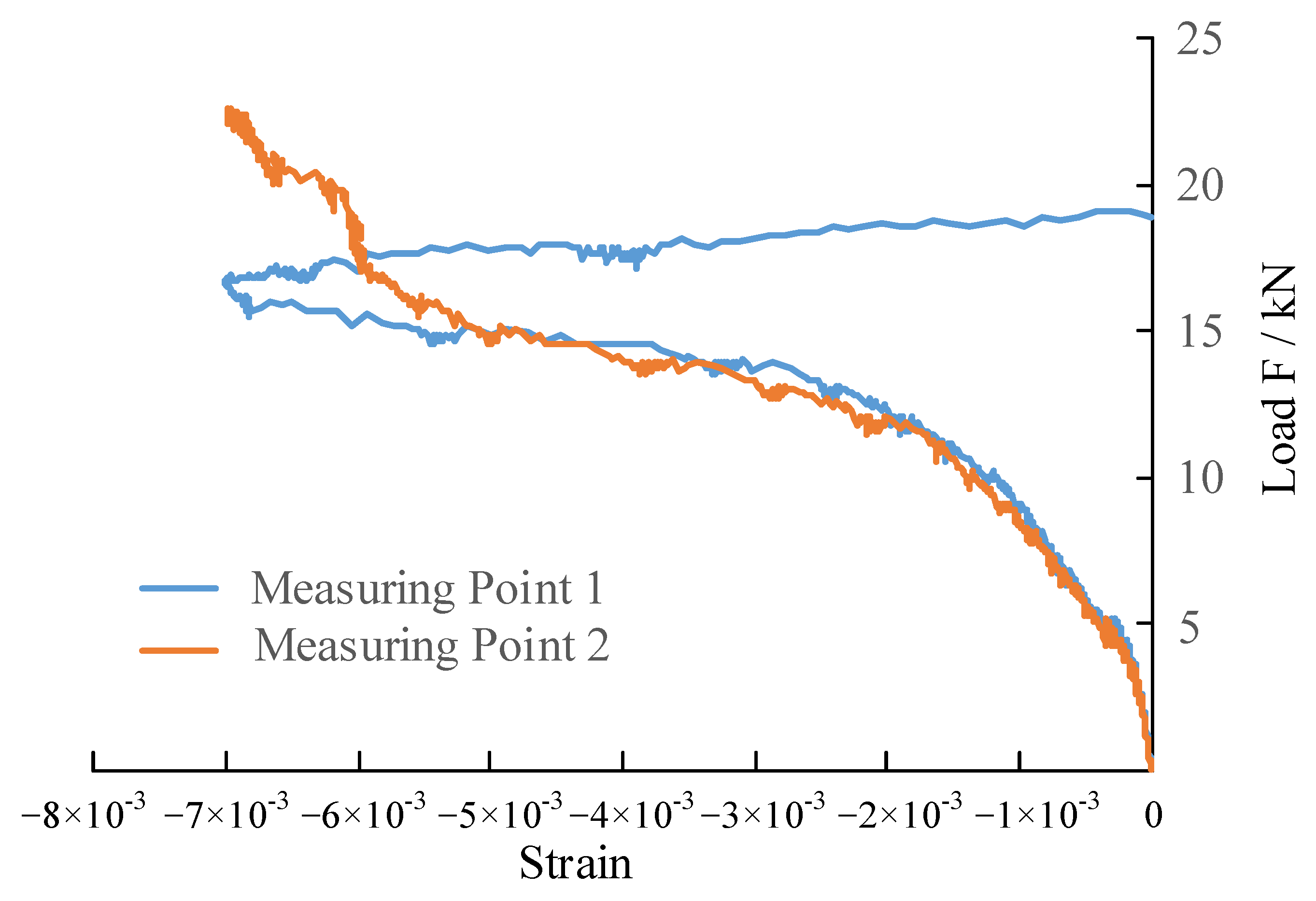
3.2. Behavior of the Steel Truss Bars

Figure 7 shows the strain developing at the two measurement points of the top chord bar in one of the specimens; the load is normalized in this figure with respect to the Fmax, which represents the ultimate load-bearing capacity of the specimen. The results show that the top chord bar yielded first and then buckled (here, the strain is 5000–6000 με when the buckling starts). Furthermore, the value of steel deformation corresponding to the boundary of the plane is 20 mm according to the experimental record.
As shown in Figure 7, the development of strain in the top chord bar can be divided into four stages:
(1)
Before the cracking of the concrete slab (load less than 0.2 Fmax), the compressive strain in the steel truss bar grew slowly, and the steel truss bar contributed little to the stiffness of the precast slab.
(2)
After the concrete slab cracked (0.2 Fmax–0.5 Fmax), the strain in the top chord bar increased significantly. The contribution of the steel truss bars to the overall strength of the precast slab increased.
(3)
According to the material test results, the steel bar started yielding when the strain reached 2000 με (0.5Fmax–0.62Fmax), and its effect on the stiffness and load-bearing capacity of the slab could be ignored thereafter.
(4)
After the buckling of the top chord bar (≥0.62Fmax), the out-of-plane deformation gradually increased. When the strain reached 6000 με, the strains at the two measurement points diverged, indicating that the bar started to display obvious plastic buckling in different directions at this time.

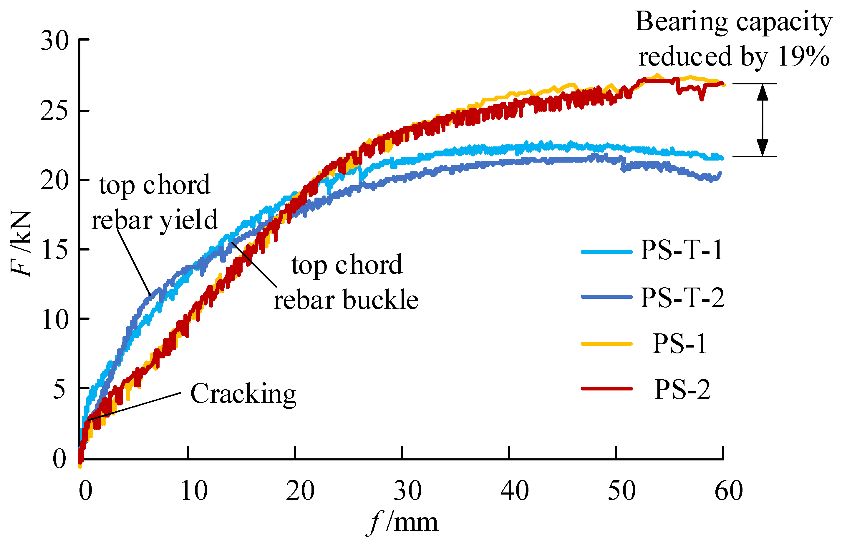
3.3. Comparison of Load-Bearing Capacity and Stiffness

The main mechanical properties of the specimens are shown in Table 4. These data present the averages for the two groups of test specimens. Adding the steel truss bars resulted in limited improvement in the cracking load and elastic stiffness of the specimens but significantly reduced the ultimate bearing capacity of the precast slab by 19%. The ultimate bearing capacity of the slabs with the steel truss bar was lower than that of the precast slabs without the steel truss bar, which could not be predicted using existing theoretical models. It is generally believed that slabs with and without the steel truss bars have the same ultimate load-bearing capacity because even if the steel truss bar buckles, the concrete slab will remain intact.
The test results indicate that the steel truss bar will reduce the ultimate load-bearing capacity of the precast slab. The main reason for this reduction is that the deformation of the top chord after buckling (Figure 8) will be transmitted to the concrete through the web bars such that the concrete in this area will be in a multi-directional stress state, leading to a reduction in the unidirectional compressive strength of the concrete.

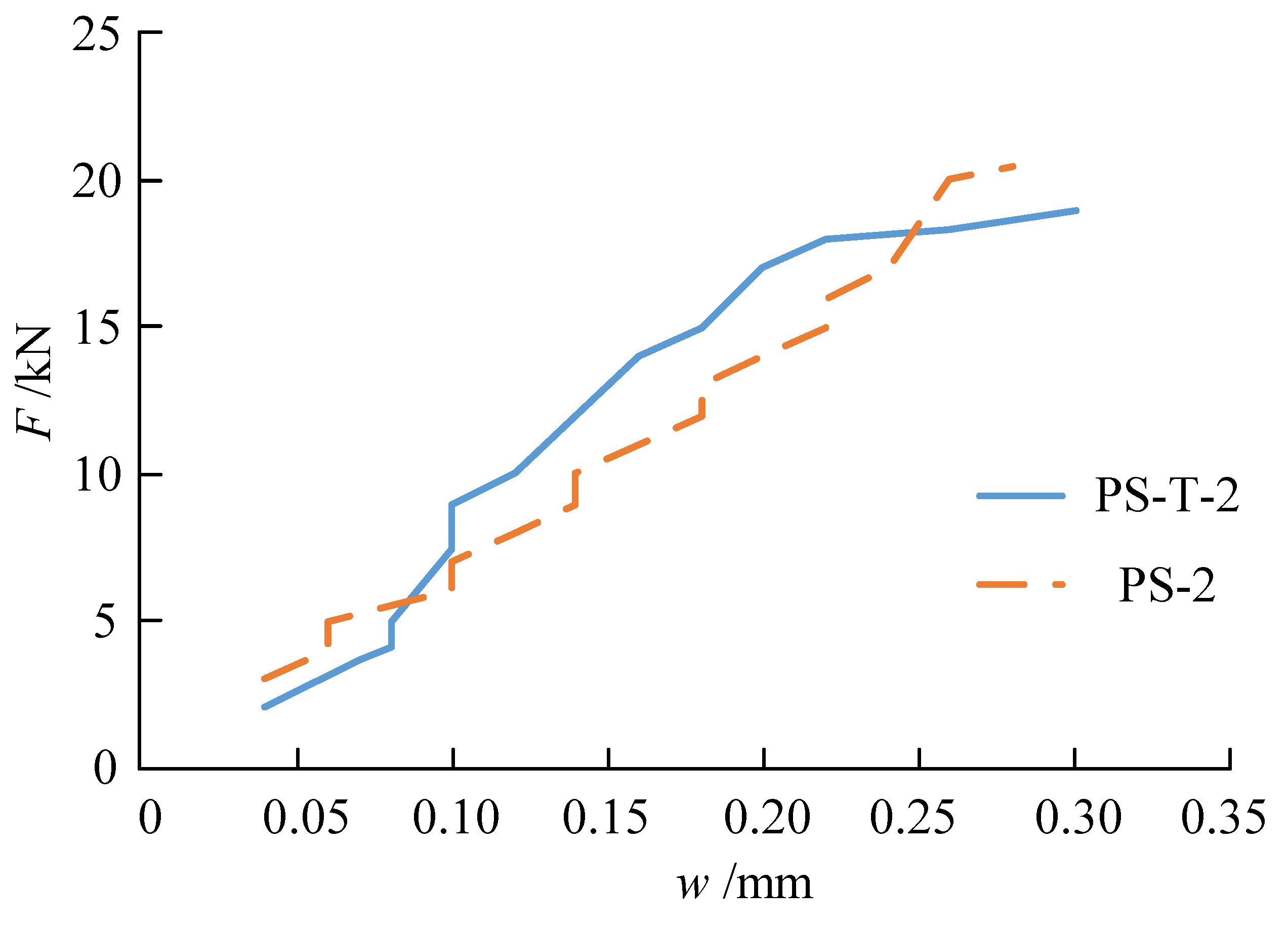
3.4. Comparison of Crack Development

The first crack generally appeared under the two loading points or across the span. After all cracks appeared, the average crack spacing of the cracks was found to be 6–8 mm, which represents the distance between two cracks. Figure 9 presents a comparison of the crack distribution of two specimens after the cracks appeared. Here, the spacing between the cracks is approximately 100 mm. Figure 10 shows a comparison of the crack width growth, which was essentially the same for the two specimens. The presence of the steel truss bar had almost no effect on the growth of the crack width of the precast slabs.

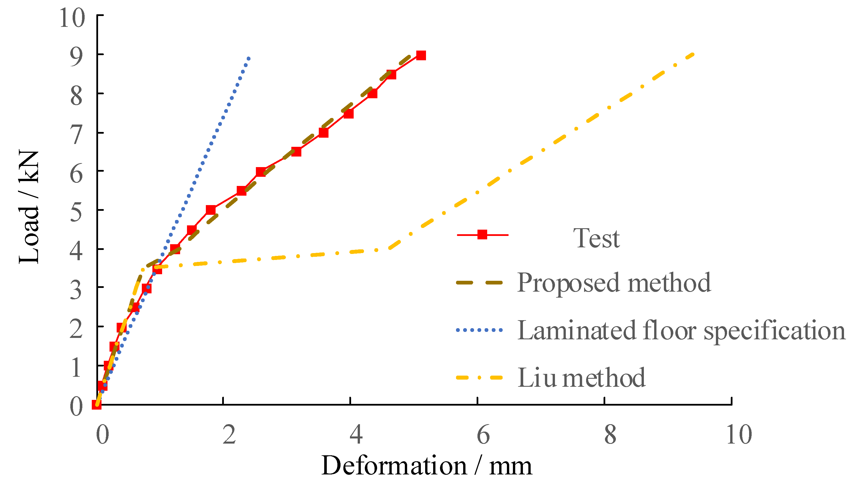
4. Calculation Method for a Slab with a Steel Truss Bar

There are currently two main methods for calculating the stiffness of precast slabs with a steel truss bar, as outlined in the following.
(1)
The code for composite slab design and construction (CECS273:2010) [14], referred to hereafter as “Laminated floor specification”, adopts the average stiffness of cracked and non-cracked sections as the overall section stiffness:
B s = E c I e q s
I e q s = I u s + I c s 2
where B s is the short-term stiffness of the flexural memberthe short-term stiffness of the flexural member under the standard combination of load effects; I e q s is the converted moment of inertia of the average section under a short-term load; I u s , I c s represent the converted moment of inertia of the uncracked section and cracked section, respectively, under a short-term load; and E c is the elastic modulus of concrete.
(2)
Liu [15] proposed a stiffness calculation method for precast concrete laminated slabs with steel truss bars based on three assumptions.
The first assumption is that the steel truss bar is very high, and, therefore, the neutral axis is located above the precast slab after cracking. Only the contribution of the longitudinal steel bar to the stiffness of the precast section is considered, and the contribution of the precast concrete layer is ignored. The moment of inertia of the section with the steel bar can then be calculated using the standard stiffness calculation methods.
The second assumption when considering the contribution of longitudinal steel bars and the precast concrete layer to the stiffness of precast members, without considering the cracking effects of concrete, calculates stiffness by taking the moment of inertia for the converted section and multiplying it by the plastic coefficient of 0.85.
The third assumption considers the influence of cracks, which results in the following calculation formulas:
B s 1 = h t 0 2 γ 1 + α 1 + β
α = h t 0 2 y 10 c D 2 2
β = 1 h t 0 H + y 10 2 c D 2 2 1
γ = α A s E s + β A s E s
where h t 0 is the distance between the top and bottom chord bar axes, D 2 is the diameter of the bottom chord bar, c is the thickness of the concrete cover layer, H is the thickness of the precast slab, y 10 is the distance converted from the centroid of the section to its lower edge, and A s is the cross-sectional area of the top chord.
Other researchers have also proposed calculation methods for slabs with steel truss bars. For example, Zhou [16] and Zhao [17] directly used the converted moment of inertia for the cracked section to calculate section stiffness, but this method only applies for stiffness after the slab is cracked. Li et al. [9] used the combined stiffness method and proposed the formulas   B s = α B u s + β B u s and B s = α + β = 1 , where α , β are calibrated according to the experimental results. However, coefficients α and β in the combined stiffness method are different for different types of structural components and require costly experimental calibrations.
In this paper, a new method is used. The basic assumption of this method is that the exposed height of the steel truss bars in construction practice is 43 mm, while the spacing is 600 mm. For these dimensions, the top chord bar has little effect on the position of the neutral axis. Therefore, the effect of the steel truss bar on the height of the neutral axis can be ignored.
When the influence of the steel truss bar on the position of the neutral axis is ignored, the coupling force between the steel truss bar and precast slab can also be ignored. Then, the short-term stiffness of the steel truss bar slab can be calculated by separately calculating and superimposing the stiffness of the steel truss bar and precast slab. The specific calculation method is introduced in the following section, while the meaning of each variable in the formulas is explained in Figure 11.
(1)
When the bending moment M is less than the cracking bending moment Mcr1, we use the following formula:
B s = 0.85 E c I + E s A s H t H 2 2 .
(2)
When the bending moment M is greater than the cracking bending moment Mcr1, we use the following formula:
The stiffness of the precast slab after cracking is related to the load, but how the load is shared between the precast slab and the steel truss bar depends on the stiffness ratio of the slab and the steel truss bar. If the precast slab and the steel truss bar are separated, some errors will be introduced, but an iterative method can be used to improve the solution.
The iteration of the separation method proceeds as follows:
(1)
Calculate the height of the neutral axis, x, of the slab without the steel truss bar using the following equation:
b H x 2 3 = A s 1 x c 1 + A s 2 x c 2
where As1 is the area of longitudinal steel bars in the slab, and As2 is the area of the bottom chord bars in the steel truss bar;
(2)
Calculate the moment of inertia for the top chord of the steel truss bar with respect to the neutral axis;
(3)
Calculate the short-term stiffness, Bs1, of the slab without the steel truss bar according to the “Specification for Design of Concrete Structures” (GB50010-2010) [18], assuming that the bending moment M is entirely borne by the precast slab;
(4)
Calculate the approximate stiffness of the slab with the steel truss bar as B s = B s 1 + E s I s ;
(5)
The method for one iteration is as follows:
Calculate the height of the neutral axis of the slab without the steel truss bar and the height, x, of the neutral axis using Equation (8);
Calculate the moment of inertia for the top chord steel truss bar with respect to the neutral axis;
Calculate the short-term stiffness, Bs1, of the slab without the steel truss bar, assuming that the bending moment M is entirely borne by the precast slab, using Equation (3);
Perform the first iteration and obtain the bending moment shared by the precast slab: M 2 = M × B s 1 / B s 1 + E s I s ;
Calculate the section stiffness of the precast slab, Bs2, under bending moment M2 using Equation (3);
Calculate the approximate stiffness of the slab with the steel truss bar using B s = B s 2 + E s I s .
The three methods of stiffness calculation discussed in this paper are listed in Table 5, and the load–displacement curves calculated using these methods, along with the experimental results, are compared in Figure 12. The calculation results show that there is no suitable method for current specifications to predict the behavior of a slab with a steel truss bar. The laminated floor specifications and Liu’s method are no longer accurate after the slab cracks, but the proposed method can accurately predict the development of slab stiffness during the entire process of cracking.

5. Discussion on the Practicality of Using Steel Truss Bar Slabs

The test results show that because the steel truss bars adopted in construction practice are relatively small in height, improvements in the cracking load and stiffness of precast slabs remain very limited. This factor also reduces the ultimate load-bearing capacity of the precast slab. In addition, after installing a steel truss bar, the cost of reinforcing the entire floor slab increases significantly. From the perspective of engineering practice, the practicality of using a steel truss bar slab and the feasibility of eliminating this type of slab will be discussed in this section through calculations and comparisons.
In the selected case study, the thickness of the precast slab was 60 mm with a 70 mm cast in situ layer, the slab span was 3 m, the longitudinal reinforcement of the precast slab was ϕ8 @150, the thickness of the concrete cover was 15 mm, and the spacing of the steel truss bars was 600 mm. Temporary support was not used during construction. The self-weight of the floor slab was 3.25 kN/m2, and the construction live load was 1.5 kN/m2. The deflection limit was determined according to the requirements of the code for composite slab design and construction.14 Under the action of the slab’s self-weight and construction live load, the deflection of the precast slab should be lower than the lesser of L0/180 (where L0 represents the effective span of the precast slab) and 20 mm, which is 16.7 mm.
Table 6 lists the deflections of the precast slabs in the construction stage based on the test results and the stiffness calculation method proposed in this paper. The results show that the 3 m slab cannot self-support itself irrespective of whether the steel truss bar is used and temporary support is required. However, after using temporary supports, the deformation of the two types of precast slabs can be ignored, as the stiffness of the slabs can be increased without using steel truss bar reinforcements.
The relationship between the deflection and span length for the slab with and without the steel truss bar is plotted in Figure 13. The calculation results show that if a 60 mm thick precast slab without a steel truss bar is used, the stiffness does not meet the requirements when the span exceeds 2.5 m; if a steel truss bar is installed, the deflection will also exceed the limit when the span exceeds 2.75 m, i.e., adopting a steel truss bar increases the span limit of the slab by only 10%.
The relationships between the deflection and span length of 70 mm and 80 mm thick precast slabs are also shown in Figure 13. It can be seen that the stiffness of the 70 mm thick precast slab without the steel truss bar is practically the same as that of the 60 mm thick slab, and the stiffness of the 80 mm thick precast slab is clearly higher than that of the 60 mm thick slab. Here, the maximum achievable slab span is 3.2 m.
A comparison of performance indicators for the various precast slabs is listed in Table 7. It can be seen that for the 60 mm thick precast slab, the installation of the steel truss bar only increased the design span by 10%, while the load-bearing capacity decreased by 20%. When the slab thickness was increased to 70 mm, even if no steel truss bar was provided, the design span remained the same as that of the 60 mm thick slab with the steel truss bar. However, the load-bearing capacity increased by 51%, and the steel consumption reduced by 26%. When the slab thickness was further increased to 80 mm, compared to the 60 mm thick slab with the steel truss bar commonly used in construction practice, the precast slab without the steel truss bar featured significantly improved stiffness, design span, and ultimate load-bearing capacity with significantly reduced steel consumption.
Taking into account Article 6.6.2 of JGJ 1-2014 [13], the thickness of cast in situ concrete should not be less than 60 mm. For a typical 130 mm laminated slab floor, a 70 mm thick steel slab without a steel truss bar alongside a 60 mm thick cast in situ concrete layer is recommended. If future experiments prove that an 80 mm thick slab without a steel truss bar plus a 50 mm thick cast in situ concrete layer can ensure the required integrity and design performance of floor structures for spans exceeding 3 m, an 80 mm thick slab without a steel truss bar could be considered for use in precast construction.

6. Conclusions

In this paper, the effects of steel truss bars on the mechanical properties of precast slabs in prefabricated structures were analyzed. The main conclusions are as follows:
(1)
An improvement in the stiffness and cracking load of the precast slab achieved by adding a steel truss bar was found to be negligible;
(2)
Installation of a steel truss bar will weaken the compression section of the concrete, resulting in a significant reduction in the ultimate bearing capacity of the precast slab;
(3)
The top chord bar of the steel truss bar is prone to buckling, and the load-bearing capacity drops immediately after the precast slab reaches its limit;
(4)
The stiffness of the slab with a steel truss bar can accurately be predicted using the method proposed in this study;
(5)
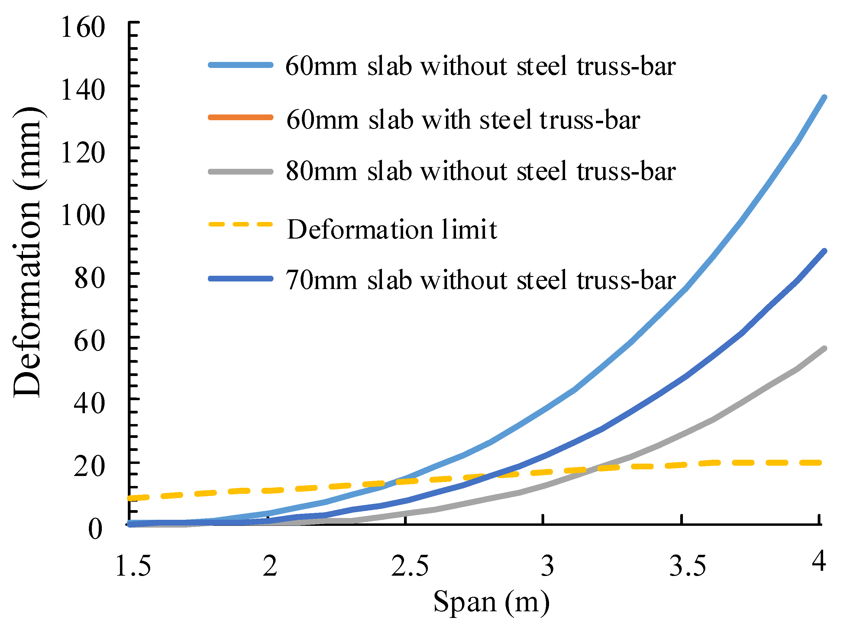
Increasing the slab’s thickness is a more effective method for improving the mechanical properties of precast slabs and reducing the manufacturing costs than adding a steel truss bar;
(6)
When using 70 mm thick precast slabs without a steel truss bar, the maximum design span was the same as that of the 60 mm thick slab with a steel truss bar, the ultimate load-bearing capacity increased by 51%, and the consumption of steel reduced by 26%. Therefore, it is recommended to use 70 mm thick precast slabs without steel truss bars instead of 60 mm thick precast slabs with steel truss bars in practical engineering applications.
Future work could focus on the mechanical performance of new types of precast slabs, such as slotted precast slabs, and the slotted form could be used to replace the setting of steel truss reinforcements.

Author Contributions

Conceptualization, G.X.; methodology, G.L.; Writing, J.Z.; supervision, Z.Z. All authors have read and agreed to the published version of the manuscript.

Funding

This research received no external funding.

Institutional Review Board Statement

Not applicable.

Informed Consent Statement

Informed consent was obtained from all subjects involved in the study.

Data Availability Statement

Some or all data, models, or code that support the findings of this study are available from the corresponding author upon reasonable request.

Conflicts of Interest

The authors declare no conflict of interest.

Nomenclature

A s Cross-sectional area of the top chord
As1The area of longitudinal steel bars in the slab
As2The area of the bottom chord bars in the steel truss bar
BsShort-term stiffness of the flexural member under the standard combination of load effects
c Thickness of the concrete cover layer
D 2 Diameter of the bottom chord bar
E c Elastic modulus of the concrete
FmaxThe ultimate load-bearing capacity of the specimen
h t 0 Distance between the top and bottom chord bar axes
HThickness of the precast slab
I e q s Converted moment of inertia of the average section under short-term load
I u s Converted moment of inertia of the uncracked section under short-term load
I c s Converted moment of inertia of the cracked section under short-term load
L0Effective span of the precast slab
MBending moment
Mcr1Cracking moment
xThe height of the neutral axis of the slab
y 10 Converted distance from the centroid of the section to its lower edge
α Coefficients of the combined stiffness method
β Coefficients of the combined stiffness method

References

  1. Russell, H.G.; Ralls, M.L.; Tang, B.M. Prefabricated bridge elements and systems in Japan and Europe. Transp. Res. Rec. J. Transp. Res. Board 2005, 1928, 102–109. [Google Scholar] [CrossRef]
  2. Hällmark, R.; White, H.; Collin, P. Prefabricated Bridge Construction across Europe and America. Pract. Period. Struct. Des. Constr. 2012, 17, 82–92. [Google Scholar] [CrossRef]
  3. Li, Y.P.; Wang, W. Problems and countermeasures in the development of prefabricated building. J. Eng. Manag. Sci. 2016, 30, 1–5. [Google Scholar]
  4. Li, L.; Xiao, Z.; Fu, X.; Yang, X. Analysis on Construction Cost of Prefabricated Building. Constr. Econ. 2014, 35, 63–67. [Google Scholar]
  5. Li, X.M. Development and application of key technology of prefabricated concrete structure in foreign countries. Hous. Ind. 2011, 6, 16–18. [Google Scholar]
  6. Li, Y.X.; Jiang, L.; Yu, Z.Q.; Li, J.; Li, Y.W. Test Research on the Behaviors of Steel Bar Truss and Concrete Superimposed Floor Slabs. Appl. Mech. Mater. 2012, 166–169, 3–8. [Google Scholar] [CrossRef]
  7. Li, J.; Yu, Q.; Zhou, Y. Research on Calculation Method for Bending Stiffness of a New Type of Steel Bar Truss Concrete Superimposed Slab. Build. Ence 2016, 9, 8–13. [Google Scholar] [CrossRef]
  8. Tang, L.; Guo, Z.; Ding, G. Structural Performance Test Research on The New Steel Bar Truss Concrete Superimposed Two-Way Slab. Ind. Constr. 2013, 11, 49–53. [Google Scholar]
  9. Li, J.; Huang, P.; Chen, Y.; Jiang, L.; Yu, Z.; Jia, Z. Experimental Research on Mechanical Properties of Self-sustaining Steel Bar Truss and Concrete Superposed Slab. Struct. Eng. 2013, 4, 132–139. [Google Scholar] [CrossRef]
  10. An, H.; Jia, L.; Ding, Y. Experimental research on mechanical performance of two-way prestressed laminated concrete slab and its application. Build. Struct. 2012, 42, 90–93. [Google Scholar]
  11. Li, M.; Sun, Z.Z.; Zhao, W.J.; Liu, Y. Research Progress on Reinforced Concrete Laminated Slab in China. Appl. Mech. Mater. 2012, 174–177, 263–267. [Google Scholar] [CrossRef]
  12. Wang, B.; Han, J. Study on Flexural Behavior of Pre-Stressed Concrete Hollow Slabs Strengthen with CFRP. Appl. Mech. Mater. 2014, 446–447, 1413–1416. [Google Scholar] [CrossRef]
  13. JGJ 1-2014; Technical Specification for Precast Concrete Structures. China Architecture & Building Press: Beijing, China, 2010.
  14. CECS 273:2010; Code for Composite Slabs Design and Construction. China Planning Press: Beijing, China, 2010.
  15. Liu, Y. Performence Research of Steel Bar Truss and Concrete Composite Slab. Ph.D. Thesis, Zhejiang University, Hangzhou, China, 2006. [Google Scholar]
  16. Zhou, Y. Research on the Mechanical Properties of the New Type of Steel Bar Truss Concrete Superimposed Slab. Ph.D. Thesis, Zhengzhou University, Zhengzhou, China, 2016. [Google Scholar]
  17. Zhao, L. Research on Design and Calculation Method of Self-Supporting R.C. Truss Rebar Composite Slab. Ph.D. Thesis, Central South University, Changsha, China, 2007. [Google Scholar]
  18. GB50010-2010; Code for Design of Concrete Structures. China Architecture & Building Press: Beijing, China, 2010.
Figure 1. Structure of a partially precast slab with a steel truss bar.
Buildings 13 01653 g001
Figure 2. Precast concrete slab with steel truss bars.
Buildings 13 01653 g002
Figure 3. Details of the experimental slabs.
Buildings 13 01653 g003
Figure 4. Sketch of the test setup.
Buildings 13 01653 g004
Figure 5. Photo of the test setup.
Buildings 13 01653 g005
Figure 6. Experimental load–deflection curves.
Buildings 13 01653 g006
Figure 7. Strain development in the top chord bars.
Buildings 13 01653 g007
Figure 8. Top chord buckling.
Buildings 13 01653 g008
Figure 9. Crack width growth with load.
Buildings 13 01653 g009
Figure 10. Crack distribution comparison.
Buildings 13 01653 g010
Figure 11. Geometry of a slab.
Buildings 13 01653 g011
Figure 12. Comparison of stiffness calculations of the precast slab with a steel truss bar.
Buildings 13 01653 g012
Figure 13. Change of deflection with span length during the construction stage.
Buildings 13 01653 g013
Table 1. Specimen parameters.
GroupNo.Length/mmWidth/mmThickness/mmTruss Bar
TestPS-T-1190060060yes
PS-T-2190060060yes
ReferencePS-1190060060no
PS-2190060060no
Table 2. Mechanical properties of concrete.
fcu,m */MPafc,m **/MPafc,k ***/MPa
37.228.324.9
* fcu,m is the average value of the compressive strength of concrete cubes; ** fc,m is the average value of the axial compressive strength of concrete; *** fc,k is the standard value of the axial compressive strength of concrete.
Table 3. Mechanical properties of steel.
DiameterGradefy */MPafu **/MPa
8HRB400399.9666.5
10HRB400407.4643.0
* fy is the yield strength; ** fu is the ultimate strength.
Table 4. Key experimental mechanical indicators.
GroupCracking Moment
Mc/kNm
Elastic Stiffness
EII/kN*m2
Ultimate Bending Moment
Mu/kNm
PS1.100424.47.43
PS-T1.237488.56.03
Difference0.13764.1−1.40
13%15%−19%
Table 5. Calculation methods for short-term stiffness.
ReferenceEquation
Laminated floor specifications [14] B s = E c I e q s ; I e q s = I u s + I c s 2
Liu [15] B s = h t 0 2 γ 1 + α 1 + β
Method proposed in this paper B s = B s 2 + E s I s
Table 6. Comparison of deflections during the construction stage (numerical study).
Precast Slab Self-Weight g1 = 25 × 0.06 = 1.5 kN/m2
Cast In Situ Layer Weight g2 = 25 × 0.07 = 1.75 kN/m2
Construction Load w = 1.5 kN/m2
3 m span slab without support3 m span slab with a support in the middle
Deflection/mm Deflection/mm
Slab with steel truss bar20Slab with steel truss bar0.2
Slab without steel truss bar35Slab without steel truss bar0.2
Table 7. Comparison of floor performance.
Maximum Self-Supported Slab Span/mUltimate Load-Bearing Capacity during Construction/(kNm/m)Steel Consumption/(kg/m2)
60 mm slab with truss bar *2.75 (100%)4.39 (100%)12.5 (100%)
60 mm slab without truss bar2.45 (89%)5.27 (120%)9.2 (73.6%)
70 mm slab without truss bar2.75 (100%)6.61 (151%)9.2 (73.6%)
80 mm slab without truss bar3.2 (116%)7.95 (181%)9.2 (73.6%)
* The values in parentheses represent percentage ratios with respect to a 60 mm slab with steel truss.
Disclaimer/Publisher’s Note: The statements, opinions and data contained in all publications are solely those of the individual author(s) and contributor(s) and not of MDPI and/or the editor(s). MDPI and/or the editor(s) disclaim responsibility for any injury to people or property resulting from any ideas, methods, instructions or products referred to in the content.

