

Metal–Organic Frameworks (MOFs) Based Electrospun Nanofiber Membrane for Passive Indoor Moisture Control


Abstract
1. Introduction
2. Materials
2.1. Preparation of MIL-100(Fe)
2.2. Preparation of MIL-100(Fe) NFM
2.3. Preparation of MIL-100(Fe)@LiCl NFM
3. Characterization
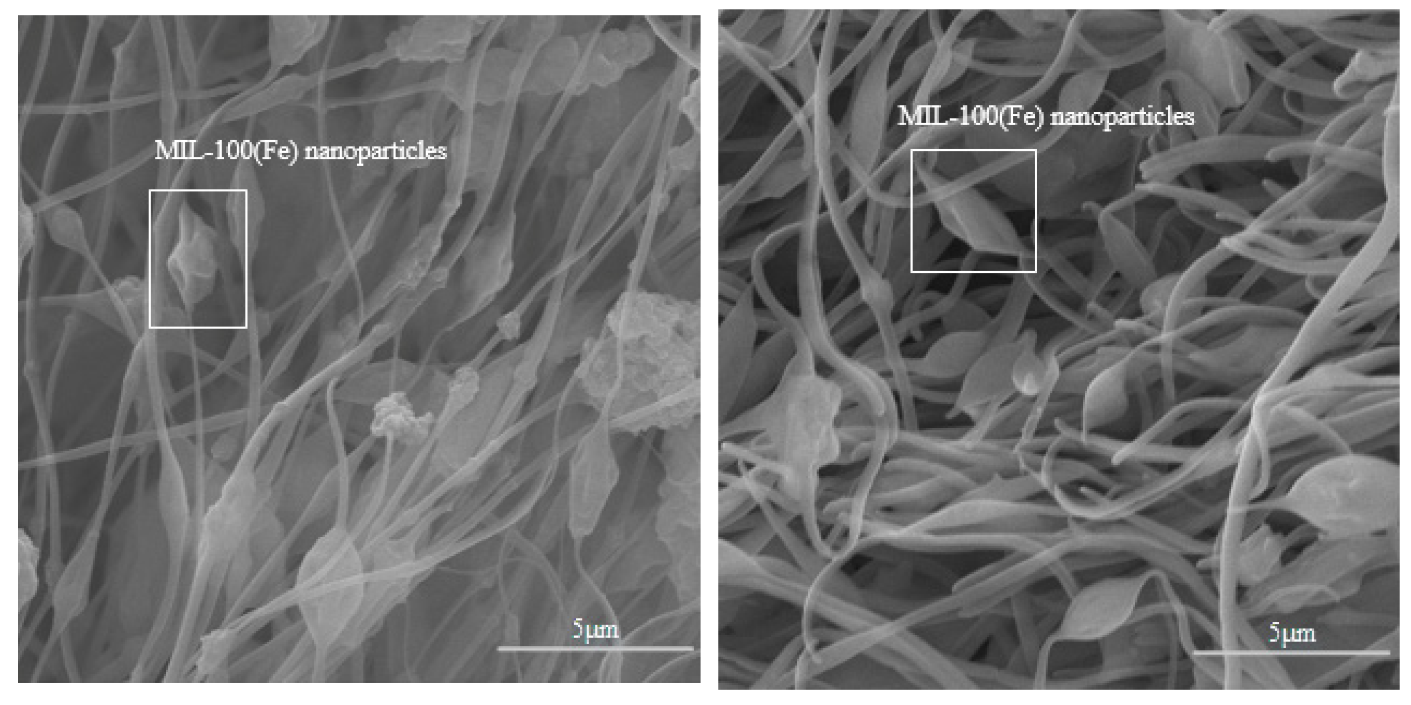
3.1. Micromorphology and Chemical Characterization
3.2. Hygric Properties
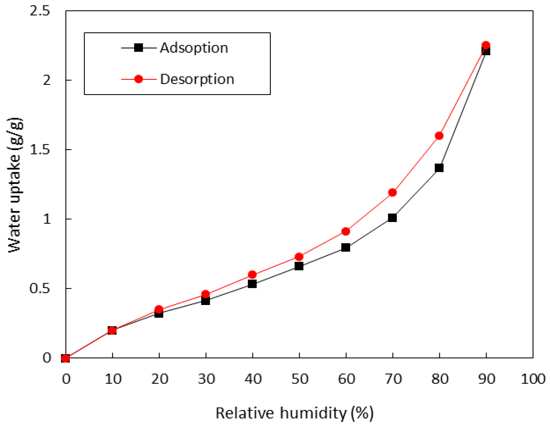
3.2.1. Water Vapor Sorption Isotherms
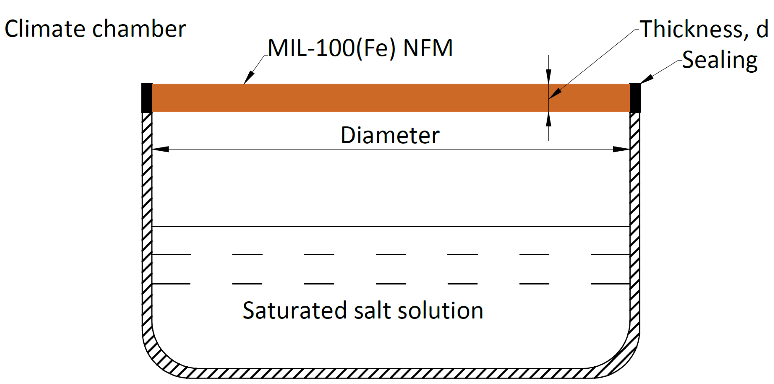
3.2.2. Deliquescence Test
3.2.3. Water Vapor Transfer Coefficient
3.3. Cycling Performance of MOF NFM
4. Energy-Saving Potential
4.1. Indoor Moisture and Building Energy Simulation
- The air temperature is constant within each zone: the temperature and humidity are the same throughout the room, and the air is thoroughly mixed.
- Heat and moisture transfer processes through components are considered to be one-dimensional. Consequently, the entire surface of each component has a constant temperature. Due to the one-dimensional approach to the component, direct interactions over the components’ boundaries or inhomogeneous components in between the different materials are not considered.
- Physical material properties are not time-dependent.
4.2. Test Building
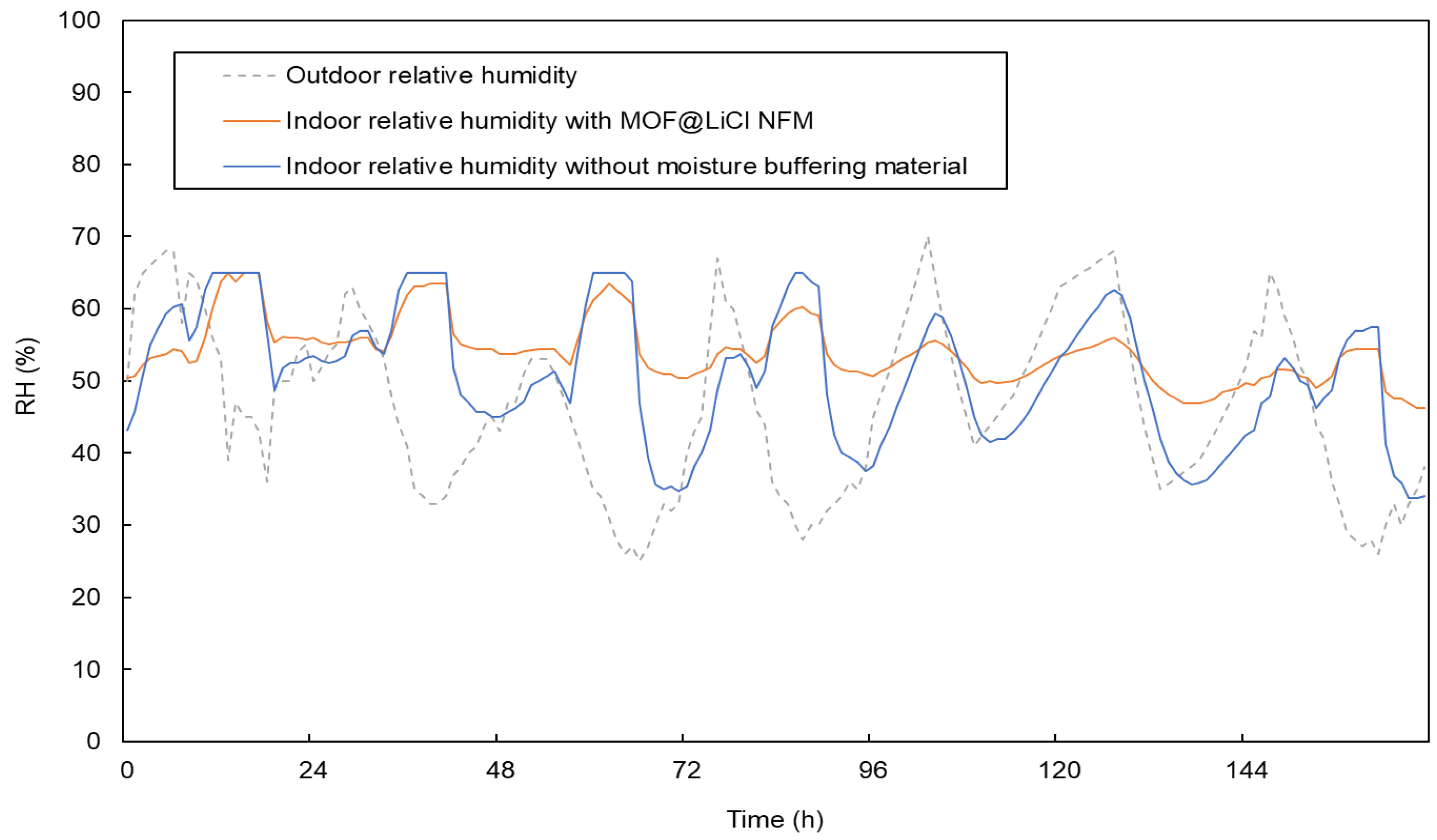
4.3. Simulated Indoor Relative Humidity
4.3.1. Phoenix (Hot Desert Climate)
4.3.2. Madrid (Mediterranean Climate)
4.3.3. Paris (Temperate Climate)
5. Conclusions
Author Contributions
Funding
Institutional Review Board Statement
Informed Consent Statement
Data Availability Statement
Acknowledgments
Conflicts of Interest
References
- United Nations Environment Programme. Buildings and Climate Change: Status, Challenges and Opportunities; United Nations Environment: Nairobi, Kenya, 2007. [Google Scholar]
- IEA. The Future of Cooling; International Energy Agency Technical Report; IEA: Paris, France, 2018. [Google Scholar]
- Zeng, Y.; Woods, J.; Cui, S. The energy saving potential of thermo-responsive desiccants for air dehumidification. Energy Convers. Manag. 2021, 244, 114520. [Google Scholar] [CrossRef]
- Chen, Y.; Ozaki, A.; Lee, H. Energy saving potential of passive dehumidification system combined with energy recovery ventilation using renewable energy. Energy Build. 2022, 268, 112170. [Google Scholar] [CrossRef]
- Chua, K.; Chou, S.; Yang, W.; Yan, J. Achieving better energy-efficient air conditioning—A review of technologies and strategies. Appl. Energy 2013, 104, 87–104. [Google Scholar] [CrossRef]
- Griffiths, W.C. Desiccant dehumidification reduces refrigeration loads. Energy Eng. 1989, 86, 39–47. [Google Scholar]
- Rambhad, K.S.; Walke, P.V.; Tidke, D.J. Solid desiccant dehumidification and regeneration methods—A review. Renew. Sustain. Energy Rev. 2016, 59, 73–83. [Google Scholar] [CrossRef]
- Kreiger, B.K.; Srubar, W.V. Moisture buffering in buildings: A review of experimental and numerical methods. Energy Build. 2019, 202, 109394. [Google Scholar] [CrossRef]
- Li, X.; Li, Z.; Xia, Q.; Xi, H. Effects of pore sizes of porous silica gels on desorption activation energy of water vapour. Appl. Therm. Eng. 2007, 27, 869–876. [Google Scholar] [CrossRef]
- Gabruś, E.; Nastaj, J.; Tabero, P.; Aleksandrzak, T. Experimental studies on 3A and 4A zeolite molecular sieves regeneration in TSA process: Aliphatic alcohols dewatering–water desorption. Chem. Eng. J. 2015, 259, 232–242. [Google Scholar] [CrossRef]
- Zhang, M.; Qin, M.; Rode, C.; Chen, Z. Moisture buffering phenomenon and its impact on building energy consumption. Appl. Therm. Eng. 2017, 124, 337–345. [Google Scholar] [CrossRef]
- Rode, C.; Holm, A.; Padfield, T. A Review of Humidity Buffering in the Interior Spaces. J. Therm. Envel. Build. Sci. 2004, 27, 221–226. [Google Scholar] [CrossRef]
- Wang, C.; Yang, B.; Ji, X.; Zhang, R.; Wu, H. Study on activated carbon/silica gel/lithium chloride composite desiccant for solid dehumidification. Energy 2022, 251, 123874. [Google Scholar] [CrossRef]
- Yang, Z.; Zhang, W.; Lin, X.; Xiong, Q.; Jiang, Q. Optimization of minor-LiCl-modified gypsum as an effective indoor moisture buffering material for sensitive and long-term humidity control. Build. Environ. 2023, 229, 109962. [Google Scholar] [CrossRef]
- Zhang, Y.; Palamara, D.; Palomba, V.; Calabrese, L.; Frazzica, A. Performance analysis of a lab-scale adsorption desalination system using silica gel/LiCl composite. Desalination 2023, 548, 116278. [Google Scholar] [CrossRef]
- Wu, Z.; Qin, M.; Zhang, M. Phase change humidity control material and its impact on building energy consumption. Energy Build. 2018, 174, 254–261. [Google Scholar] [CrossRef]
- Qin, M.; Feaugas, O.; Zu, K. Novel metal-organic framework (MOF) based phase change material composite and its impact on building energy consumption. Energy Build. 2022, 273, 112382. [Google Scholar] [CrossRef]
- Luo, F.; Liang, X.; Chen, W.; Wang, S.; Gao, X.; Zhang, Z.; Fang, Y. Solar-driven smart ceramic fiber-based monolithic adsorbent for autonomous indoor humidity control. Chem. Eng. J. 2022, 450, 138241. [Google Scholar] [CrossRef]
- Lin, Y.-W.; Lee, W.-H.; Kuo, B.-Y.; Lin, K.-L. Effect of the indoor humidity control characteristics for amine grafted functionalized mesoporous silica nanomaterials. J. Chin. Inst. Eng. 2023, 46, 11–20. [Google Scholar] [CrossRef]
- Guo, J.; Xue, X.; Yu, H.; Duan, Y.; Li, F.; Lian, Y.; Liu, Y.; Zhao, M. Metal–organic frameworks based on infinite secondary building units: Recent progress and future outlooks. J. Mater. Chem. A 2022, 10, 19320–19347. [Google Scholar] [CrossRef]
- Guo, J.; Duan, Y.; Liu, Y.; Li, H.; Zhang, Y.; Long, C.; Wang, Z.; Yang, Y.; Zhao, S. The biomimetic engineering of metal–organic frameworks with single-chiral-site precision for asymmetric hydrogenation. J. Mater. Chem. A 2022, 10, 6463–6469. [Google Scholar] [CrossRef]
- Canivet, J.; Fateeva, A.; Guo, Y.; Coasne, B.; Farrusseng, D. Water adsorption in MOFs: Fundamentals and applications. Chem. Soc. Rev. 2014, 43, 5594–5617. [Google Scholar] [CrossRef]
- Hastürk, E.; Ernst, S.-J.; Janiak, C. Recent advances in adsorption heat transformation focusing on the development of adsorbent materials. Curr. Opin. Chem. Eng. 2019, 24, 26–36. [Google Scholar] [CrossRef]
- Cui, S.; Qin, M.; Marandi, A.; Steggles, V.; Wang, S.; Feng, X.; Nouar, F.; Serre, C. Metal-Organic Frameworks as advanced moisture sorbents for energy-efficient high temperature cooling. Sci. Rep. 2018, 8, 19320–19347. [Google Scholar] [CrossRef] [PubMed]
- Zu, K.; Qin, M.; Cui, S. Progress and potential of metal-organic frameworks (MOFs) as novel desiccants for built environment control: A review. Renew. Sustain. Energy Rev. 2020, 133, 110246. [Google Scholar] [CrossRef]
- Feng, X.; Qin, M.; Cui, S.; Rode, C. Metal-organic framework MIL-100(Fe) as a novel moisture buffer material for energy-efficient indoor humidity control. Build. Environ. 2018, 145, 234–242. [Google Scholar] [CrossRef]
- Zu, K.; Qin, M. Experimental and modeling investigation of water adsorption of hydrophilic carboxylate-based MOF for indoor moisture control. Energy 2021, 228, 120654. [Google Scholar] [CrossRef]
- Harrouz, J.P.; Ghali, K.; Hmadeh, M.; Slim, R.; Katramiz, E.; Ghaddar, N. Design and control of MOFs-based indoor humidity pump integrated into the building’s ventilated façade in hot and humid climates. Energy Convers. Manag. 2022, 268, 115983. [Google Scholar] [CrossRef]
- Hou, P.; Qin, M.; Cui, S.; Zu, K. Preparation and characterization of metal-organic framework/microencapsulated phase change material composites for indoor hygrothermal control. J. Build. Eng. 2020, 31, 101345. [Google Scholar] [CrossRef]
- Ge, L.; Ge, T.; Wang, R. Facile synthesis of Al-based MOF and its applications in desiccant coated heat exchangers. Renew. Sustain. Energy Rev. 2022, 157, 112015. [Google Scholar] [CrossRef]
- Qin, M.; Hou, P.; Wu, Z.; Wang, J. Precise humidity control materials for autonomous regulation of indoor moisture. Build. Environ. 2020, 169, 106581. [Google Scholar] [CrossRef]
- Hou, P.; Zu, K.; Qin, M.; Cui, S. A novel metal-organic frameworks based humidity pump for indoor moisture control. Build. Environ. 2021, 187, 107396. [Google Scholar] [CrossRef]
- Rose, M.; Böhringer, B.; Jolly, M.; Fischer, R.; Kaskel, S. MOF Processing by Electrospinning for Functional Textiles. Adv. Eng. Mater. 2011, 13, 356–360. [Google Scholar] [CrossRef]
- Dou, Y.; Zhang, W.; Kaiser, A. Electrospinning of Metal–Organic Frameworks for Energy and Environmental Applications. Adv. Sci. 2020, 7, 1902590. [Google Scholar] [CrossRef]
- Zhang, Y.; Yuan, S.; Feng, X.; Li, H.; Zhou, J.; Wang, B. Preparation of Nanofibrous Metal–Organic Framework Filters for Efficient Air Pollution Control. J. Am. Chem. Soc. 2016, 138, 5785–5788. [Google Scholar] [CrossRef]
- Efome, J.E.; Rana, D.; Matsuura, T.; Lan, C.Q. Metal–organic frameworks supported on nanofibers to remove heavy metals. J. Mater. Chem. A 2018, 6, 4550–4555. [Google Scholar] [CrossRef]
- Ren, J.; Musyoka, N.M.; Annamalai, P.; Langmi, H.W.; North, B.C.; Mathe, M. Electrospun MOF nanofibers as hydrogen storage media. Int. J. Hydrogen Energy 2015, 40, 9382–9387. [Google Scholar] [CrossRef]
- Kim, S.; Liang, Y.; Kang, S.; Choi, H. Solar-assisted smart nanofibrous membranes for atmospheric water harvesting. Chem. Eng. J. 2021, 425, 131601. [Google Scholar] [CrossRef]
- Li, A.; Xiong, J.; Liu, Y.; Wang, L.; Qin, X.; Yu, J. A Rapid-Ab/Desorption and Portable Photothermal MIL-101(Cr) Nanofibrous Composite Membrane Fabricated by Spray-Electrospinning for Atmosphere Water Harvesting. Energy Environ. Mater. 2023, 6, e12254. [Google Scholar] [CrossRef]
- Zhang, Y.; Wu, L.; Wang, X.; Yu, J.; Bin Ding, B. Super hygroscopic nanofibrous membrane-based moisture pump for solar-driven indoor dehumidification. Nat. Commun. 2020, 11, 3302. [Google Scholar] [CrossRef]
- Jeremias, F.; Khutia, A.; Henninger, S.; Janiak, C. MIL-100 (Al, Fe) as water adsorbents for heat transformation purposes—A promising application. J. Mater. Chem. 2012, 22, 10148–10151. [Google Scholar] [CrossRef]
- Luo, Y.; Tan, B.; Liang, X.; Wang, S.; Gao, X.; Zhang, Z.; Fang, Y. Investigation on water vapor adsorption performance of LiCl@ MIL-100 (Fe) composite adsorbent for adsorption heat pumps. Int. J. Energy Res. 2020, 44, 5895–5904. [Google Scholar] [CrossRef]
- Seo, Y.-K.; Yoon, J.W.; Lee, J.S.; Lee, U.-H.; Hwang, Y.K.; Jun, C.-H.; Horcajada, P.; Serre, C.; Chang, J.-S. Large scale fluorine-free synthesis of hierarchically porous iron(III) trimesate MIL-100(Fe) with a zeolite MTN topology. Microporous Mesoporous Mater. 2012, 157, 137–145. [Google Scholar] [CrossRef]
- Fang, Y.; Wen, J.; Zeng, G.; Jia, F.; Zhang, S.; Peng, Z.; Zhang, H. Effect of mineralizing agents on the adsorption performance of metal–organic framework MIL-100(Fe) towards chromium(VI). Chem. Eng. J. 2018, 337, 532–540. [Google Scholar] [CrossRef]
- Huang, S.; Yang, K.; Liu, X.; Pan, H.; Zhang, H.; Yang, S. MIL-100(Fe)-catalyzed efficient conversion of hexoses to lactic acid. RSC Adv. 2017, 7, 5621–5627. [Google Scholar] [CrossRef]
- Canioni, R.; Roch-Marchal, C.; Sécheresse, F.; Horcajada, P.; Serre, C.; Hardi-Dan, M.; Férey, G.; Grenèche, J.-M.; Lefebvre, F.; Chang, J.-S.; et al. Stable polyoxometalate insertion within the mesoporous metal organic framework MIL-100(Fe). J. Mater. Chem. 2011, 21, 1226–1233. [Google Scholar] [CrossRef]
- Thommes, M.; Kaneko, K.; Neimark, A.V.; Olivier, J.P.; Rodriguez-Reinoso, F.; Rouquerol, J.; Sing, K.S.W. Physisorption of Gases, With Special Reference to the Evaluation of Surface Area and Pore Size Distribution (IUPAC Technical Report). Pure Appl. Chem. 2015, 87, 1051–1069. [Google Scholar] [CrossRef]
- Mao, Z.; Zhang, H.; Li, Y.; Wang, X.; Wei, Q.; Xie, J. Preparation and characterization of composite scallop shell powder-based and diatomite-based hygroscopic coating materials with metal-organic framework for indoor humidity regulation. J. Build. Eng. 2021, 43, 103122. [Google Scholar] [CrossRef]
- Zhu, N.X.; Wei, Z.W.; Chen, C.X.; Xiong, X.H.; Xiong, Y.Y.; Zeng, Z.; Wang, W.; Jiang, J.J.; Fan, Y.N.; Su, C.Y. High Water Adsorption MOFs with Optimized Pore-Nanospaces for Autonomous Indoor Humidity Control and Pollutants Removal. Angew. Chem. Int. Ed. 2022, 61, e202112097. [Google Scholar]
- Hansen, K.K. Sorption isotherms, A Catalogue; DTU BYG Technical Report; Technical University of Denmark: Lyngby, Denmark, 1986. [Google Scholar]
- Zu, K.; Qin, M.; Rode, C.; Libralato, M. Development of a moisture buffer value model (MBM) for indoor moisture prediction. Appl. Therm. Eng. 2020, 171, 115096. [Google Scholar] [CrossRef]
- Sonderegger, W.; Niemz, P. Thermal conductivity and water vapour transmission properties of wood-based materials. Eur. J. Wood Wood Prod. 2009, 67, 313–321. [Google Scholar] [CrossRef]
- Woloszyn, M.; Rode, C. IEA Annex 41, Subtask 1—Final Report: Modelling Principles and Common Exercises; IEA EBC: Birmingham, UK, 2008. [Google Scholar]


| Material | EMC85 (g g−1) | Ref. |
|---|---|---|
| MIL-100(Fe)@LiCl NFM | 1.726 | this work |
| MIL-100(Fe) powder | 0.539 | this work |
| MIL-100(Fe) NFM | 0.356 | this work |
| MIL-100(Fe)/MicroPCM | 0.25 | [27] |
| 70% diatomite + 20% zeolite + 10% MIL-100 (Fe) | 0.06 | [48] |
| UiO-67-4Me-NH2-38% | 0.576 | [49] |
| Plywood | 0.179 | [50] |
| Spruce | 0.17 | [50] |
| Gypsum Board | 0.099 | [50] |
| Filter paper | 0.092 | [50] |
| Cotton | 0.079 | [50] |
| Cement | 0.069 | [50] |
| Cellular concrete | 0.02 | [50] |
| Brick | 0.0036 | [50] |
| Position (Outside to Inside) | Material | Density (kg m−3) | Specific Heat Capacity (J kg−1 K−1) | λ (W m−1 K−1) | Thickness (m) |
|---|---|---|---|---|---|
| Roof | Roofdeck | 530 | 900 | 0.14 | 0.019 |
| Fiberglass | 12 | 840 | 0.04 | 0.112 | |
| Plasterboard | 950 | 840 | 0.16 | 0.01 | |
| Floor | Insulation | 1 | 1 | 0.04 | 1.003 |
| Timber flooring | 650 | 1200 | 0.14 | 0.025 | |
| Wall | Wood siding | 530 | 900 | 0.14 | 9.00 × 10⁻³ |
| Fiberglass | 12 | 840 | 0.04 | 0.066 | |
| Plasterboard | 950 | 840 | 0.16 | 0.012 |
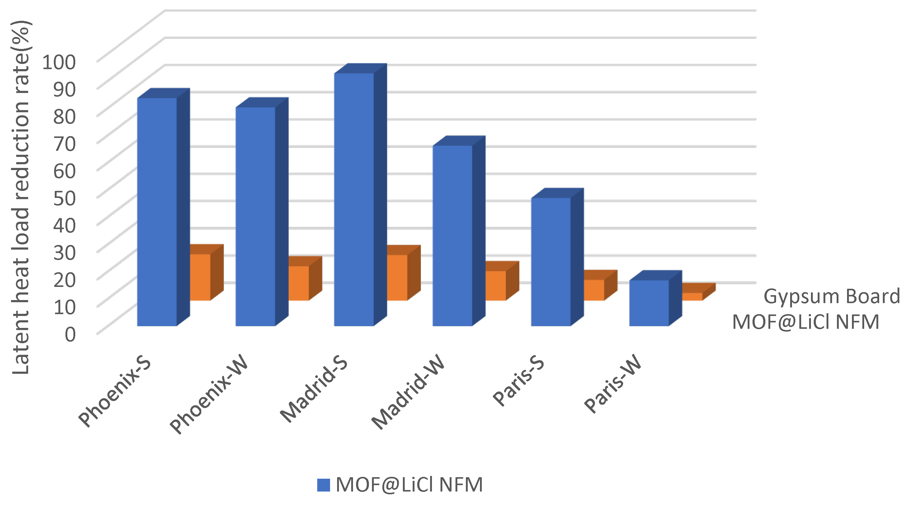
| Phoenix | Latent Load (kWh) | Latent Load Reduction Rate | ||
|---|---|---|---|---|
| Summer | Whole Year | Summer | Whole Year | |
| Cases without moisture buffering material | 27.23 | 37.44 | - | - |
| Cases with MOF@LiCl NFM | 4.44 | 7.38 | 83.7% | 80.3% |
| Cases with gypsum board | 22.59 | 32.72 | 17% | 12.6% |
| Madrid | Latent Load (kWh) | Latent Load Reduction Rate | ||
|---|---|---|---|---|
| Summer | Whole Year | Summer | Whole Year | |
| Cases without moisture buffering material | 13.17 | 39.53 | - | - |
| Cases with MOF@LiCl NFM | 0.95 | 13.36 | 92.8% | 66.2% |
| Cases with gypsum board | 10.97 | 35.26 | 16.7% | 10.8% |
| Paris | Latent Load (kWh) | Latent Load Reduction Rate | ||
|---|---|---|---|---|
| Summer | Whole Year | Summer | Whole Year | |
| Cases without moisture buffering material | 25.33 | 76.03 | - | - |
| Cases with MOF@LiCl NFM | 13.42 | 63.26 | 47.1% | 16.8% |
| Cases with gypsum board | 23.41 | 73.87 | 7.6% | 2.8% |
Disclaimer/Publisher’s Note: The statements, opinions and data contained in all publications are solely those of the individual author(s) and contributor(s) and not of MDPI and/or the editor(s). MDPI and/or the editor(s) disclaim responsibility for any injury to people or property resulting from any ideas, methods, instructions or products referred to in the content. |
© 2023 by the authors. Licensee MDPI, Basel, Switzerland. This article is an open access article distributed under the terms and conditions of the Creative Commons Attribution (CC BY) license (https://creativecommons.org/licenses/by/4.0/).
Share and Cite
Ding, D.; Qin, M. Metal–Organic Frameworks (MOFs) Based Electrospun Nanofiber Membrane for Passive Indoor Moisture Control. Buildings 2023, 13, 1192. https://doi.org/10.3390/buildings13051192
Ding D, Qin M. Metal–Organic Frameworks (MOFs) Based Electrospun Nanofiber Membrane for Passive Indoor Moisture Control. Buildings. 2023; 13(5):1192. https://doi.org/10.3390/buildings13051192
Chicago/Turabian StyleDing, Dong, and Menghao Qin. 2023. "Metal–Organic Frameworks (MOFs) Based Electrospun Nanofiber Membrane for Passive Indoor Moisture Control" Buildings 13, no. 5: 1192. https://doi.org/10.3390/buildings13051192
APA StyleDing, D., & Qin, M. (2023). Metal–Organic Frameworks (MOFs) Based Electrospun Nanofiber Membrane for Passive Indoor Moisture Control. Buildings, 13(5), 1192. https://doi.org/10.3390/buildings13051192