Abstract
In order to improve the force performance of traditional anti-buckling energy dissipation bracing with excessive non-recoverable deformation caused by strong seismic action, this paper presents a prestress-braced frame structure system with shape memory alloy (SMA) and investigates its deformation characteristics under a horizontal load. Firstly, this paper establishes a theoretical analysis model by analyzing the geometric relationship between the deformation of SMA cables and inter-story displacement based on the internal force balance equation. The model is used to solve the anti-lateral displacement stiffness of the SMA cable-supported frame structure and to derive a reasonable formula for calculating the initial prestress and cross-sectional area of SMA cables. Then, the mechanical behavior of the SMA cable-supported frame structure system under an equivalent horizontal load is simulated using ABAQUS software and compared with the calculated results of conventional tie-supported and non-dissipative-supported frame structures. The results show that the force performance of the frame structure system determined by the SMA cable design method proposed in this paper is significantly improved under the horizontal load. Furthermore, it can ensure a certain ductility requirement of the frame structure system, which verifies the effectiveness of the design method of the SMA cable frame structure system proposed in this paper.
1. Introduction
In recent years, prefabricated concrete structures have been rapidly developed in China, and the poor seismic performance of these structures is a major issue. The addition of energy-dissipative bracing in the structure can both provide higher lateral movement resistance stiffness to the structural system and consume energy during an earthquake [1]. Scholars both at home and abroad are currently investigating the use of buckling-resistant energy-dissipative bracing in prefabricated structures [2,3].
The development and application of a buckling-restrained brace (BRB) provide a new direction for prefabricated concrete structures, but there are limitations to traditional BRB structures in seismic applications of concrete structures [4], which are mainly reflected in the following two aspects. First, after a strong earthquake, the non-recoverable deformation of BRBs is substantial, and the structural stiffness and strength are degraded to a certain extent, while the available seismic monitoring data show that strong earthquakes are often accompanied by strong aftershocks. When the structure is subjected to strong aftershocks, the damage worsens, and the structure can even collapse. BRBs often sustain unrecoverable deformation under strong earthquakes, which leads to the cumulative residual deformation of the structure and reduced lateral stiffness. The post-earthquake function of the structures cannot be guaranteed, and the repair costs are high. A large number of scholars have carried out research on self-centering (SC) structures in response to the seismic functional requirements of structures after strong earthquakes. For example, Longhe Xu [5] investigated the design method of self-centering braces; Li [6] proposed a self-centering precast concrete frame system with hysteresis dampers; and Jeffrey Erochkop [7] conducted shake table tests on three-story self-centering-braced frames and proposed a design method. As a new intelligent alloy material, shape memory alloys (SMAs) have the advantages of a superelasticity effect, a shape memory effect, high damping, and high durability. In recent years, damping devices, supporting components, and connecting devices made of SMAs have been used in resilient structures [4,8,9,10,11,12,13]. SMAs can alternatively be SC members, especially when the deformation demand is high. Using SMAs in critical members such as beam-to-column connections and braces has become an emerging strategy promoting structural SC capability. However, performance degradation, heat treatment, strain rate effects, and sensitivity to temperature need to be fully considered when using SMAs [14,15].
Prestressed cables can improve structural forces considerably by adjusting the cable force according to the seismic demand of the structure and then changing the lateral stiffness of the structure with a simple and promising design [16,17]. This paper presents the application of prestressed SMA cables to the prefabricated frame structure system, which makes full use of the advantages of the high strength and stiffness of cable bracing, as well as improving on the inconvenient application of traditional cable with its low ductility to the frame structure where high lateral displacement may occur. The seismic performance of the braced system depends on the initial prestress value and cross-sectional area of the SMA cables [17,18]. In this paper, the equilibrium equation is established on the basis of the frame structure system after deformation, and the calculation method of the initial prestress, and the cross-sectional area of the cables in the SMA cable-supported prefabricated frame structure system is derived.
2. Material Properties and Constitutive Relations of SMAs
2.1. Shape Memory Effect and Superelasticity of SMAs
SMAs have three material properties. First, due to the shape memory effect (SME), SMAs deform after being subjected to a load. After heating, the deformation of the material will disappear, and it will return to its initial state, with no residual deformation occurring [19]. Second, superelasticity (SE) involves stretching SMAs to produce deformation beyond the elastic limit and the ability to recover the initial state after unloading. Third, when SMAs are in the state of both martensite and austenite, the material damping is at its maximum, which makes the damping performance of SMA material superior to that of other metal materials. Among the various types of shape memory alloys, the most successful is the superelastic NiTi SMA, which has a recoverable strain of up to 10% with moderate energy dissipation when cyclically loaded at room temperature [14].
2.2. The Constitutive Relations of SMAs
The crystal structure of SMA usually has two forms: when the material temperature is high, its crystal shows a cubic structure with high hardness, called the austenite phase (A), while at low temperatures, the crystals show a low-symmetric monoclinic structure with low hardness, called the martensitic phase (M). When the crystal transforms from the austenite phase to the martensite phase, it is called a positive martensite phase change; when the material crystal transforms from the martensite phase to the austenite phase, it is called a reverse martensite phase change. The change in crystal state is related to the temperature and the change in stress to which the material is subjected, and the different causes of the induced crystal changes give SMAs their unique and diverse mechanical properties. Specifically, when SMAs are stressed at a temperature below the martensite finish temperature Mf, SME occurs. After unloading, a residual strain develops, but this permanent strain can be completely recovered when the temperature rises above the austenite finish temperature Af (the temperature at the end of reverse martensitic transformation). Furthermore, when an SMA is strained at a temperature higher than Af, and the produced strain is recoverable immediately after unloading, SE is shown [20].
In 1970, Muller, a foreign scholar, first proposed a study on the constitutive models of SMAs, and many scholars have proposed different constitutive models in subsequent studies. The current constitutive models of SMAs are broadly classified into four categories [21]: single-crystal theory models, mathematical models, fine-scale mechanical models, and image-only theory models. The mathematical expressions of these four models and the theories they are based on are different, and each constitutive model has its limitations under specific conditions, but all four constitutive models have their applicability depending on the research content. This paper adopts the phenomenological theory constitutive model, as shown in Figure 1. The model is based on the principles of thermodynamics and is characterized by plasticity theory, which is suitable for solving problems related to engineering applications. Among them, the Brinson [22] constitutive model developed on the basis of the Liang model is the most representative, and its expression is shown in Equation (1):
where T, ɛ, and σ denote temperature, strain, and stress, respectively; T0, ɛ0, and σ0 represent their corresponding initial values; D is the material modulus of elasticity; ξS and ξT refer to the stress-induced and temperature-induced martensitic phase percentages, respectively; ξS0 and ξT0 depict their corresponding initial quantities; ΩT and ΩS are the phase change tensors corresponding to ξS and ξT; and Θ is the thermoelastic modulus.
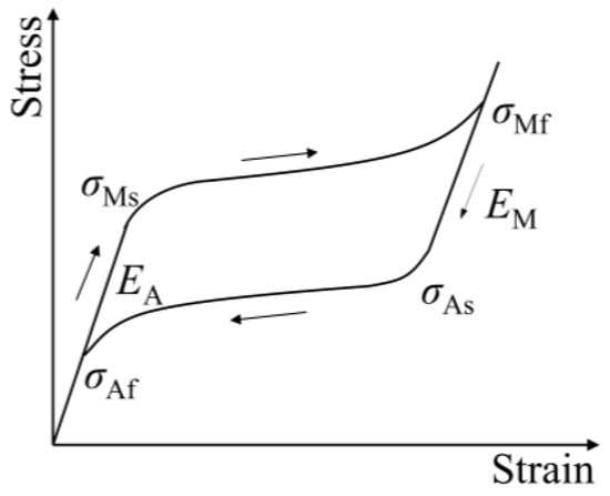
Figure 1.
Principal structure relationship diagram of shape memory alloy: the arrows indicate the direction of martensitic transformation.
3. Method for Determining the Initial Prestress of SMA Cables
3.1. Relationship between Deformation of SMA Cables and Interlayer Displacement of Structure
Based on the mass and stiffness distribution characteristics of a concrete frame structure, the following assumptions need to be made when analyzing the passive control system of SMA cables subjected to horizontal loads: first, consider the rigid floor assumption, which in this paper assumes infinite floor stiffness, the same floor elevation at the same horizontal displacement, and ignores column axial deformations; second, due to the particularity of SMAs, the influence of cable sag on the elastic modulus of cable is ignored; third, assume that T is constant and T > Af (the temperature at the end of reverse martensitic transformation) while the cable is in use, disregarding the temperature change in the SMA cables; fourth, the fatigue damage of SMA cables due to cyclic loading is neglected; and fifth, assuming small displacements of the frame structure, the derivation of the equations in this paper is carried out.
The cables are connected to the frame structure with prefabricated gusset plates. Beams, columns, and nodal plates are fabricated at the factory and assembled at the construction site. The SMA cables are installed by connecting the connection elements of the cable end to the gusset plates. When the prestress-braced structure system is subjected to horizontal loads, such as earthquakes and horizontal wind loads, the structure will undergo lateral movement. SMA cables in a structure are divided into load-raising cables and unloading cables according to the deformation. When the structure moves sideways under an external load, the SMA cables that continue to elongate after prestressing and tensioning are called load-raising cables. SMA cables that shorten after prestressing due to the sideways movement of the structure are called unloading cables. Figure 2 depicts how the single-span prestress-braced structure system deformed when subjected to a horizontal load.
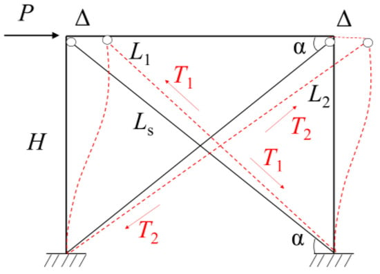
Figure 2.
Deformation of a structural system under horizontal load.
In this figure, H is the height of the structural floor, Ls represents the length of SMA ties after applying prestress, L1 denotes the length of unloaded ties after deformation, L2 refers to the length of load-boosting ties after deformation, Δ represents the inter-story displacement occurring in the structure, α is the angle between SMA ties and horizontal ground before the structure is loaded, and T1 and T2 indicate the force directions of the unloaded ties and load-boosting ties, respectively.
According to the geometric relationship among the members in the schematic diagram of structural deformation in Figure 2, and then using the cosine theorem, the relationship between the compression of the unloaded cable and the tension of the loaded cable, and the displacement between the layers can be expressed as follows.
The compression of the unloading cable (l1) is calculated according to the following formula in Equation (2):
The tensile amount (l2) of the load-extending cable is calculated according to the following formula in Equation (3):
Ls in Equations (2) and (3) refer to the length of SMA cables after prestress application, as shown in Equation (4):
3.2. Relationship between the Initial Prestress of SMA Cables and the Initial Deformation of the Cables
The relationship between the initial prestress, and the initial deformation of common metal ties has been investigated [23]. In this paper, the relationship between the initial prestress of SMA cables and the initial deformation of the cables will be investigated using the superelasticity of SMAs. The majority of SMA constitutive models have a complicated equation structure, include a large number of physical factors, are highly nonlinear, and are computationally inefficient. Using the experimental results of NiTi shape memory alloy wires and the martensitic transformation kinetic equations of Brison’s model, Xin Chen found the relationship between transformation stress and loading conditions. By means of a linear method, a superelastic simplified one-dimensional constitutive model of SMA was established [24]. In this paper, the superelasticity of SMAs is studied using this simplified model, as shown in Figure 3. In the figure, point A is the start of the martensitic phase transformation, σms represents the start stress of martensitic phase transformation, and ɛms denotes the start strain of martensitic phase transformation. Point B is the end point of martensitic phase transformation, which is also the maximum recoverable deformation point. σmf represents the end stress of martensitic phase transformation, ɛmf stands for the strain at the end of martensitic phase transformation, k1 represents the slope of the OA section (the elastic section), and k2 denotes the slope of the AB section (the inelastic section).
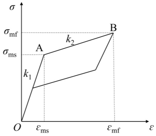
Figure 3.
Simplified hyperelastic stress–strain relationship of SMAs.
According to Figure 3, the modulus of elasticity E1 in the elastic phase (OA) and the modulus of elasticity E2 in the inelastic phase (AB) of SMA materials are calculated according to the following formulas in Equations (5) and (6):
Equation (7) can be used to express the stress in SMA cables during the martensitic phase transition:
Figure 4 shows the deformation of SMA ties in the elastic phase (OA) under axial external load. L is the length of the ties when they are not tensioned; Ls denotes the length of the ties after initial tensioning; and lc1 represents the elongation of the ties after tensioning. The relationship between the initial prestress of the cables, and the initial elongation of the cables can be derived from the geometric relationship in Figure 3 and the material properties of the cables. σ is the initial prestress in Equation (8):
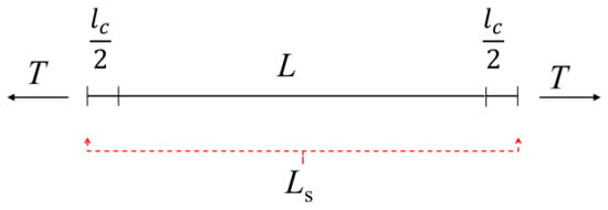
Figure 4.
Axial tensile deformation of SMA cable.
In this paper, the structure is analyzed according to the initial prestress value of SMA cables when they are in the inelastic stage of material (AB). When the SMA cables apply the initial prestress value in the AB section, the SMA has undergone martensitic phase transformation and entered the inelastic phase, and the relationship between the initial prestress (σ) and the cable elongation (lc2) at this stage of the SMA cables can be expressed according to Equation (9):
where is the elongation of the cable when the prestress is taken as σms at point A. From this, the relationship between the initial prestress (σ) and the initial elongation (lc) of the SMA cables can be derived, as shown in Equation (10):
3.3. The Formula for the Value of the Initial Prestress of the Unloading Cable
The SMA cables in the prefabricated concrete frame prestressed structure are arranged crosswise at the structural beam-column nodes. When the structure is subjected to the horizontal load shown in Figure 2, the prestressed SMA cable on one side continues to increase the load due to the lateral displacement of the structure, while prestressed SMA cable on the other side unloads.
In order to reduce or suppress inter-story displacement when the structure is subjected to concentrated lateral load, all cables should be in a state of tensile stress in the initial state and during the working process, and the initial prestress of SMA cables on the same floor should be as close as possible. This can be well realized by taking advantage of the large recoverable strain of SMAs. Prestress the SMA cables so that the initial tensile strain is close to half of the maximum strain that can be recovered during the phase change of the shape memory alloys, which can absorb and dissipate the energy generated by external loads by utilizing the superelastic properties of SMAs, while also ensuring that the SMA cables are always in tensile stress without compressive stress during operation [25].
It is clear from this that the SMA prestressed unloading cable only functions if the unloading cable’s compression is always smaller than the SMA prestressed cable’s initial elongation under the design horizontal external load, as shown in Equation (11):
Substituting Equations (2) and (10) into Equation (11), the relationship between the initial prestress of the unloaded cable and the interlayer displacement can be obtained, as shown in Equation (12):
Equation (12) provides the lower limit value of the initial prestress of SMA cables, and it can be seen that when SMA material properties and cable arrangements are taken into consideration, the initial prestress of the ties is determined by the interlayer displacement, independent of the cross-sectional area of the cables.
3.4. Equation for the Value of the Initial Prestress of the Load-Boosting Cable
The load-boosting cables will continue to be stretched, and the stress on the SMA cables will continue to rise until they are torn out when the prefabricated prestressed concrete frame structure is subjected to horizontally focused pressures. The lower limit of the first prestress has been determined. However, if the prestress value is taken too high, the structure will be laterally moved, and the load-boosting cable is likely to be severed. Therefore, based on the force condition of the SMA load-bearing cable, it is important to estimate the upper limit value of the first prestress.
According to the material properties of SMAs, under a horizontal external load on the structure, the stress change of the load-bearing cable cannot exceed the maximum recoverable stress of SMAs. The geometric relationship is expressed as follows: under the external design load, the sum of the elongation l2 of the load-boosting cable and the initial prestressing elongation lc shall be less than the ultimate elongation lu of the SMA cable, as shown in Equation (13).
From Figure 2, it can be seen that the ultimate elongation of SMA cables can be expressed by σmf and ɛmf, as shown in Equation (14):
Substituting Equations (3), (10), and (14) into Equation (13), the relationship between the initial prestress force of the load-boosting cable and the interlayer displacement can be obtained, as shown in Equation (15):
From Equation (15), it can be seen that the upper limit of an SMA cable’s prestress is related to the structural interlayer displacement when the SMA material properties and structural geometric parameters are determined.
3.5. The Formula for the Initial Prestress of SMA Cables
The SMA cable-supported prefabricated frame structure system is subjected to concentrated horizontal load, in which the definition of the load-boosting and unloading cables may be transformed due to the uncertainty of the load direction. When the direction of the external load changes, the original load-boosting cable may change to the unloaded state, and the unloaded cable may change to the continued tension state. As a result, the design of SMA cable prestressing should satisfy the value guidelines for both the load-boosting and the unloading cables. Combined with the previous guidelines regarding the values of the prestress equations for the load-adding and unloading cables, the range of values for the initial prestress of SMA cables is further narrowed, as shown in Equation (16):
Equation (16) is the formula for the value of the initial prestress of SMA cables for the SMA cables-supported frame structure system, which is derived theoretically and gives the upper and lower limit values of the prestress value, providing a systematic calculation process for the SMA prestress value method, as well as engineering design guidance.
4. Lateral Stiffness Calculation of SMA Cable-Supported Prefabricated Frame Structure System
The lateral stiffness of the SMA cable-supported prefabricated frame structure system is calculated based on the force equilibrium equation of the structure under external load. The basic assumptions in Section 2.1 are adopted, and the calculation sketch is shown in Figure 5.
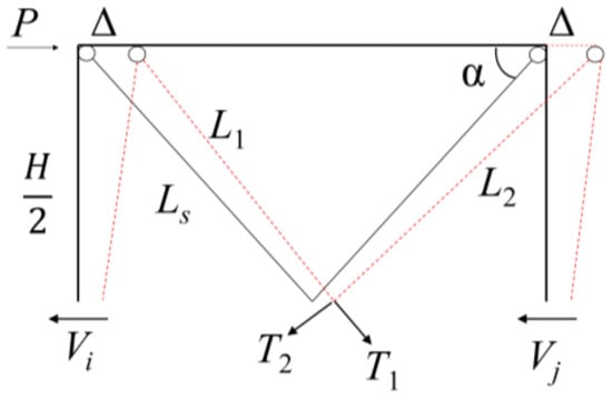
Figure 5.
Structural force diagram under horizontal load.
In Figure 4, the length of the column is represented by H/2, Vi is the shear force on the i-th column, Vj is the shear force on the j-th column, T1 stands for the tension value of the unloaded cable under the horizontal load, and T2 refers to the tension value of the loaded cable under the horizontal load.
According to the hyperelastic stress–strain relationship of SMAs, the initial pretension value of SMA cables is calculated as shown in Equation (17). In the equation, A is the SMA cable cross-sectional area, and ɛ represents the SMA cable strain:
Under the concentrated horizontal load, the structure shifts sideways, the tension of the unloaded cable becomes T1, and the tension of the loaded cable becomes T2. In the following equation, TΔ1 is the value of the tensile force lost by the unloaded cable under a concentrated horizontal load, and TΔ2 represents the value of the tensile force increased by the loaded cable under a concentrated horizontal load, as shown in Equations (18) and (19):
The deformation of the SMA cable-supported prefabricated frame structure system under the action of the concentrated horizontal force is less, as is the change in angle between the SMA prestressed cable and the horizontal plane after lateral shift. Therefore, ignoring the amount of change in the angle between the SMA prestressed cables and the horizontal plane, the angle remains α after the deformation of the structure. According to this assumption, the equilibrium equation in the horizontal direction after the force on the structure can be obtained as Equation (20):
According to the assumptions in Section 2.1, using the calculation method of the displacement method solution in structural mechanics, we can derive Equation (21). In the formula, ici represents the linear stiffness of the i-th column, icj is the linear stiffness of the j-th column, and Δ denotes the inter-story displacement occurring in the structure, as shown in Equation (21):
From the geometric relationship of the structure and Hooke’s law, we can obtain Equation (22). Substituting Equations (21) and (22) into the structural equilibrium equation, we can derive Equation (23):
In order to find the lateral stiffness of the SMA tie-supported prefabricated frame system, it is necessary to use the method of defining the structural stiffness. The stiffness is the force required to cause a unit displacement. Therefore, taking the lateral shift value Δ occurring in the structure as 1, the external force applied is the lateral stiffness resistance of the SMA cable-supported prefabricated frame structure system, as shown in Equation (24):
From Equation (24), it can be seen that the lateral stiffness of the SMA cable-supported prefabricated frame structure system is related to the geometric parameters of the structural members, the material properties, the material properties of the SMA cables, the section size, and the angle between the SMA cables and the horizontal plane, independent of the initial prestress value of the SMA cables and independent of the inter-story displacement of the structure.
5. Design Method of Initial Prestressing and Cross-Sectional Area of SMA Cable-Supported Prefabricated Frame Structure System Cables
Equation (16) is the formula for the range of initial prestressing values for the SMA cable-supported prefabricated frame structure system. When the material properties and the geometric length of the SMA, and the angle between the cable and the horizontal plane are known, the formula can be used to obtain a range of values for the initial prestress of the SMA cables. At the same time, it solves the problem of the unloading cable not being completely unloaded, and the load-boosting cable tension is in the safe range when the SMA cables are working.
Based on Equations (16) and (24), this paper presents a method for determining the initial prestressing force and the cross-sectional area of the cables in the SMA cable-supported prefabricated frame structure system. Firstly, the lateral stiffness of each floor of the pure frame structure is calculated, and the inter-story displacement value of each floor is preset within the range of inter-story displacement taken to meet the seismic requirements in accordance with the Code for Seismic Design of Buildings [26]. The cross-sectional area of the SMA cables for each floor is then calculated in accordance with Equation (23) under the external design load. Next, an initial prestress value is assumed based on the cross-sectional area of the SMA cables, and the actual deformation of the structure under the external design load is calculated to determine if the stress after the deformation of the cables is zero and if it is, the initial prestress is reset until the stress of the SMA cables after deformation is greater than zero. Finally, a check is conducted on whether the interlayer displacement value meets the requirements, and the interlayer displacement value is substituted into Equation (16) to obtain the range of initial prestressing values for the SMA cables. The final initial prestress value of the SMA cables is then selected from this range of values. The design flow chart is shown in Figure 6.
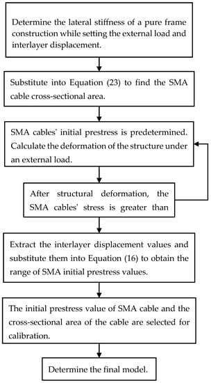
Figure 6.
Flow chart of model parameter design.
6. Example
In this paper, based on the model proposed in the literature [27], a two-story, single-span SMA prestress-braced prefabricated concrete frame structure is described with a height of 3.6 m at the first story, a height of 3.3 m at the second story, and a span of 6 m. The SMA cables are arranged in the form of crosses, as shown in Figure 7. The cross-sectional size of the beam is 300 mm by 600 mm, the cross-sectional size of the column is 400 mm by 400 mm, the standard value of the permanent load on the floor and the roof is taken as 4 kN/m2, the standard value of the live load is taken as 2 kN/m2, and the load on the wall above the beam is taken as 5.5 kN/m. The strength grade of the concrete is C35, the protective layer thickness of the beam and the column is 25 mm, the type of longitudinal reinforcement is HRB400, and the type of hoop reinforcement is HPB300.
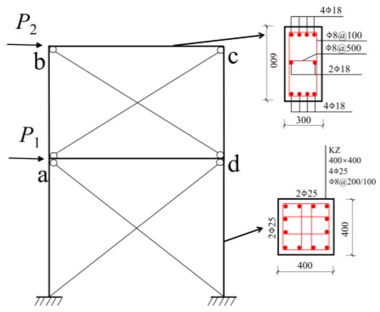
Figure 7.
Sketch of model calculation.
ABAQUS software is used for the nonlinear analysis of this example. The beams and columns are modeled with solid elements, and the steel bar and SMA cables are modeled with wire elements, with the required parameters for defining the SMA shown in Table 1 [28]. Two steel gaskets are arranged on one side of the column to prevent stress concentration caused by the load. In ABAQUS, TIE is selected in the interaction module to connect the SMA cables to the frame structure. The finite element model is shown in Figure 8. The prestress is applied to the SMA cables using the cooling method, and the nonlinear deformation of the structure is considered in the analysis step. The load application process is as follows: firstly, the initial prestress is applied to the SMA cables, the gravity load is then applied to the frame structure, and finally, the horizontal load is applied at the beam-column nodes to observe the inter-story displacement and the change in cables stress in the structure. The calculation model of this example is divided into three groups: K-1 (the pure frame structure), K-2 (the SMA cable-supported frame structure with 0 prestress), and K-3 (the SMA cable prestress-supported frame structure).

Table 1.
Ontogenetic parameters of SMA.
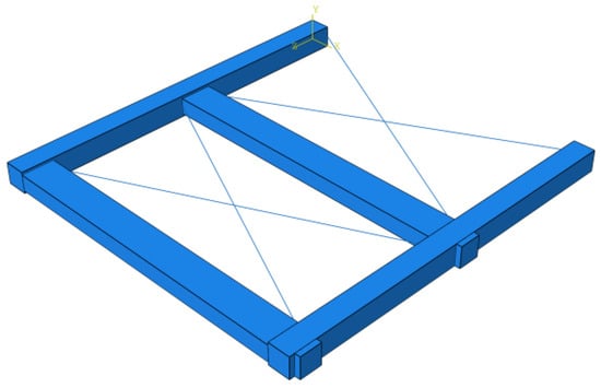
Figure 8.
The finite element model.
The model is analyzed using the quasi-static method. The dynamic loads generated by the earthquake are loaded onto the structure in the form of static forces. The design process for determining the initial pretension of prestressing ties is as follows. First, the lateral stiffness of the designed pure frame structure is determined, and the horizontal load value is calculated based on the internal force and lateral shift of the structure as a result of encountering multiple earthquakes. The horizontal load of the first layer is 7.4 kN, the horizontal load of the second layer is 13.77 kN, and then, according to the preset inter-story displacement value, these data are substituted into Equation (23), with the diameter of the ties taken to be 8 mm, and the cross-sectional area as 50.26 mm2. Using data calculated by the formula, the tension cable cross-sectional area and prestress are applied to the structure to obtain the structural deformation results, which are compared with the pure frame structure calculation results, shown in Table 2.

Table 2.
Lateral shift values of the structure (mm).
Due to the superelasticity of SMA, there is a nonlinear relationship between the stress and strain of the material, and the prestress applied to the cable is in the inelastic phase of the material. When the concrete frame structure is subjected to the load, the deformation produced is small, so the stress change in the tension cable is small and still in the inelastic phase. From Table 2, it can be seen that the lateral displacement of the structure is small because the lateral concentration force is small. The setting of SMA prestressed cables can effectively improve the lateral stiffness of the frame structure and reduce the inter-story displacement of the structure. Compared with the K-1 model, the maximum inter-story displacement of the first layer of the K-3 model is reduced by 98.05%, and the maximum inter-story displacement of the second layer is reduced by 98.53%. The tensile force values of the ties after deformation are also greater than zero and have a high safety reserve, which verifies the validity of the formula calculation results.
Comparing the K-2 model, because the SMA cables in the K-3 model are set with initial prestressing, it results in a larger lateral shift at points a and b of the structure than the lateral shift at the corresponding positions in the K-2 model. However, compared with the K-2 model, the lateral displacement value at c in the K-3 model is reduced by 57.57%, and the lateral displacement value at d is reduced by 35.34%. Therefore, from the perspective of the overall structural deformation, the application of prestress is effective in reducing the lateral displacement of the structure.
To investigate the working performance of SMA prestressed cables in-depth, the effect of SMA cables on the lateral displacement value of the frame structure when the structure is subjected to different lateral concentrated forces is investigated, assuming that the beam-column members are all in the elastic phase. The initial prestress of SMA ties is still 15 kN, and the cross-sectional area is 50.26 mm2. The first and second floors of the structure are subjected to the same forces, and the concentrated lateral forces are set to 10 kN, 20 kN, 40 kN, 80 kN, and 160 kN for five working conditions. The lateral displacement values of the structure are observed and compared with the calculated results of the pure frame structure, with the results shown in Figure 9. In addition, the deformation diagrams of the structures are shown in Figure 10.
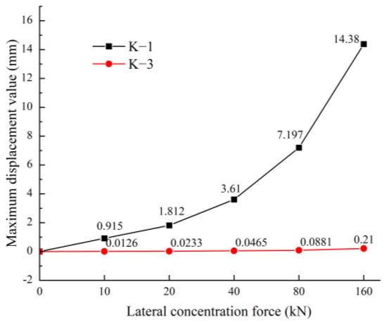
Figure 9.
Comparison of the maximum displacement value of the structure.
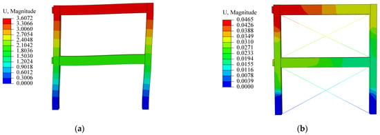
Figure 10.
Under the load of 40 kN: (a) deformation diagram of K-1; (b) deformation diagram of K-3.
From Figure 9, it can be seen that, with the increase in concentrated lateral force, the lateral displacement of the K-1 structure and the K-3 structure becomes larger, and the lateral displacement of the frame structure with SMA prestressed cables is significantly smaller compared with the pure frame structure. This indicates that SMA prestressed cables increase the lateral displacement resistance stiffness of the structure and absorb most of the energy when the structure is deformed by forces, resulting in smaller displacements of the frame structure. Simultaneously, due to the structure’s small displacement, the stress change in SMA cables is small, resulting in SMA cables that are always in tension with a high safety reserve.
7. Summary and Conclusions
In this paper, SMA cables were applied to a prefabricated concrete frame structure system. The initial prestressing range of SMA cables and the method of calculating the cross-sectional area of the ties were derived using the principal structure relationship of SMA and the deformation of the frame structure when subjected to concentrated lateral forces. The following conclusions were drawn:
- (1)
- The range of values of the initial prestress of the SMA cables, as determined by the material properties and cable arrangement, is related to the inter-story displacement of the structure and is not related to the cross-sectional area of the cable.
- (2)
- The lateral stiffness of the structure is only related to the geometric parameters of the structural members, material properties, material properties of the SMA cables, section size, and angle between the SMA cables and the horizontal plane and is not related to the initial prestressing of the SMA cables.
- (3)
- The feasibility of the design method proposed in this paper was verified by the calculation example, ensuring that the SMA cables are always in tension during operation. By applying SMA cables to the prefabricated concrete frame structure, the lateral stiffness of the frame structure is improved, and the deformation of the structure, when subjected to concentrated lateral forces, is reduced.
In the project, the designer should pay special attention to the connection of the SMA cables to the frame structure to ensure that the cables do not fall off accidentally during the work. At the same time, the designer needs to control the temperature of the SMA cables so that the material’s superelasticity can be fully utilized. The work carried out in this paper is insufficient, and in the subsequent research, many other aspects should also be considered, such as the effect of residual displacement on the structure and whether there will be stress concentrations generated at the connection between the concrete structure and the cables. The deformation of the structure studied in this paper is small, but whether SMA ties can still work effectively when the structure is subjected to rare earthquakes and mainshock-aftershock sequences needs to be studied more thoroughly.
Author Contributions
Conceptualization, X.Z.; supervision, X.Z. and Q.Y.; writing—original draft, Q.Y.; data curation, Q.Y. and J.C.; writing—review and editing, X.Z. and L.C.; software, Q.Y., T.D. and Y.H.; methodology, Q.Y.; investigation, A.L. All authors have read and agreed to the published version of the manuscript.
Funding
This work is partially supported by the National Natural Science Foundation of China (Grant No. 51978543), Graduate Innovative Fund of Wuhan Institute of Technology (Grant No. CX2022205).
Data Availability Statement
The data presented in this study are available on request from the corresponding author.
Conflicts of Interest
The authors declare no conflict of interest.
References
- Qiu, C.; Jiang, T.; Liu, J.; Du, X. Self-Centering Knee-Braced Steel Frames with Buckling-Restrained NiTi SMA BARS: Component Test and Structural Behavior. Eng. Mech. 2022, 39, 1–14. [Google Scholar]
- Liu, X.; Zhang, A.; Ma, J.; Tan, Y.; Bai, Y. Design and Model Test of a Modularized Prefabricated Steel Frame Structure with Inclined Braces. Adv. Mater. Sci. Eng. 2015, 2015, 291481. [Google Scholar] [CrossRef]
- Yin, H.; Shi, G. Finite element analysis on the seismic behavior of fully prefabricated steel frames. Eng. Struct. 2018, 173, 28–51. [Google Scholar] [CrossRef]
- Qiu, C.; Du, X. A state-of-the-art review on the research and application of self-centering structures. Chin. Civ. Eng. J. 2021, 54, 11–26. [Google Scholar]
- Xu, L.; Jing, Q.; Xie, X. Performance study on RC frame structures with self-centering braces under main-and after-earthquakes. Eng. Mech. 2022, 39, 1–8. [Google Scholar]
- Li, Y.; Ding, Y.; Geng, F.; Wang, L. Seismic response of self-centering precast concrete frames with hysteretic dampers. Struct. Des. Tall Spec. Build. 2019, 28, e1604. [Google Scholar] [CrossRef]
- Erochko, J.; Christopoulos, C.; Tremblay, R.; Kim, H. Shake table testing and numerical simulation of a self-centering energy dissipative braced frame. Earthq. Eng. Struct. Dyn. 2013, 42, 1617–1635. [Google Scholar] [CrossRef]
- Dolce, M.; Cardone, D. Theoretical and Experimental Studies for the Application of Shape Memory Alloys in Civil Engineering. J. Eng. Mater. Technol. 2006, 128, 302–311. [Google Scholar] [CrossRef]
- Song, G.; Ma, N.; Li, H.N. Applications of shape memory alloys in civil structures. Eng. Struct. 2006, 28, 1266–1274. [Google Scholar] [CrossRef]
- Kim, Y.C.; Shahriyer, H.; Hu, J.W. Study on numerical seismic performance evaluation of 3D building frame with smart self-centering BRBs system. Case Stud. Constr. Mater. 2022, 17, e01666. [Google Scholar] [CrossRef]
- You, T.; Wang, W.; Tesfamariam, S. Effects of self-centering structural systems on regional seismic resilience. Eng. Struct. 2023, 274, 115125. [Google Scholar] [CrossRef]
- Shu, G.; Li, R. Experimental study on seismic performance of pin-connected steel frame-self-centering-energy-dissipation bracing substructure. J. Southeast. Univ. Nat. Sci. Ed. 2021, 51, 187–194. [Google Scholar]
- Huang, H.; Zhang, W. Research overview of different families of shape memory alloys used in structure vibration control. J. Vib. Shock. 2019, 38, 154–164. [Google Scholar]
- Fang, C.; Qiu, C.; Wang, W.; Alam, M.S. Self-Centering Structures Against Earthquakes: A Critical Review. J. Earthq. Eng. 2023. [Google Scholar] [CrossRef]
- Fang, C. SMAs for infrastructures in seismic zones: A critical review of latest trends and future needs. J. Earthq. Eng. 2022, 57, 104918. [Google Scholar] [CrossRef]
- Lee, J.-H.; Oh, S.-G.; Hisham, E.-G. 3-D Configuration Effects of Prestressing Cable Bracing Used for Retrofitting a RC Frame Subjected to Seismic Damage. J. Korea Inst. Struct. Maint. Insp. 2003, 7, 183–191. [Google Scholar]
- Zhang, A.; Zhao, L.; Liu, X.; Sun, Y. Design Method of Cable Sectional Area of Prestress-braced Steel Frame Structure. Int. J. Space Struct. 2015, 41, 381–387. [Google Scholar]
- Fanaie, N.; Aghajani, S.; Dizaj, E.A. Theoretical assessment of the behavior of cable bracing system with central steel cylinder. Adv. Struct. Eng. 2016, 19, 463–472. [Google Scholar] [CrossRef]
- Liu, H.; Xu, Z. Seismic Response Analysis for Frame-structures Based on SMA Tendons. Earthq. Resist. Eng. Ret. 2006, 28, 76–79. [Google Scholar]
- Fang, C.; Zheng, Y.; Chen, J.; Yam, M.; Wang, W. Superelastic NiTi SMA cables: Thermal-mechanical behavior, hysteretic modelling and seismic application. Eng. Struct. 2019, 183, 533–549. [Google Scholar] [CrossRef]
- Zhou, B. A macroscopic constitutive model of shape memory alloy considering plasticity. Mech. Mater. 2012, 48, 71–81. [Google Scholar] [CrossRef]
- Brinson, L. One-dimensional constitutive behavior of SMA: Thermomechanical derivation with non-constant material functions and redefined. J. Intell. Mater. Syst. Struct. 1993, 4, 167–175. [Google Scholar] [CrossRef]
- Zhang, A.; Zhao, L.; Liu, X.; Sun, Y. Design Method of Initial Tension of Cables in Prestress-braced Steel Frame Structure. J. Beijing Univ. Technol. 2014, 40, 1804–1809. [Google Scholar]
- Chen, X.; Li, A.; Zuo, X. Simplified Multidimensional Constitutive Model of super-elasticity shape memory alloy. J. Southeast. Univ. Nat. Sci. Ed. 2009, 39, 813–818. [Google Scholar]
- Wang, D.; Su, S.; Shen, Y. Analysis of seismic response of passively controlled structures with shape memory alloy cables. Chin. Civ. Eng. J. 2000, 33, 56–62. [Google Scholar]
- Elghazouli, A. Code for Seismic Design of Buildings, 2016 ed.; China Architecture & Building Press: Beijing, China, 2016; pp. 355–361. [Google Scholar]
- Du, C. Analysis of Seismic Resilient Deformation Performances of SMA-Concrete Structures; Shenyang Jianzhu University: Shenyang, China, 2020. [Google Scholar]
- Yang, Z. Development of Constitutive Model and Seismic Reduction Effect of Shape Memory Alloy; Institute of Engineering Mechanics, CEA: Harbin, China, 2021. [Google Scholar]
Disclaimer/Publisher’s Note: The statements, opinions and data contained in all publications are solely those of the individual author(s) and contributor(s) and not of MDPI and/or the editor(s). MDPI and/or the editor(s) disclaim responsibility for any injury to people or property resulting from any ideas, methods, instructions or products referred to in the content. |
© 2023 by the authors. Licensee MDPI, Basel, Switzerland. This article is an open access article distributed under the terms and conditions of the Creative Commons Attribution (CC BY) license (https://creativecommons.org/licenses/by/4.0/).