Article

Reuse of Abandoned Shield Residues Stabilized by a Sustainable Binder: Assessment of Strength, Durability, and Environmental Properties

1
China Railway First Survey and Design Institute Group Co., Ltd., Xi’an 710043, China
2
Shaanxi Provincial Key Laboratory of Railway and Underground Transportation Engineering (China Railway First Institute), Xi’an 710043, China
3
Chongqing Rail Transit (Group) Co., Ltd., Chongqing 401120, China
4
State Key Laboratory of Geohazard Prevention and Geoenvironment Protection, Chengdu University of Technology, Chengdu 610059, China
5
Jiangsu Key Laboratory of Urban Underground Engineering & Environmental Safety, Institute of Geotechnical Engineering, Southeast University, Nanjing 210096, China
6
B-Z Geotechnical Company, Nanjing 210096, China
*
Authors to whom correspondence should be addressed.
Buildings 2023, 13(3), 738; https://doi.org/10.3390/buildings13030738
Submission received: 8 February 2023 / Revised: 4 March 2023 / Accepted: 9 March 2023 / Published: 11 March 2023

Abstract

:
The resourceful reuse, construction, and environmental and safety hazards of shield residues in underground construction have received a lot of attention. This paper reports the assessment of shield residues generated with the underground space development through stabilization. The variations of strength, durability, and environmental properties of magnesium oxide (MgO)-activated ground granulated blast furnace slag (GGBS)-fiber material stabilized shield residues are tested by unconfined compressive strength test, direct shear test, pH test, and modified dry and soaking cycle test (acidic sulfate ion condition, pH = 5.0). Portland cement (PC)-stabilized shield residues are selected as the control group. The optimal ratio of MgO-activated GGBS-fiber-stabilized material is recommended. The test results show that the basalt fiber with 12 mm length and 0.1% ratio is designed as the optimal value. The MgO-activated GGBS-fiber-stabilized shield residues specimens with the ratio of MgO to GGBS of 1:7 display higher unconfined compressive strength (qu) and shear strength (τ). After ten dry–soaking cycles, the qu, τ, and pH of the MgO-activated GGBS-fiber-stabilized shield residues specimens decreased by 21%, 8%, and 12%, respectively, compared to those corresponding to the standard curing time. In contrast, the qu, τ, and pH of the control group were reduced by 46%, 39%, and 13%.

1. Introduction

In recent years, investment in tunnels, municipal pipelines, and other underground structures for transportation, water extraction, and wastewater treatment has grown at a rate of more than 10% per year in China [1,2]. Many cities in China’s urbanization process are competing to develop metro tunnel systems to meet the demands of rapid population growth and accelerated urbanization. As of 2018, more than 100 subway lines with a total length of about 8600 km were under construction or planned in Chinese cities, mainly using shield tunnel boring machines [3]. During shield tunnel construction, a large amount of soil is usually discharged [4]. For example, a subway line usually has two tunnels, each with an excavation diameter of 6 m. The volume of discharged soil and simultaneous grouting material per km is as high as 57,000 m3 and 3000 m3, respectively. Dirt management is receiving more and more attention in the tunnel construction process. The project cost analysis shows that the disposal cost of this waste soil is about RMB 76.96 per cubic meter, which will cause an adverse impact on the surrounding environment during transportation [5]. The amount of synchronized grouting raw materials required during the construction of an earth pressure balance shield tunnel is large, and the disposal of shield residues is costly and polluting to the environment. Past studies show that the shield residues discharged from earth pressure balance shields can replace some of the construction raw materials after simple treatment [6,7].
Material reuse or recycling has two main environmental benefits: (a) reduced waste disposal and (b) reduced raw material extraction. Some recent cases highlight these benefits: (a) the SARMa project [8], including the sustainable production and recycling of aggregates; (b) the DRAGON project [5], analyzing the possibility that tunnel spoil can be used in other industries for the amount of excavated mineral resources; (c) the REMUCK project, to develop innovative approaches for the management of excavated waste recycling [9,10].
The actual resource utilization rate of shield residues of China is less than 1% [1], and the treatment method is still mainly piling and landfill, which has caused a series of construction problems and even secondary environmental and safety hazards, manifested in the following four aspects: (a) Shield residues are prone to spills and dust during transportation, which not only affects urban hygiene, but also reduces surrounding air quality [11,12]. (b) The foam and flocculant in the shield residues migrate with the surface runoff and pollute the surrounding water bodies [13]. (c) The high alkalinity of the shield slag makes it impossible to plant. Sending it to the landfill for burial will take up a lot of land resources and there is still a risk of contaminating groundwater [13]. (d) Generating secondary disasters: the design and operation of the residues dump is not standardized, resulting in the risk of destabilization of the slope of the residues [14,15].
Several factors need to be considered for reusing shield residues, especially the relevant legal regulations. For European countries, the requirements specified in the Waste Framework Directive discussed by Entacher et al. [16] should be met. Despite the calls for waste reduction from all parties involved in the project, the application of these materials is still limited due to a lack of knowledge about their cost, quality, quantity, and applicability. Shield residues from earth pressure balanced shields are usually added to cement for soil improvement [7,17]. In addition, the hydration reaction products can improve the strength of the stabilized shield residues and facilitate recycling waste mud [18,19]. The usual binder used for abandoned soil is Portland cement. Still, low strength and durability restrict the development of Portland cement. In contrast, the process of Portland cement production produces a large amount of atmospheric pollutants, such as CO2, SO2, NOX, and other gases, which have serious impacts on the ecological environment and the production and lives of citizens, so this method of abandoned soil with cement is not applicable. In addition, cement-amended soils are usually strongly alkaline, which is detrimental to the surrounding environment. In order to overcome the dependence of binder production on nonrenewable resources, sustainable binders are still an urgent need for the promotion and application of binder technology. Boz et al. [20] added basalt fibers and lime to the soil to strengthen the soil and found a positive correlation between the length of basalt fibers and the strength of the soil. Ground granulated blast furnace slag (GGBS) is a glassy substance formed from the molten slag produced during pig iron smelting. As a common cement additive, it is widely used in slag cement [21], road base reinforcement materials [22], soil amendment [23], and concrete admixture [24]. Sulfates or alkali compounds are excitants to induce the GGBS hydration reaction [22,25]. Excessive coagulation speed, alkali–aggregate reaction, shrinkage, and deformation under excitation of strong alkaline compounds, such as sodium hydroxide or potassium hydroxide, occur. Low strength of stabilized specimens, extended maintenance specimens, and poor durability are generated under sulfate excitation [26]. The compressive strength of soft soils can reach the design standard when soft soils are amended by 8–13% magnesium oxide (MgO) to stimulate GGBS [27]. Jin et al. [28] investigated the use of materials such as MgO-activated GGBS in the treatment of heavy-metal-contaminated soils, promoting the use of industrial solid waste in the remediation of contaminated soils. However, less research has been reported on the dry and wet cycles of MgO-activated GGBS-stabilized shield residues against acidic sulfate.
In this paper, the stabilization of abandoned shield residues is evaluated using the mechanical strength of different binders’ stabilized shield residues as the evaluation criterion, and the mass ratio of GGBS, MgO, and basalt fiber is determined. The variations of strength, durability, and environmental properties of magnesium oxide(MgO)-activated ground granulated blast furnace slag (GGBS)-fiber-material-stabilized shield residues are tested by unconfined compressive strength test, direct shear test, pH test, and modified dry and soaking cycle test (acidic sulfate ion condition, pH = 5.0). Conventional Portland cement (PC)-stabilized shield residues are selected as the control samples for comparison.

2. Materials and Methods

2.1. Materials

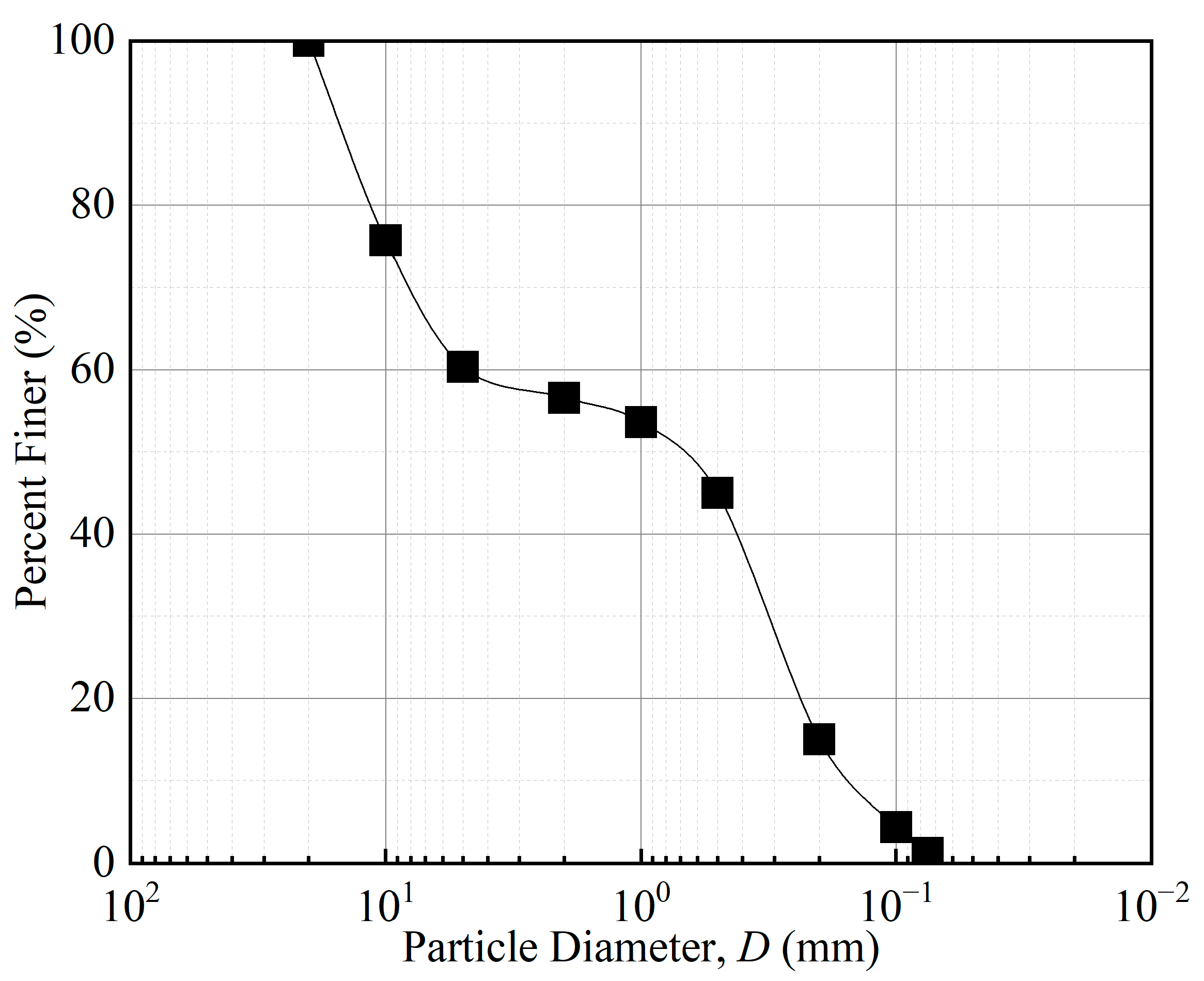
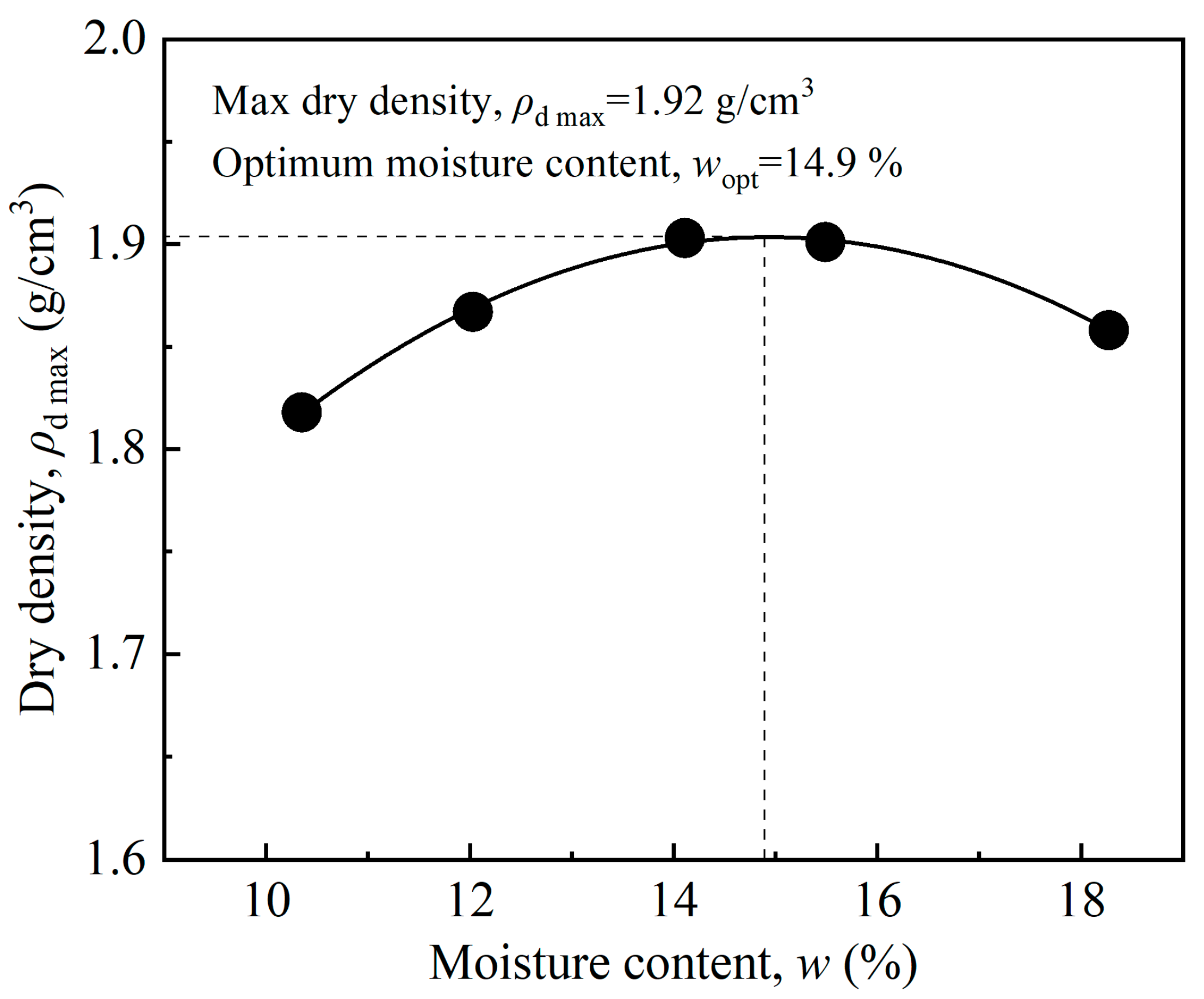
The shield residues from Central Park West to Tsubaki Xuan Avenue in the northern extension of Line 5 of the metro shield tunnel in Chongqing, China, were studied in this paper. After reviewing the relevant geological survey report, the rock type at this location is sandy mudstone and sandstone, with a strong–medium weathering degree. As the shield tunneling construction process was applied in this project, many waste shield residues with high moisture content were generated in the shield tunneling construction. As shown in Figure 1, these waste shield residues exhibit a dark yellowish-brown color. The particle size gradation curves of the wind-dried shield residues are shown in Figure 2, where the diameter of all the shield spoil is less than 2 cm, and 56.594% of the dry mass of the shield spoil is less than 2 mm in diameter. Figure 3 shows the maximum dry density compaction curves of shield residues with diameters less than 2 mm. With the increase of moisture content, the dry density of shield residues shows a trend of increasing and decreasing. The maximum dry density of shield residues is 1.92 g/cm3, and the optimum water content is 14.9%. Table 1 presents the fundamental physical properties of the shield residues with diameters less than 2 mm. The density of shield residues was 2.15 g/cm3, the dry density was 1.72 g/cm3, the liquid limit was 24.04%, and the plastic limit was 15.86%. The pH test was performed with reference to ASTM D4972 [29] standard; 10 g of air-dried shield residues and 10 g of distilled water were mixed and left for 1 h. The test was performed using the HORIBA pH/COND METER D-54 convenient pH tester. The shield residues were graded and defined as lean clay according to the particle size gradation analysis [30]. The shield residues were tested for chemical composition by X-ray fluorescence spectrometer, as shown in Table 2.
The relevant parameters of GGBS, MgO, and basalt fibers tested are listed in Table 2 and Table 3, respectively. The specific surface area and average particle size of GGBS were analyzed by the ASAP 2020 adsorption analyzer based on the nitrogen adsorption method. The activity index of GGBS was tested according to GB/T 18046 [31]. GGBS was classified and defined as S105 grade GGBS. The activity of MgO was tested by the water method, citric acid reaction method, etc. The basalt fibers in three lengths (6 mm, 9 mm, and 12 mm) of golden brown color, which are fast drawn by platinum–rhodium alloy, were produced by Bochao Engineering Materials Co., Changzhou, China.
Table 1. Properties of shield residues tested.
PropertiesStandardValue
Moisture content, w (%) 28.07
Density, ρd (g/cm3) 2.15
Dry density, ρd (g/cm3) 1.72
Specific gravity, Gs 2.63
Liquid limit, wL (%)ASTM D4318 [32]24.04
Plastic limit, wP (%)ASTM D4318 [32]15.86
Liquidity index, ILASTM D4318 [32]0.63
Plasticity index, IPASTM D4318 [32]8.18
Soil classificationASTM D2487 [30]Lean Clay
pHASTM D4927 [29]10.13
Electrical conductibility (EC, μs/cm) 325
Table 2. Chemical compositions of the shield residues, GGBS, and MgO.
Oxide ChemistrySoil (%)GGBS (%)MgO (%)
CaO1.334.00.23
SiO267.934.30.28
Al2O314.117.90.28
Fe2O35.01.020
MgO2.56.0286.3
Loss of ignition5.201.422.14
Table 3. Properties of the basalt fiber, GGBS, and MgO.
MaterialPropertiesValue
Basalt fiberLength (mm)6, 9, 12
Diameter (μm)18–20
Breaking strength (MPa)1240
Elasticity modulus (MPa)63,000
Breaking elongation (%)2.64
GGBSAlkalinity1.627
Specific surface areas (m2/g)0.2863
pH10.92
Electrical conductibility (EC, μs/cm)431.5
MgOMgO content (%)86.3%
Reactivity (s)85
Specific surface areas (m2/g)28.791
pH11.25
Electrical conductibility (EC, μs/cm)316.5

2.2. Specimen Preparation Method

The shield residues were pretreated in three procedures before being used for specimen preparation. (1) To achieve uniform distribution, the shield residues were placed in polyethylene-sealed bags for at least 24 h after being air-dried to a constant moisture content for a specific amount of time and tested for moisture content in a 105 °C oven. After being sieved through a 10 mesh screen (corresponds to 2 mm) and increasing the target moisture content, the shield residues were placed in the polyethylene-sealed bags. (2) The shield residues from step (1) and binders were combined and mixed with a geotechnical knife until there was no discernible color difference in the mixture. To further improve homogeneity, the mixture was run through the NJ-160 tabletop cement net slurry electric mixer for 5 min. The mixture was placed into polyethylene-sealed bags. The various mixing instruments were thoroughly cleaned after each mixture was created to avoid cross-contamination between multiple components. (3) Specific mass of the stabilized shield residues mix was stacked back into cylindrical molds measuring 61.8 mm in diameter, 20 mm in height, and 39.1 mm in diameter, 80 mm in height. The stabilized shield residues materials were compressed by a hydraulic jack statically. (4) To prevent moisture loss, the stabilized shield residues cylindrical specimens were immediately sealed in polyethylene bags. They were then kept in a standard maintenance room at 20 °C and 95% relative humidity until the curing time.

2.3. Experimental Procedure

2.3.1. Unconfined Compressive Strength Test

The unconfined compressive strength test was conducted with reference to ASTM D4219 [33]. (1) Both sides of the specimens were coated with petroleum jelly to prevent moisture evaporation before the test began. (2) Stabilized shield residues specimens of 39.1 mm in diameter and 80 mm in height were placed on the lower pressurized plate, and the upper pressurized plate was subsequently adjusted to touch the specimens. (3) The axial strain rate of the lower compression plate was set to 1%/min, and the test was completed within 8–10 min. (4) After the axial strain change stopped, the lower pressure plate was quickly adjusted, and the lateral limitless compressive strength test was completed.

2.3.2. Direct Shear Test

The direct shear test was carried out with reference to ASTM D3080 [34]. The impermeable plate was placed in the lower shear box, and a 61.8 mm diameter, 20 mm height mold with a stabilized shield residues specimen with a flat mouth downward was placed on the mouth of the shear box, then the specimen was slowly pushed into the shear box. The test was sheared within 3~5 min. Shear strength readings were considered complete to achieve stability or a significant reduction in the specimen shear.

2.3.3. PH Test

After the stabilized shield residues specimens were cured for the curing time, fresh specimens of a certain mass at the center of the specimens were removed. The pH tests of the stabilized shield residues specimens were carried out with regarding ASTM D4972. (1) A total of 10 g of stabilized shield residues and 10 g of distilled water were weighed, mixed with thorough stirring, and left to stand for 1 h. (2) The supernatant of the mixture was removed and tested using a Horiba D-54 PH tester.

2.3.4. Modified Dry and Soaking Cycle Test

The dry and wet cycle test was used to study the resistance of the stabilized shield residues to moisture content changes after the addition of a curing agent to the stabilized shield residues and to obtain the durability performance of the stabilized shield residues under alternating dry and wet conditions in a shorter period [35,36,37]. The dry and wet cycle test was optimized as a modified dry and soaking cycle test. The high-humidity environmental condition index in this study’s modified dry and soaking cycle test was changed and optimized compared to ASTM D4843 [38]. The pH = 5 sulfuric acid solution simulating acid rain conditions was applied to this modified dry and soaking cycle test. Low pH values were designed to simulate acidic conditions of acid rain in extreme climates [39]. Sulfate ion was designed to simulate extremely high concentrations of inorganic salts (sulfate ions for silicate cement corrosion). The significance of this test is that (1) the ability of the stabilized shield residues to resist changes in engineering properties due to moisture content changes (e.g., rainfall, drying, etc.) can be evaluated; (2) the durability performance of stabilized shield residues under long-term external alternating dry and soaking conditions can be simulated and tested in a shorter time period; (3) changes in dry and soaking alternation under the most unfavorable conditions, such as acidic conditions and high concentrations of inorganic salt corrosion conditions, can be simulated and tested.
The modified dry and soaking cycle test consisted of the following five steps: (1) The specimens of the stabilized shield residues were prepared in the same way as the specimen preparation method. Based on the variation of curing time to eliminate the effect of early hydration and to increase the focus of the dry and soaking cycle erosion results, the specimens were maintained for 90 days before the test was started. (2) Appropriate weight of sulfuric acid and appropriate weight of distilled water were thoroughly mixed. A soaking solution with a pH value of 5.0 was manufactured. (3) Stabilized shield residues specimens were placed in an electric thermostatic blast drying oven at 60 °C for 24 h. The specimens were removed, the soil debris on the surface was gently brushed away using a brush, and the specimen masses were weighed and recorded. (4) After drying, all the stabilized shield residues specimens were soaked in the soaking solution for 24 h. The specimens were removed, the water on the surface of the specimens was gently adsorbed by absorbent paper towels, and the specimen masses were weighed and recorded. (5) At the end of each soaking and dry cycle session, the stabilized shield residues specimens were removed and subjected to the pH test, the direct shear test, and unconfined compressive strength test. The remaining specimens were scheduled to continue the dry and soaking cycle test. The equations for the mass variation (MVi), cumulative mass variation (CMVi), unconfined compressive strength (qu) loss ratio (UCSLi), and shear strength (τ) loss ratio (SSLi) are listed below.
MVi = (mim0)/m0 × 100%
CMVi = MV1 + MV2 + … + MVi
UCSLi = (UCS0UCSi)/UCS0 × 100%
SSLi = (SS0SSi)/SS0 × 100%
where MVi = mass variation of stabilized shield residues specimen after the i time dry–soaking treatment. CMVi = cumulative mass variation of stabilized shield residues specimen after the first to the i time dry–soaking treatment. m0 = mass of stabilized shield residues specimen before the dry–soaking cycle test. mi = mass of stabilized shield residues specimen after the i time dry–soaking treatment. UCSLi = qu loss ratio of the stabilized shield residues specimen after the i time dry–soaking treatment. UCS0 = qu of the stabilized shield residues specimen before the modified dry and soaking cycle test. UCSi = qu of the stabilized shield residues specimen after the i time dry–soaking treatment. SSLi = τ loss ratio of the stabilized shield residues specimen after the i time dry–soaking treatment. SS0 = τ of the stabilized shield residues specimen before the modified dry and soaking cycle test. SSi = τ of stabilized shield residues specimen after the i time dry–soaking treatment.

2.3.5. Binder Material Ratio Design

Two types of specimens, fiber-stabilized shield residues and MgO-activated GGBS-fiber-stabilized shield residues, were studied in the paper. (1) Fiber-stabilized shield residues ratio test: fiber-stabilized shield residues were used to filtrate and analyze the optimal dosing of basalt fibers for stabilized shield residues. According to Boz et al. [20,40], Kim et al. [41], Li et al. [42], Tang et al. [43], and others, the optimum ratio is obtained when the fiber dosing is 0.1–0.4% of the dry mass of in situ soil for different fiber types and in situ soil properties. Table 4 shows the ratio design of fiber-stabilized shield residues. Basalt fibers were added to the shield residues in a specific ratio, and the specimens were prepared according to the previous static compression method. The results of the unconfined compressive strength test and the direct shear test were combined and the ratio of basalt fibers was analyzed. (2) MgO-activated GGBS-fiber-stabilized shield residues ratio test: the MgO to GGBS dry mass ratio was taken to be between 1:9 and 1:3 [28,44,45,46,47,48]. Table 5 presents the ratio design of MgO-activated GGBS-fiber-stabilized and cement-stabilized shield residues. Cement material was considered as the control group. Among them, the mix codes of MgO-activated GGBS-fiber-stabilized shield residues and cement-stabilized shield residues are designated as “MaGbS-c” and “CS-c” (“a” means the ratio of MgO of the MgO to GGBS, “b” means the ratio of GGBS of the MgO to GGBS, “c” means the value of the binder content). The results of the unconfined compressive strength test and direct shear test were integrated and the MgO to GGBS dry mass ratio was derived from the comprehensive analysis. (3) MgO-activated GGBS-fiber-stabilized shield residues modified dry and soaking cycle test: the optimal ratio of MgO-activated GGBS-fiber-stabilized shield residues and the control group of cement material were selected for the modified dry and soaking cycle test.

3. Results and Discussion

3.1. Fiber-Stabilized Shield Residues Ratio Test

The unconfined compressive strength (qu) and shear strength (τ) of basalt fiber-stabilized shield residues specimens with lengths of 6 mm, 9 mm, and 12 mm with different ratios of basalt fiber (each dosage with three same specimens) are shown in Figure 4. The qu and τ of the fiber-stabilized specimens were significantly higher than those of the non-fiber-stabilized specimens. Due to the incorporation of basalt fibers with shield residues, a three-dimensional mesh structure was created. The pores inside the soil were filled with fibers. The friction and structure inside the soil body were significantly enhanced. With the increase of fiber content, the qu and τ of basalt fiber-stabilized shield residues specimens showed an increase and then a decrease. With the increase of fiber length, the qu and τ of basalt fiber-stabilized stabilized shield residues specimens significantly increased. The qu of shield residues specimens with fiber content of 0.1% and fiber length of 12 mm mainly increased, which is 44% higher than that of the shield residues without basalt fiber. The qu was significantly reduced by about 17% when the fiber content increased to 0.2%. Due to the increase in fiber content, many connected damaged surfaces were created, resulting in a decrease in strength. Boz et al. [20,40] and Li et al. [42] reported a similar pattern where the qu gradually decreased with increasing fiber content. The qu was even lower than that of the shield residues specimens without fiber for 12 mm length fiber admixture of 0.4%. The variation of τ was the same as that of qu, which increased and decreased with the increase of basalt fiber content. The τ of the fiber-stabilized shield residues primarily increased at a fiber content of 0.3%, which is different from the maximum value of qu. With the increase in fiber length, the τ of shield residues gradually increased. At the same time, the ultimate value of shield residues specimens with fiber content of 0.3% at fiber lengths of 12 mm was only 3% and 1% higher than fiber content of 0.1% and 0.2%. After integrating strength tests and cost results, the basalt fiber with a 12 mm length and 0.1% content was designed as the optimal value. When the fiber-reinforced soil is subjected to external forces, the soil particles transfer the stresses to the vicinity of the fiber–soil column. The external stress is partially converted into internal forces. This prevents a rise in the overall strain of the soil sample. In this way, the interaction between fiber–soil–lime and its byproducts can be effectively combined to increase the strength of the clay while controlling the displacement and deformation of the soil particles. In previous studies, basalt fibers were shown to be more effective in improving strength at high admixture levels (~0.4%) with approximately short lengths, and at low admixture levels (~0.1%) with approximately short lengths [40,49].

3.2. MgO-Activated GGBS-Fiber-Stabilized Shield Residues Ratio Test

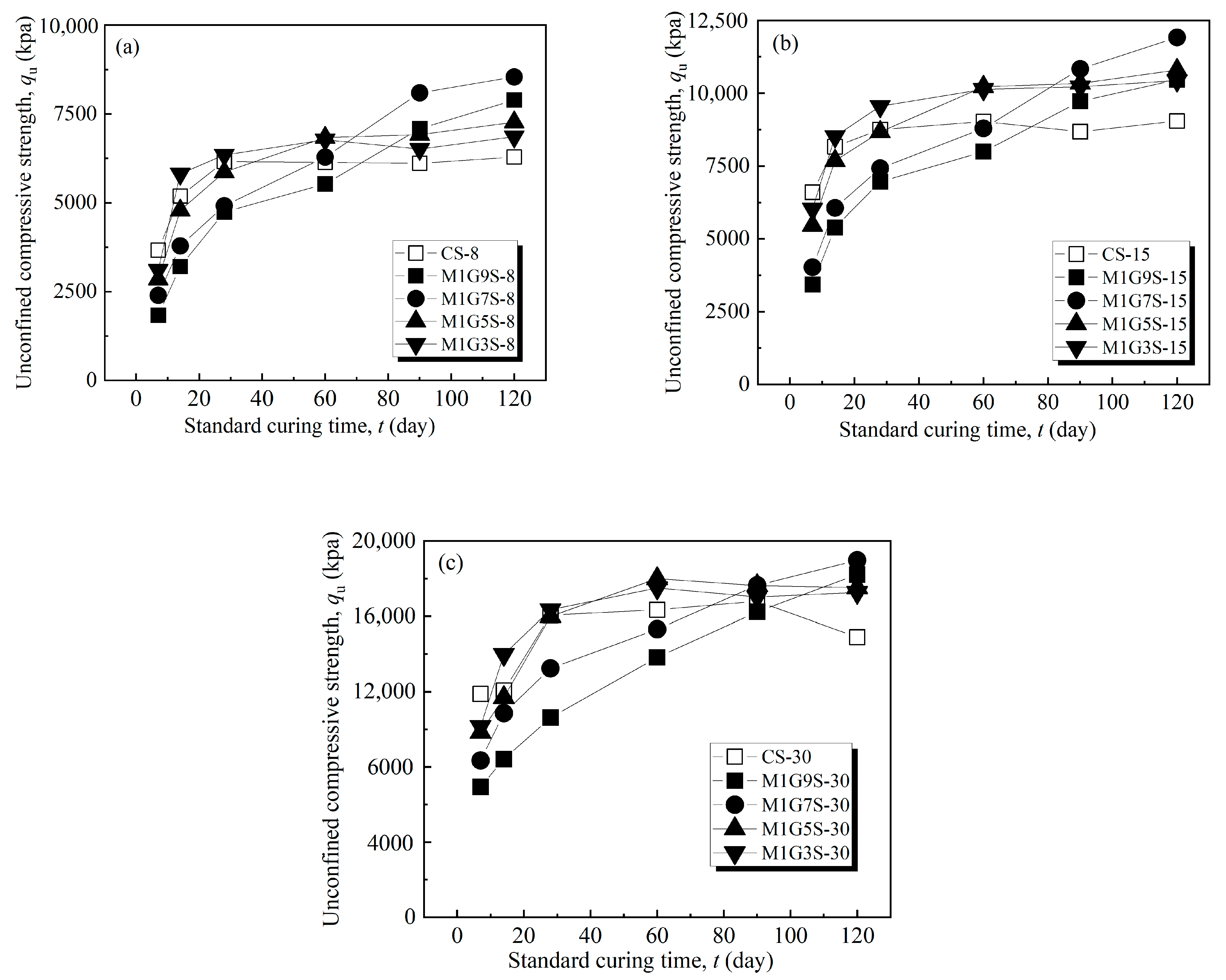
The results of the qu of the MgO-activated GGBS-fiber-stabilized shield residues specimens and the cement-stabilized shield residues specimens with different ratios of binder are shown in Figure 5. The qu of the stabilized shield residues specimens increased gradually with the increase in curing time and with the increase in binder ratio. The rise in qu of cement-stabilized shield residues was mainly provided by the first 28 days, and the qu of cement-stabilized shield residues varied less from 28 days to 120 days. The qu of MgO-activated GGBS remained stable through gradual hydration from 0 to 120 days, and the qu showed a gradual increase. This phenomenon is consistent with the results of Yi et al. [45], Yi et al. [46], and Jin et al. [28]. The 7-day qu of stabilized shield residues specimens for MgO-activated GGBS ratios is less than the qu of cement-stabilized shield residues specimens. The hydration rate of the cement-stabilized shield residues specimens in the first standard curing 28 days is more significant than that of the MgO-activated GGBS-fiber-stabilized shield residues specimens. After the standard curing time of more than 28 days, the qu of the stabilized shield residues specimens with partial MgO-activated GGBS ratio are greater than the qu of the cement-stabilized shield residues specimens. The specimens with MgO to GGBS ratios of 1:3 and 1:5 showed higher activation effects and qu within 60 days of standard curing than the other lower ratios, and the qu of the specimens with MgO to GGBS ratios of 1:3 and 1:5 gradually stabilized after 60 days. The dissolution process of MgO provides an lower alkaline environment then cement, and the covalent bonds in GGBS particles are destroyed, then the hydrated products are formed and fill the pores [50]. Lower MgO content in the binder with lower pH is not enough to activate GGBS to achieve higher early strength [45,46,48,51]. Differently, the qu of the specimens increased during 0 to 120 days of standard curing with MgO to GGBS ratios of 1:7 and 1:9. The 120-day qu of the stabilized shield residues specimens obtained the maximum value for the ratio of MgO to GGBS at 1:7 [28,44,46]. The rate of hydration is accelerated and a higher long-term strength is produced [46,50]; additionally, the rate of increment of qu of high ratio of MgO to GGBS specimens was higher than that of low ratio specimens within 60 days of standard curing, but lower after 60 days of standard curing.
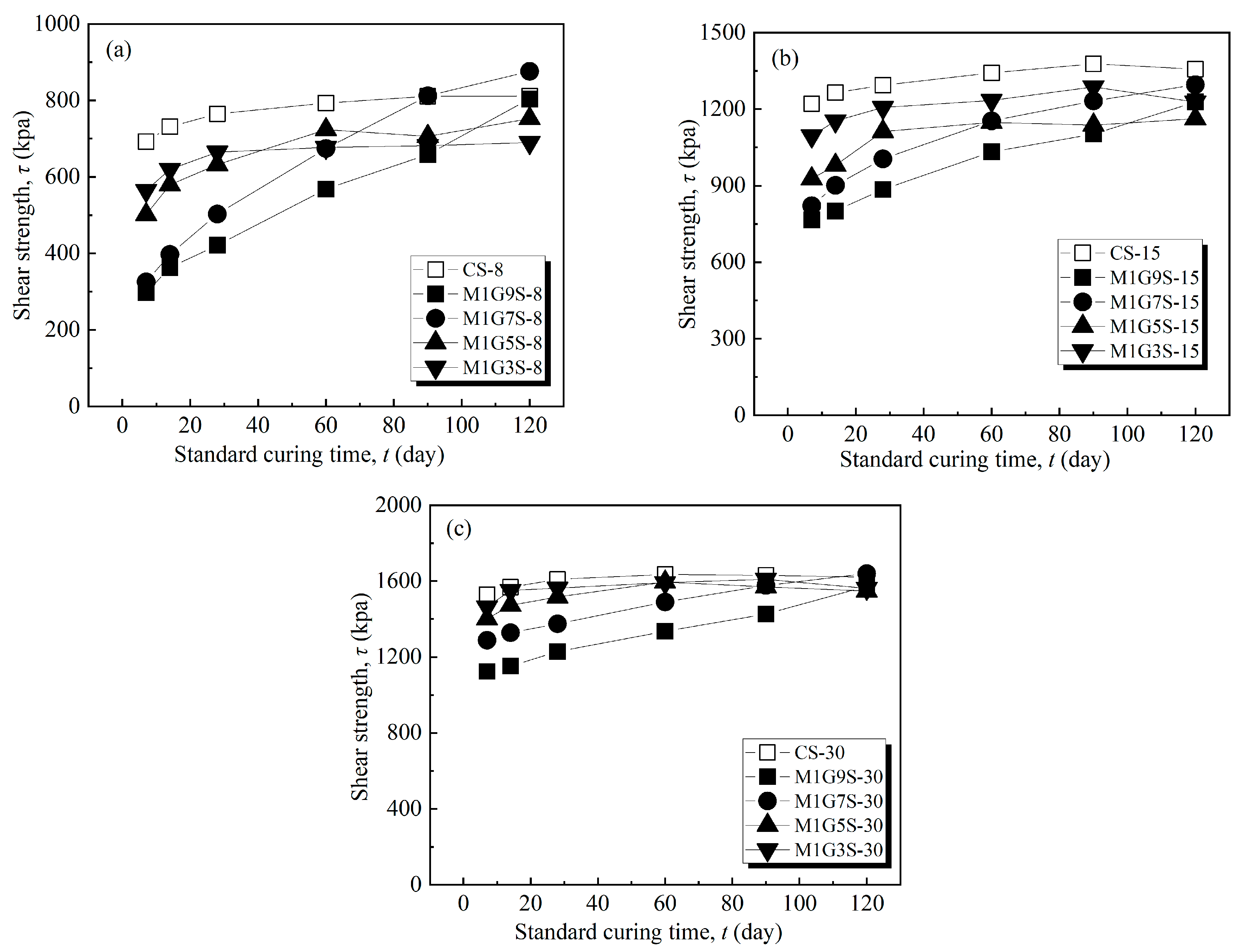
The results of the τ of the MgO-activated GGBS-fiber-stabilized shield residues specimens and the cement-stabilized shield residues specimens with different ratios of the binder are shown in Figure 6. The τ of the specimens both increase gradually with curing time, and the τ also increases with the ratio of the binder content. The difference is that the τ of the cement-stabilized shield residues specimens is higher than that of the MgO-activated GGBS-fiber-stabilized shield residues specimens during most curing time and ratios. The hydration of the cement was mainly produced in the first 28 days of the curing time. The hydration cementation of MgO-activated GGBS continued within 120 days of the curing time. The τ of the stabilized shield residues specimens with 8% and 30% MgO to GGBS ratio of 1:7 was slightly higher than that of the cement-stabilized shield residues specimens at 90 and 120 days of age. The τ of stabilized shield residues specimens with MgO to GGBS ratio of 1:7 obtained the maximum value, and the variation of the rate of increment of τ of MgO to GGBS specimens was the same as the rate of increment of qu of MgO to GGBS specimens.
The results of the pH of MgO-activated GGBS-fiber-stabilized shield residues specimens and cement-stabilized shield residues specimens during curing time are presented in Figure 7. It can be seen that the pH of the stabilized specimens both show an increasing trend with increasing curing time. The pH of cement-stabilized specimens is 11.36–12.83 and the pH of MgO-activated GGBS-fiber-stabilized shield residues specimens is 10.62–12.32 at different ratios of binder. The pH of cement-stabilized shield residues specimens is higher than the pH of MgO-activated GGBS-fiber-stabilized shield residues specimens by about 4–7% during curing time. The pH of the specimen gradually increases as the ratio of MgO to GGBS increases, and with the rise of the ratio of MgO to GGBS, the rate of increment of pH within standard curing 60 days are higher, while the rate of increment of pH after 60 days of standard curing is lower. The reason is that the total content of CaO and MgO in the MgO-activated GGBS curing specimens is lower than that of the cement component with the same content. The concentration of Ca(OH)2 in the pore water decreases after mixing MgO and GGBS with water, resulting in the pH of the MgO-activated GGBS-fiber-stabilized specimens being slightly lower than that of the cement specimens. Since the pH of MgO (pH = 11.25) is higher than that of GGBS (pH = 10.92), the pH of the specimen increases with the increase of the ratio of MgO to GGBS. In general, the MgO-activated GGBS-fiber-stabilized shield residues specimens show low pH compared with the cement-stabilized shield residues specimens, which have less environmental impact.

3.3. Modified Dry and Soaking Cycle Test

Figure 8a indicates the MV of MgO-activated GGBS-fiber-stabilized shield residues and cement-stabilized shield residues. It can be seen that the MV of the stabilized shield residues specimens generally decreases with dry–soaking cycles for two types of binder. The MV slightly decreases with dry cycle and increases with soaking cycle in one dry–soaking cycle. The MV of cement-stabilized shield residues is always less than 0; however, the MV of MgO-activated GGBS-fiber-stabilized shield residues increases first and then decreases and maintains mass growth during the soaking cycle. The MV of the cement-stabilized shield residues specimen is slightly greater than that of the MgO-activated GGBS-fiber-stabilized shield residues specimen, which shows a higher MV than that of the cement-stabilized shield residues specimen. Figure 8b manifests that the CMV of the MgO-activated GGBS-fiber-stabilized shield residues specimen is more than zero, while the CMV of the cement-stabilized shield residues specimen is negative. The mass of the MgO-activated GGBS-fiber-stabilized shield residues gradually increases under dry and soaking cycles of immersion. The difference in CMV between the two specimens after ten dry and soaking cycles is more than 20%. These phenomena are attributed to that the MgO-activated GGBS-fiber-stabilized shield residues exhibit greater resistance to dry and soaking erosion compared to the cement-stabilized shield residues.
Figure 9 presents the variation of pH of MgO-activated GGBS-fiber-stabilized shield residues specimens and cement-stabilized shield residues specimens with dry and soaking cycles and the standard curing time. Usually, the pH of stabilized specimens increases gradually with the curing time. However, the pH values of MgO-activated GGBS-fiber-stabilized shield residues and cement-stabilized shield residues gradually decrease with increasing dry and soaking cycles. This is attributed to the following possible reasons. (1) The immersion environment in the dry and soaking cycles is acidic with a pH of 5. (2) The consumption of OH is required to evolve the volcanic ash reaction in the stabilized shield residues associated with the dry and soaking cycle. After ten cycles of dry and soaking, the pH of cement-stabilized shield residues specimens decreases from 11.89 to 10.31 with 13% reduction, while the pH value of the MgO-activated GGBS-fiber-stabilized shield residues specimens decreases from 11.21 to 9.88 with a change of 12%.
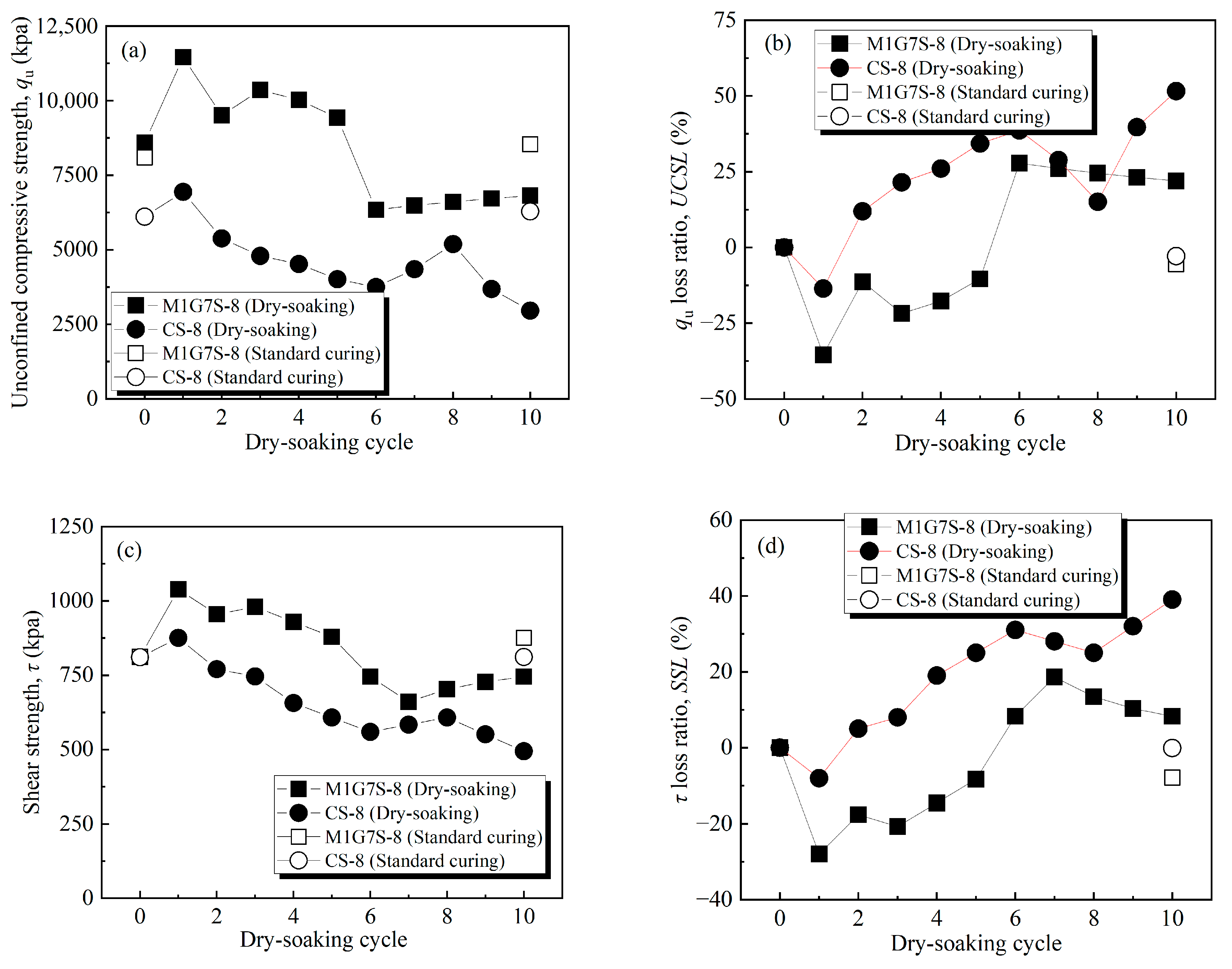
The variation patterns of qu, τ, UCSLi, and SSLi for dry and soaking cycles and standard curing of MgO-activated GGBS-fiber-stabilized shield residues specimens and cement-stabilized shield residues specimens are shown in Figure 10. The qu and τ of the stabilized specimens basically show a trend of increasing and then decreasing with the increase of dry and soaking cycles. At the end of the first dry and soaking cycle, the sulfate erosion had not yet affected the internal hydration reaction of the specimens. With the increase of dry and soaking cycles, the qu and τ of the stabilized specimens begin to decrease and are lower than those before the dry and soaking cycle soaking. The qu and τ of the MgO-activated GGBS-fiber-stabilized shield residues specimens are both lower after the sixth dry and soaking cycles than before the dry and soaking cycle. In contrast, the qu and τ of cement-stabilized shield residues specimens exhibit a pattern of lower strength after the second dry and soaking cycles than before the test. After ten dry and soaking cycles, the qu and τ of the MgO-activated GGBS-fiber-stabilized shield residues specimens were reduced by 22% and 8%, respectively, compared to those corresponding to the standard curing time. In contrast, the qu and τ of cement-stabilized shield residues specimens were reduced by 52% and 39%.
The MgO-activated GGBS-fiber-stabilized shield residues specimens exhibit better durability performance compared to the cement-stabilized shield residues specimens in the modified dry and soaking cycle test. This may be attributed to the following reasons: (1) The appropriate ratio of basalt fibers can effectively strengthen the internal skeleton structure of the shield residues and form a three-dimensional mesh structure. In addition, the durability performance of the dry and wet cycles of the stabilized specimens can be effectively enhanced by the friction and cementation between the fibers and the shield residues/hydration cementation products, reducing the number and volume of internal fractures in the soil produced by the action of dry and soaking cycles [40,42,43,52]. (2) MgO-activated GGBS-stabilized soils have a greater proportion of mesopores than cement-stabilized soils [53,54]. MgO-activated GGBS-stabilized shield residues produce less shrinkage deformation under dry and soaking cycles stress compared to cement-stabilized shield residues. (3) The Al2O3 and SiO2 contents of GGBS are higher than those of cement, and the volcanic ash reaction in GGBS is more durable under MgO activation [55]. The specific surface area of cement is about 300 m2/kg, while the specific surface area of GGBS can reach 400–450 m2/kg [56]. (4) SO42− in the solution can combine with Ca2+ and Al3+ in the soil to form calcium ettringite (Aft), which expands in volume and generates swelling stresses to destroy the structure of the cement-stabilized soil [57,58]. The AFt generated by the reaction of MgO-activated GGBS-stabilized soils under the soaking conditions of sulfate ion solution will fill the pores of soil particles [58,59,60]. As seen in Figure 8, the significant increase in strength of the MgO-activated GGBS-fiber-stabilized shield residues specimens was between the initial stage and fifth dry and soaking cycles, indicating that the ettringite generated at the beginning of curing soaking enhanced the strength of the stabilized shield residues relative to standard curing due to its pore filling effect. With the increase of dry and soaking cycles, the volume expansion of calcium alumina still produces damage to the structure of stabilized specimens.

4. Summary and Conclusions

Based on the experimental results in this paper, the following conclusions can be drawn.
(1) The unconfined compressive strength (qu) and shear strength (τ) of fiber-stabilized shield residues specimens both increased with the increase of fiber length and showed an increase and decrease with the addition of fiber content. Integrating the strength test results, the basalt fiber with 12 mm length and 0.1% ratio was designed as the optimal value, and the strength of the shield residues specimens was increased by 44% compared with that of the non-fiber-stabilized shield residues specimens.
(2) The MgO-activated GGBS-fiber-stabilized shield residues specimens with the ratio of MgO to GGBS at 1:7 displayed higher qu and τ with standard curing time. The pH of the MgO-activated GGBS-fiber-stabilized shield residues specimens was 4.0–5.4% lower than that of the cement-stabilized shield residues specimens. The MgO-activated GGBS-fiber-stabilized shield residues specimens showed low pH compared with the cement-stabilized shield residues specimens, which have less impact on the environment. Additionally, the rate of increment of qu, τ, and pH of high ratio of MgO to GGBS specimens was higher than that of low-ratio specimens within 60 days of standard curing, but lower after 60 days of standard curing.
(3) The absolute value of mass variation (MV) and cumulative mass variation (CMV) of the MgO-activated GGBS-fiber-stabilized shield residues specimens and cement-stabilized shield residues specimens gradually increased with dry–soaking cycles. However, the MV and CMV of the former was higher, and the difference in CMV between the two specimens after ten dry and soaking cycles was more than 20%. The pH values of MgO-activated GGBS-fiber-stabilized shield residues and cement-stabilized shield residues gradually decreased with the increase of dry–soaking cycles. The qu and τ of the stabilized specimens basically showed a trend of increasing and then decreasing with the rise of dry and soaking cycles. After ten dry–soaking cycles, the qu, τ, and pH of the MgO-activated GGBS-fiber-stabilized shield residues specimens decreased by 21%, 8%, and 12%, respectively, compared to those corresponding to the standard curing time. In contrast, the qu, τ, and pH of cement-stabilized shield residues specimens were reduced by 46%, 39%, and 13%.

Author Contributions

Conceptualization, Z.-Y.J. and Y.-Z.L.; methodology, Z.-Y.J. and Y.-Z.L.; software, W.C., J.Z. and C.C.; validation, Z.-Y.J. and Y.-Z.L.; formal analysis, W.C., J.Z. and C.C.; investigation, W.C., J.Z. and C.C.; resources, Z.-Y.J. and Y.-Z.L.; data curation, W.C., J.Z. and C.C.; writing—original draft preparation, W.C., J.Z. and C.C.; writing—review and editing, Z.-Y.J. and Y.-Z.L.; visualization, W.C., J.Z. and C.C.; supervision, Z.-Y.J. and Y.-Z.L.; project administration, Z.-Y.J. and Y.-Z.L.; funding acquisition, Z.-Y.J. and Y.-Z.L. All authors have read and agreed to the published version of the manuscript.

Funding

This research was funded by the National Natural Science Foundation of China (Grant No. 41877266, No. 41521002), the Science Foundation for Distinguished Young Scholars of Sichuan Province (Grant No. 2020JDJQ0044).

Data Availability Statement

The data that support the findings of this study are available from the corresponding author, Zhe-Yuan Jiang, upon reasonable request.

Acknowledgments

We wish to thank the anonymous referees for their careful reading and providing insightful comments to improve the initial version of this paper.

Conflicts of Interest

The authors declare no conflict of interest.

References

  1. Hong, K.R. Development and Thinking of Tunnels and Underground Engineering in China in Recent 2 Years (From 2017 to 2018). Tunn. Constr. 2019, 39, 710–723. [Google Scholar]
  2. Xiao, M.Q. Representative projects and development trend of underwater shield tunnels in china. Tunn. Constr. 2018, 38, 360–367. [Google Scholar]
  3. China Association of Metros. Statistical and Analytical Report of China Urban Rail Transit in 2017; China Association of Metros: Beijing, China, 2018; pp. 1–32. (In Chinese) [Google Scholar]
  4. Ooishi, Y.; Murakawa, S.; Hatakoshi, A.; Mori, T. Development of discharged soil measuring device for shield tunneling machines. J. Terramechanics 1992, 29, 465–475. [Google Scholar] [CrossRef]
  5. Oggeri, C.; Fenoglio, T.M.; Vinai, R. Tunnel spoil classification and applicability of lime addition in weak formations for muck reuse. Tunn. Undergr. Space Technol. 2014, 44, 97–107. [Google Scholar] [CrossRef]
  6. Grohs, H. Cost-efficient regeneration of bore slurry for driving of the weser tunnel. Aufbereitungstechnik 2002, 43, 30–37. [Google Scholar]
  7. Zhou, S.; Li, X.; Ji, C.; Xiao, J. Back-fill grout experimental test for discharged soils reuse of the large-dayiameter size slurry shield tunnel. KSCE J. Civ. Eng. 2017, 21, 725–733. [Google Scholar] [CrossRef]
  8. Blengini, G.A.; Garbarino, E.; Solar, S.; Shields, D.J.; Hámor, T.; Vinai, R.; Agioutantis, Z. Life cycle assessment guidelines for the sustainable production and recycling of aggregates: The Sustainable Aggregates Resource Management Project (SARMa). J. Clean. Prod. 2012, 27, 177–181. [Google Scholar] [CrossRef]
  9. Bellopede, R.; Marini, P. Aggregates from tunnel muck treatments. Properties and uses. Physicochem. Probl. Miner. 2011, 47, 259–266. [Google Scholar]
  10. Riviera, P.P.; Bellopede, R.; Marini, P.; Bassani, M. Performance-based re-use of tunnel muck as granular material for subgrade and sub-base formation in road construction. Tunn. Undergr. Space Technol. 2014, 40, 160–173. [Google Scholar] [CrossRef] [Green Version]
  11. Guo, W.S.; Wang, B.Q.; Li, Y.Z.; Mo, S. Status quo and prospect of harmless disposal and reclamation of shield muck in China. Tunn. Constr. 2020, 40, 1101. [Google Scholar]
  12. Du, L.; Feng, Y.; Lu, W.; Kong, L.; Yang, Z. Evolutionary game analysis of stakeholders’ decision-making behaviours in construction and demolition waste management. Environ. Impact Assess. 2020, 84, 106408. [Google Scholar] [CrossRef]
  13. Zhu, W.; Qian, Y.J.; Wang, L.; Wei, B.; Lu, K.J.; Fang, Z.Q.; Meng, L.F. Classification, treatment, and utilization techniques of shield tunnel abandoned soil and related issues. Tunn. Constr. 2021, 41, 1–13. [Google Scholar]
  14. Tanner, S.; Katra, I.; Argaman, E.; Ben-Hur, M. Erodibility of waste (Loess) soils from construction sites under water and wind erosional forces. Sci. Total Environ. 2018, 616–617, 1524. [Google Scholar] [CrossRef] [PubMed]
  15. Yin, Y.; Li, B.; Wang, W.; Zhan, L.; Xue, Q.; Gao, Y.; Zhang, N.; Chen, H.; Liu, T.; Li, A. Mechanism of the December 2015 Catastrophic Landslide at the Shenzhen Landfill and Controlling Geotechnical Risks of Urbanization. Engineering 2016, 2, 230–249. [Google Scholar] [CrossRef] [Green Version]
  16. Entacher, M.; Resch, D.; Reichel, P.; Galler, R. Recycling of tunnel spoil—Laws affecting waste from mining and tunnelling. J. Geomech. Tunnelbau. 2011, 4, 692–701. [Google Scholar] [CrossRef]
  17. Ding, Z.Y.; Liu, T.; Zhang, Y.; Su, X.T.; Zheng, J.G. The Curing and Strength Properties of Highly Moist Waste Mud from Slurry Shield Tunnel Construction. Appl. Sci. 2022, 12, 3762. [Google Scholar] [CrossRef]
  18. Shi, Q.T.; Wu, W.Q.; Lu, Y. Mixing Proportion and Working Mechanism of Inorganic Binder-Waste Slurry Composite Cementing Materials. Tunn. Constr. 2020, 40, 629–635. [Google Scholar]
  19. Yang, A.W.; Wang, T.; Xu, Z.L. Experimental study on lime and its additional agent to cure tianjin marine soft soil. Eng. Geol. 2015, 23, 996–1004. [Google Scholar]
  20. Boz, A.; Sezer, A.; Özdemir, T.; Hızal, G.E.; Azdeniz Dolmacı, Ö. Mechanical properties of lime-treated clay reinforced with different types of randomly distributed fibers. Arab. J. Geosci. 2018, 11, 122. [Google Scholar] [CrossRef]
  21. Higgins, D.D. Soil Stabilisation with Ground Granulated Blastfurnace Slag; Cementitious Slag Makers Association (CSMA): London, UK, 2005; Volume 1, p. 15. [Google Scholar]
  22. Swamy, R.N. Cement Replacement Materials; Surrey University Press: Surrey, UK, 1986. [Google Scholar]
  23. Cheng, F.A.; Wei, R.L.; Li, H. Status of recycling technology of blast furnace slag. J. Xi’an Univ. Archit. Technol. (Nat. Sci.). 2010, 42, 446–450. (In Chinese) [Google Scholar]
  24. Wang, X.J.; Lu, W.X.; Shao, X. Progress in granulated blast furnace slay used as admixture for high performance concrete. J. Shanghai Univ. (Nat. Sci.) 2004, 10, 170–175. [Google Scholar]
  25. Li, W.T.; Li, R.X.; Chen, Y.; Xiao, H.L. Comparison of Two Sulfate-Bearing Soils Stabilized with Reactive Magnesia-Activated Ground Granulated Blast Furnace Slag: Swelling, Strength, and Mechanism. Buildings 2023, 13, 230. [Google Scholar] [CrossRef]
  26. Zhang, M.T.; Zhao, M.; Tan, K.F. Experimental study on the new non-clinker slag cement. Bull. Chin. Ceram. Soc. 2011, 30, 920–924. [Google Scholar]
  27. Haha, M.B.; Lothenbach, B.; Saout, G.L. Influence of slag chemistry on the hydration of alkali-activated blast-furnace slag—Part I: Effect of MgO. Cem. Concr. Res. 2011, 41, 955–963. [Google Scholar] [CrossRef]
  28. Jin, F.; Al-Tabbaa, A. Evaluation of novel reactive MgO activated slag binder for the immobilisation of lead and zinc. Chemosphere 2014, 117, 285–294. [Google Scholar] [CrossRef] [Green Version]
  29. ASTM D4972; Standard Test Methods for pH of Soils. ASTM: West Conshohocken, PA, USA, 2019.
  30. ASTM D2487; Standard Test Methods for Classification of Soils for Engineering Purposes (Unified Soil Classification System). ASTM: West Conshohocken, PA, USA, 2017.
  31. GB/T 18046; Ground Granulated Blast Furnace Slag Used for Cement, Mortar and Concrete. Standardization Administration of the People’s Republic of China Press: Beijing, China, 2017.
  32. ASTM D4318; Standard Test Methods for Liquid Limit, Plastic Limit, and Plasticity Index of Soils. ASTM: West Conshohocken, PA, USA, 2017.
  33. ASTM D4219; Standard Test Method for Short-Term Unconfined Compressive Strength Index of Chemically Grouted Soils. ASTM: West Conshohocken, PA, USA, 2022.
  34. ASTM D3080/D3090M-11; Standard Test Method for Direct Shear Test of Soils Under Consolidated Drained Conditions (Withdrawn 2020). ASTM: West Conshohocken, PA, USA, 2011.
  35. Kamon, M.; Nontananandh, S.; Katsumi, T. Utilization of stainless-steel slag by cement hardening. Soils Found. 1993, 33, 118–129. [Google Scholar] [CrossRef] [Green Version]
  36. Darve, F.; Vardoulakis, I. Degradations and Instabilities in Geomaterials; Springer: New York, NY, USA, 2014. [Google Scholar]
  37. Shihata, S.; Baghdadi, Z. Long-term strength and durability of soil cement. J. Mater. Civ. Eng. 2001, 13, 161–165. [Google Scholar] [CrossRef]
  38. ASTM D4843-88; Standard Test Method for Wetting and Drying Test of Solid Wastes. ASTM: West Conshohocken, PA, USA, 2016.
  39. Kamon, M.; Ying, C.Y.; Katsumi, T. Effect of acid rain on lime and cement stabilized soils. J. Soils Found. 1996, 36, 91–99. [Google Scholar] [CrossRef] [PubMed] [Green Version]
  40. Boz, A.; Sezer, A. Influence of fibre type and content on freeze-thaw resistance of fibre stabilized lime stabilized clay. Cold Reg. Sci. Technol. 2018, 151, 359–366. [Google Scholar] [CrossRef]
  41. Kim, B.; Kim, Y. Strength characteristics of cemented sand-bentonite mixtures with fibre and metakaolin additions. Mar. Georesour. Geotechnol. Taylor Francis 2017, 35, 414–425. [Google Scholar] [CrossRef]
  42. Li, J.; Tang, C.S.; Wang, D.Y.; Pei, X.J.; Shi, B. Effect of discrete fibre reinforcement on soil tensile strength. J. Rock Mech. Geotech. 2014, 6, 133–137. [Google Scholar] [CrossRef] [Green Version]
  43. Tang, C.; Shi, B.; Gao, W. Strength and mechanical behavior of short polypropylene fibre stabilized and cement stabilized clayey soil. Geotext. Geomembr. 2007, 25, 194–202. [Google Scholar] [CrossRef]
  44. Gruskovnjak, A.; Lothenbach, B.; Winnefeld, F. Hydration mechanisms of super sulphated slag cement. Cem. Concr. Res. 2008, 38, 983–992. [Google Scholar] [CrossRef] [Green Version]
  45. Yi, Y.; Liska, M.; Al-Tabbaa, A. Initial Investigation into the Use of GGBS-MgO in Soil Stabilisation. In Grouting and Deep Mixing; American Society of Civil Engineers: New Orleans, LA, USA, 2012; pp. 444–453. [Google Scholar]
  46. Yi, Y.; Liska, M.; Al-Tabbaa, A. Properties of two model soils stabilized with different blends and contents of GGBS, MgO, lime, and PC. J. Mater. Civ. Eng. 2014, 26, 267–274. [Google Scholar] [CrossRef]
  47. Yi, Y.; Li, C.; Liu, S. Alkali-activated ground-granulated blast furnace slag for stabilization of marine soft clay. J. Mater. Civ. Eng. 2015, 27, 04014146. [Google Scholar] [CrossRef]
  48. Yi, Y.; Zheng, X.; Liu, S.Y.; Al-Tabbaa, A. Comparison of reactive magnesia-and carbide slag-activated ground granulated blastfurnace slag and Portland cement for stabilisation of a natural soil. Appl. Clay Sci. 2015, 111, 21–26. [Google Scholar] [CrossRef]
  49. Wang, D.; Wang, H.; Larsson, S.; Benzerzour, M.; Maherzi, W.; Amar, M. Effect of basalt fiber inclusion on the mechanical properties and microstructure of cement-solidified kaolinite. Constr. Build. Mater. 2020, 241, 118085. [Google Scholar] [CrossRef]
  50. Zheng, J.R.; Sun, X.X.; Guo, L.J.; Zhang, S.M.; C, J.Y. Strength and hydration products of cemented paste backfill from sulphide-rich tailings using reactive MgO-activated slag as a binder. Constr. Build. Mater. 2019, 203, 111–119. [Google Scholar] [CrossRef]
  51. Estabragh, A.R.; Jahani, A.; Javadi, A.A.; Babalar, M. Assessment of different agents for stabilisation of a clay soil. Int. J. Pavement. Eng. 2022, 23, 160–170. [Google Scholar] [CrossRef]
  52. Sun, X.P.; Ding, Z.H.; Bi, Y.Z.; Wang, X.Y. Water-Holding Properties of Clinoptilolite/Sodium Polyacrylate-Modified Compacted Clay Cover of Tailing Pond. Int. J. Environ. Res. Public Health 2022, 19, 15554. [Google Scholar] [CrossRef]
  53. Collins, F.; Sanjayan, J.G. Effect of pore size distribution on drying shrinking of alkali-activated slag concrete. Cem. Concr. Res. 2000, 30, 1401–1406. [Google Scholar] [CrossRef]
  54. Jin, F.; Gu, K.; Al-Tabbaa, A. Strength and drying shrinkage of reactive MgO modified alkali-activated slag paste. Constr. Build. Mater. 2014, 51, 395–404. [Google Scholar] [CrossRef]
  55. Li, J.L. Application of cement soil pile composite foundation. J. Highw. 2012, 1, 86–88. (In Chinese) [Google Scholar]
  56. Inthurraide, G.J.B.; Oliver, J. High performance concrete for French Nuclear Reactor Containment Vessels. J. Util. High Strength Concr. 1993, 1, 20–24. [Google Scholar]
  57. Fu, X.Q.; Feng, J.D.; Xie, Y.J. Mechanical behavior of soil cement under ambient with sulfate conditions. Rock Soil Mech. 2008, 29 (Suppl. S1), 659–662. (In Chinese) [Google Scholar]
  58. Rollings, R.; Burkes, J.; Rollings, M. Sulfate attack on cement-stabilized sand. J. Geotech. Geoenviron. 1999, 125, 364–372. [Google Scholar] [CrossRef]
  59. Wild, S.; Kinuthia, J.M.; Jones, G.I. Effects of partial substitution of lime with ground granulated blast furnace slag (GGBS) on the strength properties of lime-stabilised sulphate-bearing clay soils. Eng. Geol. 1998, 51, 37–53. [Google Scholar] [CrossRef]
  60. Wild, S.; Kinuthia, J.M.; Jones, G.I. Suppression of swelling associated with ettringite formation in lime stabilized sulphate bearing clay soils by partial substitution of lime with ground granulated blastfurnace slag (GGBS). Eng. Geol. 1999, 51, 257–277. [Google Scholar] [CrossRef]
Figure 1. Shield residues.
Buildings 13 00738 g001
Figure 2. Particle size distribution curve of shield residues.
Buildings 13 00738 g002
Figure 3. Compaction curve of shield tunnel abandoned soil.
Buildings 13 00738 g003
Figure 4. Variations of (a) unconfined compressive strength (qu) and (b) shear strength (τ) with different lengths and ratios of basalt fiber.
Buildings 13 00738 g004
Figure 5. Variations of unconfined compressive strength (qu) with different ratios of binder on (a) 8%, (b) 15%, and (c) 30%.
Buildings 13 00738 g005
Figure 6. Variations of shear strength (τ) with different ratios of binder on (a) 8%, (b) 15%, and (c) 30%.
Buildings 13 00738 g006
Figure 7. Variations of pH with different ratios of binder on (a) 8%, (b) 15%, and (c) 30%.
Buildings 13 00738 g007
Figure 8. Variations of (a) MV and (b) CMV with dry–soaking cycle for shield residues stabilized by M1G7-8 and CS-8 with dry–soaking cycle.
Buildings 13 00738 g008
Figure 9. Variations of pH with dry–soaking cycle for shield residues stabilized by M1G7-8 and CS-8.
Buildings 13 00738 g009
Figure 10. Variations of (a) unconfined compressive strength (qu); (b) unconfined compressive strength loss ratio (UCSLi); (c) shear strength (τ); and (d) shear strength loss ratio (SSLi) with dry–soaking cycle for shield residues stabilized by M1G7-8 and CS-8.
Buildings 13 00738 g010
Table 4. Ratio design of the fiber-stabilized shield residues.
Fiber Length (mm)Fiber Content (%)Dry Density (%)Moisture Content (%)
60.11.915
60.21.915
60.31.915
60.41.915
90.11.915
90.21.915
90.31.915
90.41.915
120.11.915
120.21.915
120.31.915
120.41.915
Table 5. Ratio design of MgO-activated GGBS-fiber-stabilized and cement-stabilized shield residues.
Mix CodeBinder Content (%)MgO to GGBS Fiber Content (%)Fiber Length (mm)Dry Density (%)Moisture Content (%)
M1G9S-881:90.1121.915
M1G7S-881:70.1121.915
M1G5S-881:50.1121.915
M1G3S-881:30.1121.915
M1G9S-15151:90.1121.915
M1G7S-15151:70.1121.915
M1G5S-15151:50.1121.915
M1G3S-15151:30.1121.915
M1G9S-30301:90.1121.915
M1G7S-30301:70.1121.915
M1G5S-30301:50.1121.915
M1G3S-30301:30.1121.915
CS-880001.915
CS-15150001.915
CS-30300001.915
Disclaimer/Publisher’s Note: The statements, opinions and data contained in all publications are solely those of the individual author(s) and contributor(s) and not of MDPI and/or the editor(s). MDPI and/or the editor(s) disclaim responsibility for any injury to people or property resulting from any ideas, methods, instructions or products referred to in the content.