Article

Analysis of Bearing Safety and Influencing Factors of Supporting Structures of Hydraulic Tunnels in Cold Regions Based on Frost Heave

1
College of Hydraulic and Civil Engineering, Xinjiang Agriculture University, Urumqi 830052, China
2
College of Water Conservancy & Architectural Engineering, Shihezi University, Shihezi 832003, China
3
Department of Architectural Engineering, Zhejiang Tongji Vocational College of Science and Technology, Hangzhou 311200, China
*
Author to whom correspondence should be addressed.
Buildings 2023, 13(2), 544; https://doi.org/10.3390/buildings13020544
Submission received: 22 January 2023 / Revised: 11 February 2023 / Accepted: 14 February 2023 / Published: 16 February 2023
(This article belongs to the Special Issue Strength and Performance of Building Materials)

Abstract

:
In order to study the bearing safety and influencing factors of the support structures of hydraulic tunnels in cold regions under the action of low-temperature frost heave, a mechanical model of the support structure and surrounding rock was established. Taking a hydraulic tunnel of a hydropower station in Xinjiang as the research object, a combination of field measurement and a numerical simulation method was adopted to study the bearing safety of the support structure during a period of freezing weather. Based on this model, the effects of different thermal expansion coefficients, temperature differences, and surrounding rock porosity on the bearing safety of the support structure in the low-temperature region were studied. From the calculation results, it was concluded that the simulation results of the numerical model established by using the mechanical model in this paper were in good agreement with the actual measurement results of the project. The circumferential freezing and compressive stresses at the arch waist of the supporting structure of the project were the largest, and significant plastic strain was generated near the arch waist. The displacement at the arch of the supporting structure was the largest, while the weak points were at the arch waist and arch top of the supporting structure. The coefficient of thermal expansion, greater temperature difference, and increased porosity of the surrounding rock all led to an increase in the rock freezing and swelling force to varying degrees, thus reducing the load-bearing safety of the supporting structure. The research results could provide a theoretical basis and a reliable mechanical and numerical simulation model for establishing the bearing safety of tunnels in the cold region.

1. Introduction

Under the “One Belt, One Road” construction initiative, the construction of hydraulic tunnels in the cold region of western China is gradually increasing, and the impact of low-temperature frost heave on the tunnels is becoming more prominent. The lining structure is divided into two types, due to the frost heave damage that can occur outside and inside the wall. Frost heave increases the stress difference in the lining, which is one of the main ways it damages tunnels in cold regions [1,2,3,4,5,6]. The study of the load-bearing safety of the supporting structures under frost heave and its influencing factors is of great significance for the prevention of tunnel frost heave damage in cold regions.
At present, shotcrete support is widely used in the construction of tunnels and other tunnel projects in cold regions. In recent years, many scholars have conducted research on the strength and load-bearing capacity of low-temperature concrete supporting structures. Among them, Li Yan et al. [7] determined the strength development rule of concrete at −10 °C under standard curing conditions through experiments, and obtained the calculation formula of its early maturity through calculation; Dai Jinpeng et al. [8] directly used exponential function, hyperbolic function, and logarithmic function models to establish the relationship between compressive strength and maturity under standard curing conditions, and obtained the calculation formula for predicting concrete strength at different maturity under low temperature curing conditions; Li Wei et al. [9] studied the change rule of the initial thermal conductivity of concrete support structure with the number of freeze–thaw cycles through numerical simulation. The force changes in the supporting structure caused by tunnel frost heave in cold regions are mainly due to the action of frost heave pressure generated by in-situ water freezing in the surrounding rock [10]. Feng Qiang and Lv Zhitao et al. [11,12,13] deduced the elastic-plastic analytical solution of the tunnel surrounding rock and support structure under the action of isotropic and anisotropic frost heave. Peng Xiaoli et al. [14] analyzed the change law of surrounding rock freezing circle and frost heave force with time and temperature under the effect of low-temperature water–ice phase change through theoretical calculation and numerical simulation. However, the above theoretical analysis assumes that the support structure is an elastic material, which can calculate the force situation of the support structure but cannot determine its bearing safety. Therefore, Zeng Yu et al. [15] converted the constitutive model in the design code of concrete structures to make it correspond to the concrete damaged plasticity constitutive model in ABAQUS. The availability of using plastic strain values to determine the plasticity parameters of concrete damage for various strength classes was determined by calculation and experiment. Qi Hu et al. [16] carried out the secondary development of the elastic-plastic constitutive model in ABAQUS through the subroutine UMAT. The elastic-plastic damage constitutive model can reflect the failure process of the structure in real-time, which is convenient for the analyst to grasp the failure form of the structure intuitively. To address the influence of frost heave and supporting structure forces, Yu Qingyang et al. [17] derived the analytical equation for frost heave pressure in cold region tunnels based on the overall frost heave mechanical model of the freeze–thaw circle. The analytical equation of frost heave pressure in cold region tunnels was derived and the effect of different influencing factors on frost heave pressure was investigated by using the control variable method. From the results, it is concluded that the frost heave rate has the greatest influence on frost heave pressure, followed by the frost heave depth, while the thickness of the lining has the least influence. Zhang Yuwei et al. [18] established the frost heave model of the broken circle and used the control variable method to analyze the relationship between the frost heave force and influencing factors. They concluded that the influence of factors on frost heave force was: freezing depth > frost heave rate of freeze–thaw circle > elastic equivalent resistance coefficient of lining. At present, research on hydraulic tunnels in cold regions mainly focuses on the strength and bearing capacity of the concrete supporting structures under low-temperature frost heave, the stress change of the supporting structure, and the factors that influence partial frost heave and supporting structures. There is less research on the bearing safety of supporting structures under low-temperature frost heave.
In this paper, based on previous research, the supporting structure of a cold region hydropower station transmission tunnel in Xinjiang is taken as the research object, and the frost heave of the supporting structure of the tunnel is numerically simulated, with the monitoring temperature value of the tunnel used as the temperature field variable. The stresses and strains on the supporting structure are used to determine its load-carrying safety. The effects of the thermal expansion coefficient, temperature difference, and initial porosity on the bearing safety of the supporting structure of the surrounding rock are also calculated and analyzed in order to provide a theoretical basis and a reliable mechanical and numerical simulation model for the bearing safety of tunnels in cold regions.

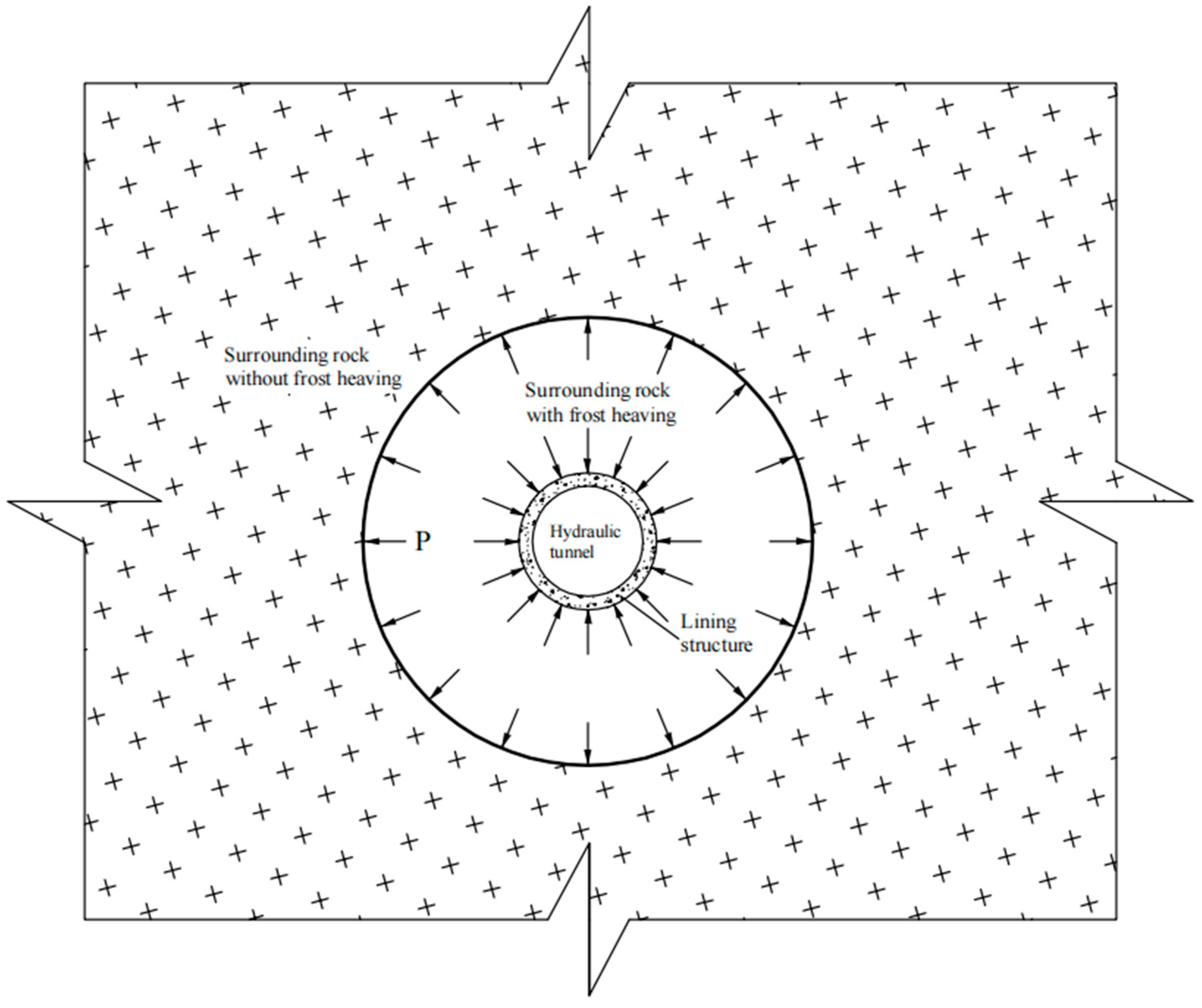
2. Establishment of Mechanical Model and Numerical Simulation Model

2.1. Constitutive Model of Support Structure

During tunnel construction in cold regions, concrete sprayed with antifreeze is usually used to provide the initial support for the tunnel. However, the supporting material may be damaged due to the low tensile strength during the process of low-temperature frost heave. In this scenario, the linear elastic model cannot accurately describe the failure process of concrete, resulting in a large error in numerical simulation results. The elastic-plastic model in the finite element software can accurately describe the change process of concrete from the elastic stage to the yield stage and then to the plastic stage according to the imported stress–strain relationship [19]. Therefore, the stress–strain curve of the concrete was determined through experiments, and the corresponding values of stress and strain were imported into finite software to construct an elastic-plastic constitutive model of the concrete support structure.

2.2. Basic Assumptions

The water–ice phase change produces expansion and generates frost heave force under the constraints of support and unfrozen surrounding rock, as shown in Figure 1.
The bearing safety analysis of tunnels is closely related to the freezing process of the surrounding rock mass. However, since the process of the low-temperature freezing of the rock mass involves the interaction of multiphase media, the microscopic change process is complex and difficult to simulate. This paper uses temperature field as the field variable to study the change of the stress field. The relevant assumptions in the study are as follows:
(1)
Both support structure and surrounding rock are composed of ideal materials with continuous, uniform, and isotropic characteristics.
(2)
The phase change occurs in a temperature range around Tm (Tm ± ΔΤ).
(3)
After two-dimensional plane analysis on tunnels in cold regions, the problem of the axial length of the tunnel much larger than the cross-sectional size can be regarded as a plane strain problem.
(4)
The porosity of the surrounding rock remains unchanged during the freezing process and the surrounding rock is always in a saturated state.

2.3. Temperature Field Control Equation

The frost heave problem of tunnels in cold regions is due to the freezing and expansion of in-situ pore water caused by the decrease in temperature in the tunnel during the freezing period. In addition, under the action of the temperature gradient, the water in the unfrozen area flows continuously to the frozen area through the seepage channel, resulting in a greater frost heave effect. The expansion of the surrounding rock in the frozen area is constrained by the support structure and the unfrozen surrounding rock, which will produce frost heave force. Therefore, the fundamental reasons for the frost heave of the rock surrounding the tunnels are the effect of low temperature, the water–ice phase change, and water migration in the rock mass. The temperature field equation considering the water–ice phase transition and water migration must be established to study the bearing safety of tunnels in cold regions.
According to reference [20], the control equation of the temperature field in the frozen area, considering the phase change of water–ice and water migration, can be expressed as:
C f T t + ρ w L f θ w t + ( λ f T n ) + [ ( ν w ) ( ρ w C w T ) ] = Q λ
where ρw and Cw are the density and specific heat capacity of water, respectively; vw is the seepage velocity of water; Lf is the latent heat of the water–ice phase change; θw is the volume fraction of water; and λf and Cf are the thermal conductivity and specific heat capacity of the rock mass in the frozen area, respectively. Qf is the heat generated or consumed by the control body due to heating or exothermic heat in the frozen area.
The control equation of the temperature field of the surrounding rock in the unfrozen and frozen areas is consistent with the structure of the frozen area, except that there is no latent heat term of phase change. Therefore, the control equation of the temperature field of the surrounding rock in the unfrozen area is:
C u T t + ( λ u T n ) + [ ( ν w ) ( ρ w C w T ) ] = Q u
where λu and Cu are the thermal conductivity and specific heat capacity of the rock mass in the unfrozen area, respectively. Qu is the heat generated or consumed by the control body due to heating or exothermic heat inside the unfrozen area.
In order to enhance the convergence of numerical calculation, Equation (1) can be rewritten as:
( C f + ρ w L f θ w t ) T t + ( λ f T n ) + [ ( ν w ) ( ρ w C w T ) ] = Q f
Equations (2) and (3) have the same form and can be combined as follows:
C e t T t + ( λ e t T n ) + [ ( ν w ) ( ρ w C w T ) ] = Q
where Cet is the apparent specific heat of surrounding rock; and λet is the apparent thermal conductivity of surrounding rock.
At present, the apparent heat capacity method is commonly used in the finite element analysis of geotechnical transformation problems [21]. According to the research on the initial freezing temperature of surrounding rock in reference [22], the initial freezing temperature is determined to be −3 °C, based on the porosity and salt content of the rock surrounding the tunnel. Considering the water–ice phase change inside the rock mass, according to the change of finite element parameters with temperature, the in-situ water below −3 °C is considered in a frozen state. The thermal conductivity and specific heat capacity of the rock mass are λu and Cu, respectively. The in-situ water with a temperature above 0.5 °C is in an unfrozen state, and the thermal conductivity and specific heat capacity of the rock mass are λf and Cf, respectively. When the temperature is between −3 °C and 0.5 °C, the in-situ water is considered in a freeze–thaw state and the expression for thermal conductivity is:
C e t = { C f , T < 3   ° C L f 2 Δ T + C f + C u 2 , 3   ° C C u , T > 0.5   ° C T 0.5   ° C
λ e t = { λ f , T < 3   ° C λ f + λ u λ f 2 Δ T [ T ( T m Δ T ) ] , 3   ° C T 0.5   ° C λ u , T > 0.5   ° C

2.4. Calculation Equation of Frost Heave Force of Frozen Rock Mass

When the temperature of the rock mass is lower than the freezing temperature, frost heave occurs, and the frost heave force is the extrusion force on the crack wall of the rock mass caused by the expansion of ice volume of the low-temperature crack water. Therefore, according to reference [23], Equation (7) is selected as the expression of the frost heave force of the frozen rock mass as follows:
P f = k i 1 k i K i T + ( a b 1 v s T 2 ) 1 G s T ( 1 + v s T )
where Pf is the frost heave force in the freezing process; ki = (1 + βuT)(1 − ζ) is the volume expansion coefficient of fissure water considering water migration; KiT = EiT/(1 − 2viT)/3 is the bulk modulus of fissure ice; EiT and νiT are the elastic modulus and Poisson’s ratio of ice at temperature T, respectively; a and b are the long and short axes of the fracture section, respectively; GsT = EsT/(1 − vsT)/2 is the shear modulus of the rock mass at temperature T; and EsT and vsT are the elastic modulus and Poisson’s ratio of the rock mass at temperature T, respectively.

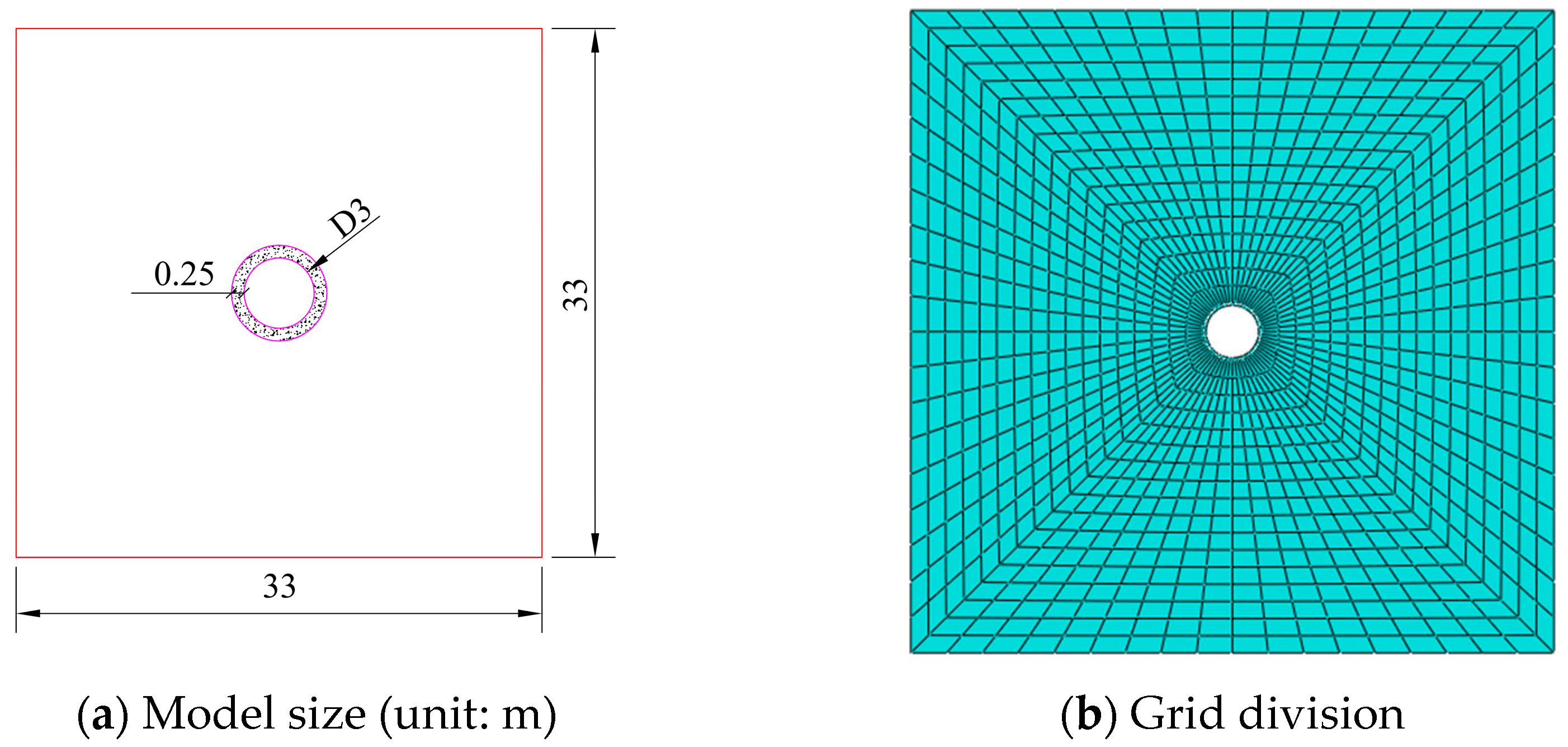
2.5. Establishment of Numerical Simulation Model

This paper relies on the mechanical model established in a previous paper and uses the actual engineering monitoring values as the reference variables. By adjusting the parameters, the finite element software is able to simulate the frost heave of the tunnel accurately. The stresses and plastic strains of the supporting structure are analyzed to determine the load-carrying safety of the supporting structure.
According to the analytical theory of Zheng Yingren et al. [24], it is known that taking a range of five times the cavern diameter around the circular tunnel can meet the practical problem of solving the stress and displacement analysis of the tunnel. Therefore, the calculation range of the surrounding rock is 33 m × 33 m, and the grid division of the model is shown in Figure 2. Zhang Yuwei et al. [25] studied the spatial and temporal distribution law of tunnel frost heave in cold regions based on the temperature field, and derived a formula for the calculation of the freezing depth in 2018. Based on this model and research results, the outer boundary of temperature field of the model in this paper was identified as the unfrozen constant temperature boundary, and its size was determined according to the ground temperature value of the buried depth of 20 °C. The inner boundary of the model temperature field was the gas–solid convection heat transfer boundary, the convective heat transfer coefficient was 39.96 W/(m2·°C), and the ambient temperature was taken from the temperature monitoring value inside the tunnel. According to assumption (4), the in-situ water in the surrounding rock was set to a saturated state. No seepage source was set because only the phase change of in-situ water was considered and the seepage was not considered. The model displacement boundary was set to be fully constrained at the bottom, the left and right boundaries were normal constraints, and the upper part was a free boundary. Load additions to the model included self-weight stress, pore stress, and pressure on the upper boundary from the upper surrounding rock.

3. Comparative Analysis of Engineering Measurement and Calculation Results

3.1. Project Overview

Permafrost and seasonally frozen soil are widely distributed in Xinjiang, and the frost heave problem of water conservancy projects in this region is more prominent.
The hydraulic tunnel of the hydropower station in Xinjiang is located at the edge of the ice and is in a mountainous area with structural erosion, which is a typical project for tunnels in cold regions. The excavation section of the hydraulic tunnel is circular, and the rock mass of the tunnel monitoring section is class IV surrounding rock with a burial depth of 156 m. Its compressive strength is 18.23 MPa, and its tensile strength is 1.81 MPa. Based on engineering data, indoor model test, and concrete design specification, the relevant parameters of the surrounding rock and support structure are shown in Table 1.
The measured values of frost heave during the low-temperature period of the hydraulic tunnel of this hydropower station are shown in Table 2.

3.2. Comparative Analysis

The volume expansion of the pore water in low-temperature rock mass produces the frost heave force that acts as a load on the support structure. Therefore, the frost heave force is the intuitive influencing factor of the frost heave effect on tunnel in cold regions on the bearing safety of the support structure. The effect of frost heave on the bearing safety of the support structure can be obtained from the change of the force of the support structure with the frost heave force.
In this paper, according to Yang Qing et al. [26], we used the method of subtracting the initial in-situ stress from the calculation result of the nodal stress to arrive at the frost heave force caused by the temperature drop of the frozen rock, thus obtaining the annular distribution of the frost heave force of the rock mass in the monitoring section through numerical calculation, as shown in Figure 3.
Comparing the simulated values with the measured values in Table 2, the errors of frost heave pressure at the top, waist, and bottom of the arch are 0.04 MPa, 0.06 MPa, and 0.07 MPa respectively. The overall error is small, which indicates that the accuracy of the simulation results of the numerical model established by using the mechanical model in this paper is good.
The numerical simulation results of the temperature field, displacement field, stress, and plastic zone of the monitoring section of the project are shown in Figure 4. Taking [−3 °C, 0.5 °C] as the freeze–thaw interval and the surface formed at −3 °C in the temperature field as the freezing front, the freezing depth of the rock mass can be obtained. The temperature field distribution of surrounding rock can then be obtained by inversion through the freezing depth. Whether the frost heave amount is similar to the measured value can be determined by the displacement field of the support structure to evaluate the accuracy of the model. The bearing safety of the support structure can be examined by comparing the stress and plastic strain obtained by taking the temperature field as a field variable with the allowable strength value and ultimate plastic strain.
A comparison of the measured results of the project and the numerical calculations shows the following.
(1)
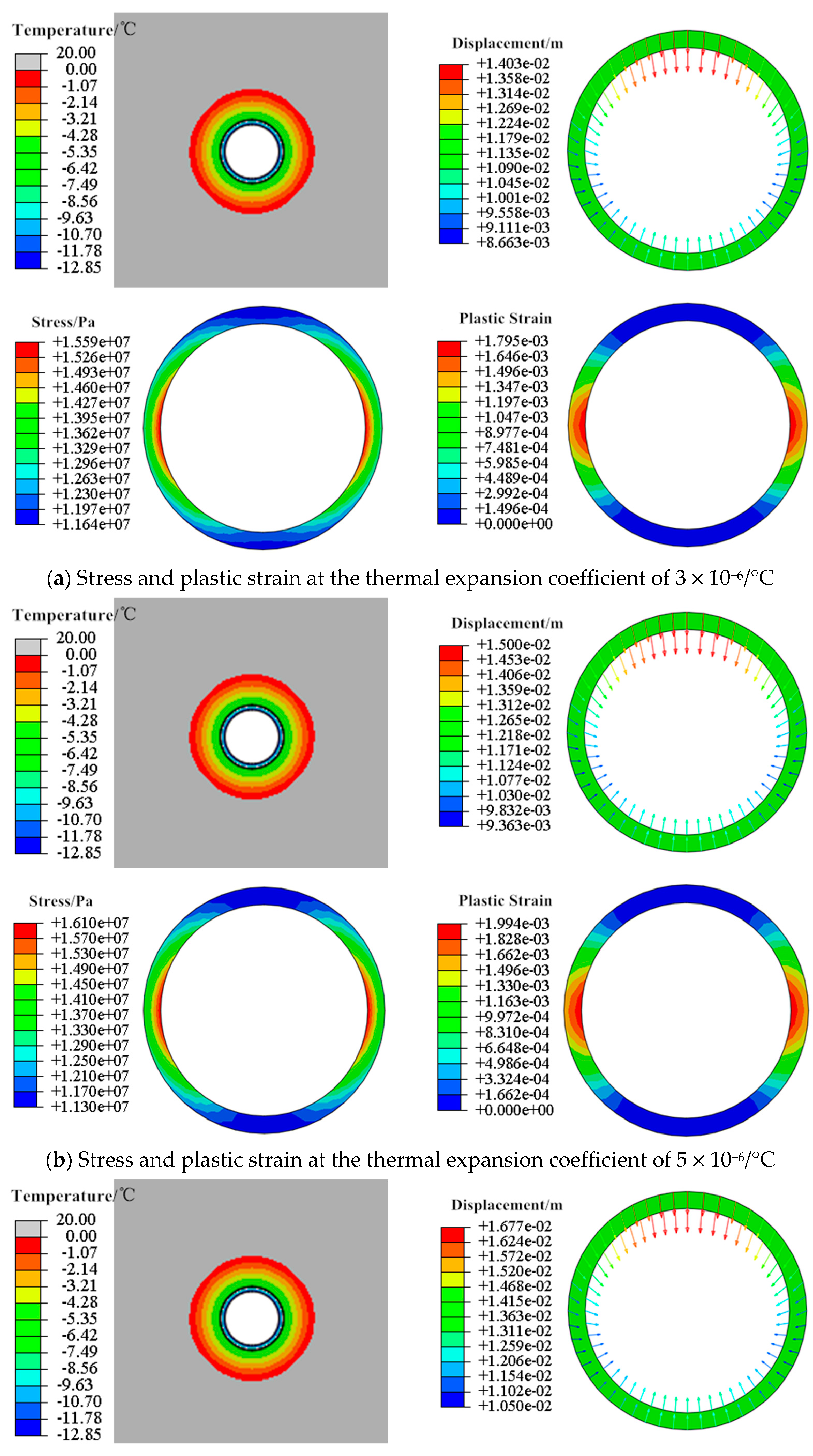
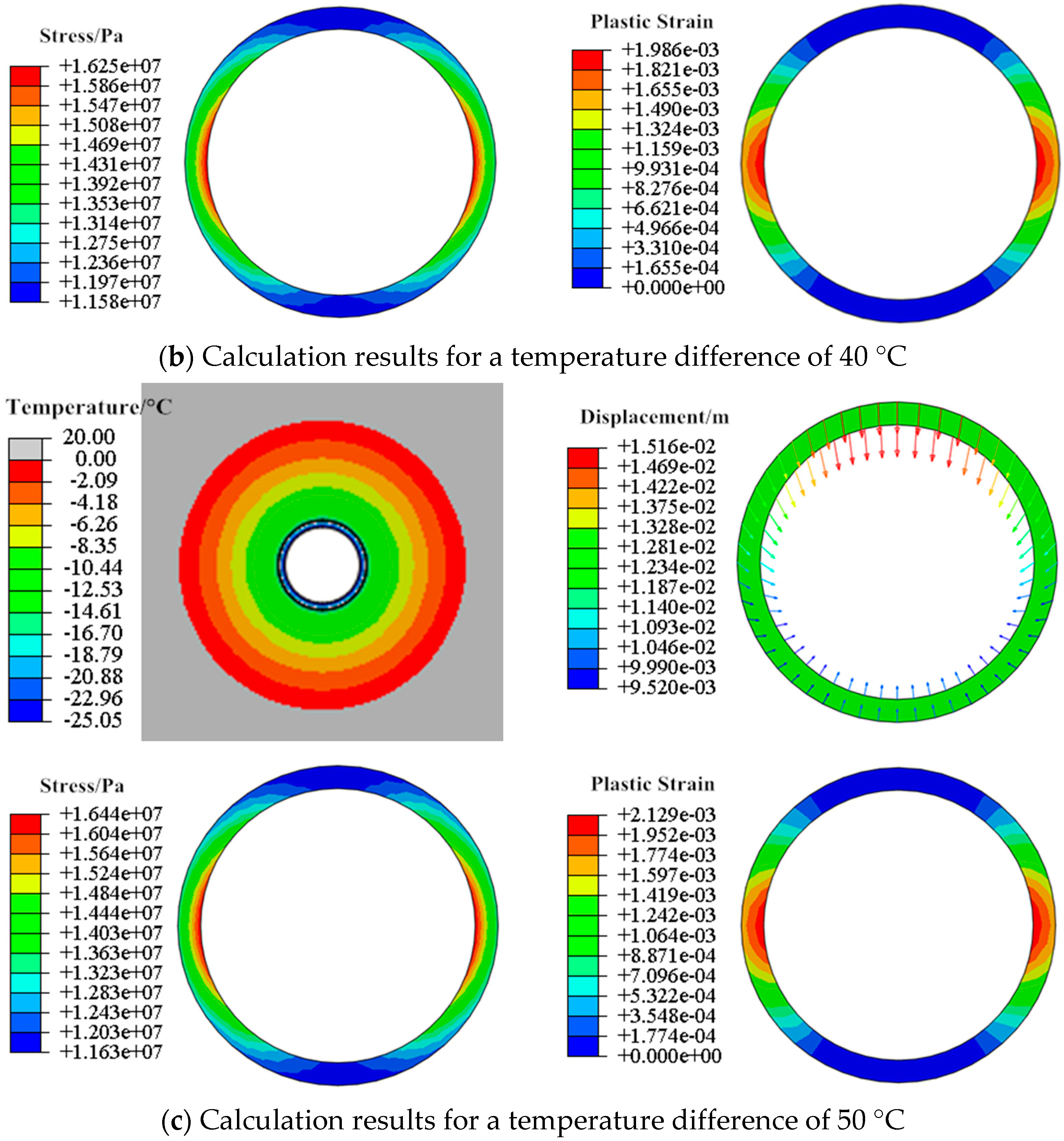
The freezing depth of the rock is 1.54 m. The temperature field of the rock is distributed in a circular pattern and the temperature become higher with greater distance from the cave wall. The freezing depth in the numerical simulation is consistent in all directions, while the measured freezing depth varies slightly in different directions. The maximum error between the numerical simulation and the measured freezing depth is 4.1% at the waist of the arch. This is mainly due to the fact that the surrounding rock and supporting structure are considered to be homogeneous in all directions in the numerical simulation. Conditions such as joints and seepage are not considered.
(2)
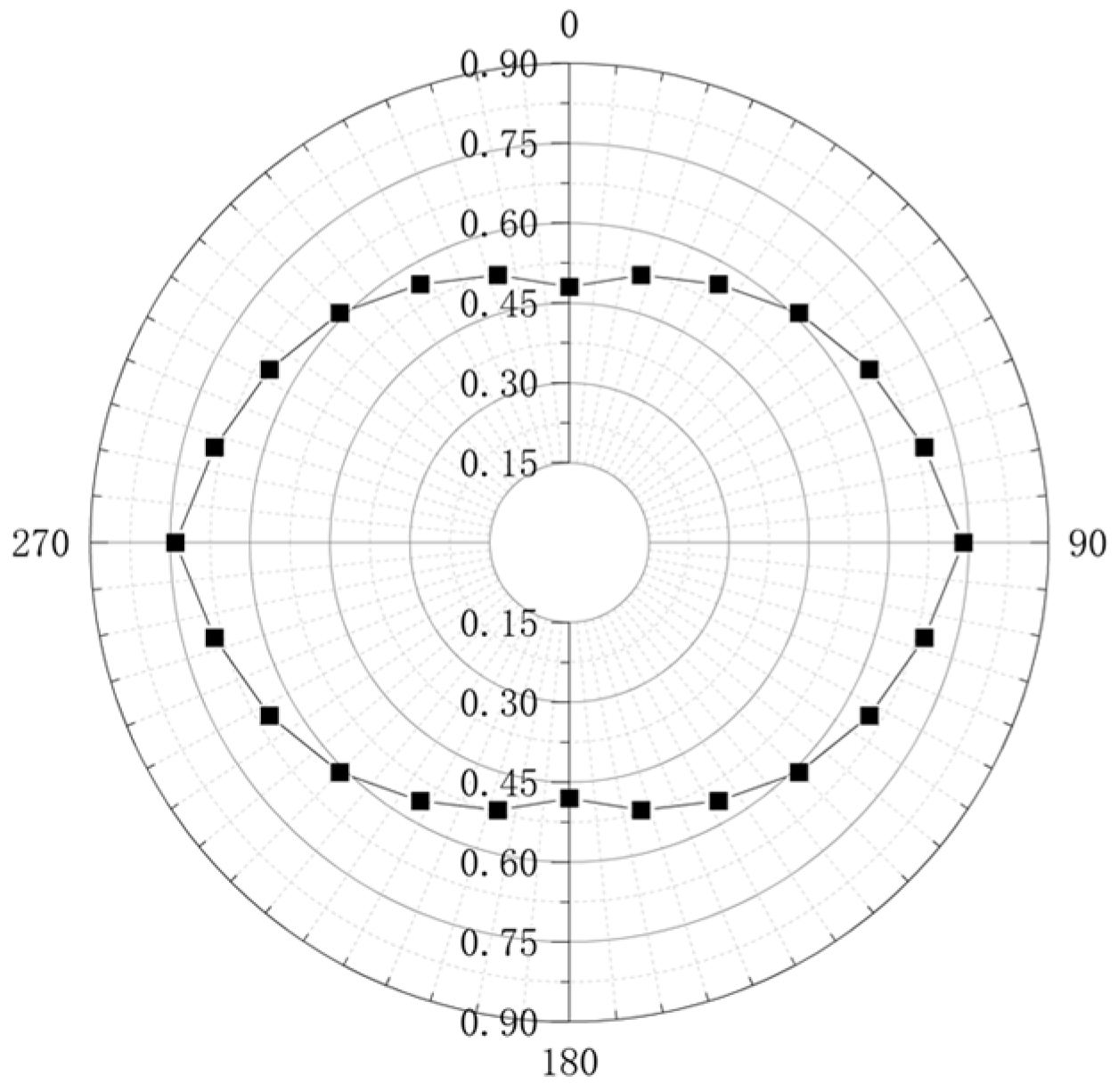
The displacement range of the support structure is 9.23~14.85 mm, which first decreases and then increases along the vault to the arch bottom. The frost heave at the vault is 14.85 mm, which is 10.8% higher than the measured value. The frost heave at the arch waist is 10.76 mm, which is 6.5% higher than the measured value. The frost heave at the arch bottom is 11.17 mm, which is 2.5% higher than the measured value. This is because the model assumes that the surrounding rock is always in a saturated state. The displacement value caused by the freezing and expansion of pore water inside the rock mass is larger than the measured value, but the overall error is controllable.
(3)
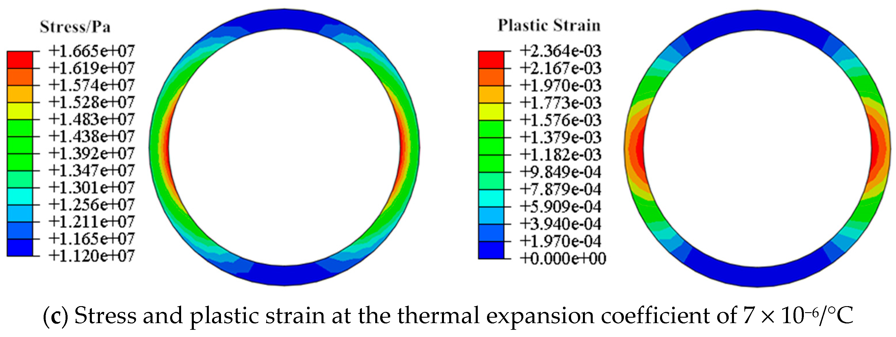
The stress of the support structure is all compressive stress in the range of 11.45~15.96 MPa. The stress first increases and then decreases from the vault to the arch bottom. The maximum compressive stress at the arch waist is 15.96 MPa, and does not reach the compressive strength of the support structure of 18.23 MPa. It can be seen from the cloud diagram of plastic strain that the arch waist section of the support structure enters a plastic state, and the maximum plastic strain is also at the arch waist, which is 1.976 × 10⁻³ and does not reach the ultimate plastic strain of 3.3 × 10⁻³.
Therefore, combined with the engineering measurement results and numerical calculation results, it can be judged that the tunnel supporting structure in this cold region has sufficient load-bearing capacity in this low-temperature section, and it can guarantee load-bearing safety before the secondary support. When assessing the safety of other similar cold region tunnel supporting structures, the mechanical model and numerical simulation model in this paper can be used and the reliability of the results obtained is high.

4. Analysis of Influencing Factors on Mechanical Characteristics of Support Structures

The thermal expansion coefficient, internal and external temperature difference, and surrounding rock porosity have important effects on the frost heave conditions of tunnels in cold regions and the bearing safety of support structures. The above-mentioned method for analyzing the bearing safety of support structures based on frost heave is used to analyze the influence of these three factors on the bearing characteristics of support structures under the effect of frost heave.

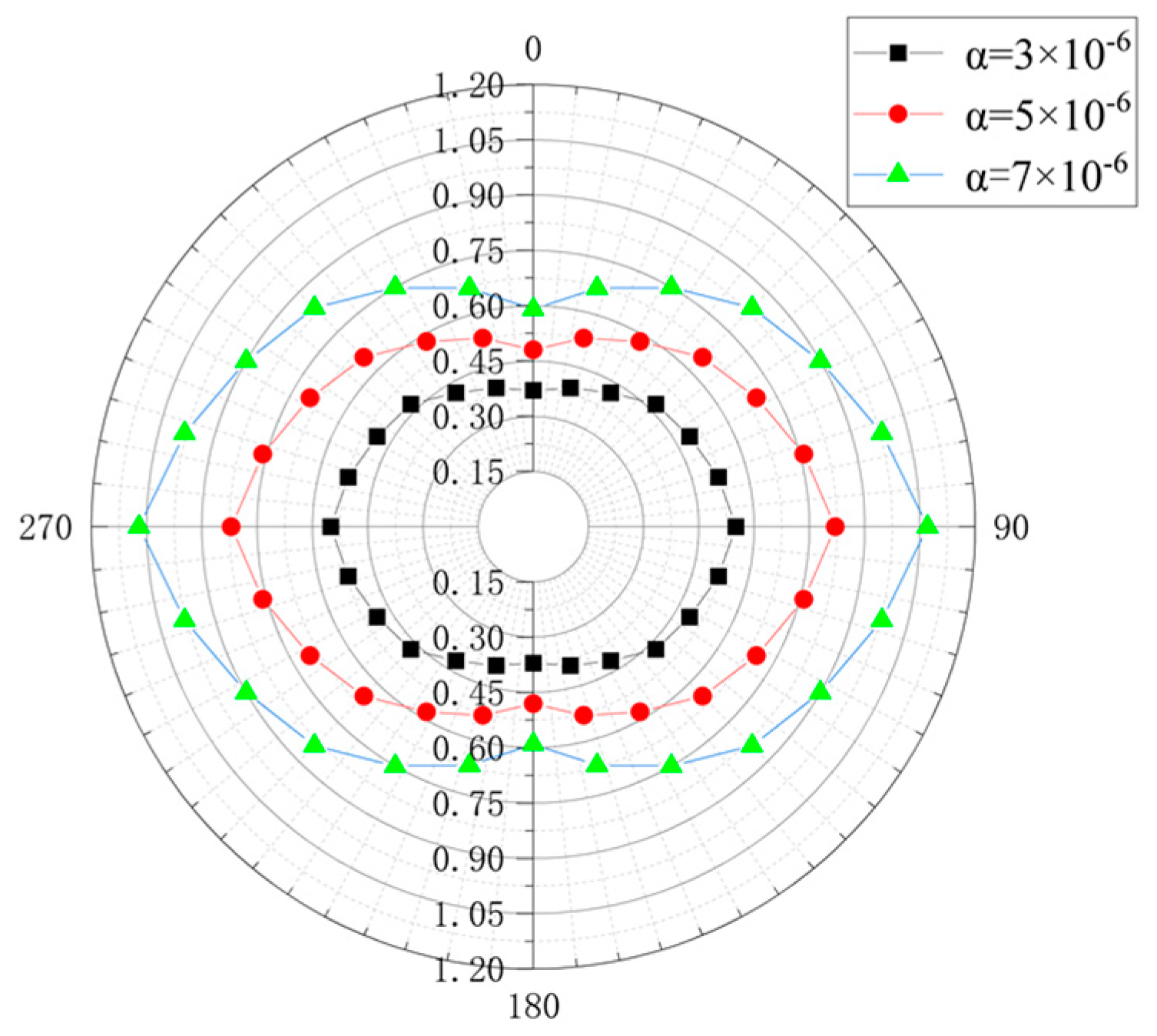
4.1. Influence of Thermal Expansion Coefficient on the Force of Support Structure

When the temperature field and other conditions were kept constant, the thermal expansion coefficient α was set to 3 × 10⁻⁶/°C, 5 × 10⁻⁶/°C, and 7 × 10⁻⁶/°C, respectively to obtain the annular distribution of the frost heave force of the rock mass using the single factor analysis method, as shown in Figure 5. The effect of changing the thermal expansion coefficient on the bearing characteristics of the support structure is shown in Figure 6.
From Figure 5 and Figure 6, when the temperature field is constant and the freezing depth does not change, the frost heave increases with the increase of the thermal expansion coefficient. It shows that the frost heave rate is proportional to the thermal expansion coefficient. The compressive stress at the arch waist of the support structure gradually increases from 15.59 MPa to 16.65 MPa with the increase of the thermal expansion coefficient. This result is consistent with the conclusion of the frost heave analysis of channel concrete lining studied by Wang Zhengzhong et al. [27]. The compressive stress at the vault and arch bottom decreases from 11.99 MPa and 11.24 MPa to 11.67 MPa and 11.71 MPa, respectively. This is because the increase of the thermal expansion coefficient leads to an increase in the expansion value of water freezing, and the frost heave force in all directions becomes greater. The extrusion effect in the vertical direction becomes more obvious, which is manifested as a larger displacement change at the arch bottom than that at the arch waist, leading to partial tensile stress at the vault and arch bottom to offset the compressive stress. The compression at the arch waist increases the compressive stress, making the compressive stress at the arch waist constantly approach the compressive strength value of the support structure. The plastic zone of the support structure does not extend significantly with the increase of the thermal expansion coefficient, but the plastic strain at the arch waist gradually increases. Therefore, it is considered that the increase of the thermal expansion coefficient leads to the increase of the frost heave force and thus reduces the bearing safety of the support structure.

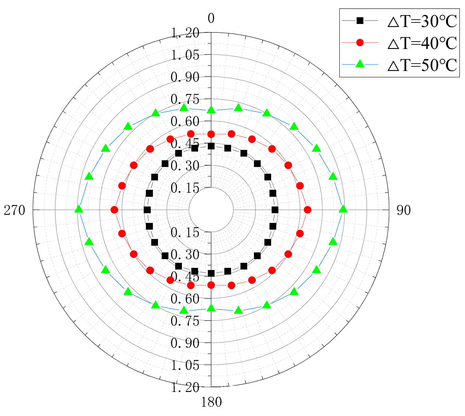
4.2. Influence of Temperature Difference on the Force of Support Structure

When the thermal expansion coefficient and other parameters were kept constant, we set the temperature in the tunnel to −10 °C, −20 °C, and −30 °C, and the internal temperature of surrounding rock at the buried depth to 20 °C, so the temperature difference ΔT between the inside and outside was 30 °C, 40 °C, and 50 °C, respectively. Then, the annular distribution of the frost heave force of the rock mass under different temperature differences was obtained by numerical calculation, as shown in Figure 7. The effect of changing the temperature difference on the mechanical characteristics of the support structure is shown in Figure 8.
From Figure 7 and Figure 8, it can be seen that the temperature difference of the rock mass changes the temperature field. As the temperature in the tunnel gradually decreases from −10 °C to −30 °C, the freezing depth of the rock mass increases from 0.73 m to 3.06 m, and the frost heave force also gradually increases from annular to elliptical distribution. The displacement of the support structure and the temperature difference are proportional. The displacement at the vault is the largest and gradually decreases along the annular direction, reaching the minimum at the arch waist, and then increasing to the arch bottom. The displacement range changes from 8.96~14.70 mm to 9.52~15.16 mm. The reason for the increase in the displacement is that the increase of the freezing depth leads to the increase of the expansion zone and the accumulated expansion caused by the water–ice phase transition. The stress of the support structure is proportional to the temperature difference, because the expansion area caused by the water–ice phase change increases with the increase of the freezing depth, and the compression in the vertical direction and the contraction in the horizontal direction of the support structure increase together with the self-weight and the lateral constraint of the model, resulting in the compressive stress of the support structure at each position along the annular direction increasing gradually. According to the changing law of plastic strain of the support structure, the maximum plastic strain value is proportional to the temperature difference. Therefore, the decrease in the temperature inside the tunnel leads to an increase in the freezing depth and the increase of frost heave force, which causes an increase in the overall stress of the support structure and has a negative impact on the bearing safety of the support structure.

4.3. Influence of Surrounding Rock Porosity on Supporting Structure Stress

Keeping other parameters such as the thermal expansion coefficient constant, the porosity n of the surfacing rock is set to 0.13, 0.23, and 0.33 respectively. Numerical calculations are carried out to obtain the annular distribution of frost heave pressure for different surfacing rock porosities, as shown in Figure 9. The effect of varying the porosity of the surfing rock on the force characteristics of the supporting structure is shown in Figure 10.
From Figure 9 and Figure 10, the variation law of the displacement of changing the initial porosity is consistent with that of changing the thermal expansion coefficient. However, the stress change of the support structure increases with the increase of porosity in the whole annular direction. This is because the rock mass is assumed to be always in a saturated state, and increasing the porosity is equivalent to increasing the water content of the rock mass. Under the same frozen domain, the higher the water content, the greater the expansion caused by the water–ice phase change, and the greater the frost heave force. This results in a greater force on the support structure, a greater overall displacement of the support structure, and a greater maximum plastic strain value of the rock mass, which is unfavorable to the bearing safety of the supporting structure.

5. Conclusions

This paper establishes a mechanical model considering frost heave, uses engineering measurements combined with numerical simulations, and analyzes the load-bearing safety of the supporting structure during the freezing period. The influence of different factors on the load-bearing characteristics of the supporting structure is also analyzed and the following conclusions are drawn.
(1)
The measured monthly average temperature of the project, −16.3 °C, is used for the numerical calculation. The results show that the maximum compressive stress of the supporting structure is located at the arch waist, which is 15.96 MPa. Although it does not exceed the compressive strength of the concrete, a plastic zone is created at the arch waist. Therefore, attention should be paid to strengthening the compressive measures at the arch waist during the secondary support construction to prevent the arch waist from cracking due to compressive deformation. The overall displacement trend of the supporting structure is inward contraction. The displacement of the top of the arch sinking is the largest, at 14.85 mm. The displacement of the bottom of the arch is in the middle of the range, at 11.17 mm. The shrinkage displacement of the arch waist is the smallest, at 10.76 mm. During the construction of the support, attention should be paid to strengthening the displacement control measures at the top of the arch.
(2)
After analyzing the coefficient of thermal expansion, temperature difference, and porosity of the surrounding rock, three factors affecting tunnel frost heave and force characteristics of cold regions can be obtained as follows. When other parameters are constant, the larger the thermal expansion coefficient, the larger the frost heave pressure of the rock mass, the larger the heave rate of the supporting structure, the larger the stress value and plastic strain at the haunch, and the more unfavorable the bearing safety. Moreover, a greater temperature difference leads directly to an increase in the freezing depth, meaning that the frost heave pressure also increases, and the displacement of the supporting structure gradually increases, leading to more unfavorable load-bearing safety. When the surrounding rock porosity is larger, the higher the water content of the rock mass, the greater the amount of expansion generated by the freezing, the greater the frost heave pressure, the greater the displacement and stress–strain value of the supporting structure, and the more unfavorable the bearing safety.
(3)
By increasing the strength of the supporting structure, actively or passively insulating the structure and installing effective drainage measures, the frost heave rate of the supporting structure can be reduced, the temperature difference reduced and the water content reduced, thus effectively enhancing the load-bearing safety of the supporting structure.
(4)
The accuracy of the simulation results of the numerical model established by using the mechanical model in this paper is good, and the agreement between the engineering measured results and the numerical calculation results is high. When assessing the safety of other tunnel supporting structures in similar cold regions, the mechanical model and numerical simulation model in this paper can be used.
This study provides a theoretical basis and reliable mechanical and numerical simulation model for establishing the bearing safety of tunnels in cold regions. In the future, it is necessary to change some important influence parameters and simulate more different working conditions for further analysis. According to the analysis results, efforts should be made to propose more reliable preventive measures to guide actual projects.

Author Contributions

Methodology, project administration and guidance, H.J.; data curation, editing, software and analysis, D.Z.; supervision and interpretation of data, K.S.; analysis, review and revision P.X. All authors have read and agreed to the published version of the manuscript.

Funding

This research was funded by the Regional innovation Guidance Plan project of the XPCC, grant number 2021BB004; the National Natural Science Foundation of China, Grant number 51769031; and the Science and technology plan project of Zhejiang Provincial Department of Water Resources, Grant number RB2213.

Data Availability Statement

Not applicable.

Conflicts of Interest

The authors declare no conflict of interest.

References

  1. Ma, X.L.; Dong, X.P. The frost damage mechanism and countermeasures for tunnels in cold regions. Chin. J. Undergr. Space Eng. 2014, 10, 1996–1999. [Google Scholar]
  2. Lv, K.C.; Ji, Z.; Ma, C.C.; Xu, P. Causes of tunnel frost damages in cold region and several new technologies to prevent them. Highway 2012, 57, 297–301. [Google Scholar]
  3. Liu, W.W.; Feng, Q.; Fu, S.G.; Wang, C.X. Elasto-plastic solution for cold-regional tunnels considering the compound effect of non-uniform frost heave, supporting strength and supporting time. Tunn. Undergr. Space Technol. 2018, 82, 293–302. [Google Scholar] [CrossRef]
  4. An, P.; Xing, Y.C.; Wang, S.H.; Cheng, D.W. Cause analysis of exfoliation of side walls for Karez tunnel and seepage control reinforcement. Trans. Chin. Soc. Agric. Eng. 2018, 34, 138–144. [Google Scholar]
  5. Jiang, H.B.; Zhai, D.S.; Xiang, P.F.; Wei, G. Research on frost heaving characteristics of hydraulic tunnels’ wall rock in cold regions based on phase transition and water-heat-stress coupling. Buildings 2022, 12, 1026. [Google Scholar] [CrossRef]
  6. Xu, P.; Zhang, J.H.; Zhang, D.B.; Xiao, C. Elastic-plastic analysis of stability of cold-region circular tunnels subjected to frost heaving force. China Saf. Sci. J. 2022, 32, 127–133. [Google Scholar]
  7. Li, Y. Research on the Anti-freeze Critical and Early Maturity of Negative Temperature Concrete in −10 °C Condition. Master’s Thesis, Shijiazhuang Tiedao University, Shijiazhuang, China, 2015. [Google Scholar]
  8. Dai, J.P.; Wang, Q.C.; Qu, S.; Duan, Y.; Xie, Z.G. Strength prediction model of low temperature curing concrete based on maturity theory. J. Mater. Sci. Eng. 2018, 36, 263–267. [Google Scholar]
  9. Li, W.; Zhang, D.M.; Ye, F.; Wang, S.Y.; Liang, X.M. Study on influence of freeze-thaw cycles on thermal conductivity of tunnel lining concrete in seasonal freezing zone. Tunn. Constr. 2020, 40, 1725–1732. [Google Scholar]
  10. Zhang, D.H.; Wang, M.S.; Tan, Z.S.; Kong, H.; Cui, J. Effect of frost heaving on tunnel surpporting systems of Fenghuoshan railway tunnel. Chin. J. Geotech. Eng. 2003, 25, 571–573. [Google Scholar]
  11. Feng, Q.; Fu, S.G.; Wang, C.X.; Liu, W.W.; Wang, Y.; Qiao, W.G. Analytical elasto-plastic solution for frost force of cold-region tunnels considering anisotropic frost heave in the surrounding rock. KSCE J. Civ. Eng. 2019, 23, 3831–3842. [Google Scholar] [CrossRef]
  12. Lv, Z.T.; Xia, C.C.; Wang, Y.S.; Luo, J. Analytical elasto-plastic solution of frost heaving force in cold region tunnels considering transversely isotropic frost heave of surrounding rock. Cold Reg. Sci. Technol. 2019, 163, 87–97. [Google Scholar] [CrossRef]
  13. Lv, Z.T.; Xia, C.C.; Liu, W.P. Analytical solution of frost heaving force and stress distribution in cold region tunnels under non-axisymmetric stress and transversely isotropic frost heave of surrounding rock. Cold Reg. Sci. Technol. 2020, 178, 103–117. [Google Scholar]
  14. Peng, X.L.; Wang, H.J.; Yang, F.C.; Jiang, H.B.; Li, C.C. Analysis of surrounding-rock frost-heaving characteristics of diversion tunnel in cold region: A case study on diversion tunnel project of Bulunkou hydropower station in Xinjiang. Tunn. Constr. 2021, 41, 232–239. [Google Scholar]
  15. Zeng, Y.; Hu, L.M. Calculation transformation and calibration of ABAQUS concrete plastic damage constitutive model. Water Resour. Power 2019, 37, 106–109. [Google Scholar]
  16. Qi, H.; Li, Y.G.; Lv, X.L. Study of variables of elastic plastic damage model and its engineering application. J. Zhejiang Univ. 2015, 49, 547–554+563. [Google Scholar]
  17. Yu, Q.Y.; Zhang, C.; Liu, C. Analysis and evaluation of secondary lining thickness detection and safety of high-speed railway tunnel. Subgrade Eng. 2019, 202, 214–217+227. [Google Scholar]
  18. Zhang, Y.W.; Li, Y.Y.; Xie, Y.L.; Zan, W.B. On frost-heave calculation model based on a broken freeze-thaw circle and its influential factors. Mod. Tunn. Technol. 2017, 54, 93–102. [Google Scholar]
  19. GB50010-2010; Code for Design of Concrete Structures. China Architecture & Building Press: Beijing, China, 2011.
  20. Tan, X.J. A Dissertation for the Doctoral Degree of geotechnical engineering in the Graduate School of Chinese Academy of Sciences. Doctor’s Thesis, Graduate School of Chinese Academy of Sciences, Wuhan, China, 2010. [Google Scholar]
  21. Bonacina, C.; Comini, G.; Fasano, A.; Primicerio, M. Numerical solution of phase change problems. Int. J. Heat Mass Transf. 1973, 16, 1825–1832. [Google Scholar] [CrossRef]
  22. Zhou, J.Z.; Wei, C.F.; Lai, Y.M.; Wei, H.Z.; Tian, H.H. Application of the generalized clapeyron equation to freezing point depression and unfrozen water content. Water Resour. Res. 2018, 54, 9412–9431. [Google Scholar] [CrossRef]
  23. Liu, Q.S.; Huang, S.B.; Kang, Y.S.; Pan, Y.; Cui, X.Z. Numerical and theoretical studies on frost heaving pressure in a single fracture of frozen rock mass under low temperature. Chin. J. Geotech. Eng. 2015, 37, 1572–1580. [Google Scholar]
  24. Zheng, Y.R.; Zhu, H.H. The Stability Analysis and Design Theory of Surrounding Rock of Underground Engineering, 1st ed.; China Communications Press: Beijing, China, 2012; pp. 120–146. [Google Scholar]
  25. Zhang, Y.W.; Xie, Y.L.; Li, Y.Y.; Lai, J.X. A frost heave model based on space-time distribution of temperature field in cold region tunnels. Rock Soil Mech. 2018, 39, 1625–1632. [Google Scholar]
  26. Yang, Q.; Rong, C.X. Distribution of the freezing temperature field and formation law of the frost heaving force of a deep expansive clay layer. J. Glaciol. Geocryol. 2020, 42, 878–888. [Google Scholar]
  27. Wang, Z.Z.; Zhang, C.Q.; Sha, J.D. A finite element analysis of the coaction between frozen ground and spread wall foundation. Acta Univ. Agric. Boreali Occident. 1998, 26, 12–17. [Google Scholar]
Figure 1. Schematic diagram of lining structure under frost expansion force.
Buildings 13 00544 g001
Figure 2. Numerical simulation model.
Buildings 13 00544 g002
Figure 3. Annular distribution of frost heave force of rock mass (unit: MPa).
Buildings 13 00544 g003
Figure 4. Numerical calculation results.
Buildings 13 00544 g004
Figure 5. Annular distribution of frost heave force of rock mass with different thermal expansion coefficients (unit: MPa).
Buildings 13 00544 g005
Figure 6. Influence of different thermal expansion coefficients on bearing characteristics.
Buildings 13 00544 g006aBuildings 13 00544 g006b
Figure 7. Annular distribution of frost heave force of rock mass with different temperature differences.
Buildings 13 00544 g007
Figure 8. Influence of different temperature differences on bearing characteristics.
Buildings 13 00544 g008aBuildings 13 00544 g008b
Figure 9. Annular distribution of the frost heave force of rock mass with different water content.
Buildings 13 00544 g009
Figure 10. Effect of different porosity on bearing characteristics.
Buildings 13 00544 g010aBuildings 13 00544 g010b
Table 1. Physical and mechanical parameters.
MaterialsDensity/(kg/m3)Elastic Modulus/GPaPoisson’s Ratio Thermal Conductivity/(w/(m·°C)Specific Heat Capacity/(J/(kg·°C)Cohesion/MPaInternal Friction Angle
/(°)
PorosityUltimate Plastic Strain
Support structure2400300.21.89603.1860.30.163.3 × 10−3
frozen rock215640.293.511500.61360.213 × 10−3
unfrozen rock21563.20.332.913500.68320.213 × 10−3
Table 2. Measured values of frost heave in the hydraulic tunnel.
SectionMonthly Average Temperature T/°CMaximum Freezing Depth/mFreeze Displacement ∆h/cmFrost Heave Rate η/%Frost Heave Force p/MPa
Vault−16.31.5613.48.590.44
Arch waist1.4810.16.820.68
Arch bottom1.5110.97.220.41
Disclaimer/Publisher’s Note: The statements, opinions and data contained in all publications are solely those of the individual author(s) and contributor(s) and not of MDPI and/or the editor(s). MDPI and/or the editor(s) disclaim responsibility for any injury to people or property resulting from any ideas, methods, instructions or products referred to in the content.

