Abstract
Innovative solutions for seismic-retrofitting existing structures are currently required, as often traditional strategies are expensive, non-reversible, highly invasive, and/or fail to address both serviceability and ultimate limit states together. The present paper describes a preliminary experimental campaign performed at TU Delft to investigate an innovative structural glass window for strengthening masonry buildings. To this purpose, a prototype composed of a timber frame, a semi-rigid adhesive, and a 20 mm thick structural glazing layer was designed. The prototype aimed to improve the structure’s behavior against minor but more frequent service vibrations (SLS), as well as against ultimate ones (ULS). Specifically, an increase in the structure’s in-plane capacity and stiffness was targeted to reduce cracking at low drifts/displacements, while at larger drifts, the adhesive’s tearing and timber crushing were used to activate damping. To evaluate the prototype’s performance, a quasi-static, cyclic, in-plane test on a strengthened full-scale wall was performed and compared with available data on a similar, yet unstrengthened, wall. Although the benefits were not pronounced in terms of cracking and energy dissipation, the implementation of the proposed strategy provided an increase in terms of initial stiffness (18%), force capacity (8%, 36%), and ductility (220%, 135%). This outcome provides the ground for numerical studies that will help better delineate the proposed strategy and improve the current design.
1. Introduction
In-plane vibrations of different intensity have shown the vulnerability of unreinforced masonry structures over the years and the current need for efficient strengthening techniques. For the case of Dutch buildings, this is especially relevant in the region of Groningen, where vibrations induced by anthropogenic activities have caused substantial damage to buildings. In this context, available intervention techniques currently in use for in-plane strengthening of masonry are ferrocement or shotcrete, externally bonded steel plates or frames, timber backing, composite strengthening systems, and even filling existing openings with masonry [1,2]. However, even if the techniques above can improve the behaviour of the structure, they are known to be expensive, non-reversible, highly invasive, and/or fail to address both serviceability and ultimate limit states together. Therefore, there is the need to develop and study innovative intervention techniques that are effective and relatively simple to be implemented.
The replacement of traditional windows by structural glass windows can be a potential quick-to-implement alternative that preserves the original aesthetics of the building and could also contribute to the improvement in the building’s energy efficiency. This technology could improve the masonry structures’ seismic performance, increasing their force capacity and lateral stiffness by utilising the window’s glass panel as a structural element. The increment in terms of stiffness should reduce displacements, and therefore, cracking at low seismic intensities. In addition, a supplementary energy dissipation source could be incorporated through the connection between the glass panel and the surrounding masonry that activates at higher intensities. De Groot [3] performed an exploratory computational study investigating the implementation of a window prototype composed of a timber frame, a semi-rigid adhesive, and a double-glazing unit having a structural layer of 20 mm in annealed glass. As a result, promising strengthening predictions were obtained on a masonry wall and terraced house made of solid clay bricks, i.e., an increment in the force capacity and a reduction in terms of expected damage. In particular, the computational study revealed that the strengthened wall reached 137% of the corresponding unstrengthened seismic force capacity, while the terraced house, with larger openings, reached 205%. Nevertheless, research and laboratory tests were needed to validate the aforementioned results and the applicability of this technology as a strengthening measure.
To this purpose, a follow-up study was performed at Delft University of Technology, designing a prototype of the window, and performing a quasi-static, in-plane test on a full-scale strengthened wall. The results obtained on the strengthened configuration were then compared with available data on a nominally identical unstrengthened wall similarly tested in previous studies [4,5]. The latter experimental study aimed to investigate and quantify the propagation of light damage induced by repeated low vibration levels, typical of the light earthquakes in Groningen (The Netherlands). This paper presents the materials and methods implemented, the results obtained, and the main conclusions drawn from this experimental study.
2. Materials and Methods
To assess the performance of a structural glass window against lateral loads, a window prototype was designed, and a quasi-static, cyclic, in-plane test on a full-scale strengthened wall was performed. Results obtained on the strengthened configuration were compared with available data on a nominally identical unstrengthened wall similarly tested in previous studies [4,5]
2.1. Description of the Window Prototype
The window prototype is reported in Figure 1 and was built with outside dimensions (length × height × thickness) of 730 × 1460 × 100 mm to fit into a window opening of dimensions 780 × 1510 mm. The gap of 25 mm circumferentially left between the window and the surrounding masonry is used to connect the window to the existing masonry. The window prototype mainly consists of a timber frame, a double-glazing unit with a 20 mm thick structural layer of annealed glass, and a semi-rigid adhesive.
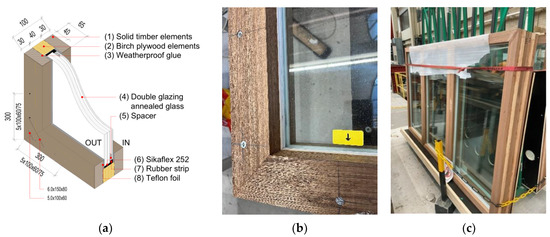
Figure 1.
Structural glass window prototype: (a) 3D view with components, (b,c) final product.
The timber frame is composed of outer parts in solid timber “Meranti” (1) with a cross-section of 30 × 65 mm, and a central part in birch plywood “Okoume” (2) with a cross-section of 40 × 40 mm. The plywood used had a characteristic class of F15/20 for strength and E35/40 for stiffness. Solid timber horizontal and vertical members are joined together in a miter joint using weatherproof wood glue for exterior use (3) and wood screws 5 × 150 mm and 5 × 100 mm. On the other hand, plywood elements are joined in a basic joint using only the same glue. The central part of the frame is fastened to the external parts using, in addition to the same glue, wood screws 5 × 100 mm.
The double-glazing system (4) comprises two, 10 mm thick annealed glass panes laminated together with dimensions (length × height) of 640 × 1370 mm, and one 4 mm single panel with dimensions (length × height) of 620 × 1350 mm. The 10.10 mm and 4 mm thick glass panels are spaced by a 4 mm thick acrylic spacer (5) to promote the thermal and moisture seal.
The connection between the 10.10 mm thick glass panel and the central part of the timber frame in plywood is made by a 5 mm thick polyurethane adhesive layer in Sikaflex-252 (6) that extends circumferentially over the entire depth of the glass panel (20 mm). The adhesive should also accommodate natural deformations of the structure due to seasonal temperature changes. Information about the structural properties of the adhesive is reported by Huveners [6]. A 10 mm thick rubber strip (7) is used to fill the space between the central part of the timber frame and the 4 mm glass panel and avoid any load transfer to the latter. In addition, 5 mm Teflon foils (8) are placed between the glass panels and the timber frame to guarantee a low friction contact surface on the faces of the glass.
The construction of the window prototype was performed at TU Delft Macrolab/Stevin laboratory following the procedure reported in Figure 2.
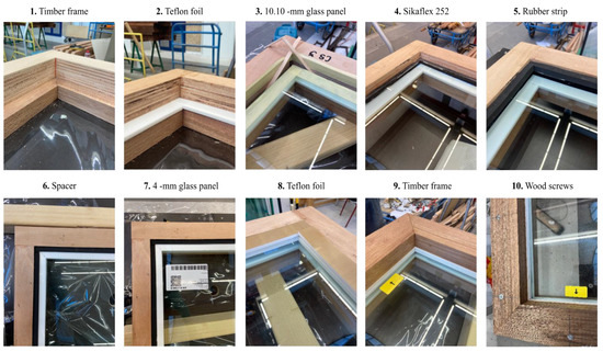
Figure 2.
Overview of the structural glass window construction.
To understand the behaviour of the window prototype and evaluate its capacity, a quasi-static in-plane test on the standalone prototype was performed (Figure 3a). During the test, the window was loaded in a double clamp configuration by imposing a displacement at its bottom right corner while its top part remained fixed. The resulting capacity curve (Figure 3b), expressed as horizontal in-plane load vs. horizontal drift, showed elasto-plastic behaviour that can be divided into three subsequent phases as follows. In the first stage, the load was transferred through the adhesive without tearing, leading to a linear elastic behaviour of the window. The linear elastic stage is depicted in green and is followed by a second stage in which tearing of the adhesive occurs. Tearing of the adhesive started at a drift of 1.9% and concluded at 3.3% when direct contact between the glass panel and the wooden frame occurred after crushing of the adhesive. During the last phase, the glass panel rotated inside the wooden frame compressing and deforming the horizontal plywood elements. At the end of the test, these plywood elements showed residual plastic deformation with a glass penetration of around 10 mm.
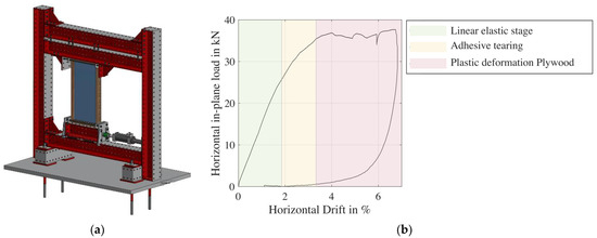
Figure 3.
In-plane test on the standalone window: (a) test set-up, (b) obtained capacity curve.
2.2. Description of the Wall Specimens
The specimen consisted of a full-scale single-wythe (100 mm thick) masonry wall with an asymmetric window opening in which the herein exposed prototype was installed (Figure 4a). In addition to the latter, a nominally identical unstrengthened masonry wall (Figure 4b), tested in previous studies under the same configuration and with similar loading protocol but without the structural glass window in the opening, was considered to evaluate the performance of the strengthening measure. While the strengthened wall, herein denoted TUD-COMP56, was built and tested in 2022, the unstrengthened wall, denoted TUD-COMP41, was built in 2017 and tested in 2017 and 2018 by Korswagen et al. [4,5]; Table 1 lists the material properties obtained in the construction period of both walls. The geometry and type of masonry considered aimed to replicate typical Dutch houses of the period before 1950 in the Netherlands. In particular, the walls were built in running bond using solid clay bricks and a 1:2:9 (cement: lime: sand proportions by volume) mortar [7]. The masonry units had a nominal dimension (length × height × thickness) of 210 × 50 × 100 mm and compressive strength of 28.31 MPa [8], experimentally determined accordingly to EN 772-1 [9]. The specimens had a 10 mm mortar joint and were built in controlled laboratory conditions by a professional bricklayer. Each wall was constructed on a steel beam by gluing the first masonry course with “Sikadur 30”. After construction and a hardening period, a steel beam was glued on top of the last masonry course with the same glue and was connected to the bottom beam via lateral steel columns and bars. This steel frame was used to transport the wall into the set-up and, via the top beam, apply the desired pre-compression and lateral force during the test.
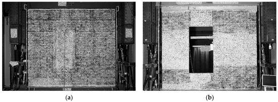
Figure 4.
Front view of the in-plane walls with the DIC black-and-white pattern applied: (a) strengthened (TUD-COMP56) and (b) unstrengthened (TUD-COMP41) specimen where the glass and timber frame are also painted.

Table 1.
Overview of masonry properties.
In the case of the strengthened wall, the prototype was installed once the wall was settled inside the set-up and the overburden was applied. In particular, the window was connected mechanically to the surrounding masonry using the connection solution shown in Figure 5. The mechanical connection was localized at the corners where maximum stresses are concentrated. It mainly consisted of groove mounting plates, fixed to the window’s wooden frame with wooden screws 4 × 40 mm, and sleeve anchors with a diameter of 8 mm and a length of 80 mm, installed in the masonry previously pre-drilled at the specified locations. In this manner, the window was slid into the opening. The gap left between the window and the surrounding masonry was then filled with SikaGrout-312.
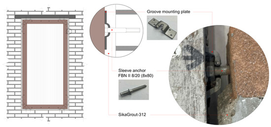
Figure 5.
Window installation. The window is mechanically anchored to the masonry and concrete lintel and its perimeter is filled with grout.
2.3. Test Set-Up, Instrumentation and Loading Scheme
The set-up adopted for lateral loading of both full-scale walls is shown in Figure 6. It consists of a steel frame, anchored at the stiff laboratory floor, in which the wall is settled. In particular, the bottom steel beam on which the specimen is built is connected to the bottom cross-beams of the steel frame to prevent uplift. Instead, the top beam, glued after construction to the last masonry course, is connected to a 100-kN hydraulic jack to induce the prescribed horizontal displacement to the specimen. The weight of the top beams results in a constant overburden of 0.12 MPa that mimics the load of ground-floor walls of typical two-story Dutch houses. The test is performed in a cantilever configuration, with the top beam free to displace and rotate in plane. During the test, the wall was monitored through digital image correlation (DIC) on the front side and sensors on the back side.
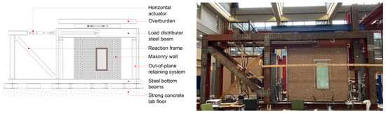
Figure 6.
In-plane test set-up looking at the back of the wall (without DIC pattern).
The walls were tested under a displacement-controlled procedure following a cyclically increased loading protocol (Figure 7). The protocol comprised a first part up to the serviceability limit state (SLS), and a second part up to ultimate limit states (ULS). The SLS part of the protocol was defined by Korswagen et al. [4,5,10] to investigate the initialization and propagation of cracks induced by repeated low vibration levels, typical of the light earthquakes in Groningen (The Netherlands). The ULS part of the protocol was representative of an expected Groningen-type earthquake and was derived by Mariani [11]. The SLS part consisted of a first repetitive part with 5 incremental steps and a subsequent (two-way) cyclic part with 7 incremental steps. For the two walls, the repetitive part of the SLS protocol was slightly different in terms of the number of repetitions per displacement step that were implemented: while, in the strengthened wall, 30 repetitions with the same loading rate (0.125 mm/s) were applied, in the unstrengthened wall, 20 repetitions were applied with two different loading rates (the first 10 repetitions at 0.0125 mm/s and the last 10 at 0.125 mm/s).
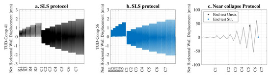
Figure 7.
Loading protocol: (a) SLS part unstrengthened wall; (b) SLS part strengthened wall; (c) ULS part for both walls.
3. Results
In this section, the results obtained in terms of base shear force versus net horizontal displacement of the wall, final cumulative crack pattern, deformed shape, and failure mechanism for the unstrengthened (Figure 8, Figure 9 and Figure 10) and strengthened (Figure 11, Figure 12 and Figure 13) walls are presented. The net horizontal displacement of the wall was calculated as the displacement of the top beam with respect to the external reference excluding possible rotations of the set-up.
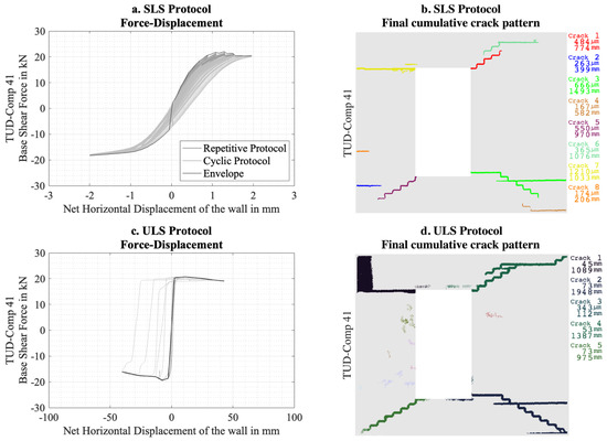
Figure 8.
Results obtained on the unstrengthened wall (TUD-Comp41) in terms of base shear force versus net horizontal displacement curve and final cumulative crack pattern for the SLS and ULS protocol.
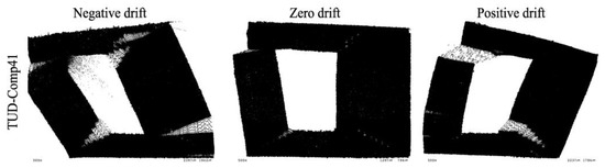
Figure 9.
Deformed shape, magnified 500 times, of the unstrengthened wall (TUD-Comp41) resulting from the SLS protocol at a displacement of 2.125 mm (0.085% drift) [5].
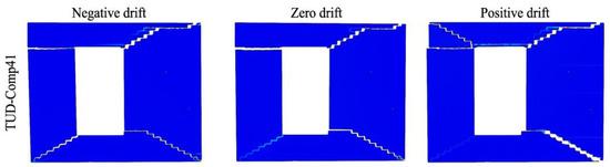
Figure 10.
Failure mechanism of the unstrengthened wall (TUD-Comp41) resulting from the ULS protocol at a displacement of 40 mm (1.6/−1.5% drift).
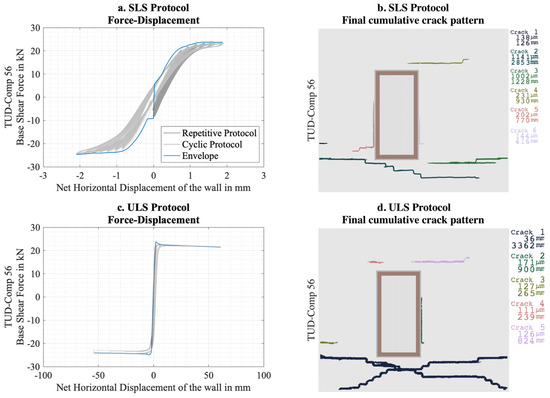
Figure 11.
Results obtained on the strengthened wall (TUD-Comp56) in terms of base shear force versus net horizontal displacement curve and final cumulative crack pattern for the SLS and ULS protocol.
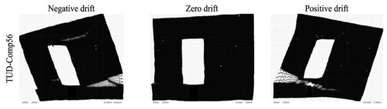
Figure 12.
Deformed shape plots (500 times magnified) of the strengthened wall (TUD-Comp56) resulting from the SLS protocol at a displacement of 2.125 mm (0.085% drift).
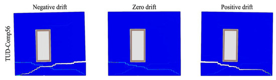
Figure 13.
Failure mechanism of the strengthened wall (TUD-Comp56) resulting from the ULS protocol at a displacement of 60 mm (2.3/−2.0%).
Considering the unstrengthened case, a maximum base shear force of +22.1 kN (at 1.28 mm displacement, 0.05% drift) and −19.5 kN (at −7.0 mm displacement, 0.26% drift) was obtained, with an initial stiffness of 37.6 kN/mm, evaluated in the first repetition of the protocol at 40% of the maximum force (8.3 kN). The ultimate displacement, evaluated at a residual capacity of 80%, was 40 mm (1.6/−1.5% drift). No significant out-of-plane displacements were reached during the test as the maximum displacement was 8 mm (8% of the wall thickness). The onset of cracking occurred at the first repetition of the protocol with the horizontal crack at the bottom left side of the short pier (Crack 2 in Figure 8b) and at the top left corner of the window opening (Crack 7 in Figure 8b). The evolution of the crack pattern resulted mainly in diagonal cracks from the window corners, causing a rocking behavior of the piers and sliding of the masonry portion above the window opening and the larger pier with respect to the rest (Figure 10).
Considering the strengthened case, a maximum base shear force of +23.9 kN (at 1.58 mm displacement, 0.06% drift) and −25 kN (−3.9 mm displacement, 0.14% drift) was obtained, with an initial stiffness of 44.6 kN/mm, evaluated in the first repetition of the protocol at 40% of the maximum force (9.6 kN). The onset of cracking occurred at the first repetition of the protocol with the two horizontal cracks at the bottom left side of the pier of lower length (Crack 1 and Crack 2 in Figure 11b). The evolution of the crack pattern resulted in two diagonal cracks at the masonry portion below the window opening. The latter cracks grew through the entire length of the wall, leading to rocking of the masonry portion above the aforementioned cracks as a whole piece (Figure 13). The test was stopped before reaching the ultimate displacement when the complete rocking mechanism was confirmed, i.e., at approximately 60 mm (corresponding to a drift of 2.3/−2.0%) and a residual capacity of 90% and 96%, respectively, in the positive and negative directions. Although leading to an underestimation of the ultimate displacement, the latter position is herein considered as the ultimate to allow future investigations of the specimen in a different boundary condition that might better force the glass panel to activate. In fact, with the presented cantilever configuration, no contact between the glass panel and timber frame was observed during the test: the maximum relative displacement, measured from the DIC at the end of the test, was −0.4 mm in both loading directions. The window remained in the linear elastic stage (Figure 3b) for the entire duration of the test: maximum wall drift in the first and second stages of the protocol was 0.1% and 2%, respectively. Regarding the out-of-plane deformation, the maximum out-of-plane displacement of the wall was 7 mm (7% of the wall thickness), which is low and comparable to the unstrengthened solution. This suggests that the asymmetrical placement of the structural glass in the thickness of the wall did not affect the out-of-plane deformation of the wall.
4. Discussion
The performance of the unstrengthened and the strengthened wall under the SLS and ULS protocol are compared in this section. The comparison is made in terms of initial stiffness, crack width, crack length, and the damage parameter Psi (Ψ) defined by Korswagen et al. [4,5,12] for the SLS protocol, while for the near collapse protocol, it is made in terms of the bilinear curve and failure mechanism which include strength, hysteresis and ductility. The Psi (Ψ) parameter, estimated from the properties of the cracks (number, width, and length), was considered to quantify the intensity of the (aggravation of the) damage reached at the end of the SLS protocol.
Figure 14 shows the comparison in terms of crack width and length obtained from the final cumulative crack pattern of the first stage of the protocol. In comparison with the unstrengthened wall, the strengthened configuration showed a lower number of cracks overall, with lower width but higher length. The damage was mainly concentrated in the masonry portion below the window opening, while it was more spread in the unstrengthened wall. Although an increment of 18% of the initial stiffness was observed in the strengthened configuration, no influence of the structural glass window was observed regarding the onset of cracking and final damage level reached from the first stage of the protocol. In fact, the first cracks appeared at the first repetition of the protocol in both cases considered herein, and a similar damage parameter Psi (Ψ) of 2.6 was computed. However, the increased stiffness would likely lead to a smaller displacement if the wall was subjected to seismic vibrations at its base; however, this depends on the dynamic behaviour of the wall and its interaction with the vibrations, and needs to be investigated further.
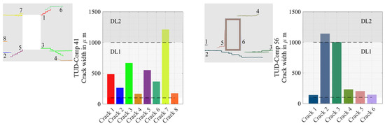
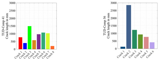
Figure 14.
Performance during the SLS phase in terms of crack width and length.
Figure 15a shows the equivalent bilinear curve computed according to the formulation of Magenes et al. [13] with the parameters listed in Table 2, while Figure 15b shows the contour plot to visualize the amount of energy released during the test, i.e., the enclosed area. By comparing the equivalent bilinear curves, a substantial increment in terms of stiffness (+142%, +136%), ultimate displacement (+43%, +35%), maximum base shear force (+8%, +36%), and ductility (+220%, +135%) was obtained in the strengthened configuration. However, the latter showed a substantial decrease in terms of dissipated energy (−83%) that can probably be attributed to the different failure mechanisms observed. In fact, while the strengthened wall showed only rocking, the unstrengthened one also showed sliding. In addition, the horizontal displacements reached during the tests were not sufficient for the adhesive to tear, and, therefore, for including the additional dissipation source through friction and crushing of the timber.
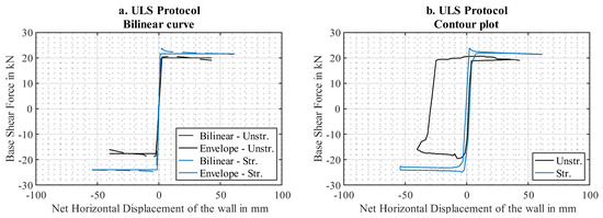
Figure 15.
Performance during the ULS protocol: (a) equivalent bilinear curve and (b) contour plot.
Table 2.
Overview of the parameters of the bilinear curve.
The change in failure mechanism to rocking cracks at the bottom, which is characteristic of walls without openings in a cantilever configuration, suggests that the window prototype forced the wall to behave as a whole as if no opening was present. The installation procedure was therefore successfully implemented to connect the proposed strengthening technique to the surrounding masonry. In windows with larger openings or with floor-to-ceiling openings, the strengthening window would likely provide larger gains in terms of improved stiffness and energy dissipation.
A numerical study supported by the presented experimental campaign will be employed to explore how the prototype’s design can be upgraded to overcome the aforementioned drawbacks. In particular, the numerical models will investigate whether the window’s plastic behaviour (Figure 3b) can be activated for lower lateral displacements to master the lack of dissipated energy obtained with the proposed wall’s geometry. Factors influencing the window’s plastic behaviour will, therefore, be analysed: adhesive thickness and mechanical properties (stiffness and strength) of the adhesive and plywood. On the other hand, variations in the wall’s geometry will be also considered to quantify the amount of energy dissipated considering different window sizes. In fact, in geometries with a larger opening, a higher wall’s deformation might be expected, which could activate the plastic phase of the window for lower lateral displacements. Regardless of the model considered during the prototype’s optimization phase, the effect on the initial stiffness, the cracking pattern, and the damage parameter Psi (Ψ) will also be monitored. The numerical study, with prior experimental validation, will allow the delineation of the proposed strengthening strategy and initiate the drafting phase of design guidelines for masonry systems vulnerable to in-plane actions. It must be pointed out that the proposed technique is intended for unreinforced masonry buildings vulnerable to in-plane failure and might not be beneficial for elements in which failure is governed by out-of-plane actions, as might be the case for masonry infills within reinforced concrete frames.
5. Conclusions
The development of innovative techniques for retrofitting masonry structures is becoming more and more of interest, with masonry being well-known for its seismic vulnerability and the available techniques for their high invasiveness. In this context, the applicability of an innovative window that utilizes glass as a structural element might represent a possible strengthening candidate. As exposed in an exploratory computational study [3], implementing such technology can increase the force capacity and reduce the expected damage of the existing masonry. However, no experimental work that validates the latter results and the potentiality of the technique was available.
To this purpose, a follow-up study was performed at Delft University of Technology designing a prototype of the window, evaluating its behavior through a quasi-static in-plane test on the standalone prototype, and performing a quasi-static in-plane test on a full-scale strengthened wall. Results obtained were compared with available data on a nominally identical unstrengthened wall similarly tested in previous studies [4,5]. The following conclusions can be drawn.
Implementing the structural window resulted in an increment in the initial stiffness (+18%) and a modification in the cracking phenomenon that appeared less spread and more concentrated to the masonry portion below the window opening. However, no influence on the final damage level was observed (with a Psi (Ψ) parameter equal to 2.6 in both cases). In fact, even if cracks appeared less in number and width, a significant increment in crack length was observed. Nevertheless, in dynamic situations, cracking is expected to reduce because of the higher stiffness.
The performance of the strengthened wall under the ULS protocol showed an overall improvement with respect to the unstrengthened configuration. In particular, an increment in terms of stiffness (+142%, +136%), ultimate displacement (+43%, +35%), maximum base shear force (+8%, +36%), and ductility (+220%, +135%) was observed. However, the design of the prototype should be revisited to better include an additional energy dissipation source. In fact, a substantial decrease in terms of dissipated energy (−83%) was observed due to the different failure mechanism, i.e., the lack of sliding in the case of the strengthened configuration, and the absence of deformation in the adhesive between the glass and timber frame.
The presented study only provides an insight into the potential of the exposed technique, since it is based on a limited number of tests. Further experiments will be conducted to deeply investigate the proposed prototype by testing the exposed strengthened wall in a different boundary condition that might better force the glass panel to activate. The complete experimental campaign will support the validation of numerical models that will be used to improve the window prototype and the strengthening strategy proposed.
Author Contributions
Conceptualization, M.B.G. and P.A.K.; methodology, M.B.G. and P.A.K.; Formal analysis, M.B.G. and P.A.K.; investigation, M.B.G.; writing—original draft preparation, M.B.G.; writing—review and editing, P.A.K., R.E. and J.G.R.; visualization, M.B.G.; supervision, P.A.K., R.E. and J.G.R.; funding acquisition, J.G.R. All authors have read and agreed to the published version of the manuscript.
Funding
This research was funded by Topsectoren en Topconsortia voor Kennis en Innovatie (TKI) in connection with research for Nederlandse Aardolie Maatschappij (NAM).
Data Availability Statement
The data that support the findings of this study are available in 4TU.RESEARCHDATA at http://doi.org/10.4121/20904511.
Acknowledgments
The authors are thankful to the staff of the TU Delft Macrolab/Stevinlaboratory for the support in designing and performing the laboratory experiments.
Conflicts of Interest
The authors declare no conflict of interest. The funders had no role in the design of the study; in the collection, analyses, or interpretation of data; in the writing of the manuscript; or in the decision to publish the results.
References
- Wang, C.; Sarhosis, V.; Nikitas, N. Strengthening/retrofitting techniques on unreinforced masonry structure/element subjected to seismic loads: A literature review. Open Constr. Build. Technol. J. 2018, 12, 251–268. [Google Scholar] [CrossRef]
- ElGawady, M.; Lestuzzi, P.; Badoux, M. A review of conventional seismic retrofitting techniques for URM. In Proceedings of the 13th International Brick and Block Masonry Conference, Amsterdam, The Netherlands, 4–7 July 2004; pp. 1–10. [Google Scholar]
- De Groot, A. Structural Window Design for in-Plane Seismic Strengthening. Master’s Thesis, TU Delft, Delft, The Netherlands, 2019. Available online: https://repository.tudelft.nl/islandora/object/uuid%3Ac87367bf-54ae-4bdb-898f-5bf9c7555c55?collection=education (accessed on 1 July 2022).
- Korswagen, P.; Longo, M.; Meulman, E. Damage Sensitivity of Groningen Masonry Structures–Experimental and Computational Studies, Stream 1; Report No. C31B69WP0-12; Delft University of Technology: Delft, The Netherlands, 2017. [Google Scholar]
- Korswagen, P.; Longo, M.; Meulman, E. Damage Sensitivity of Groningen Masonry structures–Experimental and Computational Studies, Stream 2; Report No. C31B69WP0-13; Delft University of Technology: Delft, The Netherlands, 2019. [Google Scholar]
- Huveners, E.M.P. Circumferentially Adhesive Bonded Glass Panes for Bracing Steel Frame in Façades; Technical Report; Tecnische Universiteit Eindhoven: Eindhoven, The Netherlands, 2009. [Google Scholar]
- Jafari, S. Material Characterisation of Existing Masonry: A Strategy to Determine Strength, Stiffness and Toughness Properties for Structural Analysis. Ph.D. Thesis, Delft University of Technology, Delft, The Netherlands, 24 September 2021. [Google Scholar] [CrossRef]
- Jafari, S.; Esposito, R. Material Tests for the Characterisation of Replicated Solid Clay Brick Masonry; Report No.C31B67WP1-12; Delft University of Technology: Delft, The Netherlands, 2017. [Google Scholar]
- CEN EN 772-1; Methods of test for Masonry Units-Part 1: Determination of Compressive Strength. European Committee for Standardisation: Brussels, Belgium, 2015.
- Korswagen, P.A.; Longo, M.; Meulman, E.; Rots, J.G. Crack initiation and propagation in unreinforced masonry specimens subjected to repeated in-plane loading during light damage. Bull. Earthq. Eng. 2019, 17, 4651–4687. [Google Scholar] [CrossRef]
- Mariani, V. Numerical Prediction and Sensitivity Studies of the Shaking Table Test on EUC-BUILD-2; Delft University of Technology: Delft, The Netherlands, 2016. [Google Scholar]
- Korswagen, P.A.; Rots, J.G. Monitoring and quantifying crack-based light damage in masonry walls with digital image correlation. In Proceedings of 1st International Conference on Structural Damage Modelling and Assessment; Springer: Singapore, 2021; pp. 3–17. [Google Scholar]
- Magenes, G.; Morandi, P.; Penna, A. In-plane cyclic tests of calcium silicate masonry walls. In Proceedings of 12th International Brick/Block Masonry Conference; Sydney, Australia, 18–20 February 2008.


Disclaimer/Publisher’s Note: The statements, opinions and data contained in all publications are solely those of the individual author(s) and contributor(s) and not of MDPI and/or the editor(s). MDPI and/or the editor(s) disclaim responsibility for any injury to people or property resulting from any ideas, methods, instructions or products referred to in the content. |
© 2023 by the authors. Licensee MDPI, Basel, Switzerland. This article is an open access article distributed under the terms and conditions of the Creative Commons Attribution (CC BY) license (https://creativecommons.org/licenses/by/4.0/).