Abstract
In order to study the coupling vibration between a bridge and a train under the action of crosswind loads, a dynamic interaction model of the wind–train–bridge system is established considering the geometric nonlinear factors of a long-span suspension bridge. A calculation frame is composed, and a corresponding computer program is written. A long-span highway–railway suspension bridge scheme is studied as an example. The linear and nonlinear vibration responses of the bridge under the simultaneous action of both train loads and wind loads are compared using the self-written program, and the influence of wind velocity and train speed on the dynamic responses of the bridge is studied. The results show that the large displacement nonlinearity of the structure does not influence the changing tendency of bridge displacement and acceleration time histories, but reduces the maximum values of the responses. The geometric nonlinear influence on the bridge accelerations is more obvious than that on the displacements. The natural frequencies of this long-span suspension bridge are very low and it is sensitive to wind action. The changes in train speed and average wind velocity have a great influence on the maximum value of bridge displacement, especially when the lateral deformation and acceleration increase sharply with the wind velocity, and the coupling vibration between wind, train, and the bridge can easily occur. The research results can provide references for the safe operation and maintenance of long-span bridges.
1. Introduction
With the rapid development of high-speed railways, many long-span bridges are being constructed to cross rivers and the sea [1]. Suspension bridges are usually the first choice due to their long-spanning capacity, beautiful appearance, and little influence on navigation. However, the wind loads are strong along the river and sea [2], and the structure will be susceptible to considerable deformations due to the action of external loads such as moving vehicles, wind, and ships, which affects the safety of vehicles on the bridge. As the railway bridges have stricter rigidity restrictions, most of the long-span suspension bridges built in China and abroad are highway bridges, such as the Akashi Kaikyo Bridge in Japan with a main span of 1991 m, and the Xihoumen Bridge in Zhoushan with a main span of 1650 m, and less long-span railway suspension bridges are built.
At present, the specification of the bridge stiffness limit is based on the dynamic analysis and the measured data of bridges with moderate and small spans. For long-span suspension bridges, a special analysis model must be established to study the dynamic responses of the structure under the action of external loads such as trains, vehicles, wind, and ships, to ensure the serviceability of the bridge and the running safety and stability of the vehicles [3,4,5]. There are some achievements in the vibration research of long-span bridges under train loads in China and abroad.
In terms of wind–vehicle–bridge research, Li et al. [6,7,8,9] used the wind tunnel test of the vehicle–bridge system section model and self-developed software, BANSYS, to investigate the longitudinal vibration characteristic of the stiffening girder under wind and traffic loads, and analyzed the wind dynamic characteristics of bridges and the coupling vibration characteristics of the wind–vehicle–bridge system. Guo and Montenegro et al. [10,11] studied the train–bridge coupling vibration of trains with a rendezvous under crosswind and presented a framework for evaluating the stability of trains moving over a bridge subjected to crosswinds. Wang and Liu et al. [12,13] simulated the random wind field of a long-span railway suspension bridge using the numerical wind tunnel technology and analyzed the influence of the wind attack angle on the dynamic responses of the wind–train–bridge system. Li et al. [14] established a coupled dynamic model of train, track, and bridge, analyzed the dynamic responses of long-span suspension bridges under a high-speed train, and compared the dynamic responses of the bridge and vehicles under different cable forces on the main cable and sling. Zhai and Han et al. [15,16] studied more complex situations such as train intersections and wind field changes in bridge tower areas. Zhang and Olmos et al. [17,18] established an effective dynamic interaction model, discussed the dynamic responses of the CRH380BL high-speed train, and carried out experimental verification to study the high-speed traffic safety of a viaduct with high piers under the transverse turbulent wind. Xiong et al. [19] considered realistic traffic behavior and vehicle inertia force and proposed a wind-traffic-bridge (WTB) interaction model for predicting the dynamic performance of the long-span bridge and running vehicles under the crosswind. Bao et al. [20] established an analytical model of vehicle–bridge coupled vibration for a suspended monorail system and studied several influencing factors affecting the system’s health. Bonopera et al. [21] investigated the short-term vibration response of uncracked prestressed concrete (PC) members under long-age conditions by free vibration tests and compression tests. Wu et al. [22] developed an iteration algorithm using a finite element model to find the convergent tension for the suspender with a fixed constraint at the arch end and verified the feasibility and accuracy of the proposed method with demonstrative numerical examples, laboratory experiments, and practical applications in real bridges.
For the study on the influence of nonlinear factors, Wang and Zhou [23,24] studied the dynamics of long-span railway suspension bridges with complex structures and significant geometric nonlinearity and calculated the displacement and acceleration of the bridge under different wind loads during the train running on the bridge. Xu and Huo [25] took the maximum deflection of the main span, the girder end rotation angle, and the longitudinal deformation of the girder end under live load as the evaluation indices to analyze the multiparameter influence analysis of the live load geometric nonlinear effect of the main span of 1560 m. Guan, Zhang, and Shan et al. [26,27,28] used the finite element numerical simulation method and analyzed the nonlinear aerostatic responses. Almutairi et al. [29] researched the control problem of nonlinear vibrations in suspended cables and the bridge deck due to vertical loads moving on the bridge deck at a constant speed. Nino and Luongo [30] formulated a nonlinear continuous model of the bridge and analyzed the nonlinear aeroelastic behavior of suspension bridges. Boonyapinyo et al. [31] formulated the analytical modeling of wind-induced aerostatic instability, taking into account the three components of displacement-dependent wind loads, as well as geometric and material nonlinearities. Liu et al. [32] studied a bridge flutter model with cubic nonlinear stiffness and carried out the qualitative and quantitative flutter analysis of a long-span suspension bridge with strong nonlinearity in structural stiffness by an approximate equivalent analytical linearization method. Choi et al. [33] performed the static analysis of multi-span suspension bridges using deflection theory and studied it parametrically using influencing line analyses. Petrini [34] assumed that the slings were damaged elements and studied the action principle of train loads and wind loads.
Summarizing the research in the current references, it is found that some of the references calculated the vibration responses of the suspension bridge under the action of the vehicle in detail, but few nonlinear factors of the bridge structure were introduced, and railway suspension bridges were seldom used. Some considered the nonlinear factors of the structure to a certain extent, but the analyses of the bridge and the trained model were mainly focused on static analysis, which cannot realistically reflect the dynamic action of the running train. In addition, the wind’s fluctuating action on the bridge is ignored in some references. In all of these, this omission creates large gaps between the calculated results and the actual vibration state of the structure.
In this paper, a long-span suspension bridge scheme with a main span of 1120 m is taken as an example, and the vibration responses of the bridge considering the influence of geometric nonlinear factors and both train and wind dynamic actions are calculated by establishing the dynamic analysis model of the wind–train–suspension bridge coupling system. A comprehensive analysis frame is formed, and a calculating program is written. The dynamic responses are simulated in detail, which gives significant reference to ensure the structural safety, running safety, and comfort of the bridge under wind loads.
2. Long-Span Suspension Bridge Analysis
2.1. Bridge Model
A suspension bridge with a four-lane railway and an eight-lane expressway is designed to cross the Yangtze River, with a twin-tower and steel-truss girder for the highway and railway. The design speed of the railway is 250 km/h and the design speed of the highway is 100 km/h. The total length of the bridge line is 6408.909 m, of which the main span is 1120 m. The configuration of the suspension bridge is shown in Figure 1. The stiffening girder of the suspension bridge is a Warren-type steel-truss girder with a height of 16 m, the internode length is 14 m, the main girder width is 26 m, and the bridge tower height is 160 m. The cross-section of the bridge is a double-deck layout scheme, as shown in Figure 2. The main tower of the bridge structure is shown in Figure 3.
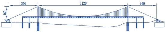
Figure 1.
Configuration of the suspension bridge. (Unit: m).
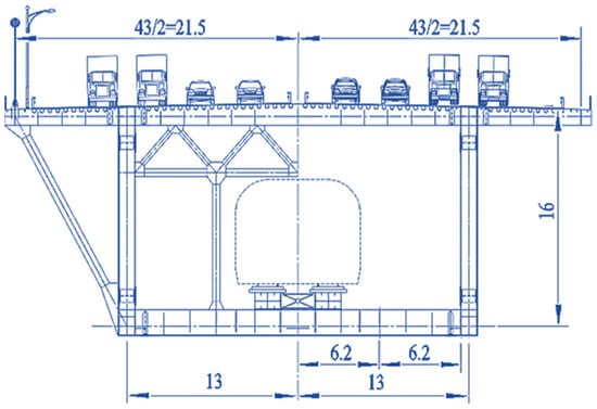
Figure 2.
Cross-section of the bridge girder. (Unit: m).
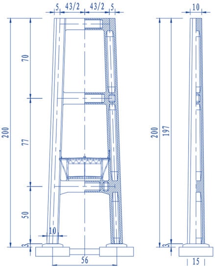
Figure 3.
Main tower of the bridge. (Unit: m).
The finite element model (FEM) of the suspension bridge was established using the large-scale structural analysis software MIDAS [35], as shown in Figure 4. It is assumed that the geometry of the main cable is a quadratic parabola under the action of a dead load, and the finite element types of the bridge model are listed in Table 1. The boundary conditions of the FEM are in consolidation. The values of the first-phase dead load in the calculated load use the main girder included in the uniform load, calculated at 450 kN/m. In the main cable, the winding wire load is 2.11 KN/m; the inspection aisle load is 2.0 kN/m; the sling load is 2.8 kN/m; and the cable clamp loads are 3.5 KN/m (midspan) and 1.5 KN/m (side span). The weight of the main tower is automatically calculated by the MIDAS program according to the section, and the structural coefficient is 1.05. The whole bridge model has a total of 7777 nodes and 18,532 elements.
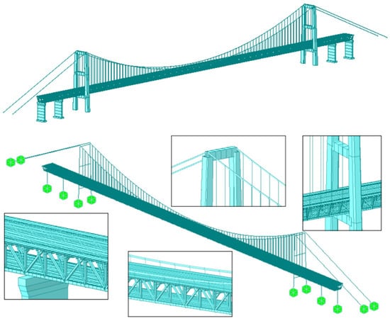
Figure 4.
FEM of a suspension bridge.

Table 1.
FEM types of bridge model.
2.2. Geometric Nonlinearity
The stiffness of the suspension bridge mainly comes from the cables with a considerable initial tension of the dead load, and the stiffness of the main beam contributes a small proportion to the whole bridge. Therefore, the main difference in mechanical properties between suspension bridges and other bridge structures is that the cables have gravitational stiffness, and they will produce large deformations under the action of external loads. Therefore, the internal force and deformation cannot be analyzed by linear theory, and the influence of component internal force and structural displacement should be considered, that is, a nonlinear analysis must be used [36].
The geometric nonlinear effects of long-span suspension bridge structures are mainly reflected in three aspects: the influence of the weight of the main cable, the initial internal force of the cables, and the large displacement of the structure [37], which will be introduced as follows:
- Influence of the weight sag of the main cable
The relatively simple method to deal with this nonlinear effect is to correct the elastic modulus of the cable material, that is, the equivalent elastic modulus is used to reflect the actual ability of the cable to resist the elastic deformation of the material and the weight sag. The Ernst formula is used for calculation, and the nonlinear weight sag effect problem is transformed into a linear problem for analysis. The specific form of the formula is as follows:
where the meaning of each variable can be found in the reference [38] and will not be described in detail here.
- Influence of the initial internal force of the cable
The main cable has a certain initial internal force under a constant load so that it can maintain a certain geometric shape. When the following load is applied, the geometric shape of the main cable changes, and the internal force of the dead load is resistant to the deformation of the following state, which is usually called gravity stiffness. Usually, when the suspension bridge is analyzed, the weight of the main cable and the initial internal force generated by the dead load in the main cable and sling under the completed state is calculated, and the structural stiffness is obtained by applying the initial internal force and changing its geometric shape.
- Influence of a large displacement of the structure
A suspension bridge structure is usually discretized into a three-dimensional finite element model consisting of beam, rod, and plate elements.
As an example, the displacements corresponding to the x, y, and z coordinate axes of the spatial beam element are represented by u, v, and w, respectively. The geometric nonlinear relationship between strain and displacement is considered [39]:
where the last term in the formula is the nonlinear term, which represents the strain due to the interaction of bending and axial deformations, and the first three terms are the strain due to axial and bending displacement.
Considering Hooke’s law , the potential energy of the element can be calculated using the following formula
where the items in Equation (3) are expanded and simplified, and the stiffness matrix of the element can be obtained as
where represents the element stiffness matrix during bending deformation, and reflects the geometric nonlinear characteristics of the element, and is called the element geometric stiffness matrix.
The nonlinear relationship between the displacement and strain of the bridge structure is considered to calculate the vibration responses of the bridge by considering the influence of large structural displacement to a certain extent. Therefore, the dynamic equilibrium differential equation in the finite element calculation should be rewritten as:
where represents the stiffness matrix related to structural deformation, and is a function of displacement, = + .
Since the displacement of the bridge is always changing with the action of the train and wind loads, the stiffness matrix of the bridge is a function of the displacement . In the nonlinear dynamic calculation of the structure, it is necessary to obtain the stiffness matrix through repeated iterative calculations. The other matrices, such as and , are consistent, and the fixed values remain unchanged throughout the calculation process.
Because suspension bridges are widely used in highway bridges, the dead load accounts for a large proportion of the external load of the structure, and the cables of the bridge have been tightened under the action of the dead load. There is little possibility of large deformation caused by the action of car load, so the current calculation of the geometric nonlinear dynamic problems of suspension bridges is limited to the initial internal force under constant load and the effect of cable sag. The train loads on the suspension bridge will cause a large deformation of the structure, so ignoring the influence of the large displacement would cause a relatively large deviation in the calculated results.
2.3. Bridge Modal Analysis
- The structural internal forces caused by weight and dead load are applied to the cables of the suspension bridge, and the elastic modulus of the suspension bridge is iteratively calculated and corrected by the Ernst formula. The first 50th natural frequencies and vibration modes of the bridge are solved by the subspace iteration method. It can be seen from the calculation results that the first 50th natural frequencies of the suspension bridge are very close, varying between 0.0898 Hz and 1.3563 Hz. The first 10th vibration frequencies and the main vibration mode characteristics are listed in Table 2, and the schematic diagram of some vibration modes is shown in Figure 5. The first mode of the bridge is the lateral vibration of the main girder, with a corresponding frequency of 0.0898 Hz. The vertical vibration of the main girder appears in the fourth mode, with a frequency of 0.1885 Hz. The first torsional of the main girder appears in the 10th mode of the structure at a frequency of 2.3720 Hz. Through finite element modeling and natural vibration analysis, it can be seen that the natural frequencies of the bridge are very low, and it is prone to vibrate due to the excitation of external vehicle loads and wind loads.
Table 2. Mode of vibration and frequency.
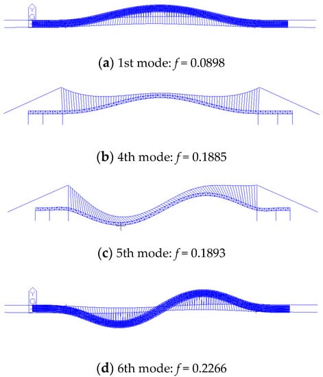 Figure 5. Diagram of partial vibration modes of the bridge. (Unit: Hz).
3. Wind–Train–Bridge Interaction Model
The dynamic interaction between vehicle, wind, and bridge is quite complicated. A corresponding analysis model consisting of three relatively independent and mutually coupled parts, the trained model, the bridge model, and the wind loads model, is established, as shown in Figure 6. The bridge model has been introduced in the previous section, and will not be repeated in this section.
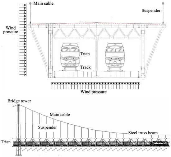
Figure 6.
Dynamic model of the coupled wind–train–suspension bridge system.
3.1. Wind Loads Model
The rivers and strait areas where suspension bridges are built generally have large winds, and the dynamic effects on the suspension bridge and the running train cannot be underestimated.
The wind loads acting on the bridge can be divided into three parts: static wind, buffeting wind, and self-excited wind.
The static wind force is related to the average wind velocity, the cross-sectional size, and the configuration of the bridge. It is constant in the whole calculation process and can be directly applied on the right side of Equation (5). The buffeting wind force is caused by the fluctuating wind and it is the random function of the change in the domain which is related to the fluctuating wind velocity, the external dimensions of the bridge structure, and other parameters. The self-excited wind force is a function of the bridge movement and displacement, which can only be considered in the iterative calculation of the program.
The buffeting wind forces acting on each point of the bridge are calculated according to the formula in [4]. In the calculation, the width of the bridge deck is 26 m, and the distance between the simulated wind velocity points is 14 m. The drag, lift, moment coefficients, and their first derivatives at zero attack angle are 0.904, 0.301, 0.044, 0.1268, 9.827, and 0.9705, respectively, determined by reference [40]. The wind loads acting on the bridge are simplified as the static wind force caused by the average wind, the buffeting wind force caused by the pulsating wind, and the self-excited wind force due to the interaction between the wind and the bridge or vehicle motion. Usually, the static wind force and the buffeting wind force are considered acting on the vehicle, and the formulas are as follows:
where , , and are the drag, lift, and moment caused by static wind on the centroid of the car-body surface, respectively; is the air density; A is the effective windward area, which is approximately equal to the whole windward area of the car body; H is the height from the centroid of the car-body surface to the bridge deck; and , and are the coefficients of drag, lift, and moment, respectively, which are functions of the wind direction. Additionally,
where, , , and are, respectively, the drag, lift, and moment acting on the centroid of the car-body surface and caused by buffeting wind.
In this paper, the wind velocity simulation of 109 nodes on the main girder of the long-span suspension bridge was carried out. To consider the wind effect before the train arrives and after it leaves the bridge, 30 wind velocity points were added both in front of the bridge and along the rear of the bridge. The distance between the nodes is 14 m, kept the same as the beam trusses, and the wind velocity sample length is 600 s. When the average wind velocity is 20 m/s, the simulated lateral and vertical wind velocity time histories are shown in Figure 7, and the buffeting wind load time histories at the main span of the bridge are shown in Figure 8.
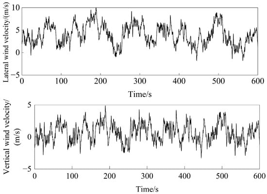
Figure 7.
Simulated wind velocity curve at the bridge midspan.
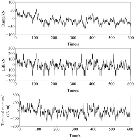
Figure 8.
Simulated wind vibration at the bridge midspan.
3.2. Train Model
Railway trains are composed of locomotives and passenger cars, so the train can be discretized into a series of train models with different structural parameters. Each train is composed of one car body, two bogies, four wheelsets, and the spring and damping connections between the three components. The train model is shown in Figure 9 [41]. It is assumed that the car body, bogie, and wheelsets are all rigid components, neglecting their elastic deformation during vibration. Each car body or bogie has five DOFs to be considered, including lateral, roll, yaw, float, and nod. The three DOFs of lateral, roll, and float are to be considered for each wheelset. The calculation DOFs of each train are 27.
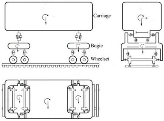
Figure 9.
Train model.
In the model, it is assumed that the wheelset displacement of the train model is composed of the displacement of the bridge at its location, and the corresponding wheel hunting and track irregularity. The three DOFs of the wheelsets are not independent and they need to be calculated. Therefore, each train has 15 independent DOFs for the car body and front–rear bogies.
The dynamic equilibrium differential equation of one train model can be derived from the Lagrange equation [4] as follows:
where , , and represent the mass, damping, and stiffness matrix of the train subsystem, respectively; the subscripts c, t1, and t2 represent the car body, front bogie, and rear bogie, respectively; , and represent the displacement, velocity, and acceleration vector, respectively; and F is the external force vector on the train. The specific form of each matrix in the formula can be found in reference [42], which will not be repeated in this paper.
When the parameters of one train model are given, its mass matrix, damping matrix, and stiffness matrix are all constant. For different types of locomotives and trailers, the corresponding parameters such as mass, stiffness, damping, size, etc., can be written into an input text for the calculating program according to their actual grouping.
3.3. Wind–Train–Suspension Bridge System Calculation
When the geometric nonlinear factors of the bridge are considered, the motion equation of the wind–train–bridge system can be expressed as
where the subscripts b and v represent bridge and train, respectively; , , and are the static wind force, buffeting force, and self-excited force, respectively; and and are interaction forces between the train and the bridge.
The train model and the bridge model are coupled through the forces acting on the bridge deck by the wheelsets. The wind and bridge systems are coupled through the iterative calculation of the self-excited wind force. The interaction between the three is shown in Figure 10.
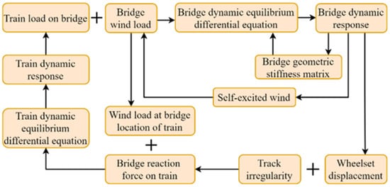
Figure 10.
Coupling action of the wind–train–suspension bridge system.
The bridge data input files are formed by the bridge’s natural vibration frequency and vibration shape calculated by the MIDAS. The train parameters, track irregularity, and wind loads data are written in the input file to be read by the written FORTRAN program. According to the formula in reference [42], the , , and matrix, and the load vector of the bridge and vehicle are calculated and the vehicle–bridge dynamic equilibrium differential equation of Equation (9) is formed and solved. The specific calculating process is shown in Figure 11. Finally, the bridge calculation program NWVB.FOR is developed by the FORTRAN Language.
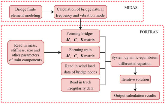
Figure 11.
The function of the FORTRAN calculation program.
The train runs for 10 s under the excitation of track irregularity before boarding. The calculation process of solving the dynamic responses of the train and the bridge in each time step is shown in Figure 12, where cycle j is used to recalculate the structural stiffness based on the bridge displacement. Compared with the constant-value structural stiffness in the linear calculation, the nonlinear calculation is relatively slow, and the integration process is prone to nonconvergence, so the calculated efficiency is quite low.
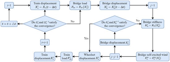
Figure 12.
Process for nonlinear calculation.
4. Wind–Train–Bridge Coupling Vibration Calculation
In this section, the influence of geometric nonlinear factors on the vibration responses of the suspension bridge is studied by calculating the long-span suspension bridge.
4.1. Analysis of the Nonlinear Influence of the Large Displacement of the Structure
In the design stage of the suspension bridge scheme, the internal force state of the structure under the action of weight is approximately taken as the initial state of the nonlinear analysis, and the weight sag of the main cable is corrected by the Ernst formula. The influence of these two nonlinear factors is fully considered when establishing the finite element model. The large displacement factor of the suspension bridge structure is calculated in the integration process. In order to analyze the influence of the large displacement effect on the vibration characteristics of the system, the wind–train–bridge coupling vibration calculation program WVB.FOR and the nonlinear train–bridge calculation program NWVB.FOR are written. In the calculation, the main point number of the key positions of the bridge is shown in Figure 13.
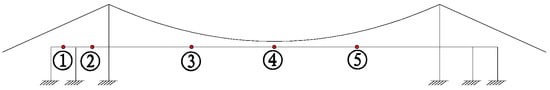
Figure 13.
Output points of the bridge’s dynamic responses.
The train running on the bridge is composed of one SS8 locomotive followed by 18 passenger cars; the train speed is 100 km/h; the track irregularity is the American class-5 spectrum; the bridge structure damping ratio is 2%; the average wind velocity is 10 m/s. The integral step is 0.005 s, which is determined according to the running speed and program convergence. The maximum displacements of each bridge node obtained by the linear and nonlinear calculation programs are listed in Table 3, and the displacement and acceleration time history curves of some nodes at the main span are drawn in Figure 14 and Figure 15.
Table 3.
Maximum dynamic responses of the bridge.
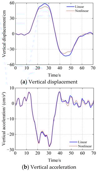
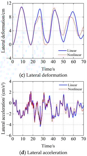
Figure 14.
Displacement and acceleration time histories at point ➂.
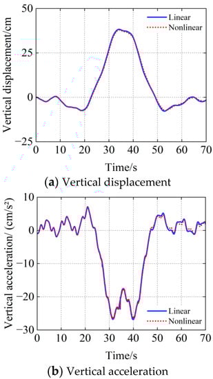
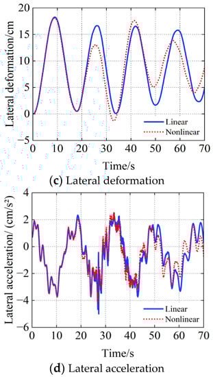
Figure 15.
Displacement and acceleration time histories at point ➃.
- As the first lateral vibration mode of the bridge structure is symmetrical, the maximum lateral deflection occurs at point ➃, which is in the middle of the main span of the bridge. Since the first vertical mode of the bridge is the antisymmetric vibration, the maximum vertical displacement occurs, therefore, at points ➂ and ➄ in the middle of the 1/4 span. The calculation results keep the same with the vibration tendency of the bridge, which shows that the calculation program has good reliability.
- The large displacement nonlinear factor has little effect on the changing tendency of the displacement and acceleration time history curves of the suspension bridge.
- After considering the nonlinear factors of the suspension bridge structure, the displacements and accelerations of the bridge will be significantly smaller than the linear ones. The maximum difference of lateral deformation is 2.53%, and the vertical displacement is 9.62%, which indicates that when the large displacement effect of the structure is considered, the total stiffness of the structure increases due to the existence of geometric stiffness, and the vibration responses are slightly lower than that when nonlinear factors are not considered.
- Compared with the change in acceleration time history curves of each node in Figure 13 and Figure 14, the bridge displacement curves are more obviously changed. Since the first mode of the bridge is lateral, the lateral mode appears more frequently in the first 50th vibration modes. It can be found from the comparison between b and d that the lateral vibration acceleration of the bridge changes more obviously.
Through the above calculation, it can be seen that the nonlinear factors of large displacement have an obvious influence on the dynamic behavior of the suspension bridge structure under the train and wind loads, which should be considered in the calculation.
4.2. Analysis of the Influence of Wind Velocity Changes
The vibration responses of the bridge are calculated when the vehicle speed is 100 km/h and the average wind velocity increases from 0 to 30 m/s. The time history curves of displacement and acceleration are at points ➂, ➃, and ➄, and their changing tendency with wind velocity are shown in Figure 16, Figure 17, Figure 18 and Figure 19. The corresponding maximum responses of each node are shown in Table 4.
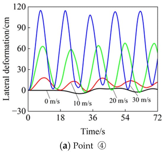
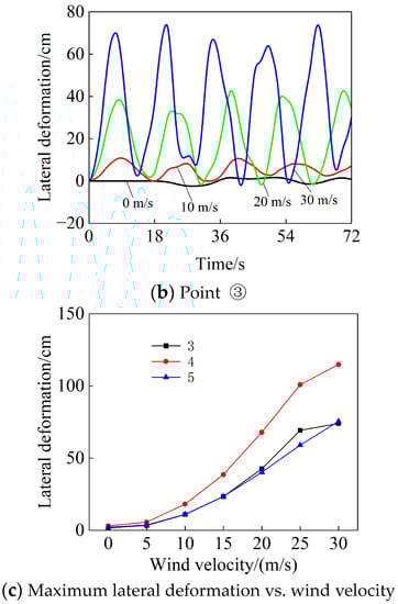
Figure 16.
Changing tendency of bridge lateral deflection with the wind.
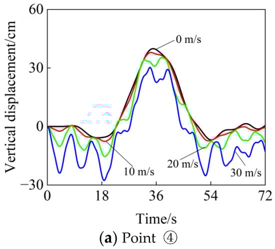
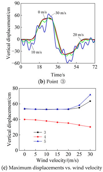
Figure 17.
Changing tendency of the bridge’s vertical deflection with the wind.
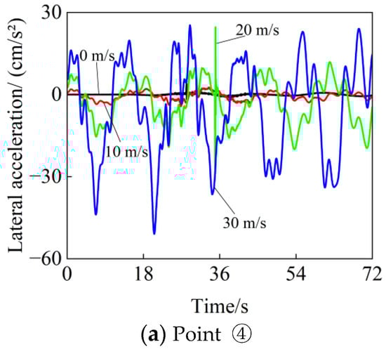
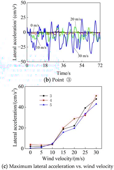
Figure 18.
Changing tendency of the bridge lateral acceleration with the wind.
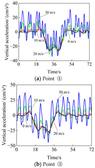
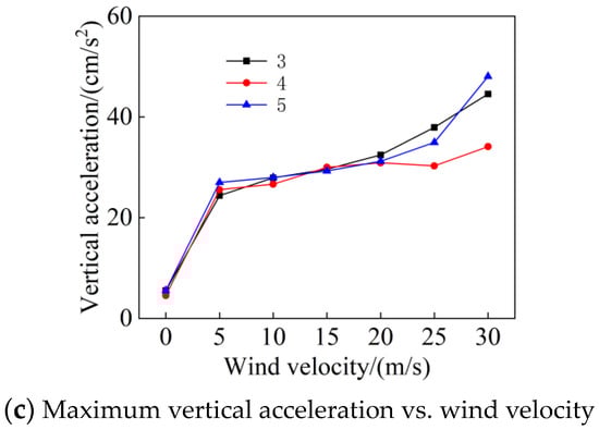
Figure 19.
Changing tendency of the vertical acceleration with the wind.
Table 4.
Maximum bridge responses vs. wind velocity.
It can be seen from the lateral deformation time history curve of the bridge in Figure 16 that the lateral deformation of the midspan point ➂ is much larger than that of the 1/4 midspan point ➃, which conforms to the vibration law of bridge natural vibration modes. Based on the data in Table 3, it can be seen that without considering the wind loads, the lateral deformation of point ➂ caused by the yaw force of the train is 3.0 cm, and the displacement of point ➃ and point ➄ is close to the maximum of 1.7 cm and 2.1 cm, respectively. However, if the wind velocity increases to 30 m/s, the maximum displacement of point ➂ reaches 114.8 cm, and points ➃ and ➄ also reach 73.9 cm and 75.5 cm, respectively, an increase of 38 times, 43 times, and 36 times. The slope of the maximum lateral deformation with wind velocity in Figure 16c is very large, which proves the sensitivity of the long-span suspension bridge lateral deformation to wind loads.
- The vertical displacement time history curves of the bridge and the changing tendency of the maximum with the wind velocity are plotted in Figure 17. It can be seen that when the wind velocity is small (≤20 m/s), the vertical displacement of the bridge is not very sensitive to the wind loads. The time history curves of vertical displacement under different wind velocities in Figure 17a,b are close. The maximum vertical displacement of the bridge decreases slightly due to the wind loads. The maximum vertical displacement of the bridge at point ➂ and point ➃ is 39.8 cm and 53.5 cm, respectively, without wind load. However, when the wind velocity increases to 20 m/s, the maximum vertical displacement of the bridge decreases to 35.2 cm and 53.0 cm, which can reflect the lift effect of the wind loads. However, when the wind velocity exceeds 20 m/s, the suspension bridge appears buffeted under the effect of the wind loads and the vertical vibration will intensify. The maximum vertical displacement of some nodes will show an increasing tendency, which can be clearly seen in Figure 17c.
The lateral and vertical vibration acceleration time history curves of the bridge and the changing tendency of the maximum with the wind velocity are plotted in Figure 18 and Figure 19, respectively. It can be seen that when there are no wind loads, the maximum lateral acceleration at point ➂ is 3.9 cm/s2, and at point ➄ it is 0.5 cm/s2, but when the wind velocity increases to 30 m/s, the maximum values of points ➂ and ➄ are increased to 51.0 cm/s2 and 43.1 cm/s2, an amplification of 13 times and 86 times, respectively; the amplification of the corresponding maximum vertical acceleration is 7 times and 8 times, respectively. The maximum values of vertical and lateral acceleration of the bridge increase sharply with the wind velocity.
4.3. Comprehensive Analysis of Wind Velocity and Train Speed
When the train passes the bridge at the speed of 100–200 km/h and the corresponding mean wind velocity ranges from 0 to 30 m/s, the vibration responses of the bridge under the action of different train speeds and average wind velocity are calculated. The changing tendency of the maximum responses of the bridge with train speed and wind velocity are plotted in Figure 20 and Figure 21.
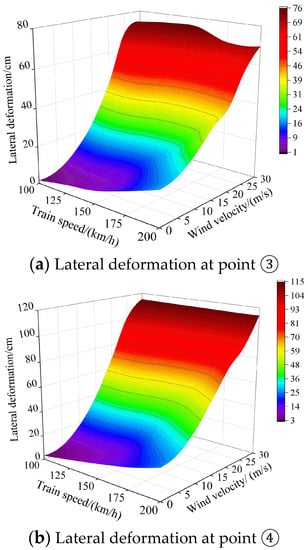
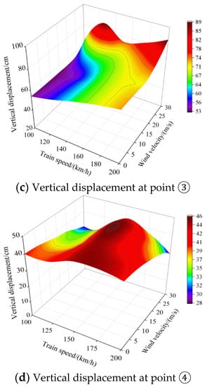
Figure 20.
Changing tendency of bridge displacement with wind and train.
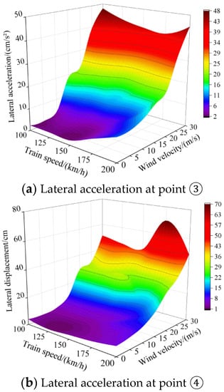
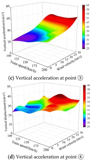
Figure 21.
Changing tendency of the bridge acceleration with the wind and train.
Figure 20 and Figure 21 show that the vibrating responses of the long-span suspension bridge under the simultaneous action of the train and wind loads are as follows:
- The vertical displacement of the bridge is mainly caused by the weight of the train, and the train speed and the average wind velocity have little influence on it.
- When the wind loads are not considered, the maximum lateral deformation of the bridge under the action of the train loads is 25.34 cm, while under the action of wind loads, the lateral deformation increases greatly, and its maximum value reaches 114.8 cm.
- Wind velocity and train speed have a great influence on both the vertical acceleration and lateral acceleration of the bridge.
It can be seen from the above analysis that the lateral deformation of the bridge is more prone to be affected than the vertical displacement under wind load actions. Both the train speed and wind velocity have a great influence on the vibration responses of the long-span suspension bridge. When the vibration response analyses of the wind–train–bridge system are carried out, all kinds of working conditions should be fully considered. Therefore, the most dangerous load combination can be obtained, and the most effective wind and vibration resistance design can be implemented accordingly.
5. Conclusions
In this paper, the geometric nonlinear factors of the suspension bridge structure are considered, a wind–train–suspension bridge dynamic analysis model is established, and the influences of the large displacement factor of the structure, wind velocity, and train speed on the dynamic responses of the suspension bridge are calculated in detail. The conclusions are as follows:
- The large displacement nonlinear factor of the structure does not affect the changing tendency of the displacement and acceleration time history curves of the bridge, but it will reduce the calculated value more than those under the linear factors. The error in the vibration acceleration of the bridge is smaller than that of the displacement when considering the large nonlinear displacement of the structure.
- (1)
- The suspension bridge’s natural frequency is very low; it is very sensitive to wind loads and it is easy to produce wind–train–bridge coupling vibration. When the wind velocity is small, the vertical displacement of the bridge is mainly affected by the gravitational force loading of the vehicle; when the wind velocity is large (≥20 m/s), the buffeting effect of the bridge caused by the wind will induce a large vertical displacement.
- (2)
- The changes in train speed and average wind velocity have a great influence on the maximum bridge displacement. The vertical and lateral accelerations of the bridge increase sharply with the wind velocity, and the bridge vibration caused by wind loads far exceeds the train’s effect.
Therefore, when long-span railway suspension bridges are designed, the vibration responses under the simultaneous action of the wind and train loads should be simulated, and the nonlinear coupling effect of the wind–train–bridge system should be considered to ensure the safe operation of the bridge and train. This research can provide a reference for the design and operation of long-span suspension bridges. For the long-span suspension bridge, the coupling effects of multilane traffic load conditions, as well as field testing will be further studied in the future.
Author Contributions
Conceptualization, S.W. and X.W.; methodology, S.W. and X.W.; software, S.W.; validation, S.W. and X.W.; formal analysis, S.W. and X.W.; data curation, X.W.; writing—original draft preparation, X.W.; writing—review and editing, X.W., Q.Y. and M.G.; supervision, S.W., H.Q. and N.Z.; funding acquisition, H.Q. All authors have read and agreed to the published version of the manuscript.
Funding
This research was funded by [The National Natural Science Foundation of China] grant number [52208140] and [The Scientific Research Project of Beijing Municipal Education Commission] grant number [KM202210016010].
Institutional Review Board Statement
Not applicable.
Informed Consent Statement
Not applicable.
Data Availability Statement
All data included in this study are available upon request by contact with the corresponding author.
Conflicts of Interest
The authors declare no conflict of interest.
References
- Guo, W.W.; Xia, H.; Karoumi, R.; Zhang, T.; Li, X.Z. Aerodynamic effect of wind barriers and running safety of trains on high-speed railway bridges under cross wind. Wind Struct. 2015, 20, 213–236. [Google Scholar] [CrossRef]
- Liu, Q.K.; Zheng, Y.F.; Liu, X.B.; Ma, W.Y. Wind loads, wind induced vibrations and control of cables of cable-stayed bridges. Eng. Mech. 2015, 32, 1–7. [Google Scholar] [CrossRef]
- Zhang, T.; Guo, W.W.; Xia, H. Aerodynamic characteristics of vehicle-bridge system under crosswinds and effect of wind barriers. J. China Railw. Soc. 2013, 35, 102–106. [Google Scholar]
- Zhang, M.; Zhang, N.; Xia, H. Analysis on wind-vehicle-bridge dynamic interaction for long-span railway suspension bridge. China Railw. Sci. 2013, 34, 14–21. [Google Scholar]
- Zhang, N.; Xia, H.; Guo, W.W. Vehicle-bridge interaction analysis under high-speed trains. J. Sound Vib. 2008, 309, 407–425. [Google Scholar] [CrossRef]
- Li, Y.L.; Qian, Y.Z.; Zhu, J.; Huang, X. Longitudinal vibration characteristics of a long-span highway suspension bridge under stochastic wind and traffic loads. China J. Highw. Transp. 2021, 34, 93–104. [Google Scholar]
- Li, Y.L.; Xu, X.Y.; Yan, N.J.; Deng, J.T.; Xiang, H.Y. Comparison of wind-vehicle-bridge coupling vibration characteristics of three-line and three-tower suspension bridge. J. Traffic Transp. Eng. 2015, 15, 17–25. [Google Scholar]
- Li, Y.L.; Dong, S.F.; Zang, Y.; Qiang, S.Z. Coupling vibration of wind-vehicle-bridge system for long-span road-rail suspension bridge and resistant-wind criterion of running train. Eng. Mech. 2012, 29, 114–120. [Google Scholar]
- Li, Y.L.; Qiang, S.Z.; Liao, H.L.; Xu, Y.L. Dynamics of wind–rail vehicle–bridge systems. J. Wind Eng. Ind. Aerod. 2005, 3, 483–507. [Google Scholar] [CrossRef]
- Guo, W.H.; Hong, X.M.; Chen, C.X. Coupled vibration of train and bridge under high-speed trains passing each other in crosswind. China Railw. Sci. 2020, 41, 48–56. [Google Scholar]
- Montenegro, P.A.; Barbosa, D.; Carvalho, H.; Calçada, R. Dynamic effects on a train-bridge system caused by stochastically generated turbulent wind fields. Eng. Struct. 2020, 211, 110430. [Google Scholar] [CrossRef]
- Wang, Z.J.; Tang, T.F.; Guo, X.R.; Zou, Y.F. Influence of wind attack angle on aerodynamic characteristics and coupled vibration of vehicle-bridge system. J. Railw. Sci. Eng. 2022, 19, 752–759. [Google Scholar]
- Liu, Q.J. Coupled vibration research of wind-vehicle-bridge of light rail-cum-road suspension bridges. J. Wuhan Univ. Technol. 2014, 36, 107–113. [Google Scholar]
- Li, X.Z.; Liu, D.J.; Jin, Z.B. Analysis of train-track-bridge coupled vibration of a railway long-span suspension bridge. Steel Constr. 2010, 25, 6–12+71. [Google Scholar]
- Zhai, J.P.; Li, M.; Zhang, J.Y.; Lv, F.M. Influence of bridge height on passing performance of high speed trains under crosswind. Comput. Aided Eng. 2013, 22, 1–8. [Google Scholar]
- Han, W.S.; Chen, A.R. Time-domain buffeting analysis of cable-stayed bridge considering pylon wind field. Eng. Mech. 2007, 24, 123–128. [Google Scholar]
- Zhang, N.; Tian, Y.; Xia, H. A train-bridge dynamic interaction analysis method and its experimental validation. Engineering 2016, 2, 528–536. [Google Scholar] [CrossRef]
- Olmos, J.M.; Astiz, M.Á. Non-linear vehicle-bridge-wind interaction model for running safety assessment of high-speed trains over a high-pier viaduct. J. Sound Vib. 2018, 419, 63–89. [Google Scholar] [CrossRef]
- Xiong, Z.L.; Zhu, J.; Zheng, K.F.; Zhang, W.; Li, Y.L.; Wu, M.X. Framework of wind-traffic-bridge coupled analysis considering realistic traffic behavior and vehicle inertia force. J. Wind Eng. Ind. Aerod. 2020, 205, 104322. [Google Scholar] [CrossRef]
- Bao, Y.L.; Li, Y.L.; Ding, J.J. A case study of dynamic response analysis and safety assessment for a suspended monorail system. Int. J. Environ. Res. Public Health 2016, 13, 1121. [Google Scholar] [CrossRef]
- Wu, W.H.; Chen, C.C.; Chen, Y.C.; Lai, G.; Huang, C.M. Tension determination for suspenders of arch bridge based on multiple vibration measurements concentrated at one end. Measurement 2018, 123, 254–269. [Google Scholar] [CrossRef]
- Bonopera, M.; Liao, W.C.; Perceka, W. Experimental–theoretical investigation of the short-term vibration response of uncracked prestressed concrete members under long-age conditions. Structures 2022, 35, 260–273. [Google Scholar] [CrossRef]
- Wang, S.Q.; Ma, Q.; Ren, Y.R.; Yang, Z. Dynamic interaction analysis on wind-train-bridge system of long-span railway suspension bridge. J. Railw. Sci. Eng. 2017, 14, 1241–1248. [Google Scholar]
- Zhou, Z.H.; Liu, R.T.; Zhu, Z.H.; Gong, W.; Yu, Z.W. Train passing analysis on large-span railway suspension bridge based on ANSYS-MATLAB co-simulation. J. Traffic Transp. Eng. 2021, 21, 117–128. [Google Scholar]
- Xu, L.P.; Huo, X.J. Study on stiffness of super-long span rail-cum-road suspension bridge under live load. Railw. Eng. 2021, 61, 5–8+37. [Google Scholar]
- Guan, Q.H.; Li, J.W.; Liu, J.X. Influence of wind-resistant cable on nonlinear areostatic instability mode of long-span pedestrian suspension bridge. Highw. Traffic Sci. Technol. 2022, 39, 103–110. [Google Scholar]
- Zhang, X.J.; Sun, L.L.; Ying, F.B. Three-dimensional nonlinear aerostatic stability analysis of long-span suspension bridges under skew wind. Adv. Struct. Eng. 2022, 25, 2547–2557. [Google Scholar] [CrossRef]
- Shan, Q.W.; Zhang, L.L.; Yan, Z.C.; Yang, J.X. Aerostatic stability analysis of streamline box girder suspension bridge under non-uniform wind. J. Civ. Environ. Eng. 2022, 44, 117–125. [Google Scholar]
- Almutairi, N.B.; Hassan, M.F.; Abdel-Rohman, M.; Terro, M. Control of suspension bridge nonlinear vibrations due to moving loads. J. Eng. Mech. 2006, 132, 659–670. [Google Scholar] [CrossRef]
- Nino, S.D.; Luongo, A. Nonlinear aeroelastic in-plane behavior of suspension bridges under steady wind flow. Appl. Sci. 2020, 10, 1689. [Google Scholar] [CrossRef]
- Boonyapinyo, V.; Lauhatanon, Y.; Lukkunaprasit, P. Nonlinear aerostatic stability analysis of suspension bridges. Eng. Struct. 2005, 28, 793–803. [Google Scholar] [CrossRef]
- Liu, J.S.; Wang, F.; Yang, Y.; Liu, R.H. Nonlinear flutter analysis for a long-span suspension bridge. Shock Vib. 2021, 2021, 1–20. [Google Scholar] [CrossRef]
- Choi, D.H.; Gwon, S.G.; Yoo, H.; Na, H.S. Nonlinear static analysis of continuous multi-span suspension bridges. Int. J. Steel Struct. 2013, 13, 103–105. [Google Scholar] [CrossRef]
- Petrini, F.; Bontempi, F. Estimation of fatigue life for long span suspension bridge hangers under wind action and train transit. Struct. Infrastruct. Eng. 2011, 7, 491–507. [Google Scholar] [CrossRef]
- Yao, Y. Computer Aided Design of Bridge Engineering; Chongqing University Press: Chongqing, China, 2019. [Google Scholar]
- Tang, M.L.; Shen, R.L.; Qiang, S.Z. Analytic theories and software development of spatial non-linearity static and dynamic of long-span suspension bridge. Bridge Constr. 2000, 1, 9–12. [Google Scholar]
- Pan, Y.R. Nonlinear Analysis Theory Method for Suspension Bridge Structure; Science Press: Beijing, China, 2006. [Google Scholar]
- Zhao, H.X.; Zhang, W.M.; Jiang, X.F.; Liu, Z. Calculation method of equivalent elastic modulus of cable sag effect based on catenary. J. China Foreign Highw. 2020, 40, 62–66. [Google Scholar]
- Liu, Z.X.; Sun, Y. Compuation Solid Mechanics, 2nd ed.; Shanghai Jiao Tong University Press: Shanghai, China, 2010. [Google Scholar]
- Xu, H.T.; Liao, H.L.; Li, M.S.; He, Y. Wind tunnel test study of sectional model of baling river bridge. World Bridges 2009, 4, 30–33. [Google Scholar]
- Guo, W.W.; Xiao, H.; De Roeck, G. Dynamic characteristics and coupling vehicle-bridge vibration analysis of the high speed railway Sesia bridge in Italy. J. Vib. Shock 2013, 32, 82–88. [Google Scholar]
- Xia, H.; Zhang, N.; Guo, W.W. Coupling Vibration of Train-Bridge System; Science Press: Beijing, China, 2014. [Google Scholar]


Disclaimer/Publisher’s Note: The statements, opinions and data contained in all publications are solely those of the individual author(s) and contributor(s) and not of MDPI and/or the editor(s). MDPI and/or the editor(s) disclaim responsibility for any injury to people or property resulting from any ideas, methods, instructions or products referred to in the content. |
© 2023 by the authors. Licensee MDPI, Basel, Switzerland. This article is an open access article distributed under the terms and conditions of the Creative Commons Attribution (CC BY) license (https://creativecommons.org/licenses/by/4.0/).