Article

Concrete for Living Walls: Current Status and a New Design Recommendation

by
Ronaldas Jakubovskis
1,2
1
Laboratory of Innovative Building Structures, Vilnius Gediminas Technical University, 10223 Vilnius, Lithuania
2
Department of Reinforced Concrete Structures and Geotechnics, Vilnius Gediminas Technical University, Sauletekio 11, 10223 Vilnius, Lithuania
Buildings 2023, 13(12), 3067; https://doi.org/10.3390/buildings13123067
Submission received: 15 November 2023 / Revised: 5 December 2023 / Accepted: 7 December 2023 / Published: 8 December 2023

Abstract

:
Concrete may be a promising material for application in living walls, broadening existing vertical greening systems and, most importantly, reducing installation costs. This study presents the concept of layered living concrete (LLC) wall panels that were developed and field-tested over the past 3 years. Simultaneously with long-term field observations, several laboratory studies on the selection of a rational concrete mix composition were carried out. Based on field data, the results of laboratory tests, and numerical simulations, a new LLC wall panel design was proposed. The new panel design retains the previous idea of a layered structure suitable for natural colonization by plants, but also adds improved material characteristics, rational dimensions, the economical use of water, and, potentially, the ability to hasten the greening of vertical surfaces.

1. Introduction

Vertical greening systems may effectively compensate for the lack of green spaces in densely populated urban areas. Vegetated walls may not only contribute to the physical and mental health of residents, but can also mitigate the effect of heat islands [1], reduce energy consumption for heating and cooling [2], sequester carbon dioxide [3], act as an air filter capturing small particulate matter [4], and contribute to storm water management by reducing the runoff of rainwater into the streets [5].
“Vertical greening system” is a general term for both green façades and living walls [6]. Historically, green façades were the oldest type of vertical greening, where climbing plants, supported either directly or indirectly, formed vegetation on the wall. Living walls, where plants are supported directly on the wall by framed boxes, a felt system, or specific plant modules [2,6,7], represent a fairly recent innovation. Living walls have the advantage of the rapid greening of the entire building surface without height limitations, and generally feature broader biodiversity [6]. However, current living wall systems are fairly expensive, with installation costs reaching up to 400–600 EUR/m2 [8]. In addition, long-term maintenance expenses may even exceed installation costs [9]. The high costs of existing living wall systems are mainly related to the complex installation of felts, plant modules, anchoring, support, and irrigation systems. As a result, practical applications of living walls are scarce, with specific luxury projects being rare exceptions [10].
To simplify the installation and maintenance of living walls, an alternative idea has been developed: growing plants directly on a concrete surface [11]. By using concrete as a growing substrate, the need for trays, fixing systems, or specific mats can be eliminated. As a result, the installation costs of concrete living walls may fall several times, eventually becoming comparable to commonplace stone cladding. Despite their numerous potential benefits and possible huge impact on the sustainability of buildings, very few studies have considered the development of concrete living walls [9,12,13,14,15,16,17].
Pervious concrete, featuring high porosity and excellent water permeability, was selected as a material for plant growth by Riley et al. [9] and Hemalatha et al. [12]. The voids in pervious concrete may be filled with soil, accommodating the development of root systems and providing nutrients for plant growth. It has been demonstrated that pervious-concrete-based living walls may principally host the growth of different plant species; however, the long-term survival of plants has not been evidenced. The system presented by Riley et al. [9] suffered from substrate erosion, as the external pervious concrete layer was too flat. As a result, only grasses, sedums, and mosses survived after the first winter (the panels were installed in a humid subtropical climate, in Lyon, France). Similarly, only short-term growth results were reported by Hemalatha et al. [12], where stem-cut or seeded plants (Portulaca gradiflora; Trigonella foenum-graecum) were manually inserted into the soil-filled pervious concrete panel. In the latter study, the growth of plants was examined only in a greenhouse conditions.
An alternative approach to green a concrete surface involves using bio-receptive concrete mixes [13,14,15,16,17]. Bio-receptivity is described as the aptitude of a material to be colonized by living organisms without necessarily undergoing any bio-deterioration [18]. As bio-colonization is a natural process, bio-receptive panels have great potential to further reduce the price of concrete living walls. Several attempts have been made to develop bio-receptive concrete panels, mostly by selecting the proper surface texture, roughness, porosity, and chemical composition of concrete. An in-depth analysis on factors affecting concrete bio-receptivity may be found in a study of Stohl et al. [19]. Nevertheless, the development of lower plants (mosses, lichens, and algae) has been obtained only under ideal greenhouse conditions, with the rapid degradation of the developed biofilm after exposure to the natural environment [14]. In addition, façade panels were kept horizontally, thus, facilitating the development of biofilm in a greenhouse [16].
The greening ability of bio-receptive concrete has mostly been studied in laboratory or greenhouse conditions by evaluating the development of lower plants in time periods lasting from several weeks to a few months [14,15,16,17]. To the best of the author’s knowledge, no long-term (at least multi-year) data on the survivability of living concrete walls have been reported so far. The current study presents the concept of layered living concrete (LLC) wall panels that were developed and field-tested over the past 3 years. The first test series began in March 2021. Ongoing tests of LLC wall panels have proved the greening appearance of this pervious concrete decorative surface after almost 3 years of exposure to an open environment. Based on field observations of long-term plant growth, the second series of LLC panel field tests began in April 2023. In total, 16 LLC panels are currently being examined for their long-term natural greening ability. The present paper summarizes the insights gained from the long-term testing of LLC wall panels and presents a new design recommendation for the further development of living concrete walls. The rest of the paper is organized as follows: First, the general considerations in choice of LLC wall system are discussed (Section 2). Next, laboratory tests on the mechanical and physical properties of concrete along with the numerical simulations are presented (Section 3). Based on the results of laboratory tests and numerical outcomes, a new LLC wall panel design was proposed (Section 4). Finally, the main research outcomes were summarized in Section 5.

2. The Concept of a Living Layered Concrete Panel

The spontaneous growth of lower plants (mosses, fungi, lichens, and algae) on a building’s façade is commonly accepted as unpleasant, and may indicate material degradation (i.e., increased surface roughness, porosity, and water retention) or a lack of maintenance. However, in recent years, natural colonization has attracted a different perception: these plants increase biodiversity, contribute to thermal performance, control storm water, and may even be aesthetically pleasant [19]. Nevertheless, the natural growth of lower plants is a long-term process, as they take at least a decade to colonize the surface of a structure. Moreover, such colonization can appear only on specific bio-receptive surfaces under suitable environmental conditions.
The primary motivation behind the development of LLC façade panels was the creation of a specific environment suitable for the faster natural growth of lower plants. A bio-receptive surface must feature proper physical properties: surface roughness, an irregular texture, and the ability to retain water. Pervious concrete satisfies all of these requirements and also has excellent water permeability, allowing the almost free movement of irrigation and storm water. However, building façades must possess low water retention, and must be impervious and durable. Therefore, an LLC panel was designed from two layers: (1) a pervious, lightweight concrete layer featuring high porosity, permeability, and bio-receptivity; and (2) a high-strength, fibre-reinforced layer made from high-performance concrete (HPC), which acts as a shield for thermal insulation and ensures the structural integrity of the panel segment. To host the growth of lower plants (and some higher lithophyte species), a triangular surface texture was created in the pervious concrete layer. During the initial concept study (field test Series 1), mosses and several indigenous plant species (Sedum acre, Sedum rupestre, Saxifraga paniculata, Sempervivum tectorum) were manually planted in these triangular indentations (Figure 1). In total, four panels (600 × 400 mm) with different orientations were produced and installed in a region with a humid continental climate according to the Köppen classification (54.5803808708009° latitude, 25.518531410974067° longitude). Additional water was provided via a drip irrigation system, without additional nutrients. After 3 years of natural exposure, most of the planted species had survived and some new indigenous species had developed. These initial field tests proved the ability of the proposed LLC system to sustain the long-term growth of plants with minimal maintenance.
The manual installation of plants on these walls is extremely labor-intensive and impractical for large-scale applications. To simplify the production technology and ensure the natural bio-colonization of the wall panels, a specific degradable material, hereinafter referred to as bio-booster, was developed and used for the production of 12 additional LLC panels (field test Series 2). The main purpose of the bio-booster was to accelerate the natural wall colonization process in the selected panel regions, thus, controlling the aesthetic appearance. After several trials, forest topsoil and recycled paper pulp (in a 1:1 mass ratio) were selected as the main constituents of the bio-booster. Forest topsoil naturally contains bacteria, spores, and seeds from indigenous plants (mosses, fungi, and grasses) that germinate in the appropriate environmental conditions. The cellulose fibres from the recycled paper pulp provide strength and stiffness to the topsoil, facilitating the manufacturing process and allowing the formation of complex geometrical shapes (Figure 2a). Under suitable environmental conditions (the bio-booster was kept constantly wet, with an average daily temperature ≥ 5 °C), the initial germination of mosses was observed after 2–3 months, both in the laboratory and during field exposure (Figure 2b,c). Moss cushions developed on the bio-booster 12–24 months after test initiation (Figure 2b).
The design of the LLC panels allows the initial greening process to be hastened by externally applying additional grass seeds. These grasses germinated 1–2 weeks after application, forming visible green regions within 1–2 months (Figure 2d). Nonetheless, in the long term, the domination of mosses is expected if nutrients are not provided via the irrigation system. More details on the production technology and the material composition of the panels from test Series 2 may be found elsewhere [20]. Several important insights were garnered from the initial LLC panel tests:
  • Structural HPC is critical for optimizing cost, installation efficiency, and weight. The price of commercially available ultra-high-performance (UHPC) concrete mixes may range between 1500–2500 EUR/m3 [21], mostly due to expensive steel fibres, the large amount of high-grade micro-fillers, and the use of fine quartz sand [22]. In this respect, the use of more economical HPC mixes composed of natural sand, non-pure filler materials and synthetic fibres may be economically feasible;
  • The mechanical properties of HPC must be suitable for producing thin panels with the largest possible dimensions, thus, reducing material consumption, minimizing weight, and facilitating the installation process. The dimensions of these panels must be optimized with respect to the mechanical properties of the HPC used’
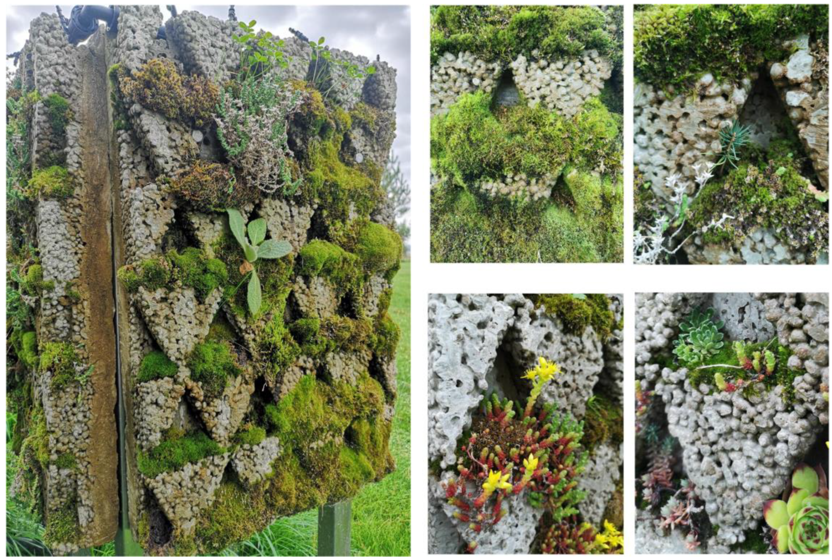
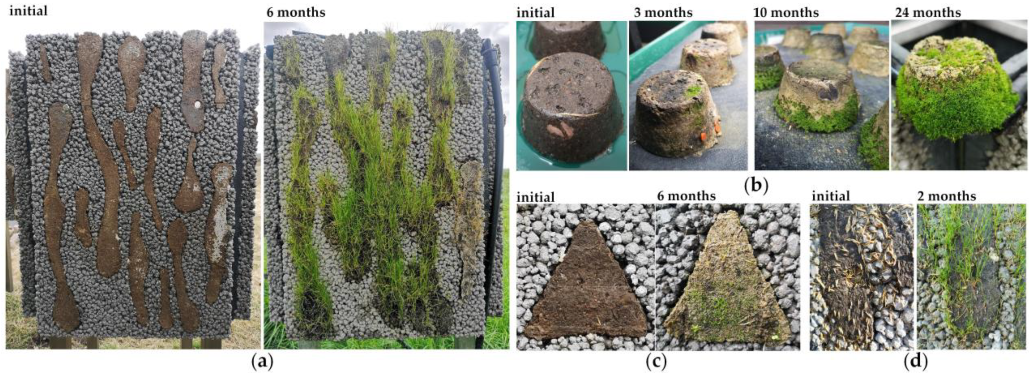
  • The greening efficiency of the LLC panels depends on the shape and distribution of the bio-booster. As the pervious concrete on the panel façade allows the almost free flow of water, a bio-booster serves as a water-retaining reservoir. Consequently, the shape of the bio-booster must be optimized for the more efficient use of storm and irrigation water.
In the present study, the LLC panel was further optimized focusing on the selection of rational panel dimensions and the more efficient distribution of the bio-booster. A numerical simulation was performed for the adjustment of panel size using HPC mechanical properties established from laboratory tests. Based on the field observations of moisture distribution and the growth of plants on the LLC panels, the shape and allocation of the bio-booster were revised and adjusted. The following section presents more details on the laboratory tests performed and the numerical simulations of the LLC panels.

3. The Optimization of the LLC Panel

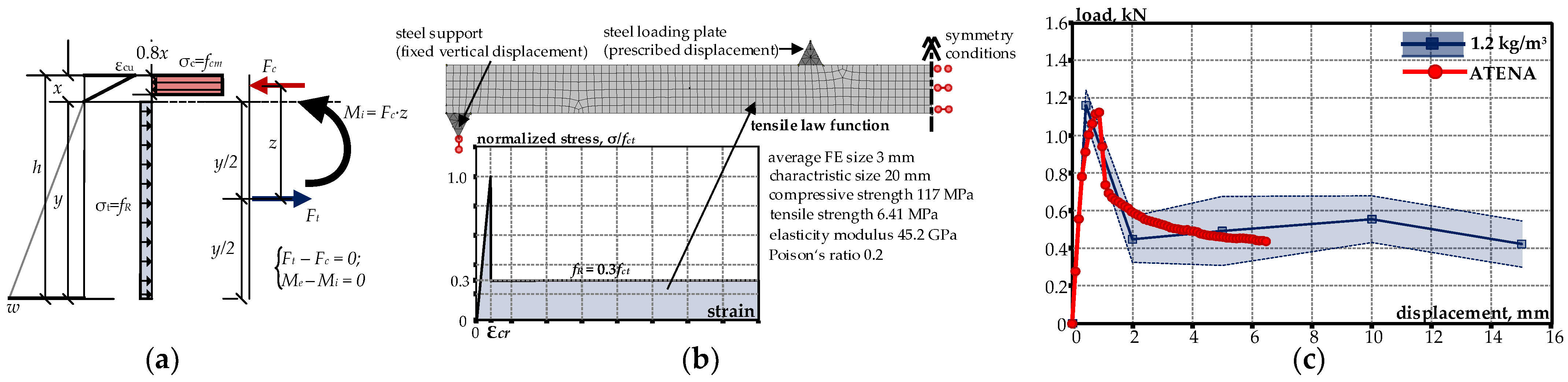
3.1. Laboratory Tests on Synthetic Fibre-Reinforced HPC

The HPC layer in the LLC panel protects the building from the environment, resists seismic and wind loads, and serves as an anchor point for the façade fixing system. To reduce the overall weight and to facilitate the installation process, the thickness of the panels must be minimal. In addition, the HPC must be durable, must possess low water permeability, and must be resistant to the effects of freeze–thaw cycling. All of these requirements may be achieved by using high-strength and non-brittle fibre-reinforced concrete. The high compressive (fc ≥ 110 Mpa), tensile (fct ≥ 6 Mpa), and residual (fR ≥ 2 MPa) strengths of this material allow consumption to be minimized, whereas a dense matrix of HPC ensures that the required durability properties are achieved.
Two experimental attempts to optimize the mechanical and physical properties of HPC were carried out. At the first stage (laboratory test Series 1), several previously developed high- and normal-strength concrete compositions with different amount of synthetic fibre were examined. In total, 24 prisms (30 × 90 × 400 mm) were produced and tested under a four-point loading scheme (Figure 3a–c).
The first set of experiments allowed the minimal reinforcement intensity required in order to achieve the multiple cracking behavior of flexural specimens to be established (12 kg/m3 macro synthetic fibers Durus® EasyFinish, Adfil, Belgium). Multiple cracking indicates a considerable increase in fracture toughness, which is critical for further optimization and the reduction in panel thickness. More information on the mix compositions used, testing techniques, and the results obtained from laboratory test Series 1 may be found elsewhere [20]. In the second stage (laboratory test Series 2), 24 additional prismatic specimens (20 × 90 × 400 mm) were prepared by using a constant dosage of macrofibres (12 kg/m3) and varying microfiber (Crackstop® Ultra, Adfil, Belgium) content from 0 to 3 kg/m3 (Figure 3b). The main research question concerned the determination of whether microfibers can improve the structural toughness on the macro scale, as fairly controversial results have been reported elsewhere in the literature [23,24,25]. The results obtained from the second experimental stage are presented in Figure 3d. Here, the focus is solely on the main outcomes required for further LLC panel development, leaving an in-depth discussion on the effects of fibre hybridization for a separate study. In general, it was found that the synthetic microfibers resulted in only negligible differences in post-cracking strength. Contrarily, a clear tendency towards a smaller crack widths with the increase in microfiber content was observed, especially after crack initiation. Taking into account both the ability to arrest crack propagation and the workability of the concrete, a mix composition with 12 kg/m3 of macro- and 1.2 kg/m3 of microfibers (a 10:1 ratio) was selected for further numerical simulation. Such a ratio of synthetic macro- to microfibers is similar to the results of Sadrinejad et al. [24], who suggested optimal proportions of 9:1.

3.2. Numerical Simulation

Numerical analysis was carried out using the Atena (version 5.9.0.20863) non-linear finite element software [26]. A simple bilinear material model was adopted for tensile concrete, composed of the initial elastic component and constant residual stress, fR. The latter was calculated from the equilibrium conditions of internal forces and bending moments, as schematically shown in Figure 4a. To simplify the solution procedure, the constant distribution of residual stresses was assumed within the tensile zone. Such a simplification may be reasonable for fibre-reinforced concrete, as was demonstrated by Gribniak and Sokolov [27]. The assumed tensile law function for concrete is shown in Figure 4b, along with the other material properties used for the numerical analysis. As may be seen from Figure 4c, the simplified concrete tensile law function results in a reasonably good approximation of the experimentally observed results: the simulated maximal load has an error of 3%, whereas residual strength is mostly within the 95% confidence interval. Thus, this bilinear material model was used in the further numerical simulations.
Next, parametric analysis was performed on LLC panel segments. The task of the simulation was to find the relationships between panel dimensions and load bearing capacity. In general, façade panels are subject to self-weight, wind, and seismic actions, among which wind generally has the most severe adverse effect [28]. In subsequent simulations, only outward wind action was applied (negative pressure), as this induces larger stresses in comparison to inward wind load. In the latter case, part of the load is directly transmitted to the façade system (holding rails), whereas in the case of outward pressure a panel is supported only by anchor bolts.
The simulated panel segment is schematically shown in Figure 5a. Taking advantage of the symmetrical wind load, only 1/4 of the panel was modelled, as shown in Figure 5b. In total, 8 different panel dimensions were analyzed (Table 1), limiting the total panel weight to 50 kg. In all cases, the thickness of the HPC was set to 20 mm, following the requirement of minimal thickness for the undercut fastening systems. The contribution of the light-weight pervious concrete layer to the load-bearing capacity of the LLC panel was neglected.
The results of the numerical simulations are summarized in Figure 5c and Table 1. The maximal negative wind pressure and anchor pull-out force were calculated for all cases. The limiting factors in the analysis were either the fracture of the concrete at the anchor point or the serviceability limit state of the panel. Following the recommendations of Sousa [28], a maximal deflection limit of L/250 was adopted (where L is the shortest side dimension).
The numerical simulations show that the HPC concrete mix allows for a significant increase in panel dimensions in comparison to the sizes of the LLC panels used in both the first and second test series (0.4 × 0.6 m). It was calculated that a 0.6 × 1.2 m panel may still resist 6.6 kN/m2 of negative wind pressure without excessive deformation (the design wind loading is commonly in the range of 2–3 kN/m2 [29,30]). It should be pointed out that these calculations were performed using the average material properties. For structural design purposes, characteristic HPC values should be established along with specific data on wind velocity, terrain conditions, and pressure coefficients. The current simulation also indicate the values of the pull-out forces acting on each anchor point. Based on these results, specific anchor bolts should be selected and further studied in a pull-out test.
A graphical representation of the principal strain distribution at the final loading step is shown in Figure 6. The grey shaded areas show the strain in the concrete below the theoretical cracking strain of 142 µε. Fracture strain limit (ε > 142 µε) was reached in all analyzed cases, resulting in the opening of microcracks in the central parts of the panels. Obviously, larger fractured regions were obtained in smaller panels, which were simulated up to higher loads. The fracture regions in large panels (0.4 × 1.2 m and 0.6 × 1.2 m) were limited due to the lower load intensity, which, in turn, was governed by the serviceability criteria. Such limited fracture strain areas without crack localization may be acceptable due to the non-brittle deformation of fibre-reinforced HPC.
In general, numerical simulations indicate that the simplified tensile concrete law (Figure 4b) may be rationally used for the structural analysis of HPC elements. The application of the simplified concrete material model allowed for the selection of rational LLC panel dimensions that may be further adjusted based on actual building design and wind loads.

4. A New Design Recommendation

The ongoing field tests involving Series 1 and Series 2 allowed several lessons to be learnt regarding the water retention capacity of the panels, the effective shape of the bio-booster, and the natural colonization speed of these panel surfaces. In addition, laboratory tests on HPC composition selection and numerical wall simulations substantiated the selection of the rational LLC panel thickness and dimensions. Based on the field observations, laboratory tests and numerical simulations, the following findings and recommendations are provided:
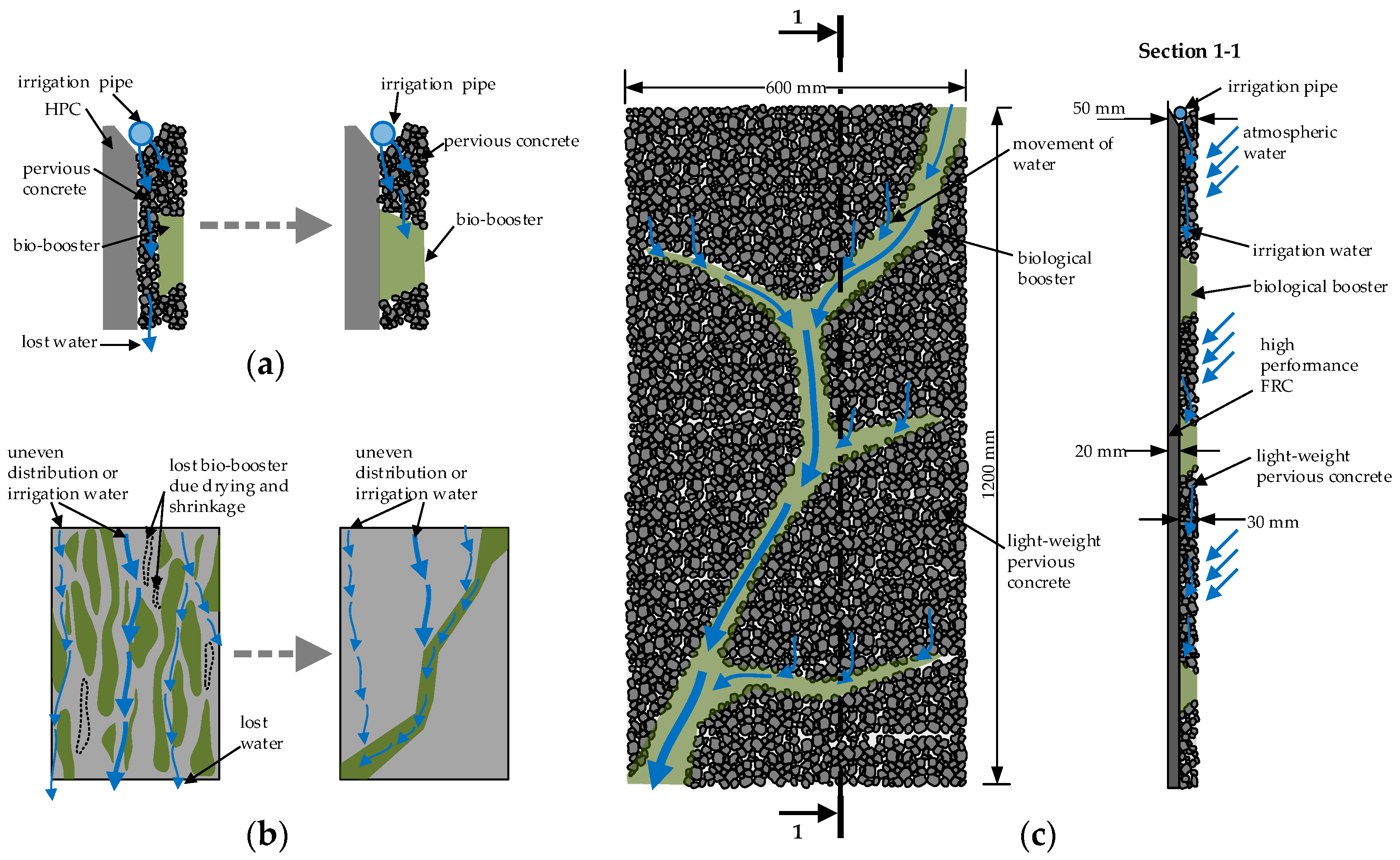
  • The porous concrete on the panel façade allows the almost free flow of water. Some of the irrigation water was lost due to it filtering through the pervious concrete between the HPC and bio-booster layers. For the more efficient use of water, the bio-booster must be in contact with the UHP concrete layer (Figure 7a);
  • The greening speed of LLC panels is strongly dependent on the moisture distribution and the shape of the bio-booster. The LLC panels in test Series 2 consisted of separated bio-booster inserts of different sizes (Figure 2a), and some of the small elements were lost due to drying and shrinkage. This, in turn, was caused by the uneven distribution of irrigation water. To overcome the problem of uneven water distribution, a continuous bio-booster layer should be produced (Figure 7b);
  • The bio-booster serves as a water-retaining reservoir. To improve the water retention capacity of LLC panels, the thickness of the bio-booster should be increased;
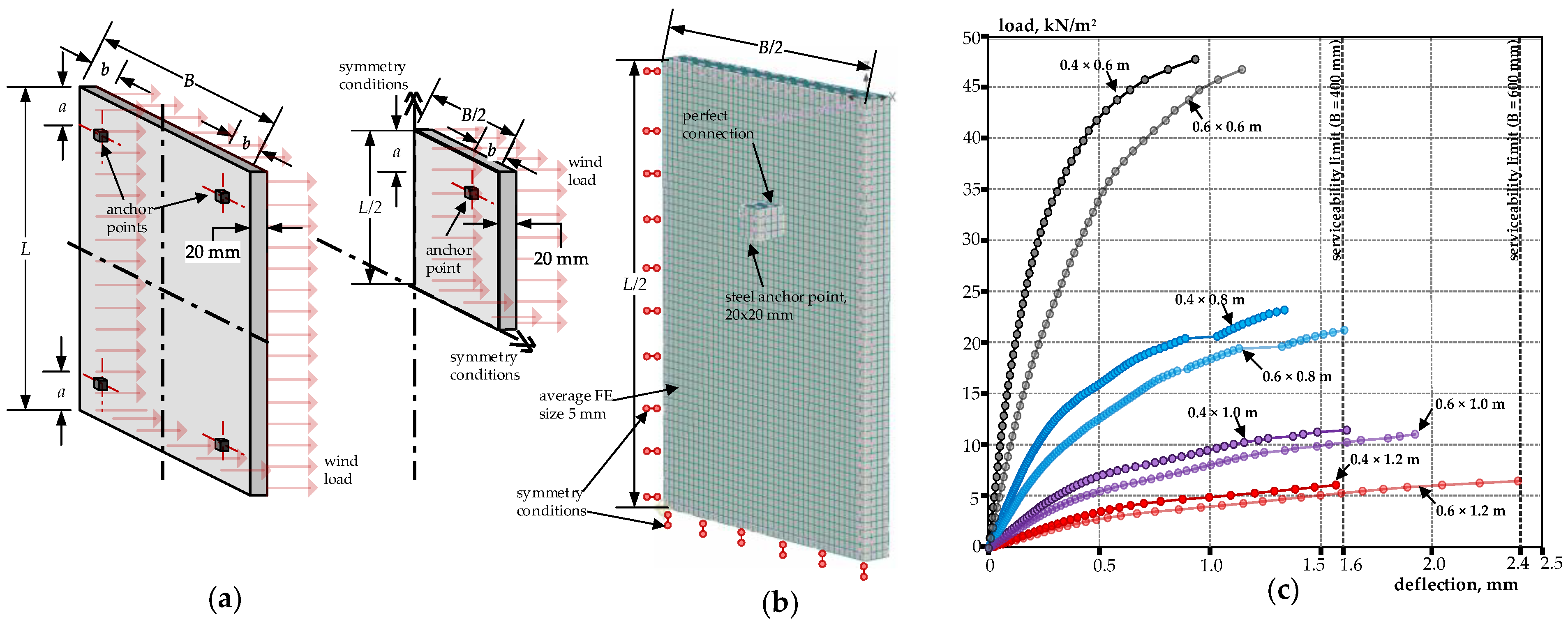
  • The rational thickness of the HPC layer should be 20 mm, taking into account both the economical use of the materials and existing panel fixing methods. Numerical simulations have shown that panels of such thickness, with side dimensions of 0.6 × 1.2 m, may resist strong wind loads without excessive deformation.
Based on these considerations, a new LLC panel design is suggested (Figure 7c). The thickness of the HPC layer is set to 20 mm, whereas the side dimensions of the panel are increased up to 0.6 × 1.2 m. To optimize the use of irrigation water, the LLC panel has a diagonal, river-shaped bio-booster distribution. The continuous bio-booster layer is designed to have direct contact with the HPC layer, contributing to the more efficient use of irrigation water. To improve water retention capacity, the thickness of the bio-booster is increased to 30 mm. It is estimated that the panels of a new design will allow for a significant (30–50%) savings in a use of irrigation water, and, more importantly, steady growth of plants irrespective of the amount of natural precipitation. In fact, LLC panels of field test Series 2 suffered from excessive drying and loss of bio-booster material, especially at the side edges (Figure 2a). The panels of a new design have a diagonally shaped bio-booster that effectively collects both irrigation and atmospheric water, increasing moisture retention capacity and, consequently, the greening performance of the LLC panel. As was observed in the pilot field tests, initial greening areas on the new panels are expected in 3-6 months after panel installation. Several additional years will be required for mosses to grow into a well-developed cushions. Such natural colonization is much slower in comparison to other living walls solutions. For example, pre-vegetated modular panel systems may green the building’s façade almost simultaneously with the installation process [31]. Similarly, hydroponic felt-based systems also allow for a quick growth of the selected and the specifically positioned pre-vegetated plant species [32]. Although the existing modular or felt-based living wall systems allows for a quick greening of a biologically diverse vertical surfaces, the longevity, high installation and the annual maintenance costs are the main concerns of expert consultants and green wall installation managers [33]. In this respect, the LLC panels of a new design have an advantage of an almost maintenance-free system, which evolves and changes naturally. In addition, non-regular diagonal greening allows for an aesthetically attractive building façade texture. Figure 8 shows an example of an idealized façade with LLC panels of the new design.

5. Conclusions

Concrete may be a promising material for living wall applications, broadening existing vertical greening systems and, most importantly, reducing installation costs for green walls. The present study summarized recent activities in the development of concrete living walls, emphasizing the need for new design solutions. Based on long-term observations from ongoing field tests, the laboratory testing of HPC, and numerical simulations, a new design for a concrete living wall panel was proposed. The new panel design keeps the previous idea of a layered structure suitable for natural colonization by plants, but adds improved material characteristics, rational dimensions, the economical use of water and, potentially, the ability to hasten natural colonization. Field test Series 3 is expected to verify the greening performance of panels constructed according to the new design proposed in this paper.

Funding

This research received no external funding.

Data Availability Statement

The author confirms that the data supporting the findings of this study are available within the article.

Acknowledgments

I gratefully acknowledge the help of Dobrawa Berenika Rog for preparing graphical idealization of a living concrete façade.

Conflicts of Interest

The author declares no conflict of interest.

References

  1. Shafiee, E.; Faizi, M.; Yazdanfar, S.A.; Khanmohammadi, M.A. Assessment of the effect of living wall systems on the improvement of the urban heat island phenomenon. Build. Environ. 2020, 181, 106923. [Google Scholar] [CrossRef]
  2. Radić, M.; Brković Dodig, M.; Auer, T. Green facades and living walls—A review establishing the classification of construction types and mapping the benefits. Sustainability 2019, 11, 4579. [Google Scholar] [CrossRef]
  3. Charoenkit, S.; Yiemwattana, S. Living walls and their contribution to improved thermal comfort and carbon emission reduction: A review. Build. Environ. 2016, 105, 82–94. [Google Scholar] [CrossRef]
  4. Pettit, T.; Irga, P.J.; Abdo, P.; Torpy, F.R. Do the plants in functional green walls contribute to their ability to filter particulate matter? Build. Environ. 2017, 125, 299–307. [Google Scholar] [CrossRef]
  5. Ostendorf, M.; Morgan, S.; Celik, S.; Retzlaff, W. Evaluating the potential stormwater retention of a living retaining wall system. J. Living Archit. 2021, 8, 1–18. [Google Scholar] [CrossRef]
  6. Irga, P.J.; Torpy, F.R.; Griffin, D.; Wilkinson, S.J. Vertical Greening Systems: A Perspective on Existing Technologies and New Design Recommendation. Sustainability 2023, 15, 6014. [Google Scholar] [CrossRef]
  7. Manso, M.; Castro-Gomes, J. Green wall systems: A review of their characteristics. Renew. Sustain. Energy Rev. 2015, 41, 863–871. [Google Scholar] [CrossRef]
  8. Manso, M.; Teotónio, I.; Silva, C.M.; Cruz, C.O. Green roof and green wall benefits and costs: A review of the quantitative evidence. Renew. Sustain. Energy Rev. 2021, 135, 110111. [Google Scholar] [CrossRef]
  9. Riley, B.; de Larrard, F.; Malécot, V.; Dubois-Brugger, I.; Lequay, H.; Lecomte, G. Living concrete: Democratizing living walls. Sci. Total Environ. 2019, 673, 281–295. [Google Scholar] [CrossRef]
  10. Riley, B. The state of the art of living walls: Lessons learned. Build. Environ. 2017, 114, 219–232. [Google Scholar] [CrossRef]
  11. Ottele, M.; Koleva, D.A.; van Breugel, K.; Haas, E.M.; Fraay, A.L.A.; van Bohemen, H.D. Concrete as a multifunctional ecological building material: A new approach to green our environment. In Proceedings of the 19th International Symposium Ecology & Safety, Bulgaria, Serbia, 7 June 2010–11 June 2010; Info Invest: Belgrade, Serbia, 2010; pp. 223–234. Available online: https://research.tudelft.nl/en/publications/concrete-as-a-multifunctional-ecological-building-materiala-new-a (accessed on 14 November 2023).
  12. Hemalatha, T.; Ranjit Raj, N.; Gopal, R. Pervious Concrete for Green Walls. J. Archit. Eng. 2021, 27, 06021003. [Google Scholar] [CrossRef]
  13. Manso, S.; Segura, I.; Aguado, A. Cement-Based Multilayer Assembly that Can Be Used as a Biological Support for Building Facades or Other Structures. Patent WO 1594, 3 January 2014. [Google Scholar]
  14. Veeger, M.; Prieto, A.; Ottelé, M. Exploring the possibility of using bioreceptive concrete in building façades. J. Facade Des. Eng. 2021, 9, 73–86. [Google Scholar]
  15. Veeger, M.; Ottelé, M.; Prieto, A. Making bioreceptive concrete: Formulation and testing of bioreceptive concrete mixtures. J. Build. Eng. 2021, 44, 102545. [Google Scholar] [CrossRef]
  16. Mustafa, K.F.; Prieto, A.; Ottele, M. The role of geometry on a self-sustaining bio-receptive concrete panel for facade application. Sustainability 2021, 13, 7453. [Google Scholar] [CrossRef]
  17. Karmoker, U.; Paul, S.J.K.; Ray, P.D.; Chakrabartty, M. A More Bio-Receptive Concrete Façade Design: A Greener Way to Breathe. In Proceedings of the International Conference on Planning, Architecture and Civil Engineering, Rajshahi, Banglades, 12–14 October 2023. [Google Scholar]
  18. Guillitte, O. Bioreceptivity: A new concept for building ecology studies. Sci. Total Environ. 1995, 167, 215–220. [Google Scholar] [CrossRef]
  19. Stohl, L.; Manninger, T.; von Werder, J.; Dehn, F.; Gorbushina, A.; Meng, B. Bioreceptivity of concrete: A review. J. Build. Eng. 2023, 107201. [Google Scholar] [CrossRef]
  20. Jakubovskis, R.; Malaiškienė, J.; Gribniak, V. Bio-colonization layered concrete panel for greening vertical surfaces: A field study. Case Stud. Constr. Mater. 2023, 19, e02394. [Google Scholar] [CrossRef]
  21. Alsalman, A.; Dang, C.N.; Martí-Vargas, J.R.; Hale, W.M. Mixture-proportioning of economical UHPC mixtures. J. Build. Eng. 2020, 27, 100970. [Google Scholar] [CrossRef]
  22. Abdul Sahib, M.Q.; Farzam, M.; Sukkar, K.A. Development and Performance Evaluation of UHPC and HPC Using Eco-Friendly Additions as Substitute Cementitious Materials with Low Cost. Buildings 2023, 13, 2078. [Google Scholar] [CrossRef]
  23. Rasheed, M.A.; Prakash, S.S.; Raju, G.; Kawasaki, Y. Fracture studies on synthetic fiber reinforced cellular concrete using acoustic emission technique. Constr. Build. Mater. 2018, 169, 100–112. [Google Scholar] [CrossRef]
  24. Sadrinejad, I.; Madandoust, R.; Ranjbar, M.M. The mechanical and durability properties of concrete containing hybrid synthetic fibers. Constr. Build. Mater. 2018, 178, 72–82. [Google Scholar] [CrossRef]
  25. Kazemian, M.; Shafei, B. Mechanical properties of hybrid fiber-reinforced concretes made with low dosages of synthetic fibers. Struct. Concr. 2023, 24, 1226–1243. [Google Scholar] [CrossRef]
  26. Červenka, V.; Jendele, L.; Červenka, J. ATENA Program Documentation–Part 1. Cervenka Consult. Sro 2021. [Google Scholar]
  27. Gribniak, V.; Sokolov, A. Standardized RC beam tests for modeling the fiber bridging effect in SFRC. Constr. Build. Mater. 2023, 370, 130652. [Google Scholar] [CrossRef]
  28. de Sousa Camposinhos, R. Stone Cladding Engineering; Springer: Dordrecht, The Netherlands, 2014. [Google Scholar]
  29. Flansbjer, M.; Williams Portal, N.; Vennetti, D. Verification of the structural performance of textile reinforced reactive powder concrete sandwich façade elements. Appl. Sci. 2019, 9, 2456. [Google Scholar] [CrossRef]
  30. O’Hegarty, R.; Kinnane, O.; Grimes, M.; Newell, J.; Clifford, M.; West, R. Development of thin precast concrete sandwich panels: Challenges and outcomes. Constr. Build. Mater. 2021, 267, 120981. [Google Scholar] [CrossRef]
  31. El Menshawy, A.S.; Mohamed, A.F.; Fathy, N.M. A comparative study on green wall construction systems, case study: South valley campus of AASTMT. Case Stud. Constr. Mater. 2022, 16, e00808. [Google Scholar] [CrossRef]
  32. Gandy, M. The ecological facades of Patrick Blanc. Archit. Des. 2010, 80, 28–33. [Google Scholar] [CrossRef]
  33. Gunawardena, K.; Steemers, K. Urban living walls: Reporting on maintenance challenges from a review of European installations. Archit. Sci. Rev. 2020, 63, 526–535. [Google Scholar] [CrossRef]
Figure 1. The LLC façade panel of test Series 1 in a natural environment. After 3 years in field conditions, mosses outgrew the initial triangular cells and began to cover the remaining area of the panel. Higher plants (Sedum, Saxifraga, and Jovibarba) also showed some development; however, in the long term, it seems that mosses will dominate even the southern wall orientation.
Buildings 13 03067 g001
Figure 2. Façade panels containing bio-booster material from field test Series 2: (a) growth of grasses on the panel with the free-form distribution of the bio-booster; (b) natural growth of fungi and mosses on the bio-booster in laboratory conditions; (c) germination and growth of mosses on the LLC panel in a natural environment; and (d) germination and growth of grasses on the bio-booster.
Buildings 13 03067 g002
Figure 3. Laboratory tests on HPC: (a) laboratory test Series 1 specimens; (b) laboratory test Series 2 specimens; (c) test set up; (d) load–displacement diagrams from laboratory test Series 2. Continuous lines represent the average measured displacement values, whereas shaded areas show 95% confidence intervals.
Buildings 13 03067 g003
Figure 4. Numerical simulation of experimental specimens from test Series 2: (a) calculation of residual stresses fR; (b) numerical model with the assumed material properties and boundary conditions; and (c) simulated and experimental load–displacement diagrams for specimens with 12 kg/m3 of macro- and 1.2 kg/m3 of microfibers.
Buildings 13 03067 g004
Figure 5. The numerical simulation of an LLC panel: (a) schematic view of the simulated segment; (b) numerical model with the assumed boundary conditions; and (c) simulated load–displacement response of all panels.
Buildings 13 03067 g005
Figure 6. Principal strain distribution at the final loading stage for all simulated panels. Black lines show the expected micro-cracking regions (crack width filter > 10 µm).
Buildings 13 03067 g006
Figure 7. Recommendations for the new design: (a) placement of the bio-booster, avoiding water loss through pervious concrete; (b) suggested distribution of bio-booster for the more effective use of irrigation and atmospheric water; and (c) a new design proposal for an LLC panel.
Buildings 13 03067 g007
Figure 8. An idealized façade with LLC panels of the new design.
Buildings 13 03067 g008
Table 1. Results of a parametric analysis.
L
[m]
B
[m]
a
[m]
b
[m]
Deflection Limit [mm]Panel Mass [kg]Pressure
Limit [kN/m2]
Pull-Out Force on Anchor [kN]
0.60.40.10.11.616.5048.02.88
0.80.40.10.11.622.1123.41.87
1.00.40.10.11.627.6411.61.16
1.20.40.10.11.633.176.20.74
0.40.60.10.12.424.88464.14
0.80.60.10.12.433.1721.42.57
1.00.60.10.12.441.4611.21.68
1.20.60.10.12.449.756.61.19
Disclaimer/Publisher’s Note: The statements, opinions and data contained in all publications are solely those of the individual author(s) and contributor(s) and not of MDPI and/or the editor(s). MDPI and/or the editor(s) disclaim responsibility for any injury to people or property resulting from any ideas, methods, instructions or products referred to in the content.

