
Column Link Behavior in Eccentrically Braced Composite 3-Dimensional Frames


Abstract
:1. Introduction
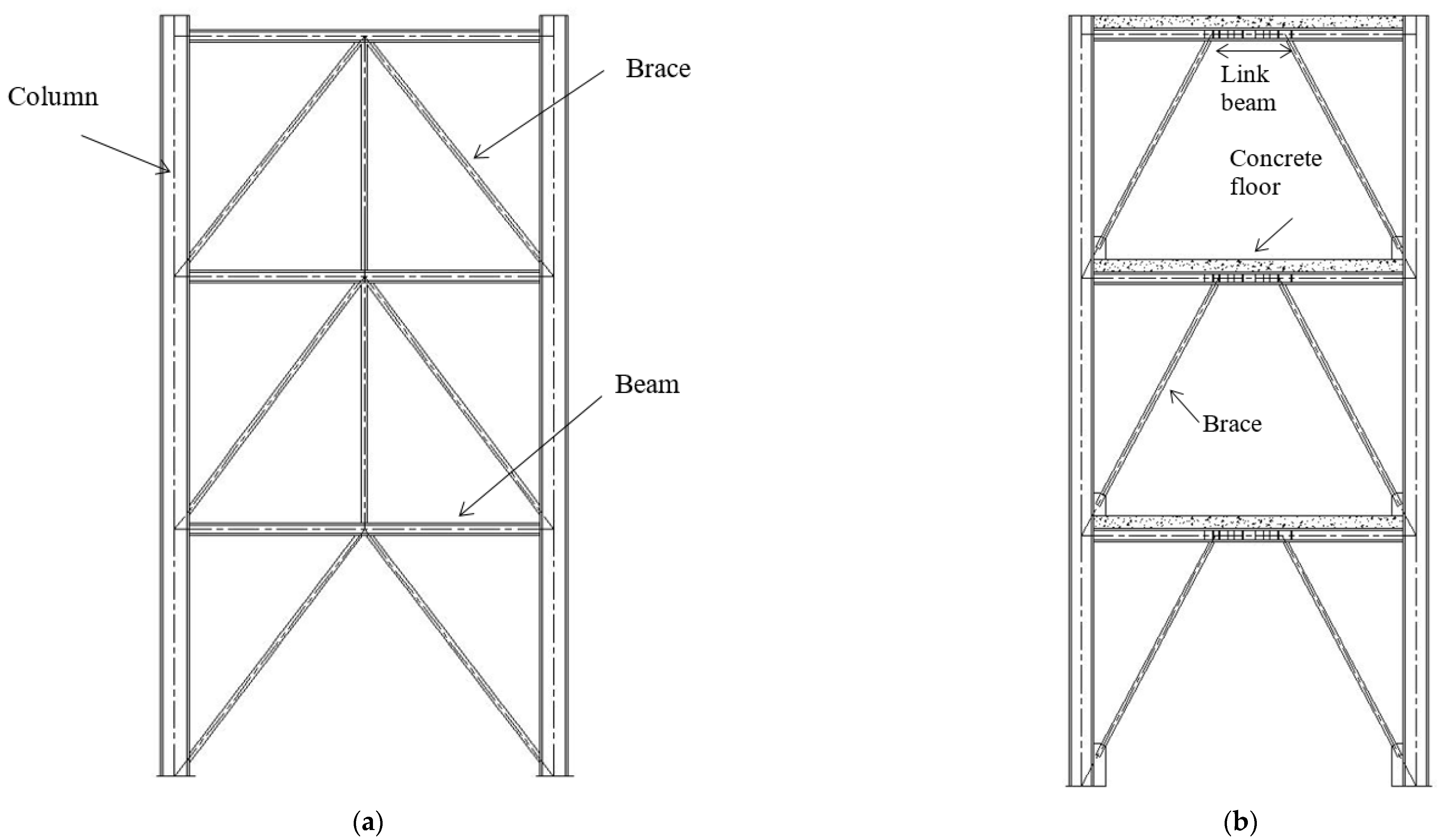
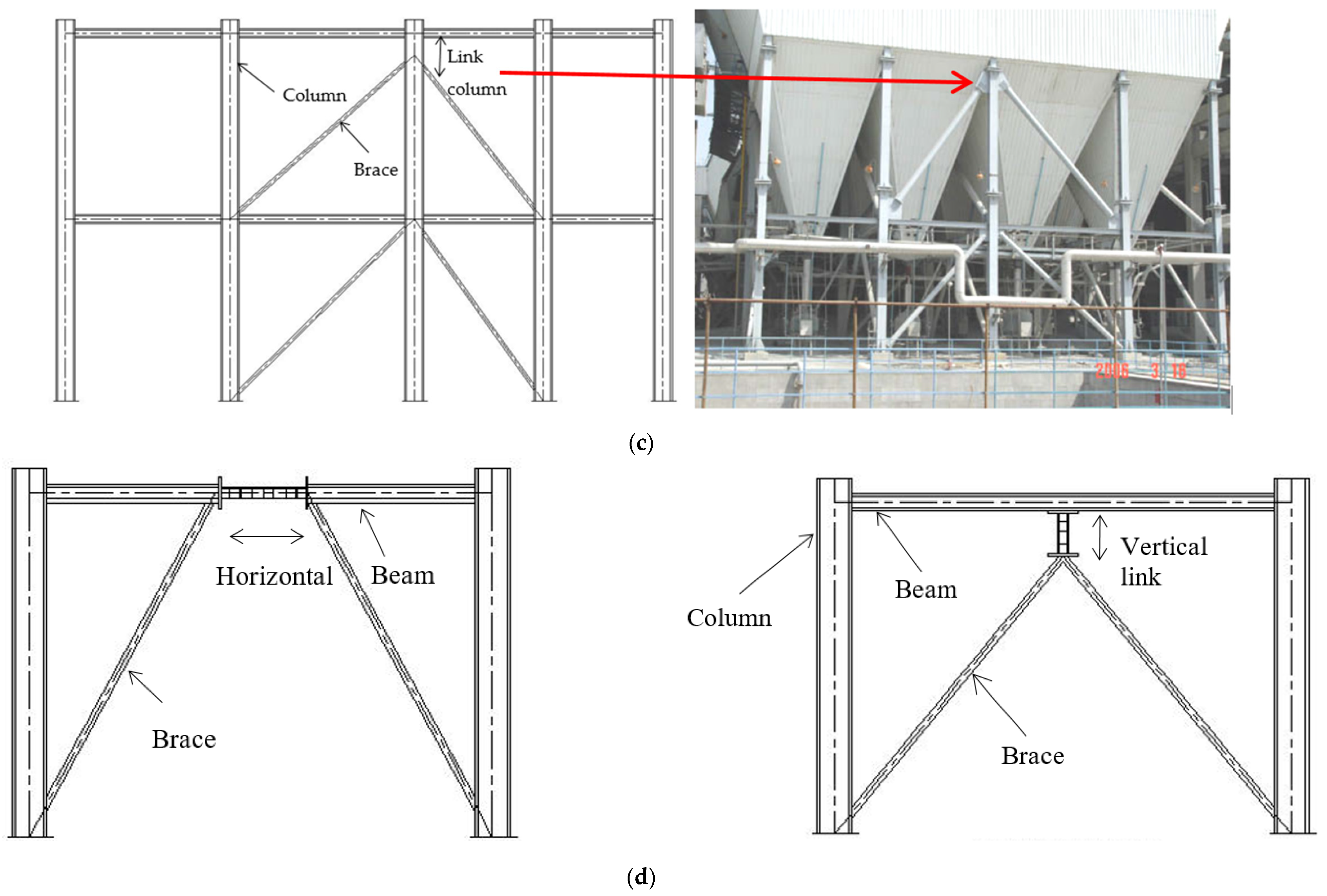
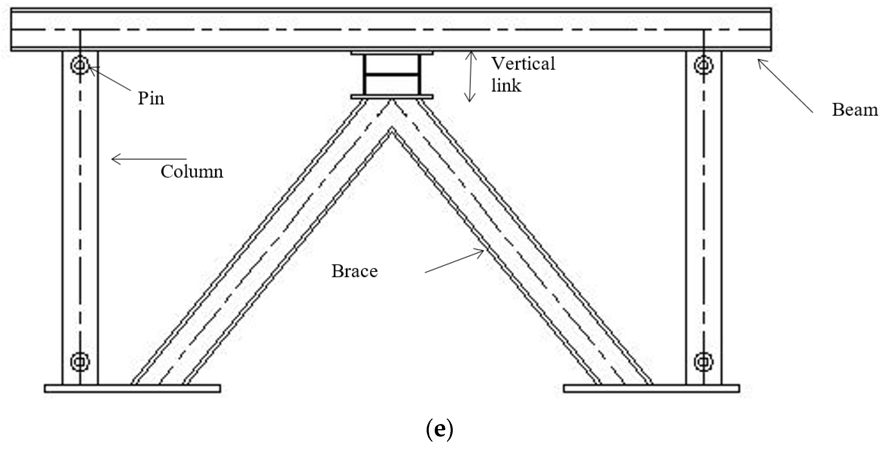
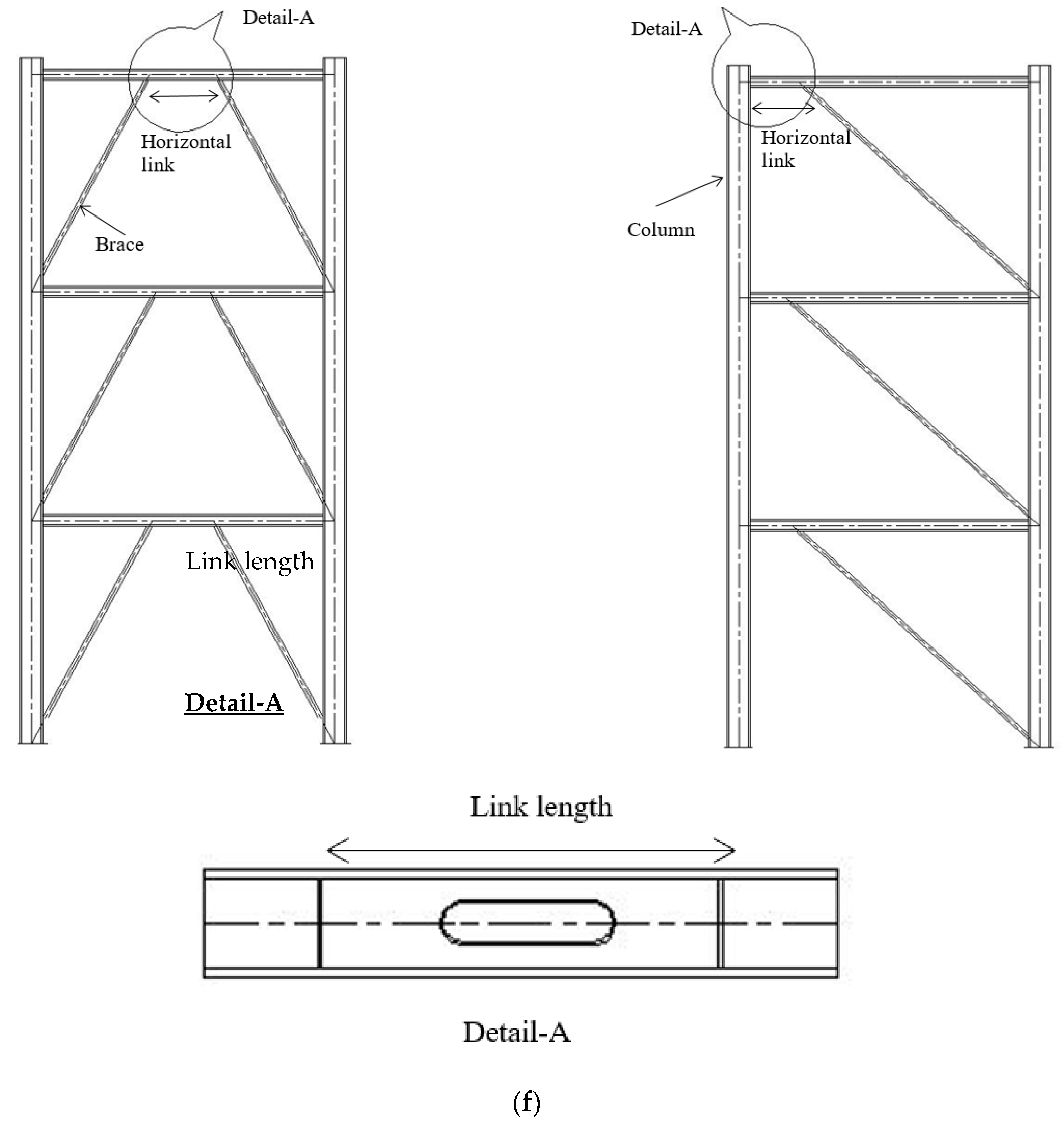
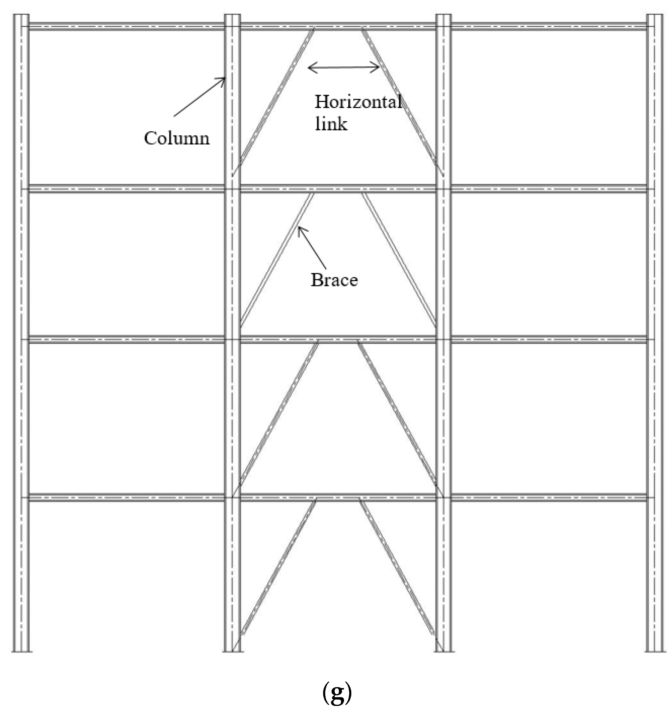
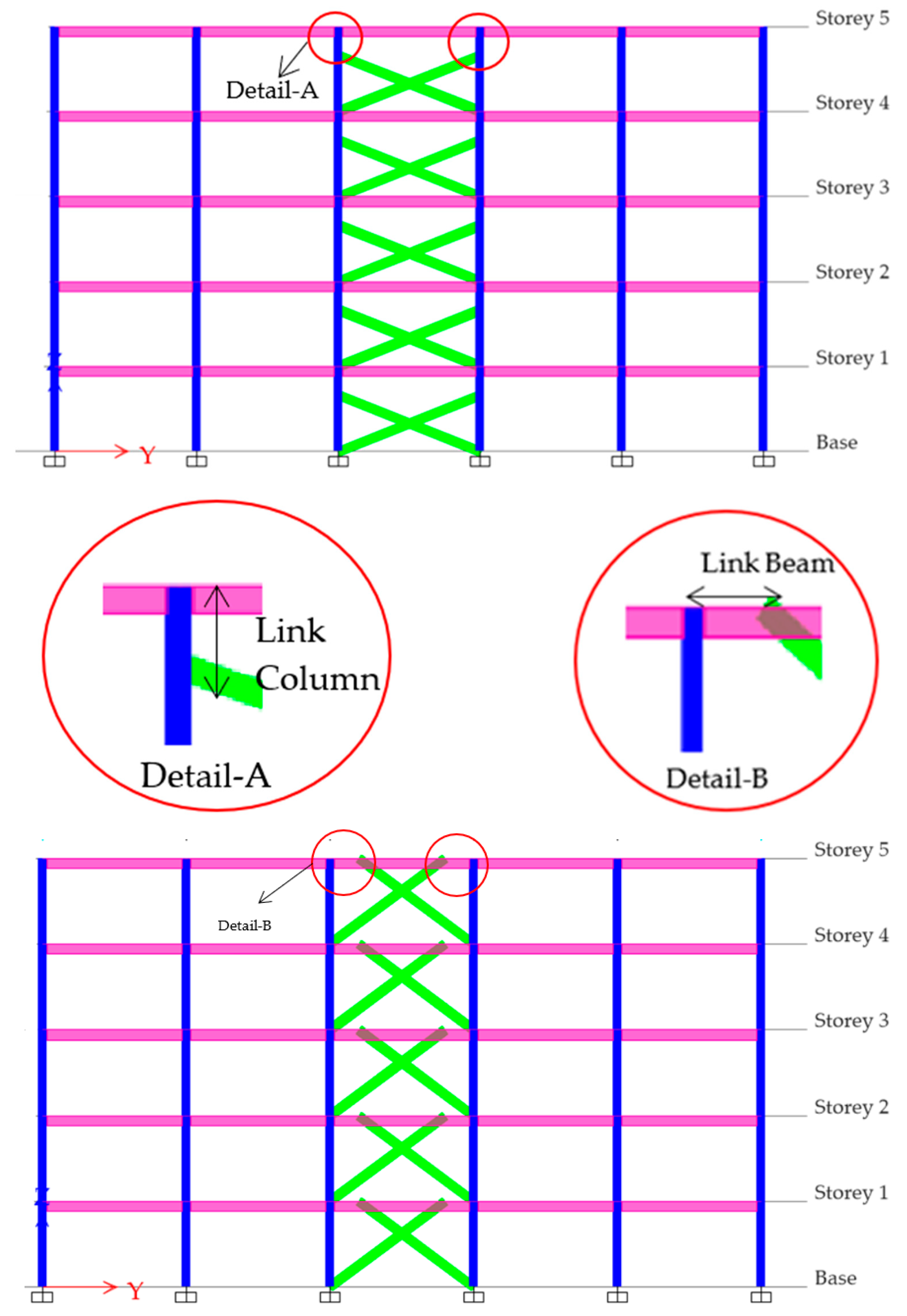
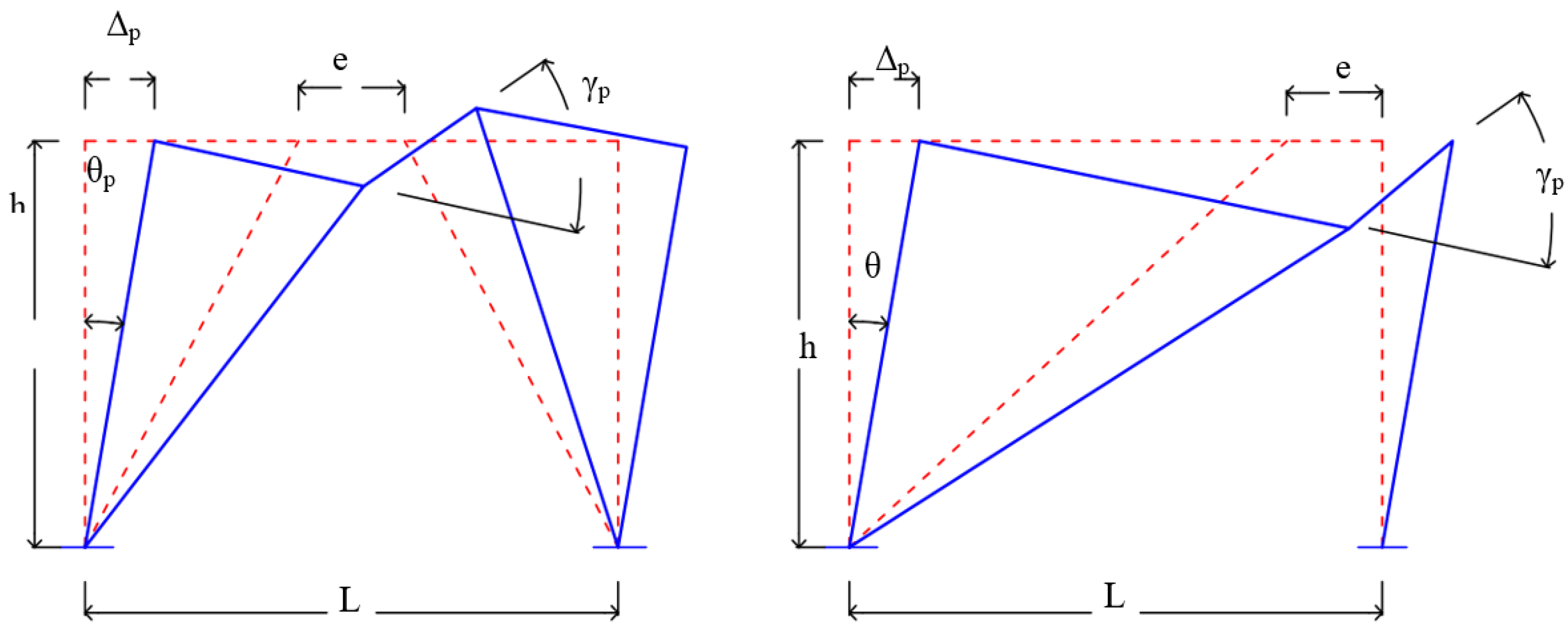
2. Analytical Model
2.1. Nonlinear Analysis
2.2. Design Guidelines by the AISC 341-16 [39], EC3 [40], EC8 [41] and IS 1893:2016 [30]
3. Performance under Seismic Loadings
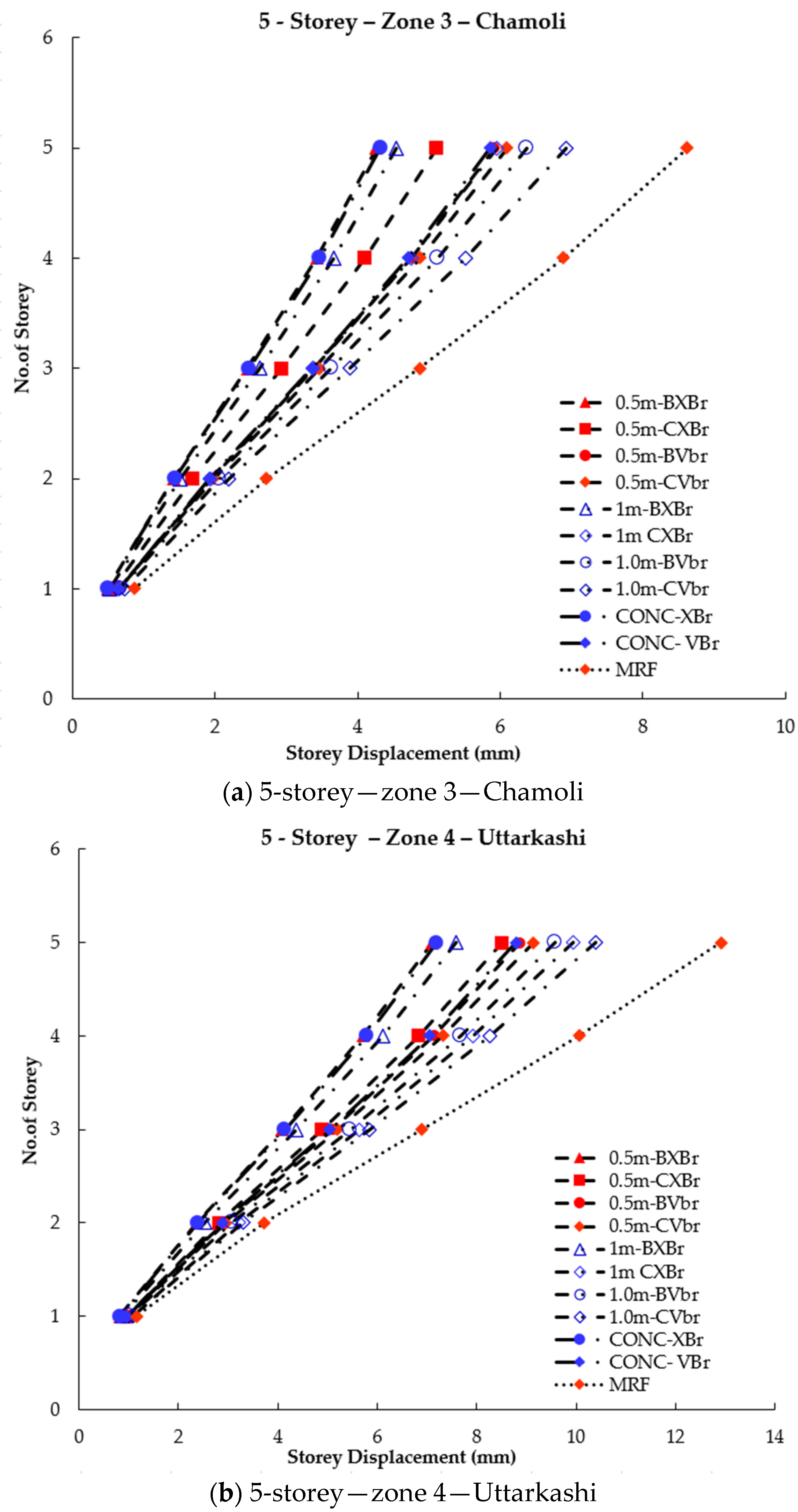
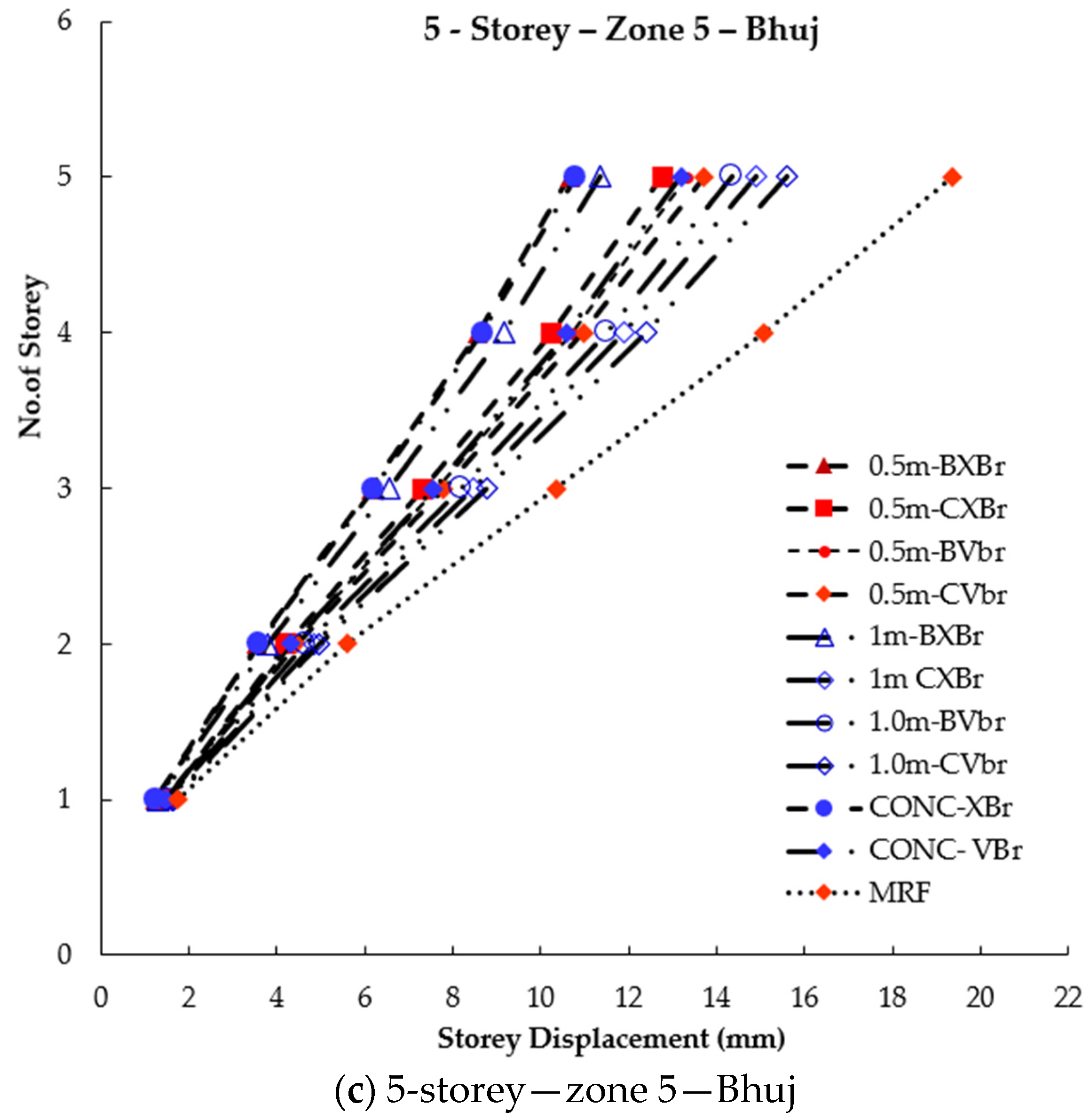
3.1. Storey Displacement
3.2. Inter-Storey Drift Ratio
3.3. Base Shear
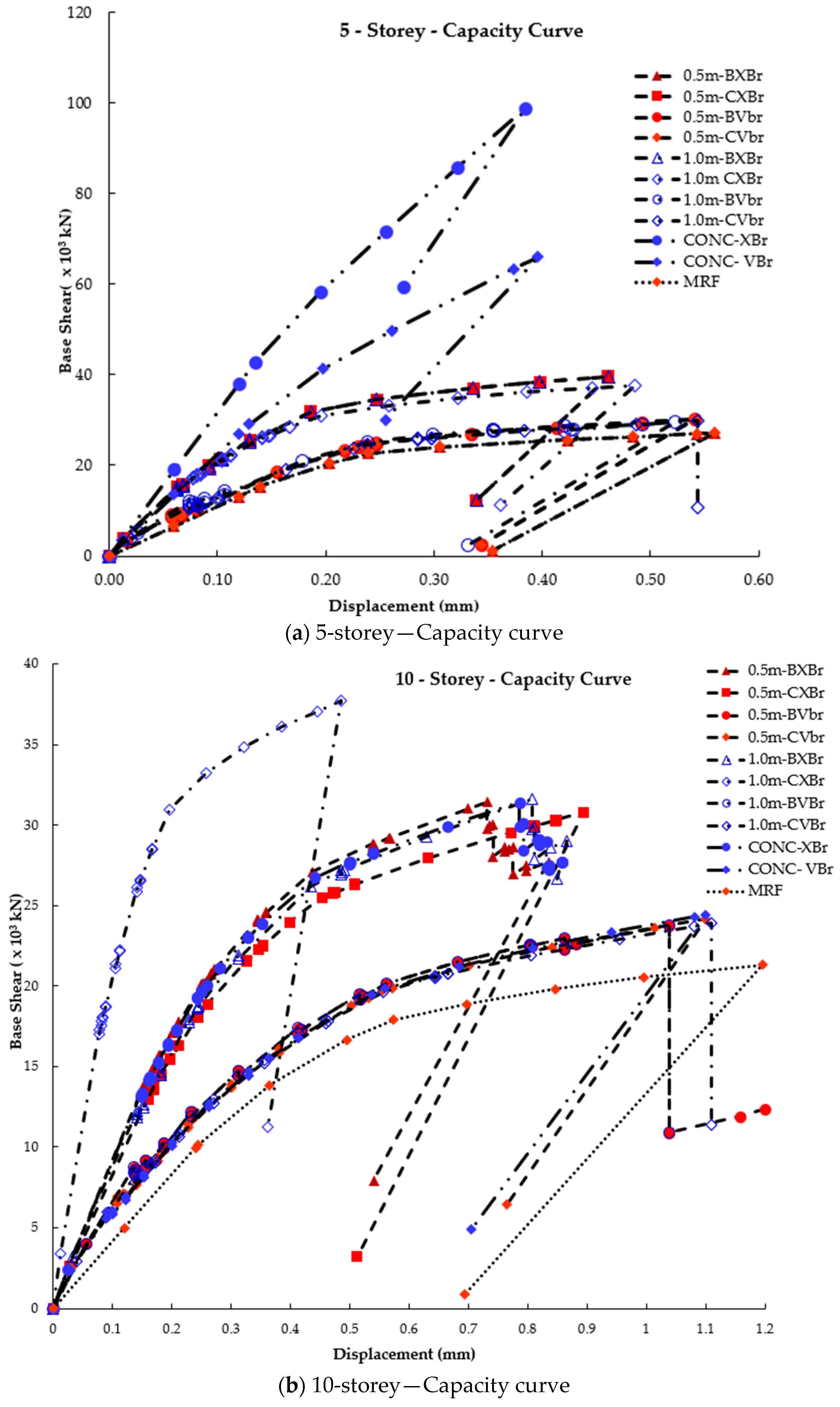
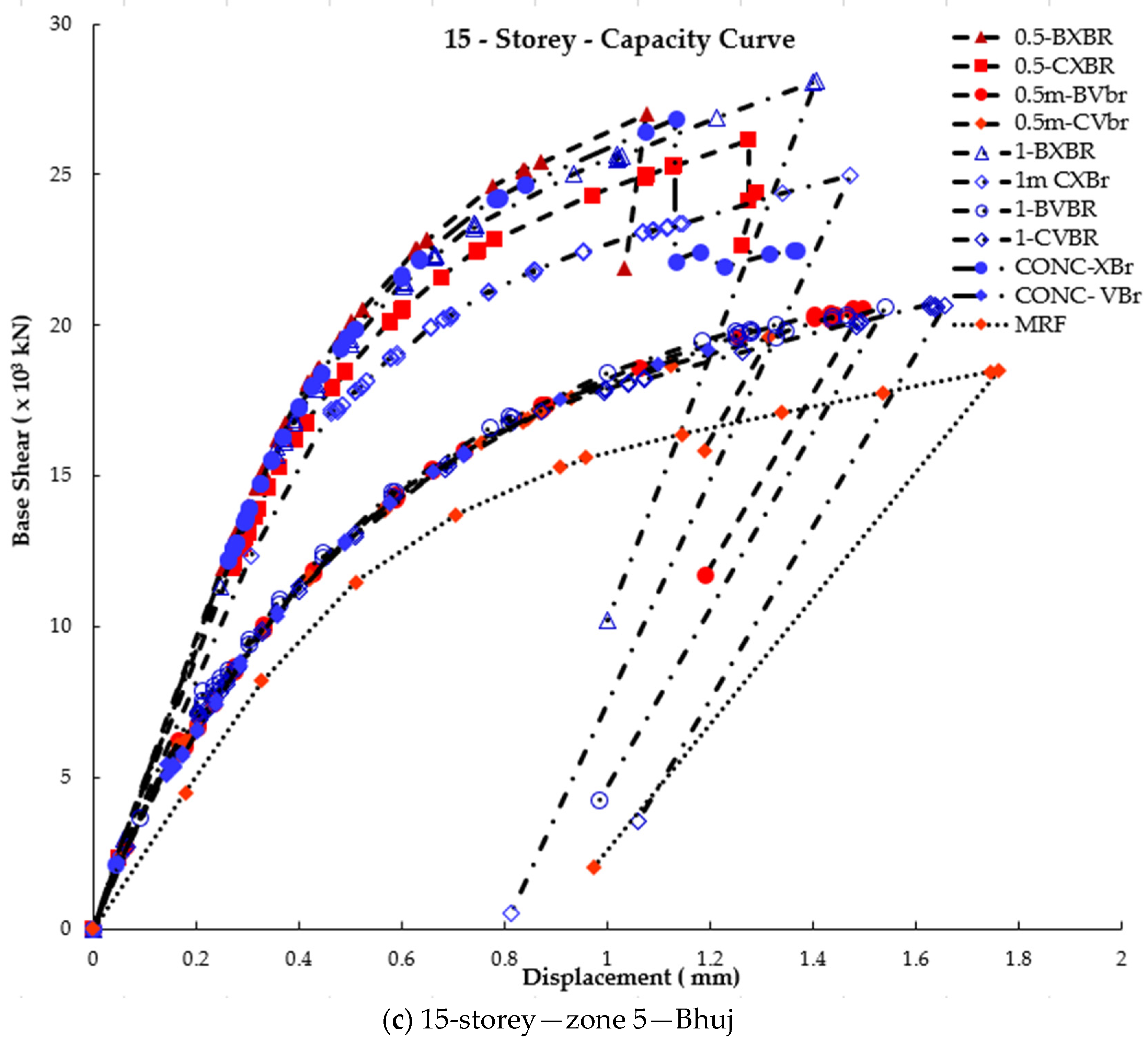
3.4. Capacity Curve
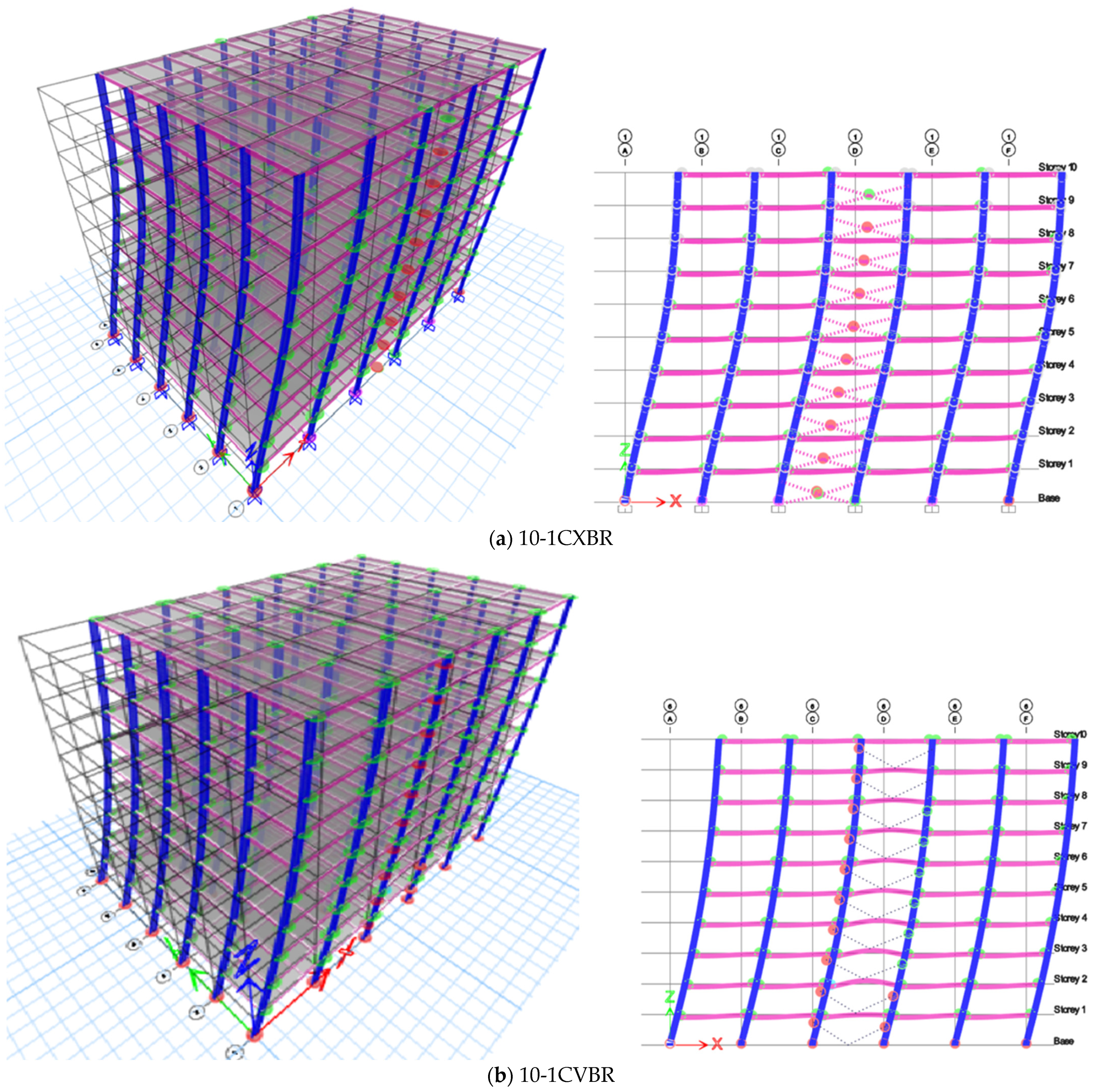
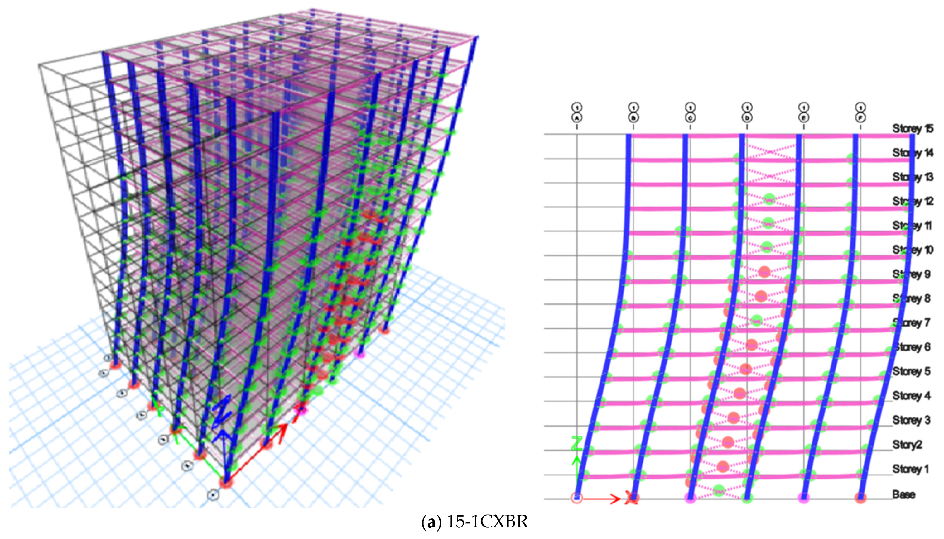
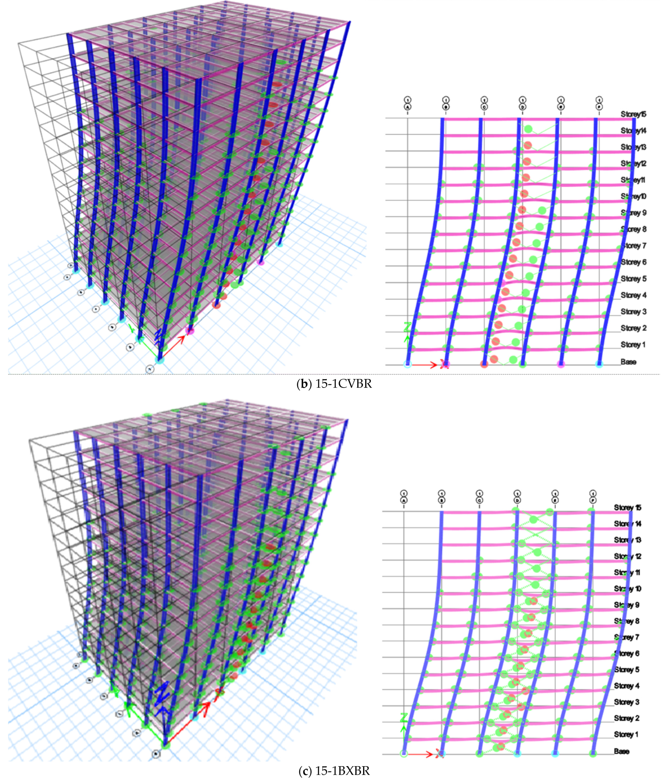
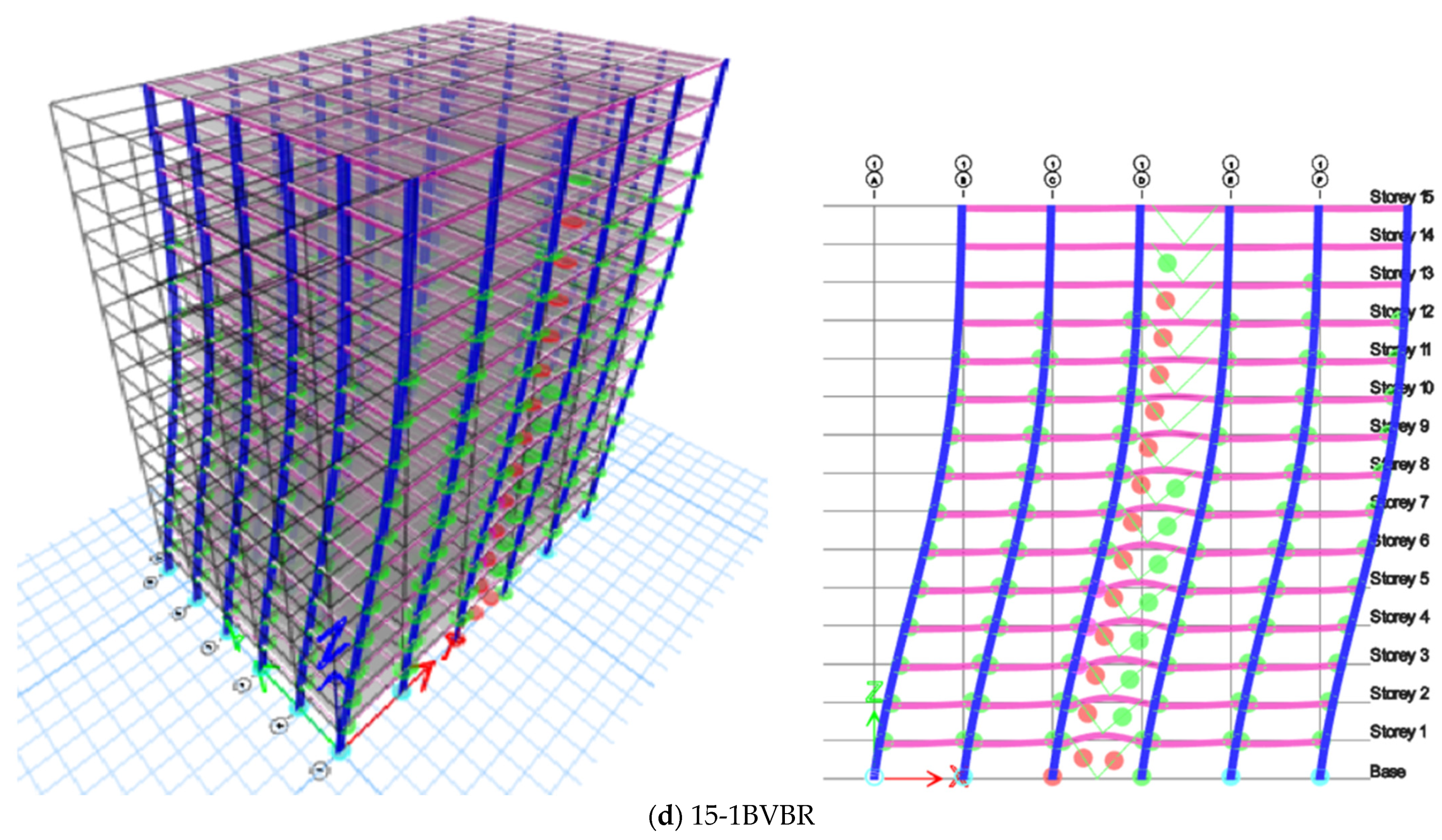
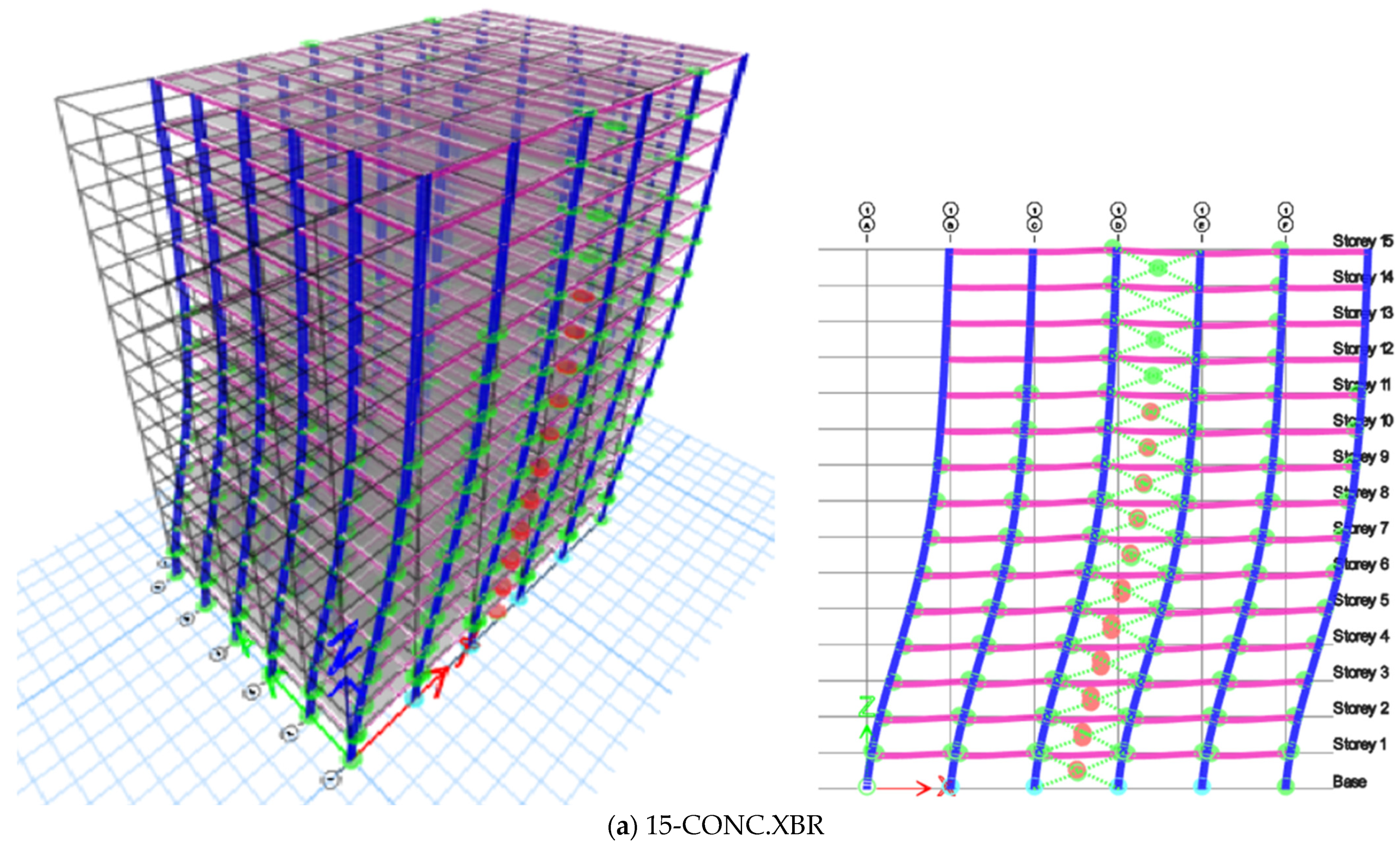
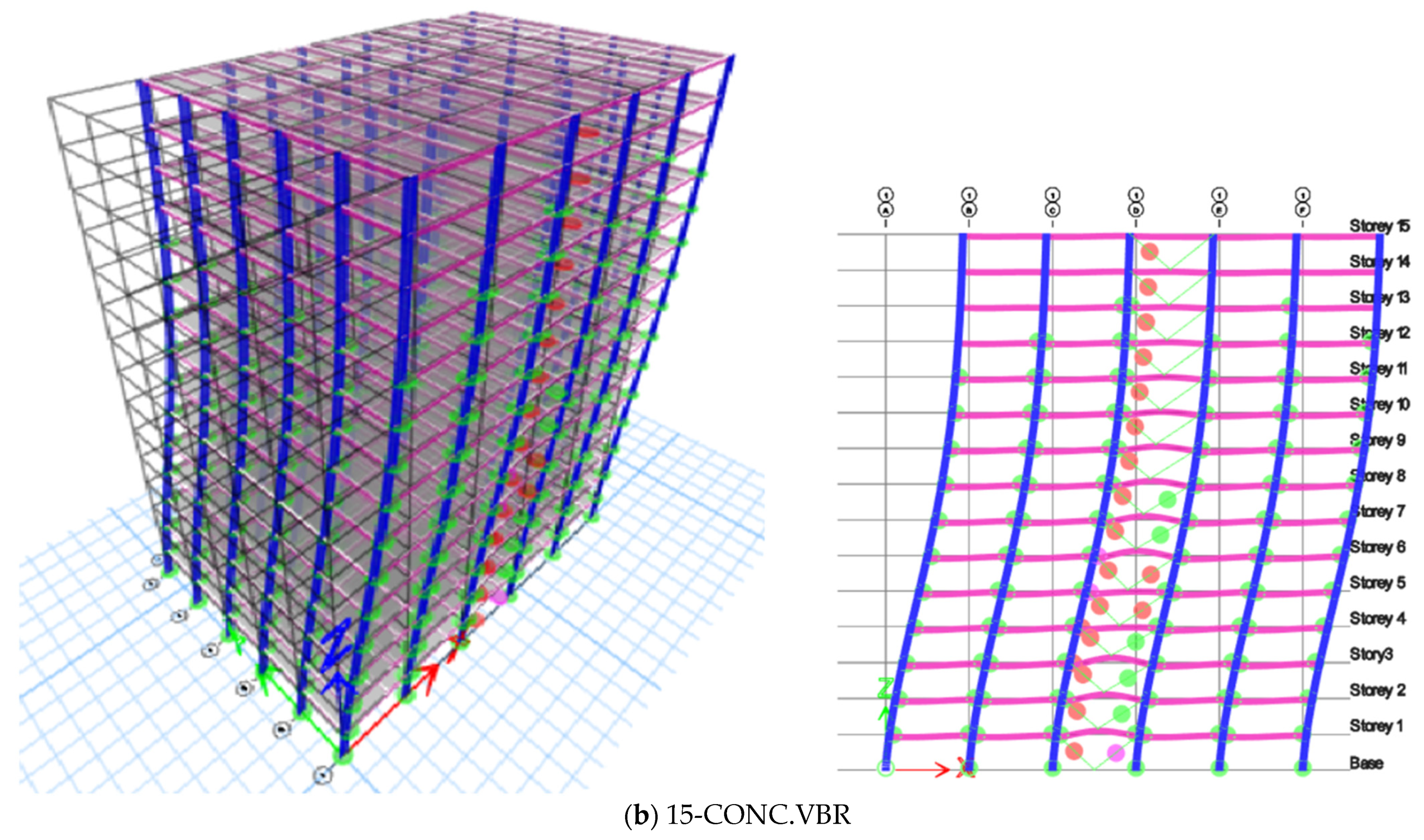
4. Plastic Hinge Formation
5. Concluding Remarks and Recommendations
- The length of the connections significantly influences the performance of V-braced frames compared to X-braced frames.
- The categorization of eccentric connections as either shear or intermediate links plays a pivotal role in determining the structure’s lateral displacement and energy dissipation.
- The column link length of 0.5 m showed a stiffness reduction of 5% when compared with the beam link of the same length. However, when the number of stories increased, the difference was less than 1%. Additionally, when the column link length is increased to 1.0 m, the stiffness reduction is increased by 15% in low-rise buildings and <5% in high-rise buildings.
- The eccentric X-braced frames are stiffer when compared with the V-braced frames when the link is in the beams. When the links are in the columns, the V-braced frames are stiffer than the X-braced frames.
- In the case of column links, lateral deformation is observed to be approximately 10% greater than that of beam links but 30% less than in moment-resisting frames (MRFs), consistently falling within the recommended displacement limits specified by ATC 40 and AISC 341.
- The lateral deformation of the MRF is controlled by braced frames, and X-braced frames offer more stiffness against lateral deformation compared with V-braced frames. The EBF with a link beam and link column is not effectively utilized in low-rise buildings. The 1.0-m eccentric link column in V-braced frames can be used for better performance in high-rise buildings when compared with the 1.0-m link beam in V-braced and X-braced frames.
Author Contributions
Funding
Data Availability Statement
Conflicts of Interest
References
- Alonso-Rodríguez, A.; Tsavdaridis, K.D. Effect of Rotational Inertia on Building Response to Earthquakes via a Closed-Form Solution. Mech. Based Des. Struct. Mach. 2021, 51, 1842–1855. [Google Scholar] [CrossRef]
- Tabar, A.M.; Alonso-Rodriguez, A.; Tsavdaridis, K.D. Building Retrofit with Reduced Web (RWS) and Beam (RBS) Section Limited-Ductility Connections. J. Constr. Steel Res. 2022, 197, 107459. [Google Scholar] [CrossRef]
- Boushehri, K.; Tsavdaridis, K.D.; Cai, G. Seismic Behaviour of RWS Moment Connections to Deep Columns with European Sections. J. Constr. Steel Res. 2019, 161, 416–435. [Google Scholar] [CrossRef]
- Wang, Z.; Tsavdaridis, K.D. Optimality Criteria-Based Minimum-Weight Design Method for Modular Building Systems Subjected to Generalised Stiffness Constraints: A Comparative Study. Eng. Struct. 2022, 251, 113472. [Google Scholar] [CrossRef]
- Nassani, D.E.; Hussein, A.K.; Mohammed, A.H. Comparative Response Assessment of Steel Frames With Different Bracing Systems Under Seismic Effect. Structures 2017, 11, 229–242. [Google Scholar] [CrossRef]
- Hassanzadeh, A.; Gholizadeh, S. Collapse-Performance-Aided Design Optimization of Steel Concentrically Braced Frames. Eng. Struct. 2019, 197, 109411. [Google Scholar] [CrossRef]
- Rahimi, A.; Maheri, M.R. The Effects of Steel X-Brace Retrofitting of RC Frames on the Seismic Performance of Frames and Their Elements. Eng. Struct. 2020, 206, 110149. [Google Scholar] [CrossRef]
- Patil, D.M.; Sangle, K.K. Seismic Behaviour of Different Bracing Systems in High Rise 2-D Steel Buildings. Structures 2015, 3, 282–305. [Google Scholar] [CrossRef]
- Tengfei, L.; Su, M.; Sui, Y. Hybrid Simulation Tests of High-Strength Steel Composite K-Eccentrically Braced Frames. Steel Compos. Struct. 2021, 38, 1–15. [Google Scholar] [CrossRef]
- Montuori, R.; Nastri, E.; Piluso, V.; Pisapia, A. Design Procedure for Failure Mode Control of Linked Column Frames. Eng. Struct. 2023, 296, 116937. [Google Scholar] [CrossRef]
- Popov, E.P.; Malley, J.O. Design of Links and Beam to Column Connections for Eccenrically Braced Steel Frames. National Science Foundation and American Iron and Steel Institute: Washington, DC, USA; p. 1983.
- Yang, C.-S.; Leon, R.T.; DesRoches, R. Pushover Response of a Braced Frame with Suspended Zipper Struts. J. Struct. Eng. 2008, 134, 1619–1626. [Google Scholar] [CrossRef]
- Tong, G.S.; Pi, Y.L.; Bradford, M. Buckling Failure of an Unusual Braced Steel Frame Supporting an Electric Dust-Catcher. Eng. Fail. Anal. 2009, 16, 2400–2407. [Google Scholar] [CrossRef]
- Shayanfar, M.A.; Barkhordari, M.A.; Rezaeian, A.R. Experimental behaviour of cyclic behaviour of composite vertical links in eccentrically braced frames. Steel Compos. Struct. 2011, 12, 13–29. [Google Scholar] [CrossRef]
- Danesh, F.; Faridalam, M. Behavior of Link-to-Column Connections in Eccentrically Braced Frames. In Proceedings of the 15th World Conference of Earthquake Engineering, Lisboa, Portugal, 24–28 September 2012; p. 9. [Google Scholar]
- D’Aniello, M.; La Manna Ambrosino, G.; Portioli, F.; Landolfo, R. Modelling Aspects of the Seismic Response of Steel Concentric Braced Frames. Steel Compos. Struct. 2013, 15, 539–566. [Google Scholar] [CrossRef]
- Bouwkamp, J.; Vetr, M.G.; Ghamari, A. An Analytical Model for Inelastic Cyclic Response of Eccentrically Braced Frame with Vertical Shear Link (V-EBF). Case Stud. Struct. Eng. 2016, 6, 31–44. [Google Scholar] [CrossRef]
- Junda, E.; Leelataviwat, S.; Doung, P. Cyclic Testing and Performance Evaluation of Buckling-Restrained Knee-Braced Frames. J. Constr. Steel Res. 2018, 148, 154–164. [Google Scholar] [CrossRef]
- Mohammadrezapour, E.; Danesh, F. Experimental Investigation of Bolted Link-to-Column Connections in Eccentrically Braced Frames. J. Constr. Steel Res. 2018, 147, 236–246. [Google Scholar] [CrossRef]
- Kumar, M.S.; Senthilkumar, R.; Sourabha, L. Seismic Performance of Special Concentric Steel Braced Frames. Structures 2019, 20, 166–175. [Google Scholar] [CrossRef]
- Shoeibi, S.; Gholhaki, M.; Kafi, M.A. Simplified Force-Based Seismic Design Procedure for Linked Column Frame System. Soil Dyn. Earthq. Eng. 2019, 121, 87–101. [Google Scholar] [CrossRef]
- Yao, Z.; Wang, W.; Fang, C.; Zhang, Z. An Experimental Study on Eccentrically Braced Beam-through Steel Frames with Replaceable Shear Links. Eng. Struct. 2020, 206, 110185. [Google Scholar] [CrossRef]
- Kabir, H.; Aghdam, M. A robust Bézier based solution for nonlinear vibration and post-buckling of random checkerboard graphene nano-platelets reinforced composite beams. Compos. Struct. 2019, 212, 184–198. [Google Scholar] [CrossRef]
- Nguyen, D.D.; Nguyen, M.N.; Duc, N.D.; Rungamornrat, J.; Bui, T.Q. Enhanced Nodal Gradient Finite Elements with New Numerical Integration Schemes for 2D and 3D Geometrically Nonlinear Analysis. Appl. Math. Model. 2021, 93, 326–359. [Google Scholar] [CrossRef]
- Bert, C.W.; Malik, M. Differential Quadrature: A Powerful New Technique for Analysis of Composite Structures. Compos. Struct. 1997, 39, 179–189. [Google Scholar] [CrossRef]
- Šabatka, L.; Wald, F.; Kabeláč, J.; Kolaja, D.; Pospíšil, M. Structural Analysis and Design of Steel Connections Using Component-Based Finite Element Model. J. Civ. Eng. Archit. 2015, 9, 1–7. [Google Scholar] [CrossRef]
- Caprili, S.; Mussini, N.; Salvatore, W. Experimental and Numerical Assessment of EBF Structures with Shear Links. Steel Compos. Struct. 2018, 28, 123–138. [Google Scholar] [CrossRef]
- Erfani, S.; Vakili1a, A.; Akrami, V. Numerical Investigation on the Flexural Links of Eccentrically Braced Frames with Web Openings. Steel Compos. Struct. 2021, 38, 381–397. [Google Scholar]
- Li, T.; Shi, Q.; Wang, X.; Ye, C. Study on the Seismic Behavior of Eccentrically Braced Steel Frames of Replaceable Shear Links with Web Opening. J. Phys. Conf. Ser. 2020, 1637, 012036. [Google Scholar] [CrossRef]
- IS 1893:2016; Part-I-2016 Criteria for Earthquake Resistant Design of Structures, Part 1: General Provisions and Buildings. Bureau of Indian Standards: New Delhi, India, 2016; pp. 1–44.
- IS 875; Part 1 Code of Practice for Design Loads (Other than Earthquake) for Buildings and Structures. Part 1: Dead Loads-Unit Weights of Building Materials and Stored Materials (Second Revision). Bureau of Indian Standards: New Delhi, India, 1989.
- IS 875; Part 2 Code of Practice for Design Loads (Other than Earthquake) for Buildings and Structures, Part 2: Imposed Loads. Bureau of Indian Standards: New Delhi, India, 1987; p. 18.
- ETABS: Analysis and Design; Computer and Structure Inc.: Berkeley, CA, USA, 2018.
- IS:800; Indian Standard Code of Practice for General Construction in Steel. Bureau of Indian Standards: New Delhi, India, 2007.
- Naughton, D.T.; Tsavdaridis, K.D.; Maraveas, C.; Nicolaou, A. Pushover Analysis of Steel Seismic Resistant Frames with Reduced Web Section and Reduced Beam Section Connections. Front. Built Environ. 2017, 3, 59. [Google Scholar] [CrossRef]
- ATC-40; Seismic Evaluation and Retrofit of Concrete Buildings. Applied Technology Council: Redwood City, CA, USA, 1996.
- ASCE 41; Seismic Evaluation and Retrofit of Existing Buildings. ASCE: Reston, VA, USA, 2013; ISBN 9780784412855.
- Pekelnicky, R.; Hagen, G. A Summary of Significant Updates in ASCE 41-17. In Proceedings of the 2017 SEAOC Convention Proceedings, San Diego, CA, USA, 13–15 September 2017; Volume 1. [Google Scholar]
- AISC 341-16; Seismic Provisions for Structural Steel Buildings Supersedes the Seismic Provisions for Structural Steel Buildings. AISC: Chicago, IL, USA, 2016.
- EN 1993-1-8; Eurocode 3: Design of Steel Structures. CEN: Brussels, Belgium, 2011; Volume 8.
- EN 1994-1-1; Design of Composite Steel and Concrete Structures—Part 1-1: General Rules and Rules for Buildings Eurocode. CEN: Brussels, Belgium, 2011.
- Lin, X.; Okazaki, T.; Nakashima, M. Bolted Beam-to-Column Connections for Built-up Columns Constructed of H-SA700 steel. J. Constr. Steel Res. 2014, 101, 469–481. [Google Scholar] [CrossRef]


| General | Design Levels | Parameters Considered |
|---|---|---|
| Seismic Hazard | Soil Type | II |
| Seismic Zone | Zone-3, Zone-4 & Zone-5 | |
| Material | Structural Steel | Fe 345 |
| Grade of Concrete | M30 | |
| Reinforcement Steel | HYSD 550 | |
| Loading | Dead Load | Self-weight of the Steel Members & Concrete Slab and Flooring |
| Live Load | 3 kN/m2 | |
| Structure Modelling | Structure Model | SMRF with Dual System |
| 2a—Mode-1 | |||||||||||
| Type of Frame | MRF | CONC-XBR | CONC-VBR | 0.5 BXBR | 0.5 CXBR | 0.5 BVBR | 0.5 CVBR | 1.0 BXBR | 1.0 CXBR | 1.0 BVBR | 1.0 CVBR |
| No. of Stories | |||||||||||
| 5 | 1.15 | 0.57 | 0.74 | 0.6 | 0.63 | 0.81 | 0.76 | 0.65 | 0.77 | 0.92 | 0.9 |
| 10 | 2.3 | 1.38 | 1.61 | 1.42 | 1.45 | 1.72 | 1.63 | 1.47 | 1.63 | 1.88 | 1.74 |
| 15 | 3.47 | 2.32 | 2.57 | 2.36 | 2.39 | 2.7 | 2.58 | 2.42 | 2.58 | 2.9 | 2.71 |
| 2b—Mode-2 | |||||||||||
| Type of Frame | MRF | CONC-XBR | CONC-VBR | 0.5 BXBR | 0.5 CXBR | 0.5 BVBR | 0.5 CVBR | 1.0 BXBR | 1.0 CXBR | 1.0 BVBR | 1.0 CVBR |
| No. of Stories | |||||||||||
| 5 | 0.83 | 0.48 | 0.56 | 0.47 | 0.52 | 0.57 | 0.58 | 0.49 | 0.57 | 0.61 | 0.66 |
| 10 | 1.85 | 1.17 | 1.32 | 1.17 | 1.23 | 1.33 | 1.35 | 1.19 | 1.32 | 1.41 | 1.41 |
| 15 | 2.95 | 2 | 2.18 | 2 | 2.07 | 2.19 | 2.22 | 2.02 | 2.18 | 2.29 | 2.29 |
| 2c—Mode-3 | |||||||||||
| Type of Frame | MRF | CONC-XBR | CONC-VBR | 0.5 BXBR | 0.5 CXBR | 0.5 BVBR | 0.5 CVBR | 1.0 BXBR | 1.0 CXBR | 1.0 BVBR | 1.0 CVBR |
| No. of Stories | |||||||||||
| 5 | 0.8 | 0.35 | 0.45 | 0.36 | 0.39 | 0.48 | 0.47 | 0.38 | 0.46 | 0.55 | 0.55 |
| 10 | 1.8 | 0.87 | 1.03 | 0.89 | 0.92 | 1.09 | 1.05 | 0.92 | 1.04 | 1.21 | 1.14 |
| 15 | 2.79 | 1.53 | 1.71 | 1.54 | 1.58 | 1.78 | 1.73 | 1.58 | 1.71 | 1.93 | 1.83 |
| Link Length Considered | Classification |
|---|---|
| 0.5 m | Shear Link |
| 1.0 m | Intermediate Link |
Disclaimer/Publisher’s Note: The statements, opinions and data contained in all publications are solely those of the individual author(s) and contributor(s) and not of MDPI and/or the editor(s). MDPI and/or the editor(s) disclaim responsibility for any injury to people or property resulting from any ideas, methods, instructions or products referred to in the content. |
© 2023 by the authors. Licensee MDPI, Basel, Switzerland. This article is an open access article distributed under the terms and conditions of the Creative Commons Attribution (CC BY) license (https://creativecommons.org/licenses/by/4.0/).
Share and Cite
Reena G., C.; Gurupatham, B.G.A.; Tsavdaridis, K.D. Column Link Behavior in Eccentrically Braced Composite 3-Dimensional Frames. Buildings 2023, 13, 2970. https://doi.org/10.3390/buildings13122970
Reena G. C, Gurupatham BGA, Tsavdaridis KD. Column Link Behavior in Eccentrically Braced Composite 3-Dimensional Frames. Buildings. 2023; 13(12):2970. https://doi.org/10.3390/buildings13122970
Chicago/Turabian StyleReena G., Celine, Beulah Gnana Ananthi Gurupatham, and Konstantinos Daniel Tsavdaridis. 2023. "Column Link Behavior in Eccentrically Braced Composite 3-Dimensional Frames" Buildings 13, no. 12: 2970. https://doi.org/10.3390/buildings13122970
APA StyleReena G., C., Gurupatham, B. G. A., & Tsavdaridis, K. D. (2023). Column Link Behavior in Eccentrically Braced Composite 3-Dimensional Frames. Buildings, 13(12), 2970. https://doi.org/10.3390/buildings13122970