Article

Mind-Mapping Assessment of Reuse Potential of Glulam: An Experimental Study

1
Icam School of Engineering, Nantes Campus, 35 Av. du Champ de Manœuvres, 44470 Carquefou, France
2
Nantes Université, Ecole Centrale de Nantes, CNRS, GeM, UMR 6183, F-44600 Saint-Nazaire, France
3
Centre Scientifique et Technique du Bâtiment (CSTB), 77420 Marne-la-Vallée, France
4
Nantes Université, Ecole Centrale de Nantes, CNRS, GeM, UMR 6183, F-44000 Nantes, France
*
Author to whom correspondence should be addressed.
Buildings 2023, 13(12), 2929; https://doi.org/10.3390/buildings13122929
Submission received: 13 October 2023 / Revised: 16 November 2023 / Accepted: 19 November 2023 / Published: 24 November 2023
(This article belongs to the Section Building Materials, and Repair & Renovation)

Abstract

:
The goal of this work is to suggest a method for assessing the state of salvaged glued laminated timber and deciding whether it is appropriate for reuse. After conducting a thorough analysis of the wood pathology, a decision tree mind map was created. This was followed by the application of this methodology to evaluate a salvaged glulam frame obtained from a demolition site. To ensure the reliability of this approach, laboratory-based ex situ tests were carried out. A working protocol was established for obtaining a sample of the salvaged timber, and its characteristics were identified by examining the species, density, type of adhesive and its shear resistance, as well as the mechanical properties in the bending of both single and double laminates of timber. The results concluded that the glulam under investigation can be reused. The results revealed that the wood was spruce, with a density of 420 ± 45 kg/m3 under dry conditions. The glue used was melamine–urea–formaldehyde with a shear strength of 7.37 ± 1.79 MPa, which is below the standard threshold. The results of the bending strength and modulus of elasticity show that the single laminations and glulam are class C16 and class GL20H, respectively.

1. Introduction

The construction sector’s resource-intensive practices have significantly contributed to environmental degradation [1], but adopting a circular economy approach with the 3Rs (reduce, reuse, and recycle) can address this issue by minimising new production, improving waste management, and conserving energy [2,3,4]. Reusing products, equipment, and materials (PEMs) in construction happens to have promising potential [3] but has difficulties in meeting the requirements for new structures, as they may have altered during and since their previous use. This may be due to varying factors, such as exposure to different climatic conditions, which can cause visible damage, such as cracking, colour changes, increased permeability, swelling, and shrinkage [5,6]. Furthermore, reuse products may not conform to the same standards as the original installation, and a proper evaluation and assessment of their condition are necessary due to the lack of standardisation in the marking process [5]. Thus, assessing the condition of these materials can be difficult without the complete history of their alterations. This is especially true for older buildings without data on the original properties and material history. These points and their importance have been highlighted in various works [5,7,8].
Wood is widely used in the construction industry as solid wood or in the form of derived materials, such as glued laminated timber (GLT) and cross-laminated timber (CLT) [9]. Despite the advantages they offer in terms of geometry and strength, the heterogeneous and anisotropic natures of these materials, along with their varying physical properties under different environmental conditions, pose challenges in understanding their mechanical behaviour in structures [10]. GLT in particular is more complex than solid wood due to the adhesive that is added to the equation.
One of the main issues with salvaged wood products is the formation of cracks in structures, which can be caused by various stress-related mechanisms, such as external loading and internal stress, mainly initiated by swelling and shrinkage from moisture content variations [11,12]. Frese and Blaß [13] analysed a database of 550 damaged timber structures and cracks in the fibre direction in glulam, and cracks were responsible in about 70% of the cases. According to Dietsch and Tannert [11], on the damages occurring on glulam structures, cracks were the most encountered problems in about 46% of the 300 investigated glulam pieces.
As previously mentioned, the wood behaviour is significantly affected by its moisture content due to its hydrophilic and porous nature, allowing for moisture absorption. This absorption can be influenced by the presence or absence of wood treatments that enhance the hydrophobicity [14,15,16]. Wood treatments, such as heat treatment, may even alter the wood colour, providing a more uniform surface colour [17]. Additionally, chemical and preservative treatments commonly applied to the timber surface are used to improve its durability and can introduce various colours [18,19]. Moreover, moisture levels are also influenced by temperature and moisture fluctuations, which can lead to wood shrinkage and swelling [14]. These variations, in turn, may result in delamination and cracks, compromising the load-bearing capacity of glulam structures [12,20].
Martin et al. [21] have noted that various beetles and termites are common insects in Europe that can potentially harm glulam while it is in service [21,22]. They achieve this by burrowing into the wood and extracting their nourishment from it [23]. The likelihood of specific wood structures being targeted by insects that damage wood is influenced by various elements. These include the wood’s inherent composition, like its starch or extractive components, as well as external environmental factors, primarily humidity and temperature [21]. The larval stage is the most destructive stage for several types of insects [24]. Damage caused by insects can be mechanical or aesthetic and may not be visible on the surface. Exit holes, left by adult insects vacating their nests [18,20], can be used to identify the type of insect that caused the damage and can compromise the structural stability of the wood.
The discolouration of wood can be a sign of degradation and is linked to various factors, such as moisture gradients, exposure to UV light, temperature, and fungi [24]. According to Dinwoodie et al. [24], it is crucial to differentiate between fungi that cause wood rot, leading to timber decay, and those that merely feed on the cell contents, resulting in stains. The first group breaks down the cell wall components, causing woody tissue to fall apart, while the second group only consumes stored nutrients in the cell spaces, preserving the cell’s structure. Hence, fungi can cause both superficial and structural damage to the timber. The initial infection of the majority of wood-rotting fungi, as well as all sap-stain fungi in timber, is contingent upon the wood having a moisture content exceeding 20% [24]. Hence, high moisture is needed for the fungal proliferation and is followed by a rot that leads to a loss of mechanical resistance and even mass [25,26,27,28]. The optimal temperature conditions for most fungi typically range between 19 °C and 30 °C [24]. Two main types of timber-rotting fungi can be mentioned [29]: brown cubical rot and white rot. The former is caused by fungi that consume cellulose and hemicellulose, whereas the latter is caused by fungi that attack lignin, cellulose, and hemicellulos, the main components of the fibres, and lighten the colour of the wood. These decay and stain sources manifest in different degradation forms and colours [24]. In fact, the forms and colours of the fruit bodies of fungi, which are the visible mushroom parts, as well as those of their mycelia and hyphae, can be used to identify the rot type. The mycelium is the vegetative and destructive part of a fungus and hyphae are the fine tubes that constitute it. The distinction between them will be discussed later on.
It is important to note that, currently, there is no existing literature proposing a specific method to assess the reuse potential of glulam timber (GLT). However, there are several non-destructive and semi-destructive techniques [11,30] available today that can be utilised for the assessment of GLT, enabling the determination of various physical and mechanical properties. However, given the objective of assessing the reuse potential and conducting sampling, the development of a simplified and expedited assessment methodology would greatly facilitate the widespread adoption of GLT reuse. Consequently, the aim of this research was to develop an efficient in situ assessment protocol using a mind map approach that can effectively identify any anomalies previously mentioned. This protocol will serve as a diagnostic tool for evaluating the reuse potential of glulam timber. Based on the results obtained from this assessment, the subsequent mechanical and physical characterisation of glulam can be conducted through either destructive (DT) or non-destructive (NDT) testing methods.

2. Materials and Methods

2.1. Mind Map Approach Development

The on-site mind map approach is a structured process for primarily evaluating a material’s degradation state and making decisions about its reuse potential and requirements. The tool also offers the capability to examine the beams within an existing structure, identifying elements that may require replacement. The decision tree stands on an analysis of the state of the art, including potential degradation mechanisms, indicators, and testing methods. Visual observations of anomalies and defects lead to yes/no questions that determine whether defects are present. These questions include evaluations using basic non-destructive or semi-destructive testing methods. Based on the results obtained, conclusions are drawn regarding the state of the material and its suitability for reuse.
From the state of the art, three main titles were identified for the mind map: cracks, insects, and discolouration.

2.1.1. Cracks and Delamination

To assess the glued laminated timber cracks and delamination, it was agreed to use the recommendations of a document titled, written, and published by the French Federation of the Wood Construction Industry/SNBL—Technical Commission [31]. Given that delamination is defined in the document as the loss of structural integrity within the bonding joints of laminates, resulting in the appearance of cracks, the term “crack” is utilised henceforth to encompass both cracks in the timber and delamination in the glue line.
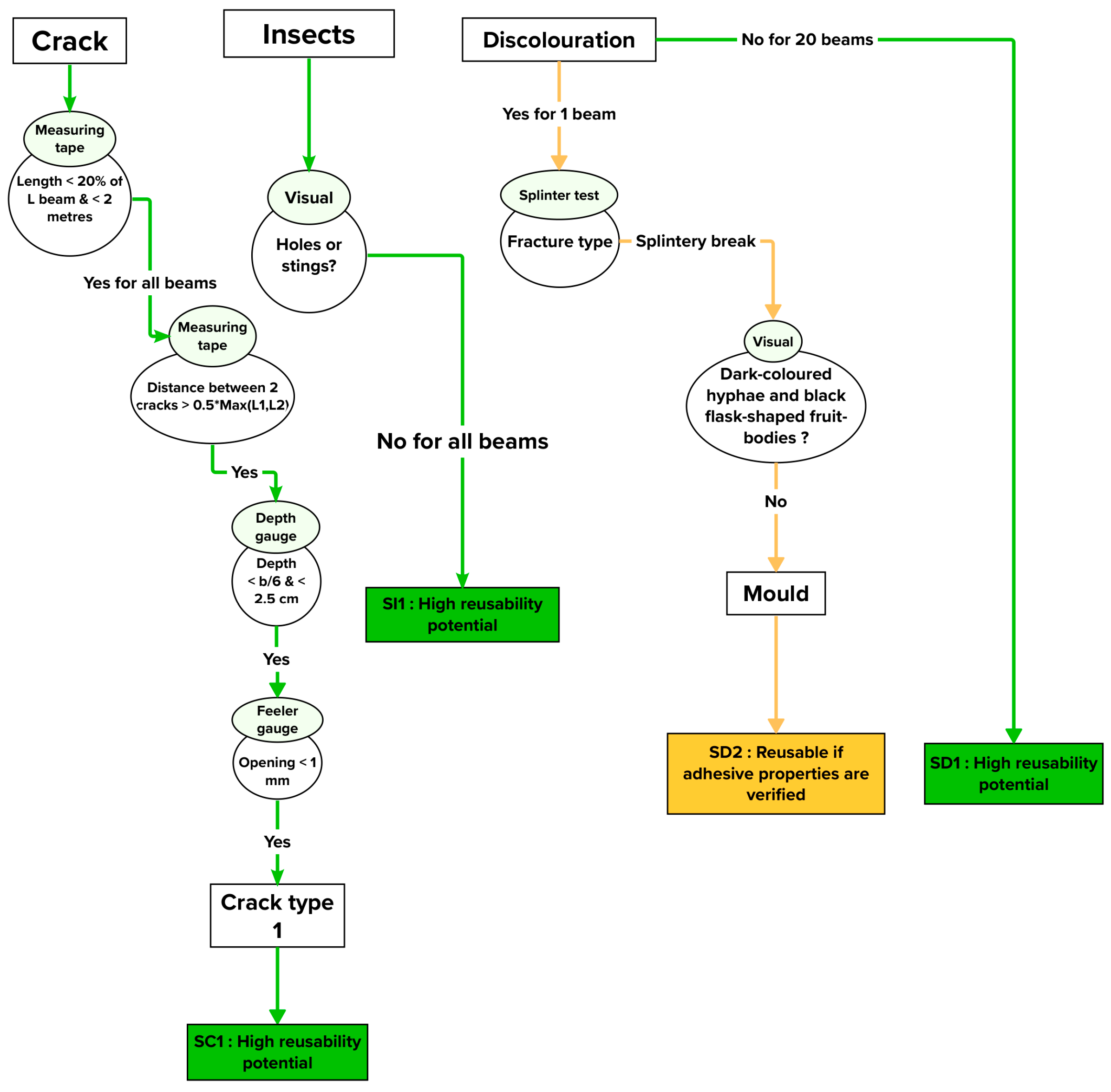
Cracks can be classified into three categories (Figure 1 describes the methodology and numbers of the scenarios) as follows:
-
Minor cracks with controllable locations. Minor cracks are defined as having limited impact and are distinguished by a depth that does not exceed 1/6 of the width “b” of the pieces. The maximum opening is 2.5 cm, with a length of around 2 m that does not exceed 20% of the length of the beam. These cracks can manifest in both the wood and bonding planes. In cases in which minor cracks are present on both sides of the beam, facing each other or in adjacent areas, their maximum depths should not exceed b/12. Minor cracks that are a few centimetres in length, a few millimetres in depth, and evenly spread over the entire height of the beam on both faces do not necessitate structural repairs. Cracks that are found on the edges of beams or posts and are within the width “b”, with the same attributes as the previous category, are also regarded as minor and can be treated similarly. It should be noted that the distance between any two cracks should be greater than half the length of the longer of the two cracks. Cracks of this type are referred to in Figure 2 as SC1 and are illustrated in Figure 1a;
-
Significant/insignificant cracks with the potential to worsen over time. Cracks falling under this category exhibit larger dimensions compared to the previous category and are oriented parallel to the bonding planes. The crack length is restricted to less than 1/4 of the beam’s length, with individual limitations of 3 m. The openings of these cracks should be less than 5 mm during dry periods, with a limit of 9 mm otherwise. The depth of the cracks must not exceed b/3, and in cases of multiple cracks, they should be separated by at least 5 elementary laminates. However, this category does not include cracks in assembly zones or at the notch. In instances in which significant or insignificant cracks are present on both sides of the beam, facing each other or in adjacent areas, the maximum depths of the cracks should not surpass b/6. Figure 2 designates cracks of this nature as SC2. It is essential to note that cracks in this category are anticipated to evolve and should be closely monitored over time. Overall, a comprehensive analysis of the crack’s origin and manufacturing conditions should be undertaken in order to limit its evolution. SC2 can be seen in Figure 1b;
-
Wider or through cracks. This category includes cracks that surpass the criteria of the previous classifications or ones that are caused by transverse tensile stress that extends over a considerable length. Additionally, this category includes cracks that propagate across multiple laminae. In Figure 2, these types of cracks are labelled as SC3.
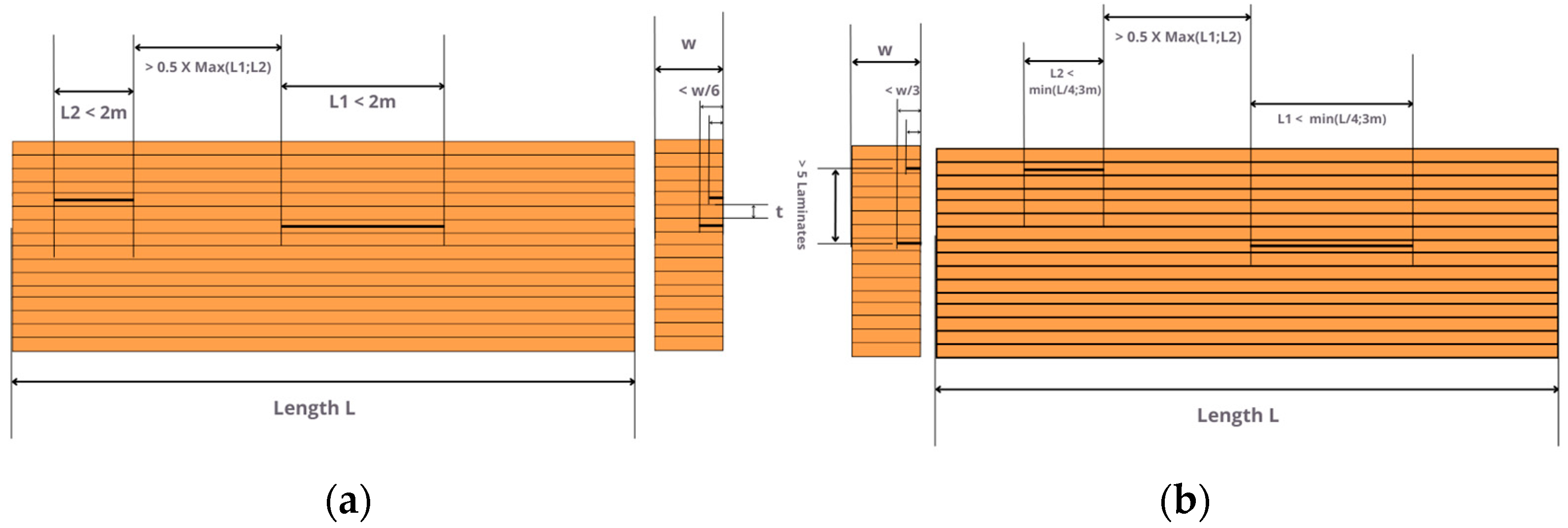
Figure 1. Illustration of crack criteria: (a) minor cracks; (b) significant/insignificant cracks.
Buildings 13 02929 g001
Note that a tape measure can be used for crack lengths, a depth gauge for the depth, and a feeler gauge for the crack opening or width. A depth gauge of a 0.2 mm thickness is suitable for measuring the depths of splits and cracks in wood [32].
Figure 2. Crack mind map methodology. SC stands for Scenario Crack.
Buildings 13 02929 g002

2.1.2. Insects

When inspecting laminated wood for the presence of insects, it is important to be aware of the signs of damage caused by wood-boring insects. The larvae, known as grubs, bore through the wood, forming a network of tunnels that are often filled with wood dust, referred to as “frass” [21,33]. Piles of frass on or beneath the infected wood serve as a clear indication that living insects are actively present. After completing their development as larvae, beetles emerge from the wood, leaving small round exit holes on the exposed surfaces. The sizes of these holes vary according to the species of the insect [34]. Illustrations of these damages can be seen in Figure 3.
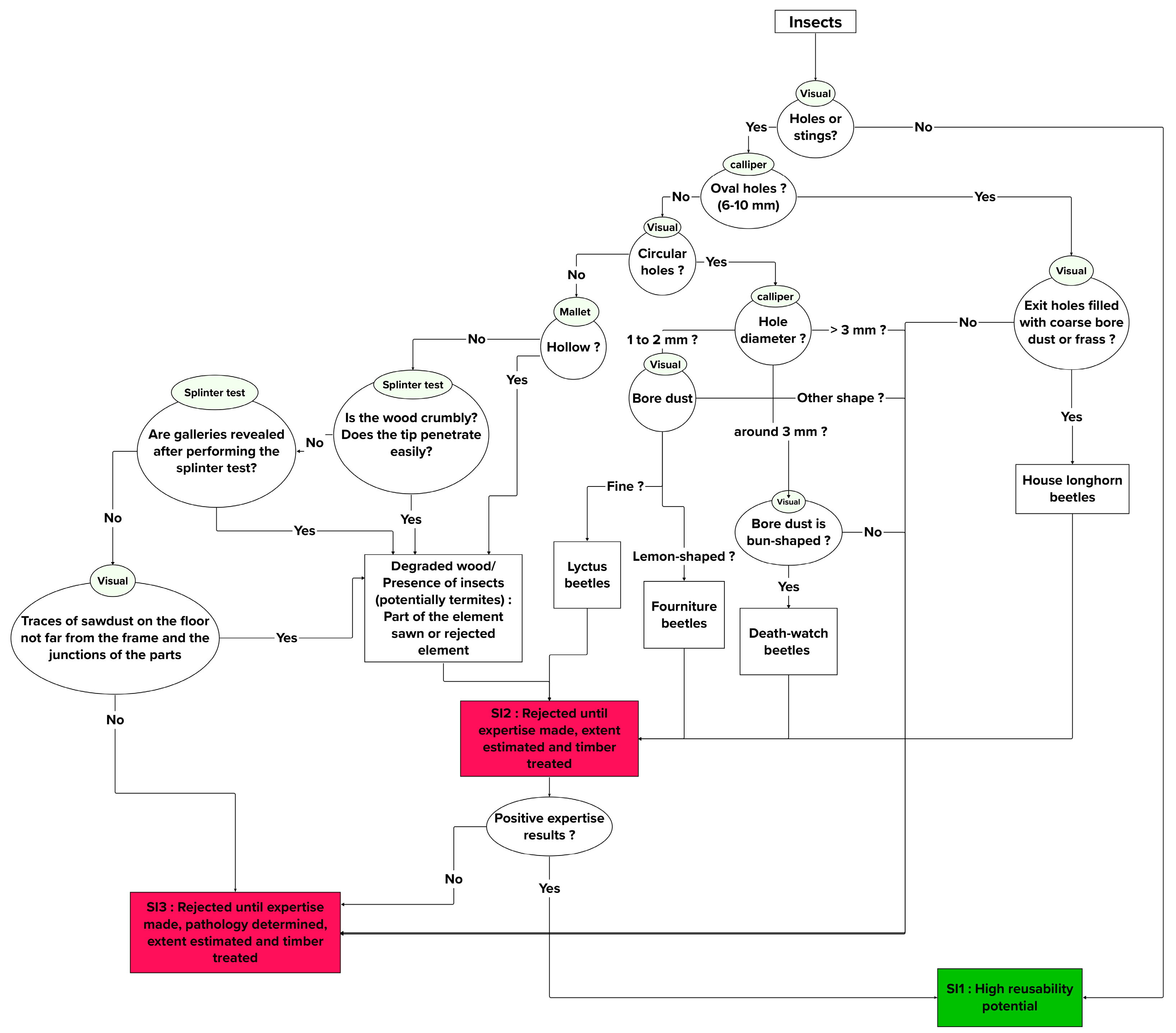
First, we will discuss the Cerambycidae, which are longhorn beetles. Generally, in the case of longhorn beetles, they are the larvae that cause damage by feeding on wood substances [24]. Typically, they leave behind oval-shaped holes filled with coarse bore dust or frass, ranging in diameter from 3 to 25 mm. While most longhorn beetles target green wood, an exception is the house longhorn beetle, which can infest building timbers [24,35]. For these beetles, the oval-shaped exit holes usually measure between 6 and 10 mm in diameter [35]. Beetles from the family Cerambycidae, such as the furniture beetle (Anobium punctatum) and the death-watch beetle (Xestobium rufovillosum), can impact wood [21]. The larvae of furniture beetles cause damage, leaving behind galleries filled with a granular frass that has a gritty texture when felt between the fingers [24]. These types of beetles primarily target the sapwood of both softwoods and European hardwoods, producing lemon-shaped bore dust pellets [36]. The resulting exit holes are circular, measuring approximately 1–2 mm in diameter [36]. Conversely, death-watch beetles infest both the sapwood and heartwood of partially decayed hardwoods. Their bore dust is bun-shaped, and they create circular exit holes around 3 mm in diameter [36]. Additionally, the Lyctus beetles from the Bostrichidae family, commonly referred to as powder-post beetles, can affect timber in use. They are restricted to the sapwood of hardwoods, producing fine bore dust and circular holes that are from 1 to 2 mm in diameter [36].
Termites pose a significant threat to timber structures, causing more annual damage than all other insect pests combined, as noted by Dinwoodie et al. [24]. Termites that target wood are categorised into two types: subterranean and dry-wood termites. Dry-wood termites typically feed just beneath the wood’s surface, predominantly on the sapwood. They generate a granular dust that is noticeably coarser than the dust produced by furniture beetles. This dust becomes visible when the undamaged wood surface is disrupted and is often expelled through the exit holes, acting as the primary sign of an active infestation. Subterranean termites maintain continuous sheltered pathways and progressively fill the cavities with mud as their attack advances. In this case, to further assess the wood, a mallet test can be conducted. By tapping the wood with a mallet, one can determine whether the wood is hollow. If so, it may indicate the presence of termites. Hence, a hollow sound upon the mallet test should lead to the immediate rejection of the wood. If none of these cases are present, then the splinter test is performed to assess the wood condition [37]. A sharp screwdriver or knife is inserted into the wood at a sharp angle and then bent. The goal is to assess the ease of penetration, which can be linked to the presence of porosity. Also, because dry-wood termites feed beside the surface, this test could expose their galleries. If the results are negative, unless an expert is consulted to assess the extent of the damage and determine whether there are still unaffected parts of the wood, then the element should not be reused.
Note that a calliper is used to measure the hole diameter and a screwdriver is used for the splinter test. The scheme is presented in Figure 4.

2.1.3. Discolouration

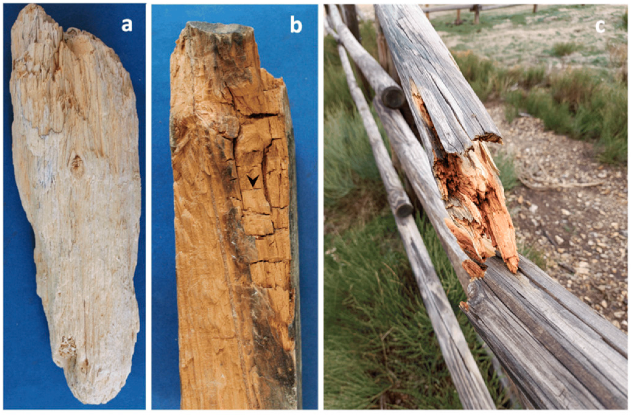
As stated before, different types of fungi exist and can cause serious damage to timber in general, as shown in Figure 5. Generally speaking, if the colour appears relatively consistent across the surface, then a chemical, thermal, or preservative treatment could be the cause, necessitating chemical analysis to identify its nature. However, it is unlikely that it is a form of degradation. Apart from this, when examining glulam for discolouration, the first step, as shown in Figure 6, is to perform a splinter test on the discolouration zone [37]. The characteristics of the resulting fracture in the extracted splinter are analysed. If the fracture appears splintered, then this indicates that the wood is sound. Afterwards, if the discolouration is not easily penetrated or the timber seems softened and the wood’s translucent cells contain many dark-coloured hyphae that are not just on the surface, then this often results in a visible tint on the exterior, signifying a blue stain [24]. This has black flask-shaped fruit bodies. If not, it is likely mould. In both cases, the properties of the glue should be verified, as the mechanical properties of the wood are not affected [38]. In contrast, if the fracture appears breached, then it may indicate reduced strength and the presence of decay.
In such situations, the wood’s appearance is assessed for its colour based on the guidelines provided by Iliston et al. [36]. If the wood displays a pale (or bleached) hue and becomes fibrous in texture, then it is probably affected by white rot. If this is not the case, then one should check whether the wood exhibits a dark shade and has cracks in three dimensions, forming somewhat uniform cubes. If these characteristics are present, then they likely indicate brown rot. Furthermore, by closely examining the shapes and colours of the mycelium, hyphae, and fruit body, and referencing Table 1, one can more accurately identify the specific type of fungus.
Figure 5. Wood damage by fungi: (a) fibrous appearance indicative of white rot; (b) cracks formed by brown-rot fungi; (c) severe deterioration in a wooden railing by brown-rot fungi. (Readapted with permission from Ref. [21]. 2023, Martín J.A. and López R.).
Buildings 13 02929 g005
If the wood has any of the mentioned types of rot, then it is necessary to assess the extent of the damage. If the damage is significant and most of the beam is already affected, then the wood is rejected because this will greatly impact its mechanical properties. If the damage is not severe, then the infected part is cut off, and the remaining wood is treated to ensure that the rot has been eliminated. Afterward, the properties of the wood and the adhesive are examined, depending on the case, to ensure they meet the required mechanical strength standards. If none of these situations apply, then the wood is rejected temporarily until a study can be conducted to determine the nature of the rot and its effects on both the wood and the bonding.
Figure 6. Discolouration mind map methodology. SD stands for Scenario Discolouration.
Buildings 13 02929 g006
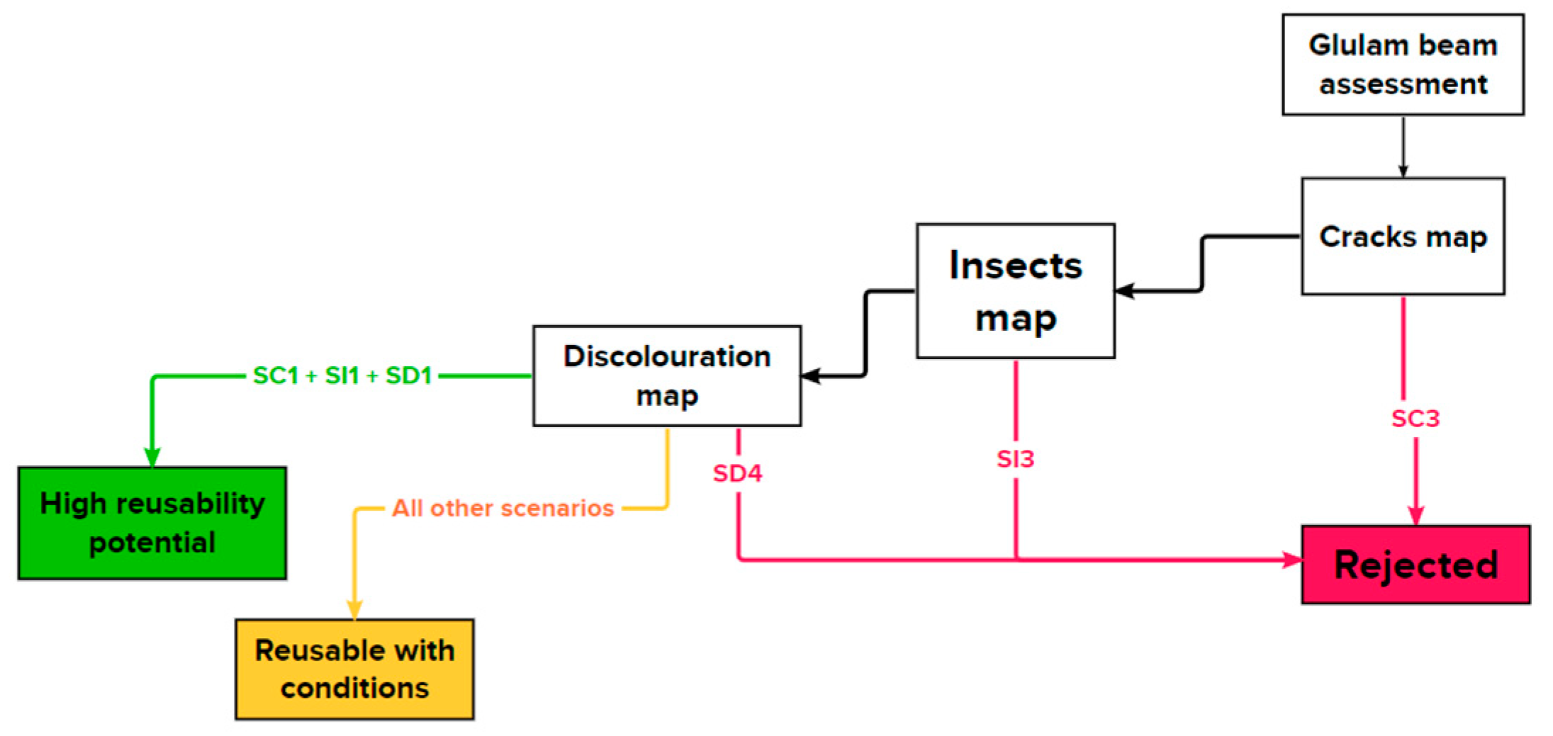
Figure 7 summarises the global steps of the mind map assessment methodology with the three main conclusions that can be encountered following the different scenarios. When the reuse potential is high or medium, a structural application is possible. Rejection does not necessarily imply that the beam should be immediately categorised as waste. A study can be conducted to determine whether it can be repurposed for other non-structural uses or recycled to manufacture other wood products.

2.2. Case Study

A case study was conducted to apply the developed assessment mind map methodology. To do so, a visit was arranged to an old textile factory (Figure 8a) in Montaigu-Vendée, a western French commune, to assess the condition of its glulam beams. The factory comprises two symmetric frames, with each frame consisting of an outer curved beam and two connected beams on the interior (see Figure 8a,b). The beams had varying cross-sectional profiles, ranging from 34 lamellae in the largest section to 13 lamellae in the smallest (Figure 8a), and the lamellae were 2 cm thick and 10 cm wide. The selected part for testing is shown in Figure 8b. For the record, the construction year was estimated to 1984, according to the supplied archive plans. At the time of the visit, the beams had already been deposited and therefore were numbered according to their arrangement in the yard, as shown in Figure 8c.

2.3. Experimental Protocol

2.3.1. The Microstructural Observation

The wood species were identified through the observation of their microstructures using the Olympus BH2 Infinity 2 metallographic microscope. The samples were first cut with a band saw and then polished with a polishing machine, Jean Wirtz FT 250, using silicon carbide abrasive disks.

2.3.2. Density

For the determination of the density, the oven-dry method was followed [39]: 5 cubic wood samples of 1 cm3 were dried in an oven at 103 °C and were weighed twice a day until the mass stabilised, followed by storage in a silica desiccator to protect against humidity. Next, the samples’ densities were calculated using Archimedes’ method, which involves measuring the sample’s weight in air and then in fluid.

2.3.3. Fourier Transform Infrared Spectroscopy (FTIR)

To determine the type of adhesive used, Fourier Transform Infrared Spectroscopy (FTIR) was performed with the Perkin Elmer spectrometer. The transmission FTIR technique was employed to analyse the disparity in the transmission spectra between the wood and the adhesive combined with the wood. Notably, no sample preparation was conducted prior to the analysis.

2.3.4. Shear Tests

These tests were carried out on 32 specimens, using the electromechanical universal testing machine (Instron model 5566) with a 10 kN force cell. The samples were prepared according to the NF EN 302-1 standard [40]. The samples were bonded assemblies measuring 150 mm × 20 mm × 10 mm, with the glue line positioned at the midpoints of their thicknesses. Overlaps of 10.0 mm were created in the central sections. The samples were then stored, and the tests were conducted under ambient laboratory conditions (a temperature of ~23 °C and relative humidity between 55 and 65%). As for the test parameters, a constant speed of 0.12 mm/s was used, as the standard recommends a speed that allows the test to be completed in less than 90 s. The applied load data obtained afterward enabled the value of the shear strength to be deduced directly using Equation (1):
S t r e n g t h s h e a r M P a = M a x l o a d ( N ) 10 × 20 ( mm 2 )
Following the shear strength test, the wood failure percentage (WFP) for each tested specimen was visually estimated using a graded scale in 10% increments, in accordance with EN 302-1 recommendations.
Variations in the shear strength were then evaluated using a one-way ANOVA at a significance level of α = 0.05. Subsequently, the Tukey HSD test was employed, also at a significance level of α = 0.05, to compare the means across different sample sets for the shear resistance. This approach was also applied to the obtained values from the bending tests.

2.3.5. Bending Tests

Four-point bending tests were performed on 45 single laminates and 15 double laminates with the following dimensions: 20 cm × 100 cm × 380 cm and 40 cm × 100 cm × 760 cm. Two Instron models, 5566 and 5585, equipped with 10 kN and 200 kN force cells, respectively, were used, and the protocol extracted from the EN 408 standard [41] was followed. The samples were also stored in the laboratory, and the tests were conducted under ambient laboratory conditions.
The tests consist of positioning the sample between two lower supports (well centred), respecting the mentioned sample dimensions, before beginning. The maximum allowable rate of the loading head’s movement should not exceed 0.003 mm/s. Specifically, for single laminates and double laminates with their respective thicknesses (“h”), the average speeds are 0.06 mm/s and 0.12 mm/s. This is because of the variations in thickness that can be encountered, which is why a thickness measurement is made at three different points and a mean is taken for each sample.
After the strength and bending modulus are calculated, their values to the fifth percentile are determined according to NF EN 14,358 [42]. The values found are then divided by a scaling factor to correspond to the classification of EN 338 [43], which is performed with the help of a table based on the strength and modulus of elasticity at the fifth percentile. Finally, once the class of the single laminates is known, EN 14,080 [44] is used to derive the class of the glulam.

2.3.6. Sampling

For the experimental part, the sampling was performed on the basis of the mind map results. The effected beam was chosen to be characterised, as it contained the mouldy section. The goal was to characterise it assuming that its performance would be set to a minimum for the entire batch. In this way, the 9 m beam, located on the exterior side of the building, was provided in 3 m sections due to transportation and shipping constraints. Each one of the beam’s three sections was cut into three sub-sections (SSs), as shown in Figure 9. Note that the mouldy section is SS 2.1. The mechanical characterisations were carried out from top to bottom for each framed sub-section (SS), taking three individual laminates, a double laminate, and a sample for the adhesive shear tests, and repeating the process three times for each sub-section, as can be seen in Figure 9.

3. Results and Discussion

3.1. Mind Map Application

The methodology was applied on the 21 recovered beams. Table 2 summarises the diagnosis of the condition of the glulam batch and the detection of its anomalies.
Table 2. Completion of the inventory and application of mind map methodology.
Lot NumberDesignationNumber of PiecesObservationsMind Map Results
1External portals6Five visually sound glulam beams with some greyish water infiltration stains–discolouration (Figure 10a)
One beam with a mouldy zone (Figure 10b)
No major cracks
No major delamination
No insect holes
5 beams → SD1+SC1+SI1 → reusable; 1 beam → SC1+SD2+SI1 → reusable if adhesive mechanical properties are verified.
2Internal portals4Visually sound glulam beams
No major cracks
No major delamination
No insect holes
No significant discolouration
4 beams → SD1+SC1+SI1 → reusable
3Internal portals4Visually sound glulam beams
No major cracks
No major delamination
No insect holes
No significant discolouration
4 beams → SD1+SC1+SI1 → reusable
4External portals7Visually sound glulam beams with some greyish water infiltration stains
No major cracks
No major delamination
No insect holes
7 beams → SD1+SC1+SI1 → reusable
Figure 10. On-site visual observations: (a) surface water infiltration; (b) severe infiltration.
Buildings 13 02929 g010
Figure 11 shows the conclusions drawn from the mind maps and the conditions for reusing these glulam beams. Generally, the results show that none of the beams contained either type 2 or type 3 cracks or laminations leading to an SC1 reuse scenario. For the insects, no anomaly was observed, which means that the concluded scenario is SI1. However, for the discolouration part, it was found that, for 20 beams, only some traces of surface water infiltration (Figure 10a) were noted, and they can be considered as SD1. The traces were easily removable via cleaning. One exception contained significant stains of water infiltration and had a grey mouldy section, as shown Figure 10b. The splinter test showed that penetration was not easy, the fracture of the wood seemed splintered, and the stains were more surficial, which means it is an SD2 scenario. Also, delamination can be seen on the stained area but not on other locations. According to the mass plan provided by the owners, the mould might be linked to the presence of a heating system nearby or some water infiltration from the roof.
Using these results and basic information about the batch, different tests to be undertaken were identified. As a reminder, the goal of this work was to verify the mind map conclusions and to prepare a technical sheet of the product. Hence, the experimental protocol combined the required tests from the mind map (i.e., checking the adhesive mechanical properties and the lack of technical characteristics). Then, identifying the essential technical characteristics involved determining factors such as the wood species used, the bending strength, and the shear strength of the adhesive. For all the tests, it was necessary to study the variability in the properties along the beam. This is why from 3 to 5 samples, located at different positions, were taken for the tests to be performed in accordance with current standards.

3.2. Experimental Results

3.2.1. Wood Species

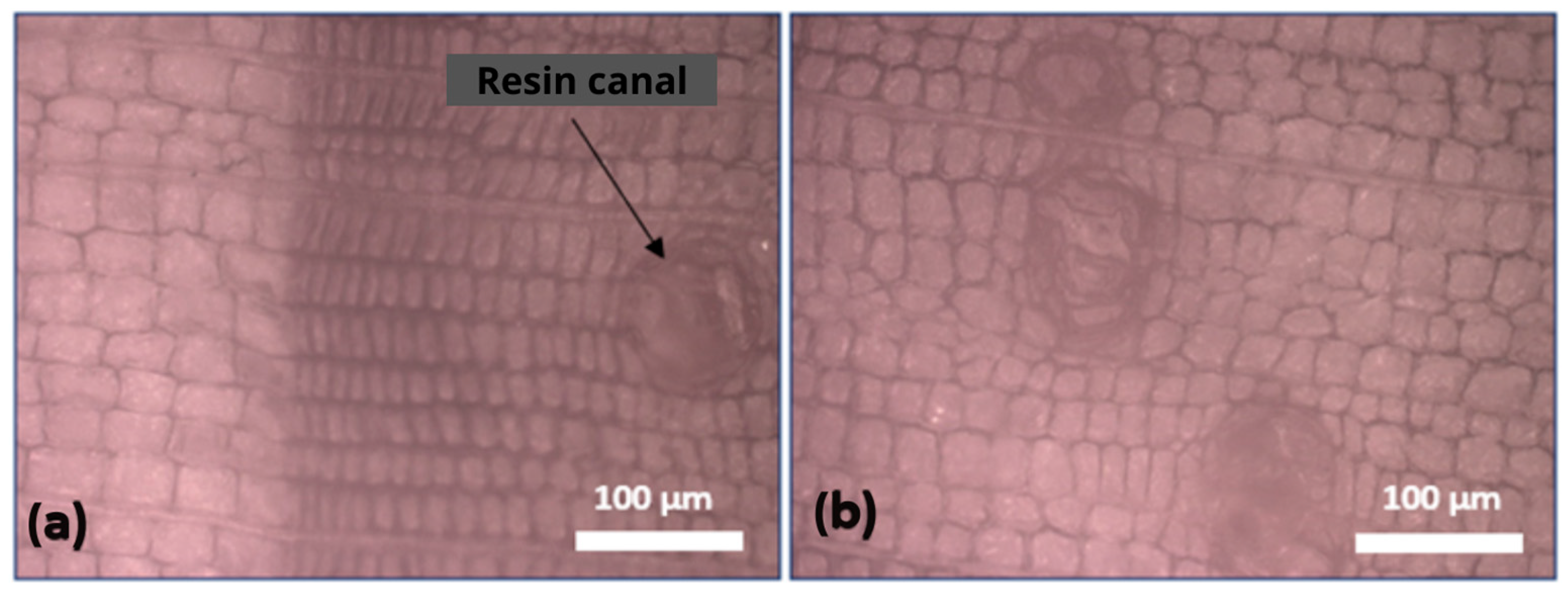
The species used for the beams was determined via microscopic observations of the cross section of the specimen. Figure 12a,b show a normal resin canal with a scalloped section on the observed surface. Because a gradual transition between earlywood and latewood is visible, the species is spruce [45,46].

3.2.2. Density

The resulting density is 420 ± 45 kg/m3. According to the literature, the density of spruce can vary between 370 and 571 kg/m3 [47] and is 450 kg/m3 [48] in France at a 12% moisture content. Considering that the sample was taken in dry conditions, the additional weight that this added, as well as the errors related to handling, could justify this deviation.

3.2.3. Adhesive Type

For the adhesive-type analysis using FTIR spectroscopy, Figure 13 presents two spectra: an adhesive mixed with wood and wood alone. It also highlights the principal peaks observed in each of them. Subsequently, through a comparative analysis with pertinent literature on the wood, the additional peaks specific to the adhesive could be discerned.
Indeed, the main peaks identified in the wood spectrum are indicated by the dashed, dotted, vertical lines in Figure 13 and are as follows [49,50]:
  • An absorption band of 3650–3000 cm−1, which is attributed to O-H stretching vibrations, indicating the presence of hydroxyl groups in the wood components, such as cellulose, hemicellulose, and lignin;
  • A peak detected at approximately 2900 cm−1, which is due to the asymmetric and symmetric C-H stretching of lignin, hemicellulose, and pectin;
  • A peak centred at 1740 cm−1, which corresponds to C=O stretching vibrations of the carboxyl and acetyl groups in hemicellulose;
  • A band at 1510 cm−1, which is due to the C=C stretching of the aromatic ring in lignin;
  • A band at 1372 cm−1, which is linked to CH bending in both cellulose and hemicellulose;
  • A peak centred at 897 cm−1, which represents the C-H vibrational mode in cellulose.
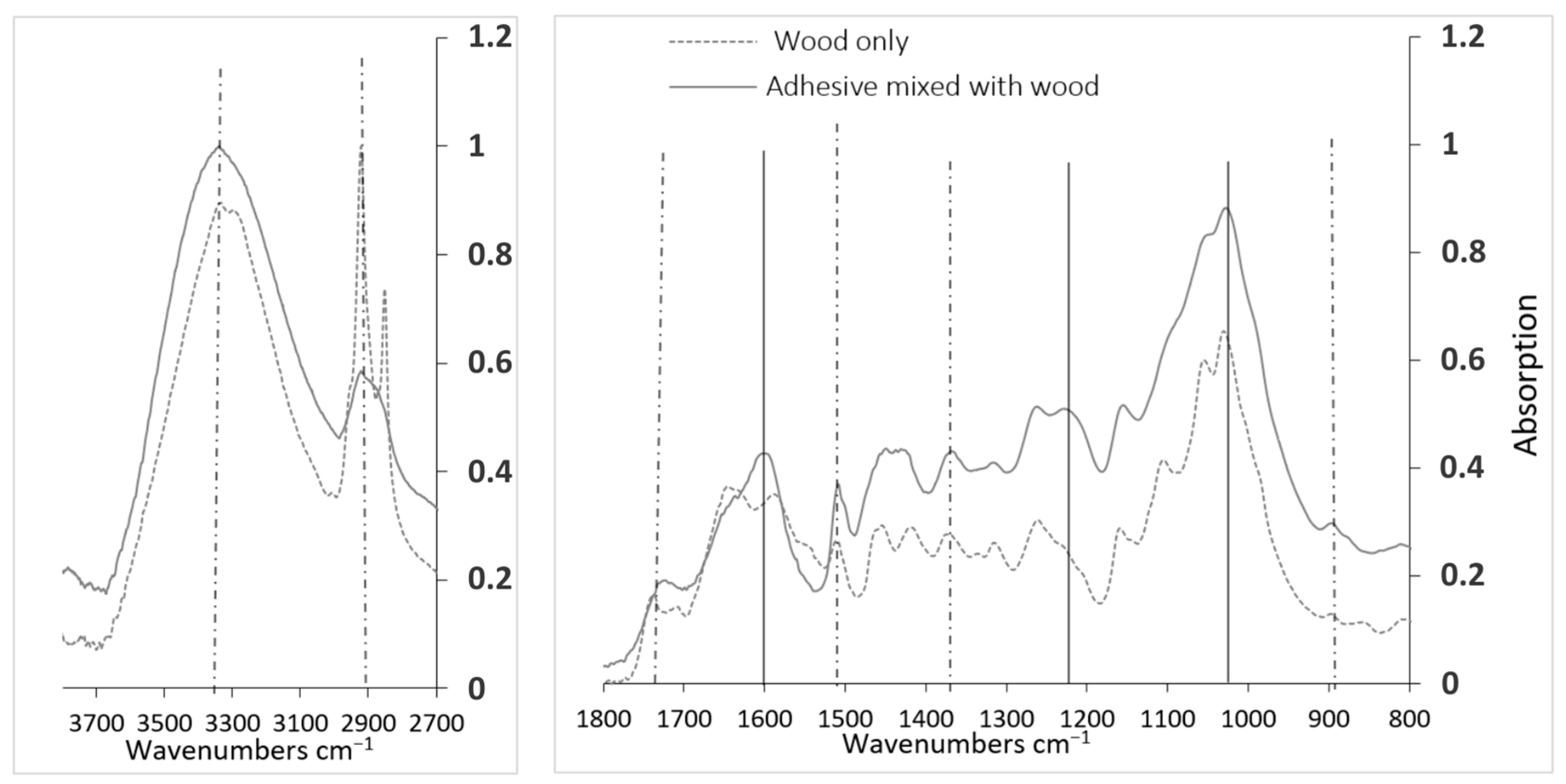
The spectrum of adhesive + wood exhibited some changes. Some peaks were added (indicated with solid vertical lines) and others were shifted (1740 cm−1). Specifically, the peaks at approximately 1600 cm−1, 1238 cm−1, and 1035 cm−1 can be ascribed to C=O, C-N, and N-H, respectively, and to the methylene bridge (–NCH2N–) [51]. These distinct chemical bonds correspond to the components intrinsic to MUF adhesive, associating them with the following peaks: peaks at 1600 cm−1 and 1238 cm−1 correlate with C=O and C-N and N-H in urea, respectively; peaks at 1238 cm−1 and 1035 cm−1 align with C-N and N-H and -NCH2N in melamine, respectively; the peak at 1632 cm−1 may also be linked to C=O in formaldehyde. In light of these findings, and considering its dark colour [52], attributed to natural aging, the adhesive can be classified as melamine–urea–formaldehyde (MUF).
Figure 13. Results and comparison of absorbance spectra of adhesive + wood and wood alone.
Buildings 13 02929 g013

3.2.4. Shear Strength of the Adhesive–Wood Bond

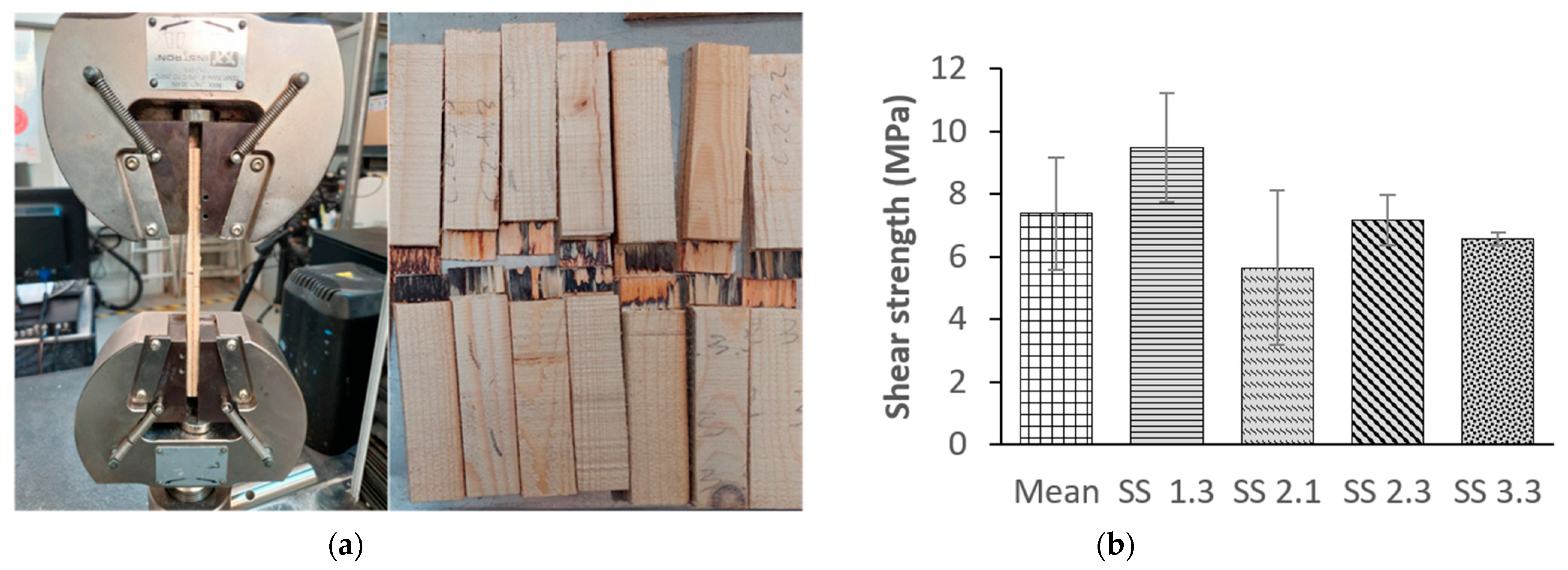
This part was delicate because out of the 32 tested specimens, only 18 produced usable results. This was due to the preparation of the specimens, which had to be cut up to the glue joint with high precision. The tested specimens before and after performing the test are illustrated in Figure 14a, and the testing results are presented in Figure 14b.
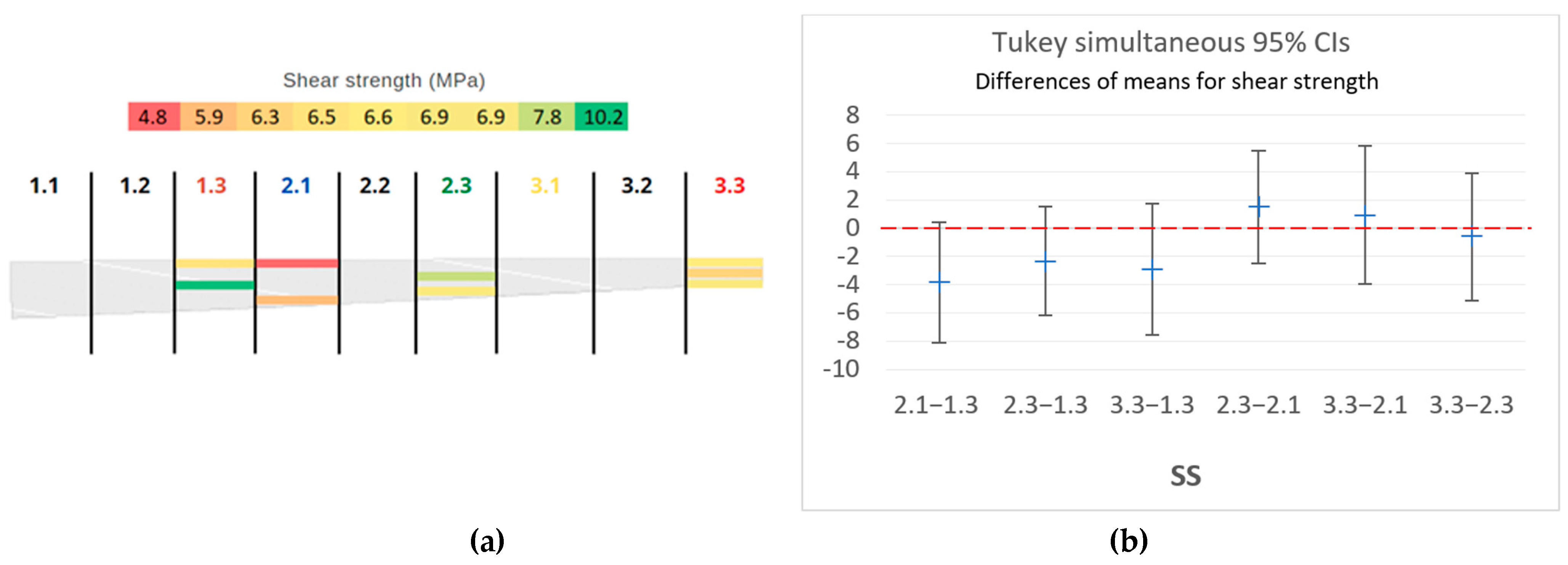
Shear tests were used to obtain the shear mechanical strength of the glue. The mean value of this strength for the entire beam was 7.38 ± 1.79 MPa, with a mean wood failure percentage of 64%. This last value is lower than the values of Wang X.A. and al. [53] for glulam blocks of MUF adhesive with spruce (86.6%), and the value is lower than the specified threshold (>72%) of the NF EN 14,080 standard [44]. It is noteworthy that the weakest results, which can be seen in Figure 15a, were recorded for SS 2.1, with a mean of 5.65 ± 2.45 MPa. More specifically, on the upper side (2.1.1), where the mould was noticeable, the strength was about 4.75 MPa. It is important to note that Figure 15b indicates that the observed variations are not statistically significant. By removing this mouldy SS, the mean value rose to 7.74 ± 0.55 MPa; thus, the deviation was reduced. The value is lower than 10 MPa, which is the threshold strength for new glulam structures given by the standard NF EN 302-1 [40] and in Tran’s works [54]. Therefore, it is necessary, a priori, to characterise the GLT.

3.2.5. Bending Test Results and Strength Class

Single Laminates
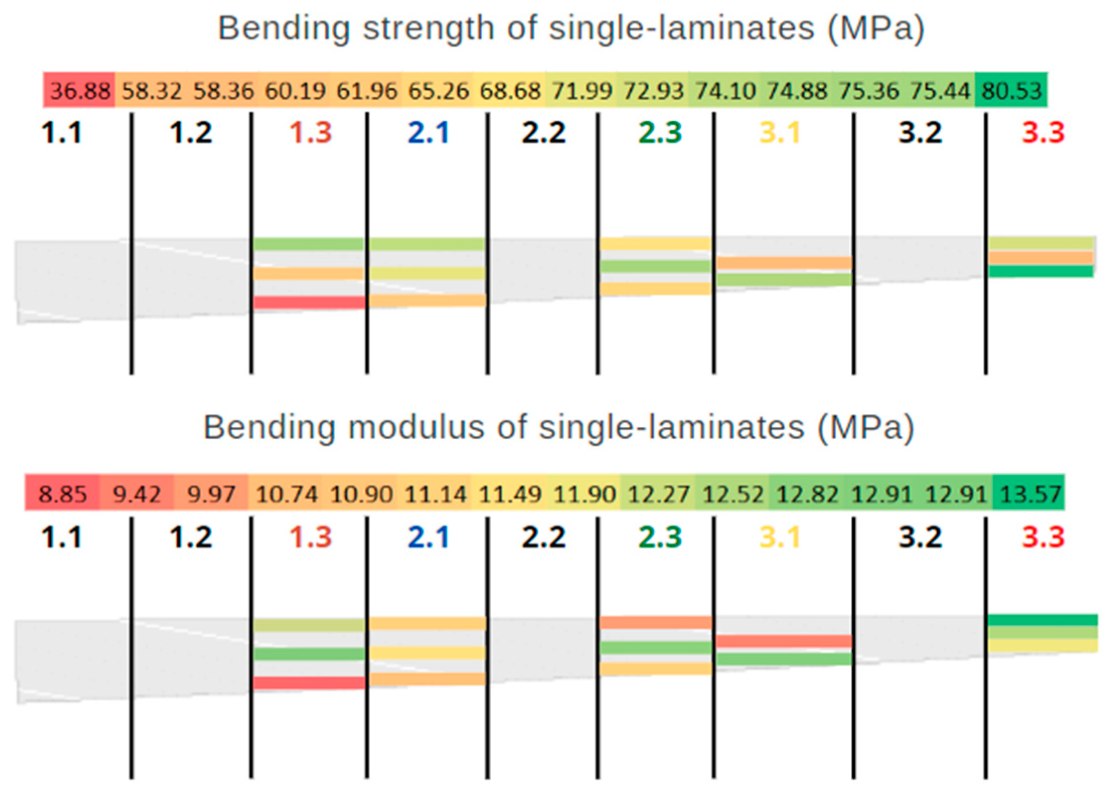
Figure 16 shows the bending strengths and bending moduli of the single laminates. In general, there are several types of wood failure, which include simple tension, transverse tension, splintering tension, strand tension, compression, and horizontal shear, as noted in [55]. The observed mode of breakage in the single laminates was transverse tension.
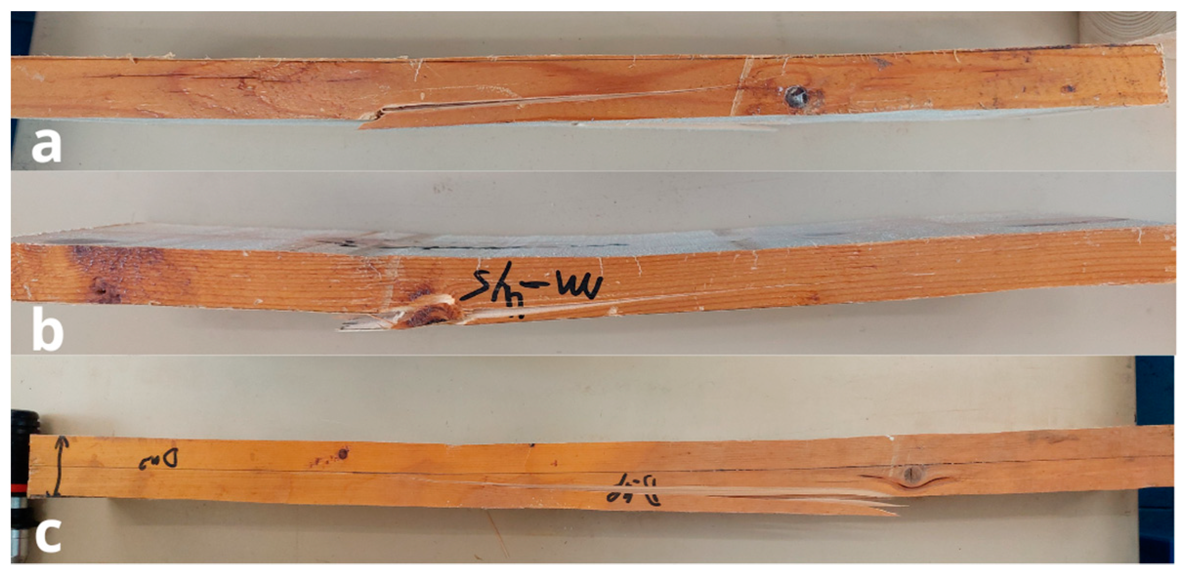
This transverse breakage in Figure 17a may be attributed to tension parallel to the grain in the lower portion of the laminate, which initiates the fracture at a point offset from the middle of the laminate. The origin of the defects or a combination of all these factors may also contribute to this type of failure.
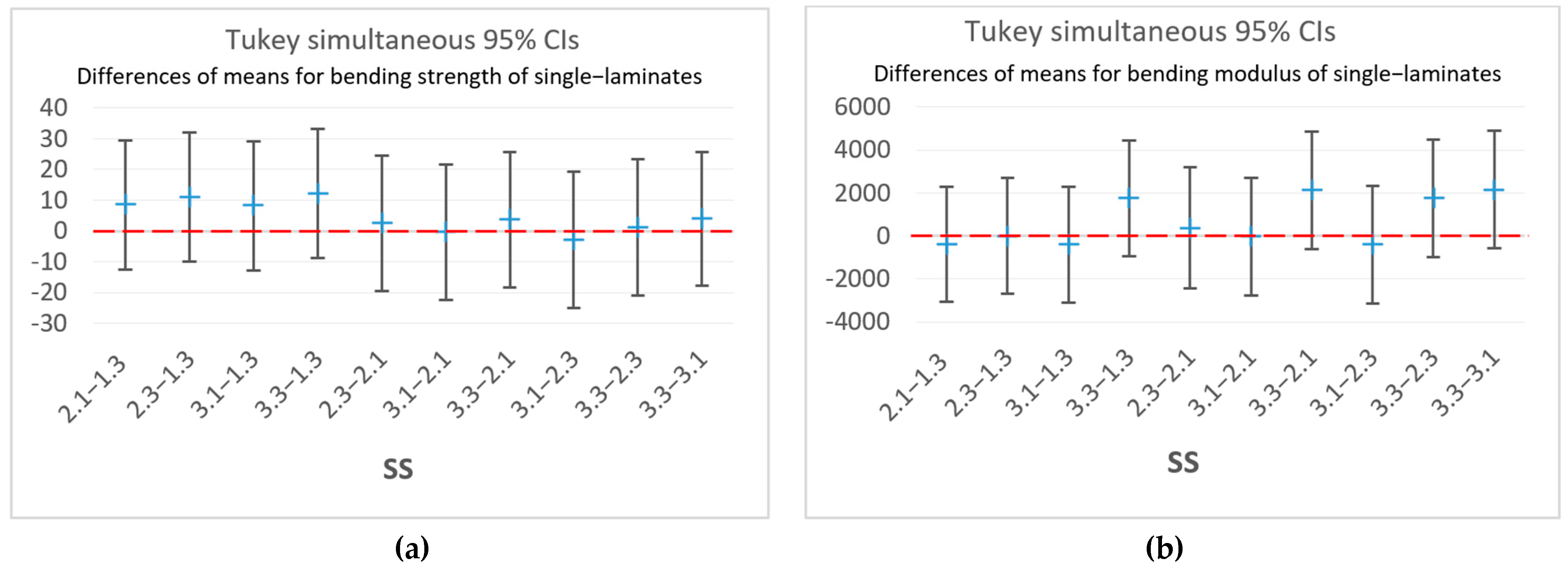
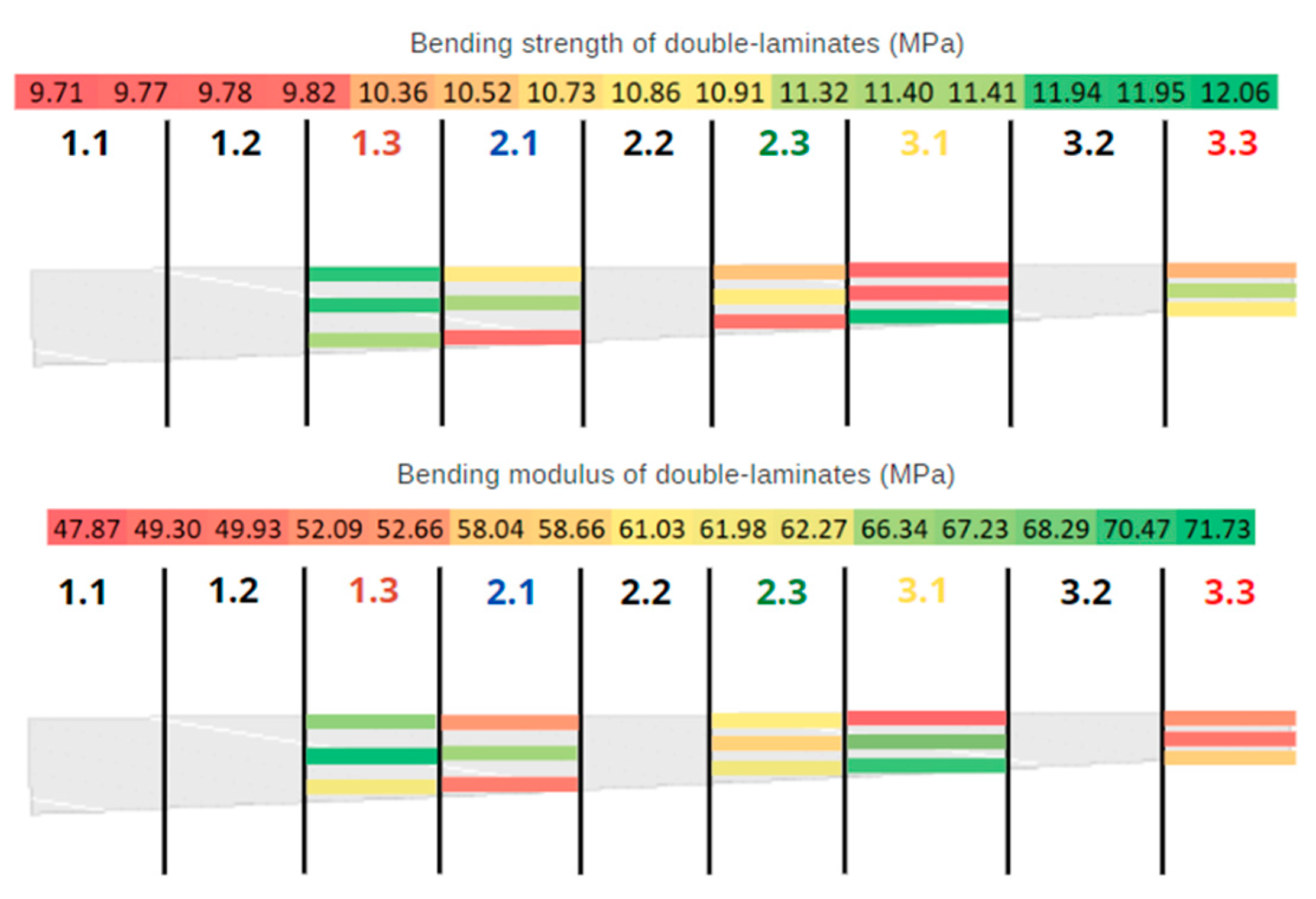
Statistical insignificance can be seen in Figure 18a,b for the bending strengths and moduli, respectively. The bending resistance was relatively stable and did not vary much along the beam, with a mean of 63.85 ± 12.25 MPa. The same is true for the modulus with a mean of 11.33 ± 1.45 GPa. This shows that there was some consistency in the bending performance, despite the existence of a mouldy area in SS 2.1. It shows that this apparent degradation only affected the adhesive properties. The maps in Figure 19 summarise the distribution of the recorded strengths and moduli along the beam. There are some regions where the resistance is lower than the rest, especially for SS 1.3 at the bottom (i.e., part 1.3.3). This is probably due to the presence of a knot (in Figure 17b) that weakened the piece [56] and thereby compromised the test.
Based on these values, it was possible to obtain the strength class of the wood according to the standard EN 338 [43]. To do this, the modulus and mechanical strength were calculated at the fifth percentile. The results obtained are 7 GPa for the modulus and 26 MPa for the strength. This strength corresponds to class C24 according to the standard’s table. However, the standard allows for this classification if the recorded modulus falls within the class. This is not the case, as 7 GPa is classified, rather, as C14, and, hence, the minimal class of this batch’s timber laminates is C14.
Figure 19. Map summarising the distribution of the bending properties of single laminates (in MPa for the strength and GPa for the modulus) along the beam.
Buildings 13 02929 g019

Double Laminates

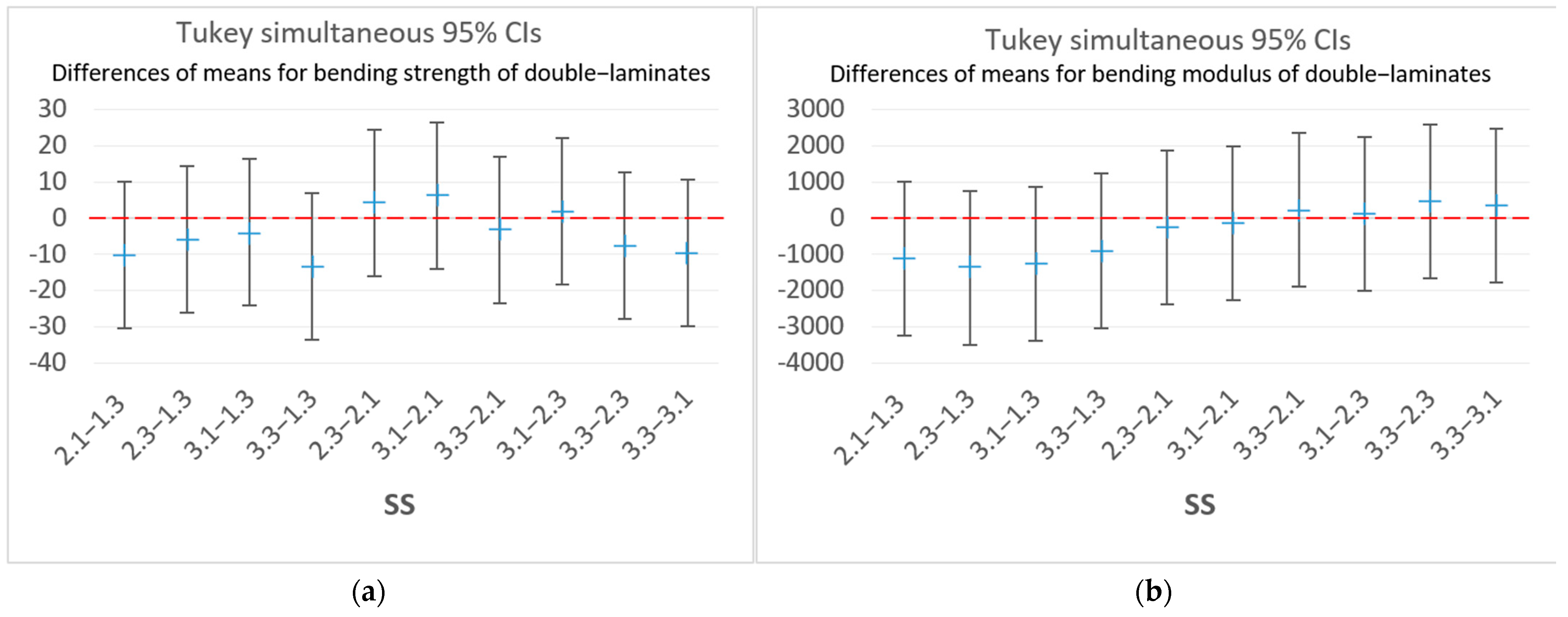
The same procedure was followed for the double laminates. The results are summarised in Figure 20. The resistance was relatively constant throughout the beam, with a mean of 59.79 ± 7.03 MPa. This was also found in the modulus at 10.62 ± 0.66 GPa, on average. The fracture mode observed for the double laminates is, for the lower laminate, the same as that of the single laminates studied earlier, except that, once the glue joint is reached, the crack spreads very quickly along its axis and the break occurs. Because the crack chooses the least energetic path, this could mean that the glue joint has a weaker resistance than that of the wood. The relatively low values of the shear strength of the glue could also confirm this. Figure 21 shows the variations in the properties along the beam. The low values can be linked to the presence of knots or defects (nail-fixing holes) that triggered the fracture of the double laminate faster. For instance, a knot may have contributed to the fracture of a specimen, as can be seen in Figure 17c. With regard to the mouldy part (SS 2.1), the values seem to be lower than those of the neighbouring sub-section (SS 1.3), which shows the effect caused by the poor adhesive properties. Statistical non-significance is evident in Figure 22a for the bending strength and in Figure 22b for the modulus.
Then, the calculation at the fifth percentile and the application of the EN 14,080 standard allowed for the obtainment of the mechanical class of the laminate (i.e., a GL20H design class based on the module and GL35H based on the mechanical resistance). Just like the reasoning to classify the single laminates previously, the retained classification is the lowest of the two, and, in this case, the beam is of the GL20H mechanical resistance class. According to Blank [57], a GL20H-class beam is made up of C16 class laminates, which shows agreement between the results for the single laminates and those for the double laminates. This class of glulam is suitable for structural purposes.
Figure 22. Graphical displays of pair-wise comparisons of SSs from Tukey’s HSD: (a) bending strengths and (b) modulus data of double laminates.
Buildings 13 02929 g022

4. Conclusions

The in situ assessment of glulam is a crucial step in ensuring the safety and performance of construction projects. It can optimise the evaluation and scaling process of reuse, supporting the goal of a circular economy. The mind map presented in this paper is a useful tool, as a first step, for determining the condition of the material, identifying potential visible defects, and proposing whether reuse is the best option.
The assessment was applied on a real case for the evaluation of the reuse potential of a batch of glulam beams, as well as for sampling. Its application showed that no important cracks or delamination were recorded in the batch, nor signs of insect presence. However, the discolouration map showed that the adhesive properties needed to be verified after finding mould. Also, the absence of technical information about the batch required its characterisation; thus, sampling was performed according to the mind map results. Subsequently, a methodology for the characterisation was developed and followed in order to study the variability in the selected beams. Several aspects of the beams were investigated, including the species, density, type of glue used with its shear strength, and bending properties in two stages (single and double layers). This allowed us to assign a strength class to the beams so that structural calculations could be performed to assess their suitability for a given structure. The main conclusions drawn from the experimental results are as follows:
  • The wood species was spruce, and its density was 420 ± 45 kg/m3 in the dry state;
  • The glue used in the glulam was melamine–urea–formaldehyde;
  • The shear strength of the glue was 7.37 ± 1.79 MPa, which is below the threshold allowed by the current standard;
  • For the single laminates, the mean bending strength was 65.85 ± 4.72 MPa, with 11.56 ± 0.80 GPa for the bending modulus, which were obtained after the calculations of the fifth percentile and using the scaling factor class C16;
  • For the double laminates, the mean bending strength was 59.79 ± 23.01 MPa, with a mean bending modulus of 10.62 ± 4.07 GPa;
  • The observed water infiltration (mould) on the beam had a strong influence on the properties of the glue, but not on the mechanical properties of the wood. This shows that the discolouration mind map conclusion was effective and led to the detection of this anomaly;
  • The values for the double laminates were lower than those for the single laminates, but still in the same range;
  • The comparison between the classes obtained from the Young’s modulus and bending strength indicated that the former was lower, leading to its adoption as the grading criterion for the GLT. This observation suggests that, for GLT reuse, emphasising the measurement of the modulus may be sufficient;
  • The glued laminated timber was of class GL20H, and this class corresponds to laminations of class C16;
  • During the different characterisations, no insect indications were found, which confirms the conclusion of the insect mind map;
  • Note that this method will be supported by NDT for internal defects in future works.

Author Contributions

Conceptualization, A.Y., M.N. and M.T.; methodology, A.Y., M.N. and M.T.; validation, M.N., M.T., A.K., C.R. and N.P.; formal analysis, A.Y., M.N. and M.T.; investigation, A.Y., M.N. and M.T.; resources, M.N., M.T., A.K., C.R. and N.P.; data curation, A.Y., M.N. and M.T.; writing—original draft preparation, A.Y.; writing—review and editing, A.Y., M.N., M.T. and A.K.; visualization, A.Y., M.N. and M.T.; supervision, M.N., M.T., A.K., C.R. and N.P.; project administration, M.N. and M.T.; funding acquisition, M.T. and C.R. All authors have read and agreed to the published version of the manuscript.

Funding

This research was funded by Region Pays de la Loire in France, funding number: AAP ECi 2021 convention n°2021_07249, and French Environment and Energy Management Agency (ADEME), funding number: 21PLD0477, as part of the project “Filière 3R: de l’expérimentation à la massification”.

Data Availability Statement

Data is contained within the article.

Conflicts of Interest

The authors declare no conflict of interest.

References

  1. Haeusler, L.; Guyot, M. Waste Key Figures: The Essentials 2020; ADEME: Angers, France, 2020. (In French) [Google Scholar]
  2. Minunno, R.; O’Grady, T.; Morrison, G.M.; Gruner, R.L. Exploring environmental benefits of reuse and recycle practices: A circular economy case study of a modular building. Resour. Conserv. Recycl. 2020, 160, 104855. [Google Scholar] [CrossRef]
  3. Viola, J.; Thomas, S. Re-Use of Building Components (RE-USE) Potential for Systematic Re-Use of Building Components in a Regional Context and Realisation of a Pilot Project; BBSR: Bonn, Germany, 2021. (In German) [Google Scholar]
  4. Ministry of Ecological Transition. Circular Economy; Ministry of Ecological Transition: Paris, France, 2020. [Google Scholar]
  5. Poncelet, F.; Vrijders, J.J. Technical Framework for Re-Used Materials: How Can the Technical Performance of Re-Used Materials Be Justified? CSTC: Brussels, Belgium, 2021; 47p. (In French) [Google Scholar]
  6. Grubeša, I.N.; Teni, M.; Krstić, H.; Vračević, M. Influence of freeze/thaw cycles on mechanical and thermal properties of masonry wall and masonry wall materials. Energies 2019, 12, 1464. [Google Scholar] [CrossRef]
  7. Reuse Toolkit: Material Sheets. Available online: https://vb.nweurope.eu/projects/project-search/fcrbe-facilitating-the-circulation-of-reclaimed-building-elements-in-northwestern-europe/news/reuse-toolkit-material-sheets/ (accessed on 16 April 2022).
  8. European Commission Proposal for a Regulation Laying down Harmonised Conditions for the Marketing of Construction Products, Amending Regulation (EU) 2019/1020 and Repealing Regulation (EU) 305/2011. Available online: https://ec.europa.eu/docsroom/documents/49315 (accessed on 30 August 2022).
  9. Wei, P.; Wang, B.J.; Li, H.; Wang, L.; Peng, S.; Zhang, L. A comparative study of compression behaviors of cross-laminated timber and glued-laminated timber columns. Constr. Build. Mater. 2019, 222, 86–95. [Google Scholar] [CrossRef]
  10. Vardanyan, E.R.; Akimov, P.; Khalvashi, M.; Eghiazar (Eds.) Contemporary Problems of Architecture and Construction. In Proceedings of the 12th International Conference on Contemporary Problems of Architecture and Construction (ICCPAC 2020), Saint Petersburg, Russia, 25–26 November 2020; CRC Press: London, UK, 2021. ISBN 978-1-00-317642-8. [Google Scholar]
  11. Dietsch, P.; Tannert, T. Assessing the integrity of glued-laminated timber elements. Constr. Build. Mater. 2015, 101, 1259–1270. [Google Scholar] [CrossRef]
  12. Berg, S.; Sandberg, D.; Ekevad, M.; Vaziri, M. Crack influence on load-bearing capacity of glued laminated timber using extended finite element modelling. Wood Mater. Sci. Eng. 2015, 10, 335–343. [Google Scholar] [CrossRef]
  13. Frese, M.; Blaß, H.J. Damage Analysis of Wooden Hall Supporting Structures; KIT Scientific Publishing: Karlsruhe, Germany, 2010; ISBN 978-3-86644-590-1. (In German) [Google Scholar]
  14. Jiang, J.; Du, J.; Li, H.; Mei, C.; Gong, X. Hydrophobicity improvement on wood for a better application of this bio-based material. Coatings 2022, 12, 1465. [Google Scholar] [CrossRef]
  15. Jiang, J.; Cao, J.; Mei, C. Microstructure, hydrophobicity and thermal stability of wood treated by silica/montmorillonite nanoparticle-stabilized pickering emulsion (I). Wood Sci. Technol. 2022, 56, 111–121. [Google Scholar] [CrossRef]
  16. Nziengui, P. Wood Cracking in a Variable Climate under Long-Term Loads: Applications to European and Gabonese Wood Species. Ph.D. Thesis, University of Clermont Auvergne, Clermont-Ferrand, France, 2019. (In French). [Google Scholar]
  17. Gaff, M.; Kubovský, I.; Sikora, A.; Kačíková, D.; Li, H.; Kubovský, M.; Kačík, F. Impact of thermal modification on color and chemical changes of African padauk, merbau, mahogany, and iroko wood species. Rev. Adv. Mater. Sci. 2023, 62, 20220277. [Google Scholar] [CrossRef]
  18. Ayanleye, S.; Udele, K.; Nasir, V.; Zhang, X.; Militz, H. Durability and protection of mass timber structures: A review. J. Build. Eng. 2022, 46, 103731. [Google Scholar] [CrossRef]
  19. Groenier, J.S.; Lebow, S. Preservative-Treated Wood and Alternative Products in the Forest Service; Forest Service, Technology & Development Program: Missoula, MT, USA, 2006; 44p. [Google Scholar]
  20. Gaspar, F.; Cruz, H.; Gomes, A. Modeling the influence of delamination on the mechanical performance of straight glued laminated timber beams. Constr. Build. Mater. 2015, 98, 447–455. [Google Scholar] [CrossRef]
  21. Martín, J.A.; López, R. Biological deterioration and natural durability of wood in Europe. Forests 2023, 14, 283. [Google Scholar] [CrossRef]
  22. Verbist, M.; Branco, J.M.; Nunes, L. Characterization of the mechanical performance in compression perpendicular to the grain of insect-deteriorated timber. Buildings 2020, 10, 14. [Google Scholar] [CrossRef]
  23. Creffield, J.W. Wood Destroying Insects: Wood Borers and Termites; Csiro Publishing: Clayton, Australia, 1996; ISBN 978-0-643-10291-0. [Google Scholar]
  24. Desch, H.E.; Dinwoodie, J.M. Timber Structure, Properties, Conversion and Use; Macmillan Education: London, UK, 1996; ISBN 978-0-333-60905-7. [Google Scholar]
  25. Feci, E.; Mannucci, M.; Palanti, S. Diagnostic evaluation of insect attack on existing timber structures: A review of some case studies. Adv. Mater. Res. 2013, 778, 1020–1027. [Google Scholar] [CrossRef]
  26. Kim, G.-H.; Barnes, H.M.; Lyon, D.E. Effect of decay on the mechanical properties of full-sized lumber. Holzforschung 1994, 48, 145–149. [Google Scholar] [CrossRef]
  27. Brischke, C.; Welzbacher, C.R.; Huckfeldt, T. Influence of fungal decay by different basidiomycetes on the structural integrity of Norway spruce wood. Holz. Roh. Werkst. 2008, 66, 433–438. [Google Scholar] [CrossRef]
  28. Witomski, P.; Olek, W.; Bonarski, J.T. Changes in strength of Scots pine wood (Pinus silvestris L.) decayed by brown rot (Coniophora puteana) and white rot (Trametes versicolor). Constr. Build. Mater. 2016, 102, 162–166. [Google Scholar] [CrossRef]
  29. Gelbrich, J. Bacterial Wood Degradation: A Study of Chemical Changes in Wood and Growth Conditions of Bacteria; Sierke Verlag: Göttingen, Germany, 2009. [Google Scholar]
  30. Dietsch, P.; Koehler, J. Assessment of timber structures. In Report of the COST Action E55 “Modelling of the Performance of Timber Structures”; Shaker Verlag: Aachen, Germany, 2010. [Google Scholar]
  31. Technical Notes on Laminated Wood N°1—Cracks (In French). SNBL 2016. Available online: https://www.glulam.org/wp-content/uploads/SNBL-Note-N°1-Fissures-février-2016.pdf.pdf (accessed on 25 August 2022).
  32. NF EN 14081-1+A1; Timber Structures. Strength Graded Structural Timber with Rectangular Cross Section: General Requirements. NF: Paris, France, 2019.
  33. Findlay, W.P.K. Timber Pests and Disease; Pergamon Press: Oxford, UK, 1967; pp. 19–31. [Google Scholar] [CrossRef]
  34. Moore, H.B. Wood-Inhabiting Insects in Houses: Their Identification, Biology, Prevention and Control; Department of Agriculture, Forest Service: Asheville, NC, USA, 1979. [Google Scholar]
  35. Ridout, B. Timber decay in buildings: The conservation approach to treatment. APT Bull. J. Preserv. Technol. 2001, 32, 58–60. [Google Scholar] [CrossRef]
  36. Domone, P.; Illston, J. (Eds.) Construction Materials: Their Nature and Behaviour, 4th ed.; CRC Press: London, UK, 2018. [Google Scholar] [CrossRef]
  37. Råberg, U.; Edlund, M.-L.; Terziev, N.; Land, C.J. Testing and evaluation of natural durability of wood in above ground conditions in Europe—An overview. J. Wood Sci. 2005, 51, 429–440. [Google Scholar] [CrossRef]
  38. Dimou, V.; Kaziolas, D.N.; Zygomalas, I.; Avtzis, N. Influence of biotic factors on the mechanical properties of wood—Taking into account the time of harvesting. Wood Mater. Sci. Eng. 2017, 12, 140–148. [Google Scholar] [CrossRef]
  39. Reeb, J.E.; Milota, M.R. WDK Association Moisture Content by the Oven-Dry Method for Industrial Testing; Western Dry Kiln Association: Portland, OR, USA, 1999. [Google Scholar]
  40. NF EN 302-1; Adhesives for Load-Bearing Timber Structures—Test Methods—Part 1: Determination of Longitudinal Tensile Shear Strength. NF: Paris, France, 2023.
  41. NF EN 408+A1; Timber Structures—Structural Timber and Glued Laminated Timber—Determination of Some Physical and Mechanical Properties. NF: Paris, France, 2012.
  42. NF EN 14358; Timber Structures—Calculation and Verification of Characteristic Values. NF: Paris, France, 2016.
  43. NF EN 338; Structural Timber—Strength Classes. NF: Paris, France, 2016.
  44. NF EN 14080; Timber Structures—Glued Laminated Timber and Glued Solid Timber—Requirements. NF: Paris, France, 2013.
  45. Anatomy of Wood (In French). Available online: http://www.fun-mooc.fr/fr/cours/anatomie-du-bois/ (accessed on 22 August 2022).
  46. Cufar, K.; Balzano, A.; Krže, L.; Merela, M. Wood identification using non-destructive confocal laser scanning microscopy. Les/Wood 2019, 68, 19–29. [Google Scholar] [CrossRef]
  47. Gryc, V.; Horáček, P. Variability in density of spruce (Picea abies [L.] Karst.) wood with the presence of reaction wood. J. For. Sci. 2007, 53, 129–137. [Google Scholar] [CrossRef]
  48. Spruce (In French). Available online: https://preferezlesboisdefrance.fr/essence/epicea/ (accessed on 22 August 2022).
  49. Cavallaro, G.; Gallitto, A.A.; Lisuzzo, L.; Lazzara, G. Comparative study of historical woods from XIX century by thermogravimetry coupled with FTIR spectroscopy. Cellulose 2019, 26, 8853–8865. [Google Scholar] [CrossRef]
  50. Nouri, M.; Griballah, I.; Tahlaiti, M.; Grondin, F.; Beaugrand, J. Plant extraction and physicochemical characterizations of untreated and pretreated diss fibers (Ampelodesmos Mauritanicus). J. Nat. Fibers 2021, 18, 1083–1093. [Google Scholar] [CrossRef]
  51. Liu, M.; Thirumalai RV, K.; Wu, Y.; Wan, H. Characterization of the crystalline regions of cured urea formaldehyde resin. RSC Adv. 2017, 7, 49536–49541. [Google Scholar] [CrossRef]
  52. Glulam Handbook; Syndicat National du Bois Lamellé (SNBL): Paris, France, 2013.
  53. Wang, X.A.; Björnberg, J.; Hagman, O.; Ahmed, S.A.; Wan, H.; Niemz, P. Effect of low temperatures on the block shear strength of Norway spruce Glulam joints. BioResources 2016, 11, 9638–9648. [Google Scholar] [CrossRef]
  54. Tran, V.D. Characterisation and Numerical Modelling of Reconstituted Solid Wood Beams Made from a Local Hardwood Species. Ph.D. Thesis, University of Lorraine, Nancy, France, 2014. (In French). [Google Scholar]
  55. Grecchi, M. Building Renovation: How to Retrofit and Reuse Existing Buildings to Save Energy and Respond to New Needs; SpringerBriefs in Applied Sciences and Technology; Springer International Publishing: Cham, Switzerland, 2022; ISBN 978-3-030-89835-9. [Google Scholar]
  56. Komán, S.; Sandor, F.; Jozsef, A.; Taschner, R. Effect of knots on the bending strength and the modulus of elasticity of wood. Wood Res. 2013, 58, 617–626. [Google Scholar]
  57. Blank, L. Bending resistance and deformation capacity of fibre reinforced Glulam beams. ETH Zur. 2018, 376, 1–238. [Google Scholar]
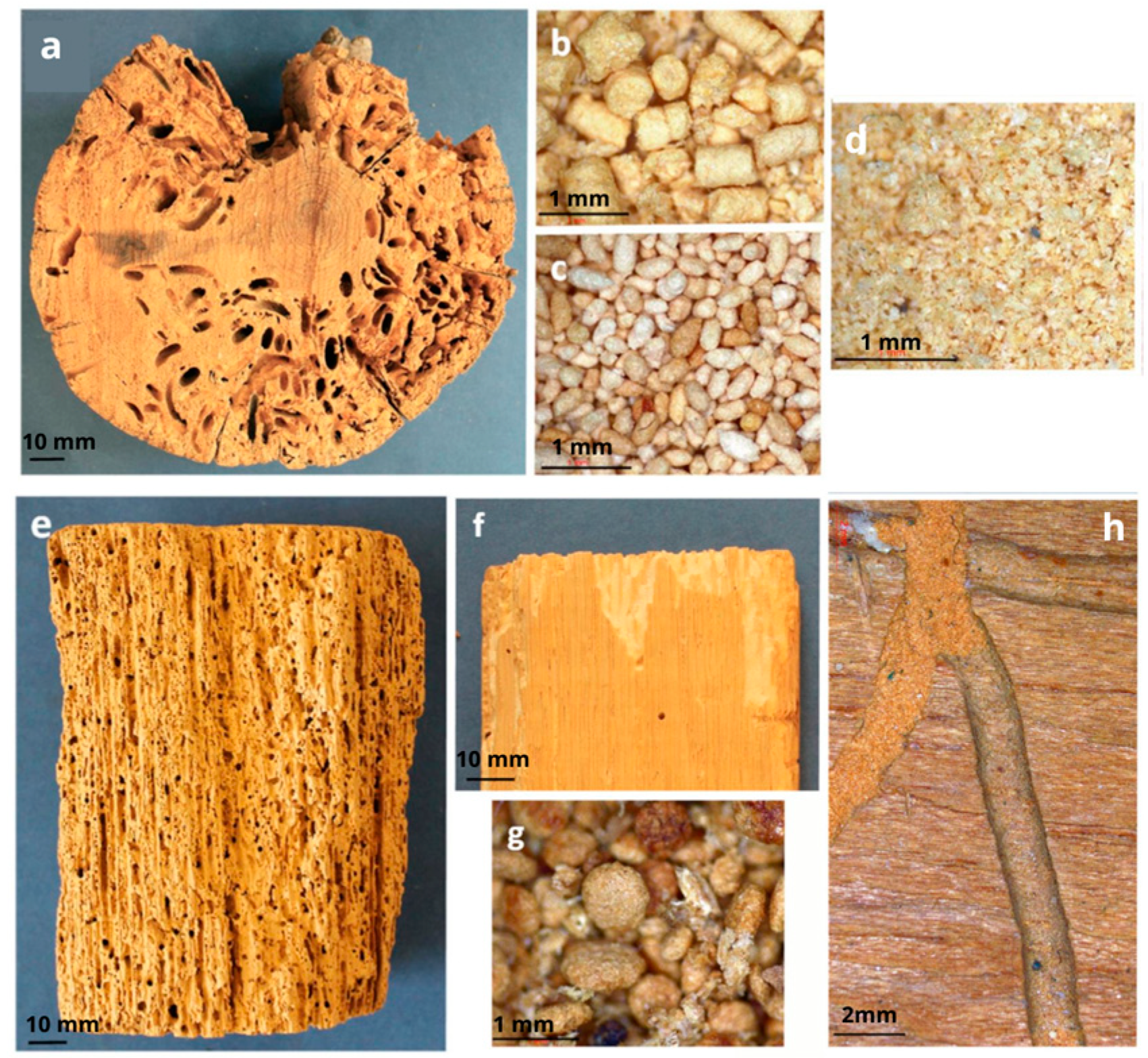
Figure 3. Galleries, exit holes, and dust excrements of widespread wood-deteriorating beetles in Europe: (a) oval galleries bored by Hylotrupes bajulus (Cerambycidae) in a cross section of a utility pole; (b) cylindrical dust excrements typical of Cerambycidae; (c) dust excrements of Anobium punctatum (Anobiidae); (d) amorphous dust excrements characteristic of Lyctinae (Bostrichidae); (e) wood heavily attacked by Anobiidae members; (f) skirting board attacked by Lyctinae (Bostrichidae) members; (g) dust excrements of Xestobium rufovillosum (Anobiidae); (h) a larval gallery partially filled with soft-to-the-touch dust excrements, bored by Lyctinae (Bostrichidae) members. (Readapted with permission from Ref. [21]. 2023, Martín J.A. and López R.).
Buildings 13 02929 g003
Figure 4. Insect mind map methodology. SI stands for Scenario Insect.
Buildings 13 02929 g004
Figure 7. Mind map methodology for glulam potential reuse assessment: S: scenario; C: cracks; I: insects; D: discolouration.
Buildings 13 02929 g007
Figure 8. (a) Glued laminated timber frame recovered by Articonnex; (b) dimensions and geometry of the structure; (c) lot numbering after removal.
Buildings 13 02929 g008
Figure 9. Glulam beam sectioning and sub-section specimen choice.
Buildings 13 02929 g009
Figure 11. Mind map approach application on glulam batch.
Buildings 13 02929 g011
Figure 12. Microscopic observations (×200 magnification) of a cross section: (a) depicting resin canal presence and gradual transition between earlywood and latewood; (b) showing resin canal presence.
Buildings 13 02929 g012
Figure 14. (a) Specimens before and after testing; (b) results of the adhesive line shear strength test.
Buildings 13 02929 g014
Figure 15. (a) Map summarising the distribution of the shear test results found (in MPa) along the beam. (b) Graphical display of pair-wise comparisons of SSs from Tukey’s HSD for the shear strength data.
Buildings 13 02929 g015
Figure 16. (a) Bending strengths of single laminates; (b) bending moduli of single laminates.
Buildings 13 02929 g016
Figure 17. Tested specimens: (a) wood failure type of single laminates; (b) knot presence in a tested 1.3.3 specimen of SS 1.3; (c) knot presence in a tested double laminate.
Buildings 13 02929 g017
Figure 18. Graphical displays of pair-wise comparisons of SSs from Tukey’s HSD: (a) bending strengths and (b) modulus data of single laminates.
Buildings 13 02929 g018
Figure 20. (a) Bending strengths of double laminates; (b) bending moduli of double laminates.
Buildings 13 02929 g020
Figure 21. Map summarising the distributions of the bending properties of double laminates (in MPa for the strength and GPa for the modulus) along the beam.
Buildings 13 02929 g021
Table 1. Fungus types and their distinct characteristics [21].
Fungus TypeGeneral Aspect and Mycelium with Hypha CharacteristicsFruit Body Characteristics
Serpula lacrymans (brown cubical rot)In high humidity: white, fluffy, cottony clusters; in dry condition: grey-white colour with vibrant yellow or lilac patches.Soft, fleshy layers with white edges.
Fibroporia vaillantii (brown cubical rot)White and soft.Shaped like a plate, dotted with tiny pores, and white in colour.
Coniophora puteana (brown cubical rot)The wood becomes highly fragile and can be crumbled by hand; virtually indistinguishable from Serpula attack.Infrequently observed slim plates of an olive-green hue.
Paxillus panuoides (brown cubical rot)Mycelium has a fibrous texture, appearing yellow or purple.Bell-shaped and muted yellow with pronounced gills underneath.
Amyloporia xantha (brown cubical rot)-Slim plate featuring tiny pores; of a yellow hue and with a lemony scent when fresh.
Lentinus lepideus (brown cubical rot)-Woody, brown fungus.
Phellinus contiguous (white rot)Wood fractures into fibrous strings; fungus mycelium is soft, fluffy, and light brown.Dark brown.
Donkioporia expansa (white rot)Hyphae are fibrous and of a white hue.Thick, leathery layers or shelves with a buff hue, featuring darker-brown pores.
Disclaimer/Publisher’s Note: The statements, opinions and data contained in all publications are solely those of the individual author(s) and contributor(s) and not of MDPI and/or the editor(s). MDPI and/or the editor(s) disclaim responsibility for any injury to people or property resulting from any ideas, methods, instructions or products referred to in the content.