Article

The Application Research of BIM Technology in the Construction Process of Yancheng Nanyang Airport

1
Faculty of Architecture, Civil and Transportation Engineering, Beijing University of Technology, Beijing 100024, China
2
China Construction Eighth Engineering Division Co., Ltd., Shanghai 200135, China
3
College of Civil Engineering, Tongji University, Shanghai 200092, China
*
Author to whom correspondence should be addressed.
Buildings 2023, 13(11), 2846; https://doi.org/10.3390/buildings13112846
Submission received: 18 October 2023 / Revised: 8 November 2023 / Accepted: 10 November 2023 / Published: 14 November 2023
(This article belongs to the Section Building Structures)

Abstract

:
The application of BIM technology in building construction provides the possibility to realize design accuracy, to visualize the construction details, to optimize construction schemes, and to enhance cooperation among various professionals. The Yancheng Nanyang Airport terminal 2 project, with its large span of steel roof structure, complex installation in mechanical and electrical pipeline (MEP) engineering, and difficulty in construction organization, is taken as the engineering background. The whole process application of BIM technology in the construction process is introduced. In structural engineering construction, the application of BIM technology can provide guidance for plane layout of the construction site, and can also assist in deepening the designs of irregular steel components. In steel construction, the application of BIM technology gives a commendable visual demonstration of the construction process of the metal roof system and the single-layer reticulated shell. In MEP engineering, the application of BIM technology provides a great approach to establish a synthesis of pipeline drawings to further form pipeline section diagrams and operation drawings. By integrating the dimension of time, precision control, and deviation rectification, a recursive construction drawing can be built. With respect to synergistic management, the quality and safety management in the construction site can be implemented on the basis of BIM terminal equipment as well. This paper will give a great reference on the application of BIM technology in the airport terminal construction.

1. Introduction

The structural design of an airport terminal is complex, with high construction standards, and involves various construction professionals. The airport terminal professional system is complex and difficult to construct. There are numerous professional teams on the construction site, and the cross-influence between professional engineering and civil engineering is significant, which leads to difficulties in management and other hidden dangers on the construction site. In order to solve the construction difficulties, new technical solutions need to be applied to assist in construction management. Stanford University firstly put forward a 4D model applied in construction management in 1996. The CIFE 4D-CAD system [1,2] is able to help managers intuitively discover the remaining problems in the construction process. A further improved model with a corresponding system called PM4D [3,4] was developed in 2003. This system could quickly generate the building’s cost budget, construction progress, environmental reports, and building life cycle cost analysis. In 2005, the University of Salford [5] exploited an nD model to integrate plan, cost, schedule, risk, sustainability, maintenance, and energy-savings. Adjei-kumi [6] proposed the PROVISYS model, which emphasizes the visualization of the site; however, construction management was concurrently neglected. Another kind of 4D model was provided by Rad [7], which focused on the calculation of lighting and texture color changes over time in the building.
All the models mentioned above are restricted to the partial application in the construction stage, and there is no unified data format that can meet the management needs of modern mega-construction projects. In 2002, Autodesk presented the strategy to utilize information technology in the construction industry, and a series of solution software were successively exploited. BIM is a kind of building information modeling that integrates all sorts of information in the construction project based on 3D digital technology. Moreover, it is a method to directly apply digital technology to the construction process of design, construction, and management [8]. Tulke and Hanff [9] proposed a model based on BIM to calculate project schedules. Tory and Swindells [10] developed a visual TASM system to enhance the construction schedule presented by the traditional Gantt chart and Network chart. Akinci and Fischer [11] developed a 3D building design model to evaluate the collision problem encountered in construction by adding building information and temporary facilities. Sacks and Treckmann [12] developed an interface similar to a traffic signal, which was used to report the status and progress of construction. Hewage and Ruwanpura [13] deployed an information display method through displays and printers to achieve real-time communication with workers, significantly improving production efficiency by reducing the time cost of understanding design information. Zhang and Arditi [14] realized the automatic control in construction site by means of laser scanning technology, which is connected to the construction progress control system. Statistic data from the Erabuild foundation in 2008 [15] indicated that BIM technology is used in 20% of architectural design projects and 10% of construction projects in four Nordic countries, and representative projects thereof include the main stadium for the London Olympics, Eureka Tower in Melbourne, and Liberty Tower in New York. The American building SMART alliance [16] conducted a survey on the application of BIM in the engineering field in the United States, and summarized 25 different applications of BIM at present, involving four stages—planning, design, construction, and first-level operation—which include site analysis, phase planning, design proposal demonstration, sunlight analysis, site-usage planning, digital fabrication, 3D coordination, maintenance plan, asset management, disaster plan, etc. Song et al. [17] described a BIM-based structural framework optimization and simulation system for managing construction planning and scheduling. According to the optimized schedules, the authors also conduct a dynamic construction process visualization to determine the amount of work required for major construction processes by applying a predefined calculation formula and logic, along with 3D geometry data and process data. Chen L. and Luo H. [18] explored the advantages of 4D BIM in management applications based on building standards and specifications. Ma Z. et al. [19] proposed an approach to make the process of construction quality management more effective and collaborative, which is to develop a system based on the integrated application of building information modeling (BIM) and indoor positioning technology. In order to fully understand the actual progress of the construction project, a novel framework for automated process discovery from building information modeling (BIM) event logs was developed by Pan Y. and Zhang L. [20]. To assess the BIM capabilities in individual building life cycle stages and their processes, Yilmaz G. et al. [21] developed a BIM capability assessment reference model (BIM-CAREM) and demonstrated its usability through multiple explanatory case studies, which was performed with two international design and engineering companies and two general contractors in Turkey. As a new technology, BIM is making revolutionary changes to traditional management modes.
Yancheng Nanyang Airport terminal 2 is a national first-class airport with open air ports, and occupies an area of 50,000 m2. It involves many professional projects such as steel structure engineering, metal roofing engineering, curtain wall engineering, mechanical, and electrical pipeline engineering. The total weight of the steel structure engineering is 4000 t and the span exceeds 200 m. The metal roofing is a hyperbolic shape with an area of over 26,000 square meters, and there are nine diamond-shaped aluminum alloy sunroofs in the middle of the roof. The mechanical and electrical pipeline engineering contains more than 20 professional division projects, with pipeline installation projects exceeding 20 km in length. However, the entire construction period is only 600 days, the number of construction workers will exceed 1000, and the flow of vehicles in and out will exceed 500 vehicles per day during the peak construction period. Moreover, the engineering quality standards are very high, which induces to difficulties in construction organizations and high construction risks. In this paper, the application of BIM technology in the construction process of Yancheng Nanyang Airport is introduced in detail. Through the application of BIM technology, the BIM model of Yancheng Nanyang Airport terminal 2 is established in advance and updated in time, which provides convenience for site management. The construction process of steel structure engineering is simulated before construction in the BIM model, and the construction difficulties are controlled in advance. For mechanical and electrical pipeline engineering, a comprehensive BIM diagram was established through BIM deepening design and pipeline optimization layout, and a recursive pipeline construction method was invented to solve the pipeline installation problem.

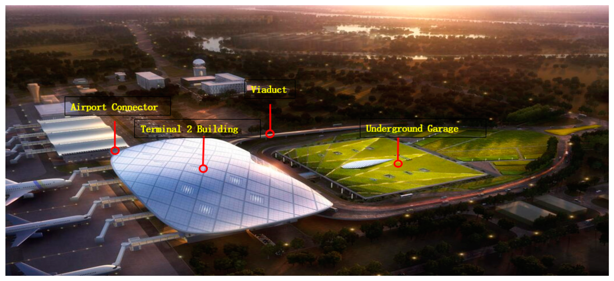
2. General Situation of Yancheng Nanyang Airport

The total construction area of Yancheng Nanyang Airport terminal 2 is 50,000 square meters, including terminal 2’s main building, underground garage, viaduct, and airport connection, as shown in Figure 1. The main building is a mega structure, with a height of 27 m, a length of 216 m from east to west, and a length of 108 m from north to south. There are two floors above ground, with a construction area of 28,000 square meters, and one underground floor with a construction area of 2200 square meters. The viaduct in front of the terminal building has a total of nine spans, with a 442 m long and 25 m wide bridge floor. The airport connector has two floors above ground, with a height of 11.45 m and floorage of 1972 square meters.
The main structure of terminal 2 consists of a roof steel structure, an exposed single-layer reticulated shell, and a metal roof panel system. The steel grade is Q390. The total weight of steel roof structure is 1832 t, which is composed of a longitudinal truss, transverse truss, skylight, and edge beams, as shown in Figure 2a. The exposed single-layer reticulated shell is located in the northwest side of roof, which has a total tonnage of 1000 t. The exposed single-layer lattice shell has a large span, large waves, large overhang, and three-dimensional spatial shape, as shown in Figure 2b. The metal panel system is an elliptical hyperbolic shape with a total area of 26,450 square meters. The structural waterproofing level is grade 1, using a double-layer waterproof structure and open decorative aluminum veneer. The upper layer uses the standing seam roof system, and the lower layer is made up of 1.5 mm PVC waterproof roll and nine rhombic aluminum skylights located in the middle of roof, as shown in Figure 2c.

3. Application of BIM Technology

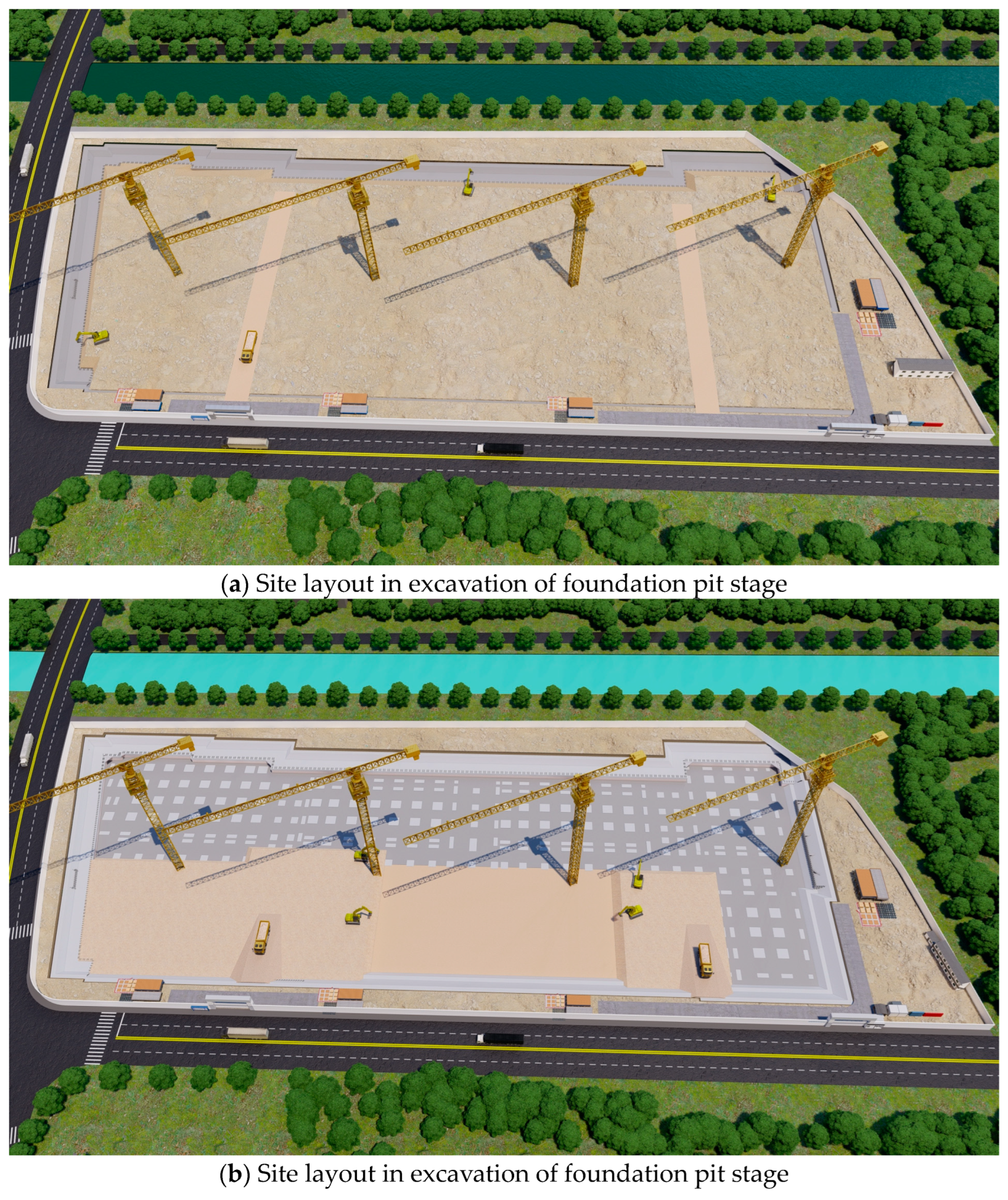
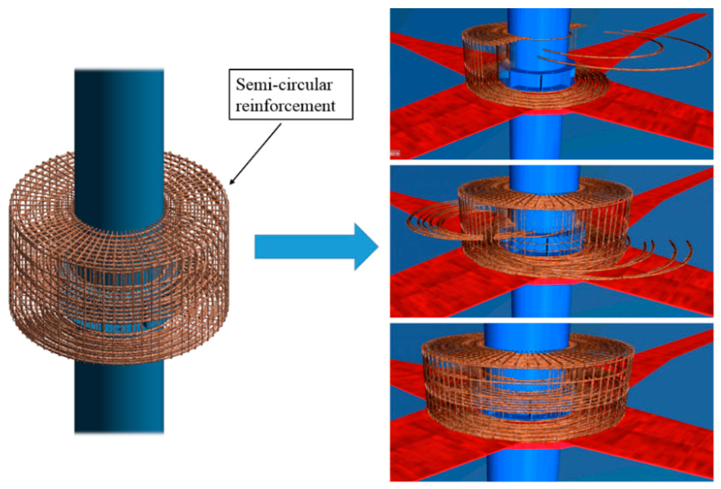
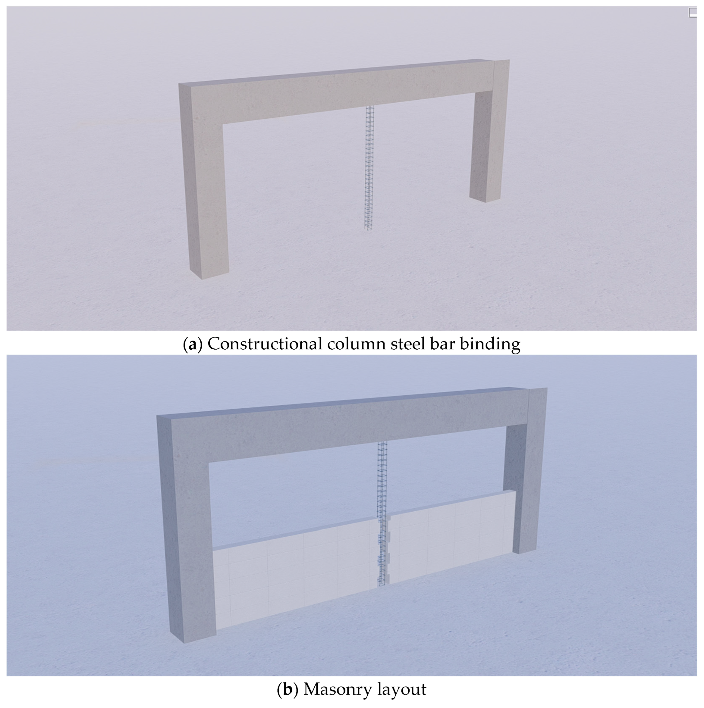
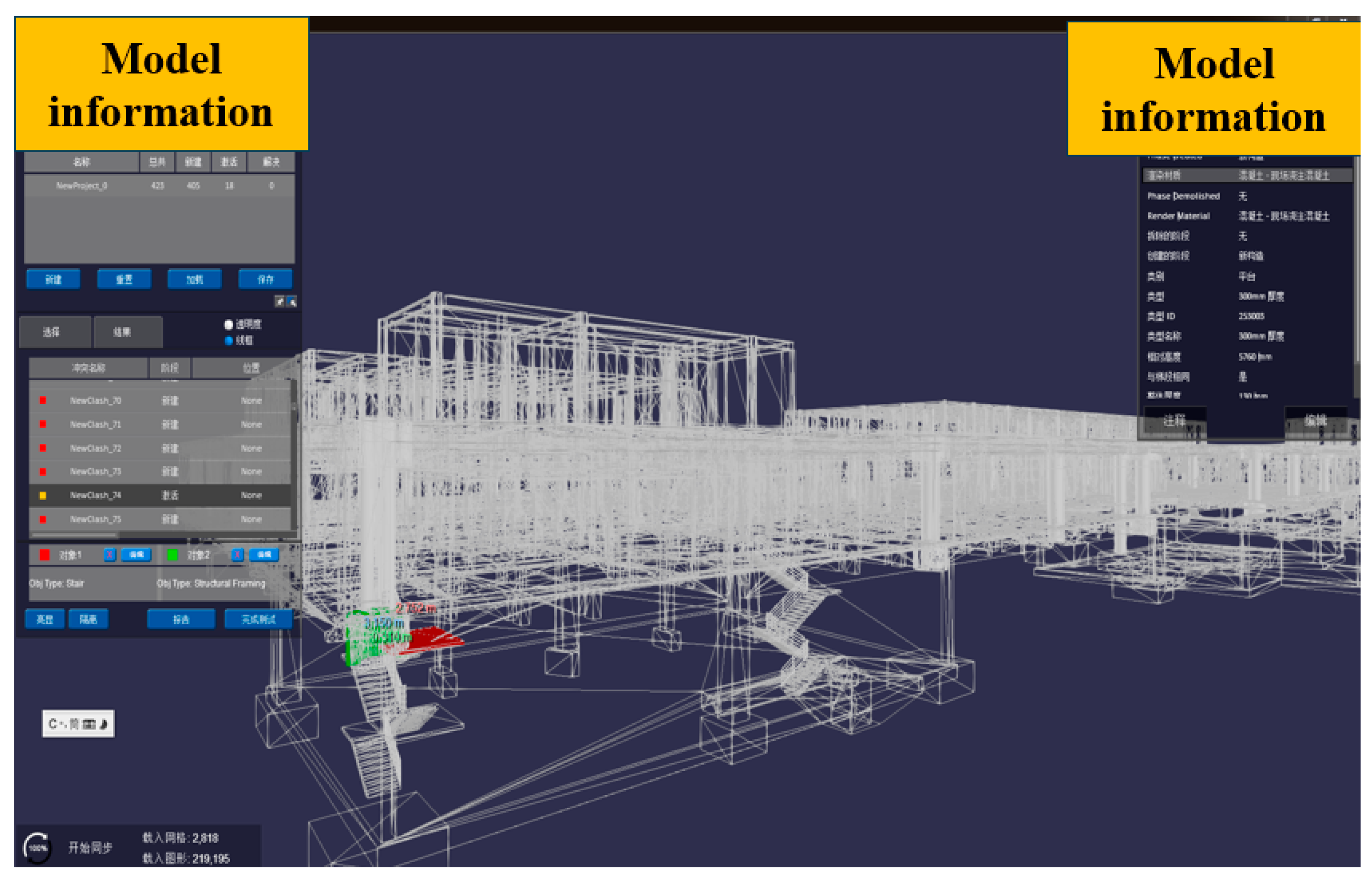
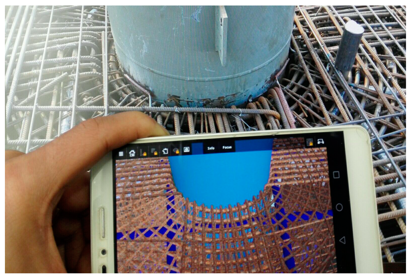
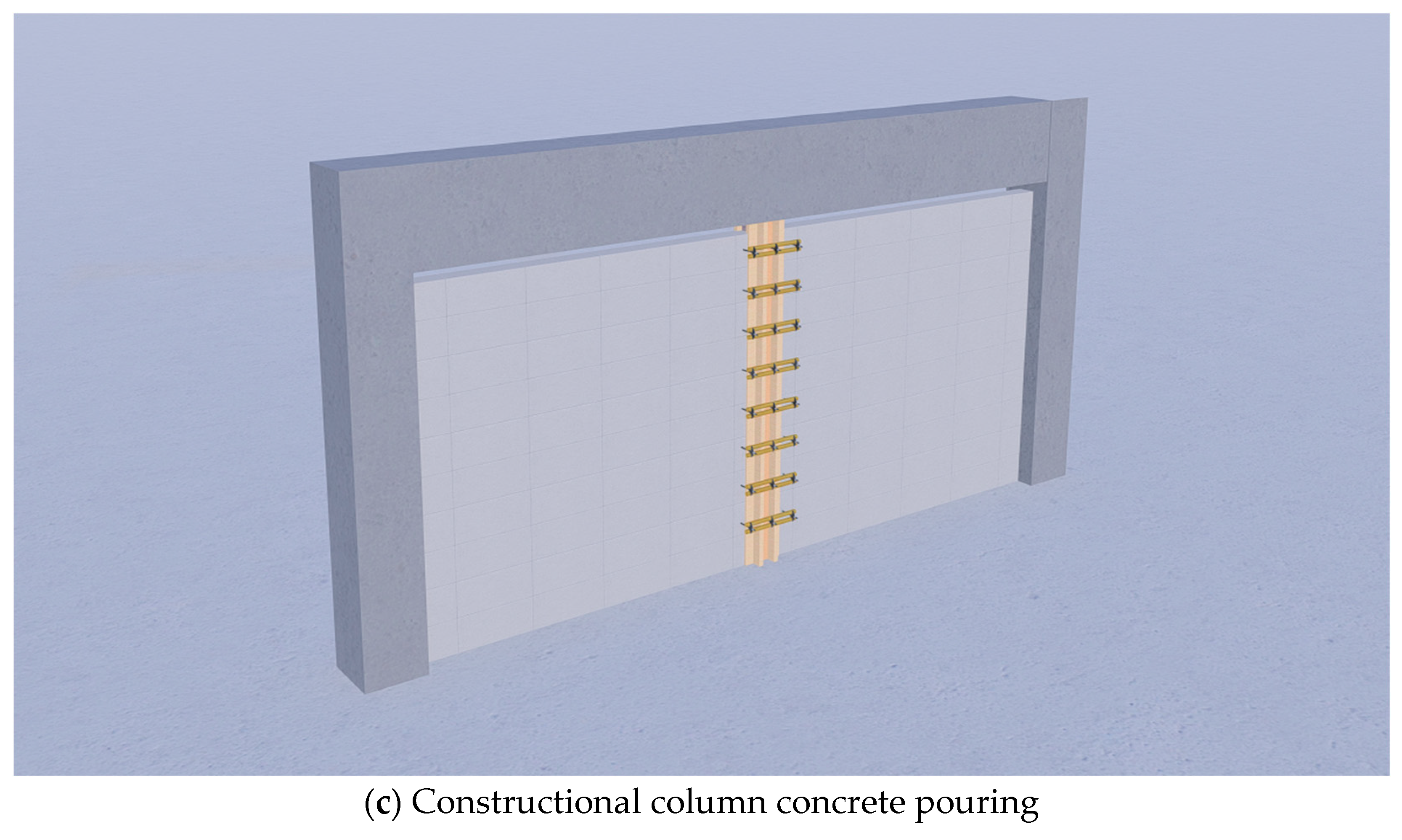
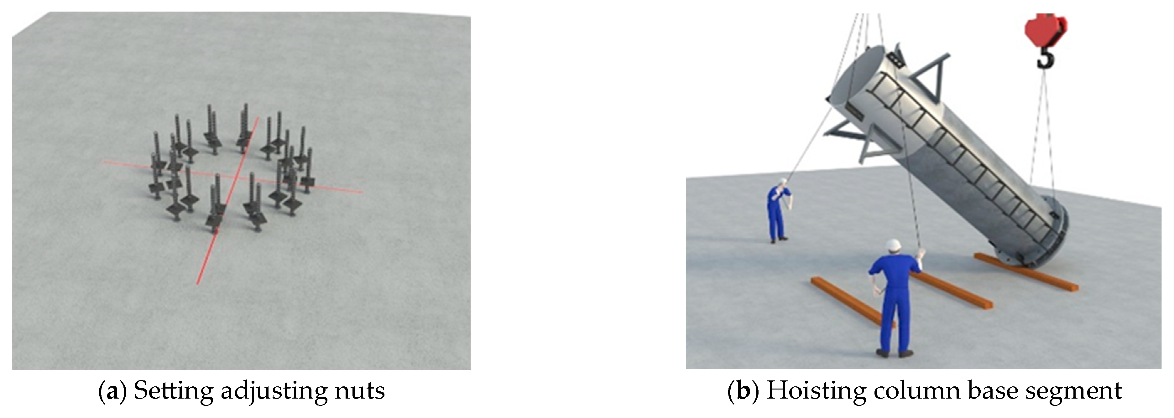
3.1. Application of BIM in Civil Engineering

The longitudinal span of the terminal 2 building is 108 m and the lateral span is 216 m, which induces a longer component length and a large area of construction operation. This not only results in inconvenience in transportation and component installation, but also difficulty in the construction organization. BIM serves as an important role in solving these problems.
(a) Site management: The BIM model is established in advance and updated in time to provide tools for the site, realizing a dynamic management. The information about traffic moving lines concerning incoming member transportation vehicle and construction material as well as the position of a truck crane and a concrete pump truck will be simulated in a prior day. The dynamic report is then to be generated. The specific vehicle entry and exit timeline, vehicle sequence, and vehicle positions provided in the report will ensure an organized arrangement in site, as shown in Figure 3.
By presenting different site changes in the construction cycle, the working conditions are shown in detail to facilitate the organization of construction site management.
(b) Drawing review: The drawings will be deliberately checked as the BIM model is being established. The errors in the drawings will be gathered to form a problem report. The subsequent step is organizing the project visual communication to demonstrate the problem rationality and deciding whether it is worth presenting the problem to the design institute. The LOD (level of detail) precision of the model in the construction stage is no less than 400 in order to guarantee the model’s capability to precisely reproduce the construction site. In the BIM modeling process, an inconsistency between architectural drawings and the structural detail drawings of the garage roof and drainage ditch was found. This issue is then submitted to generate a problem report, conducting the garage drawing revision to guide the actual construction operation as well as reducing the rework, as shown in Figure 4. In addition, in the simulation of steel column base hoisting, a reinforcement collision problem is captured by BIM modeling. Moreover, it is revised and optimized to avoid reworks due to collision problems, as shown in Figure 5.
(c) Optimization of construction difficulties: A 3D visualization function of BIM makes it competent to reproduce construction difficulties and complicated joint details. With the utilization of BIM, an optimized scheme can be proposed to sufficiently reduce the time cost as well as to improve the construction efficiency. Taking the prestressed reinforcement ring beam joint in this project as an example, the 3D model gives the solution of making the reinforcement jointed and tied in a semi-circular form to reduce preparation work of reinforcement, as shown in Figure 6.
(d) Simulation of construction scheme: Traditional 2D model makes it hard to reproduce dynamic construction process. The emergence of BIM overturned this awkward situation, providing it is equipped with dynamic management characteristics. For this project, a 3D analysis of the construction scheme was completed, capacitating the managers organized to discuss the construction procedure with the BIM model. An inerrant construction operation is ensured by the simulated interpretation of the design intention in the construction procedure, which is provided by the simulation of the BIM animation. Taking the masonry layout scheme in the airport terminal as an example, a rational layout scheme is proposed in the framework of BIM in advance. The masonry construction technology simulation is conducted to make the construction standard and technical disclosure standard clarified, as shown in Figure 7.

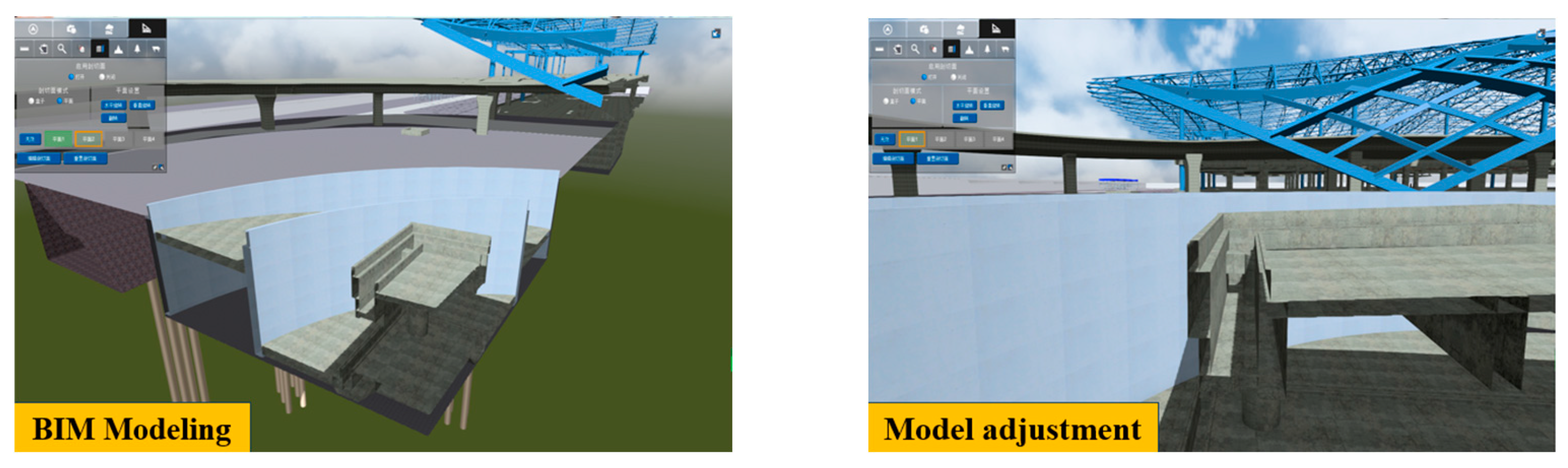
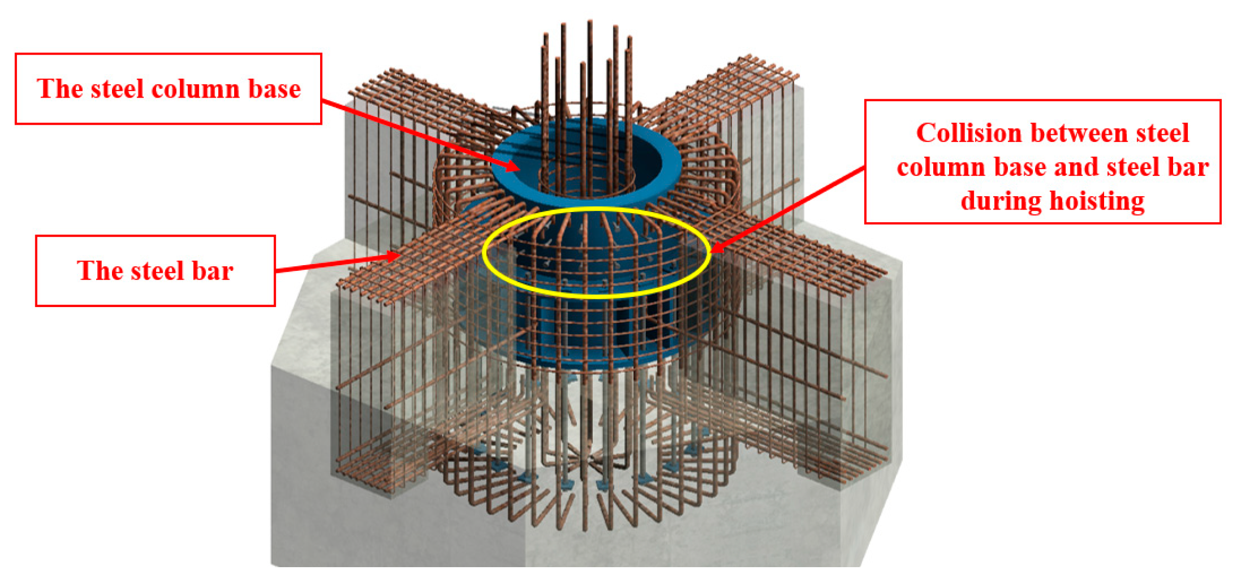
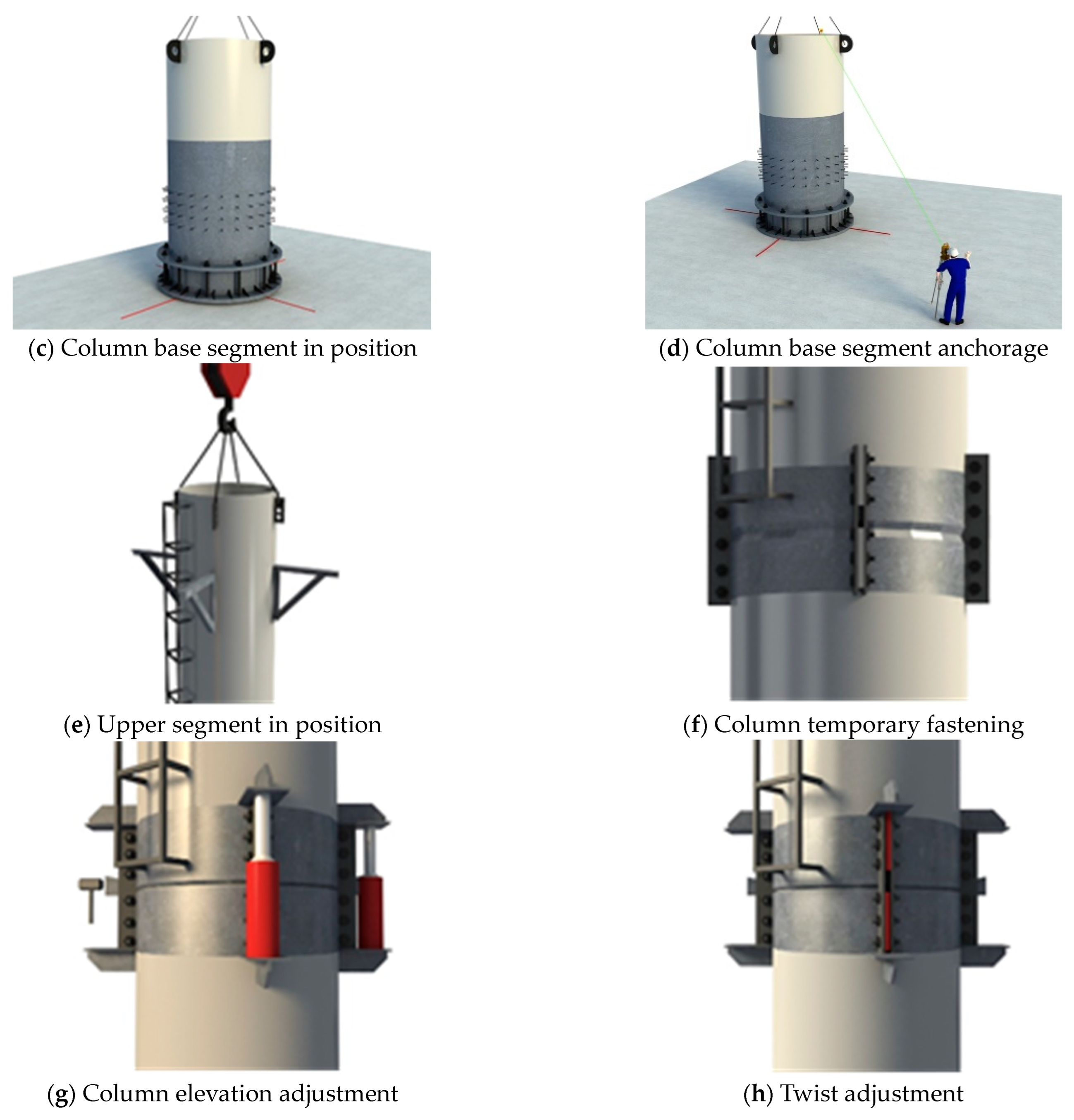
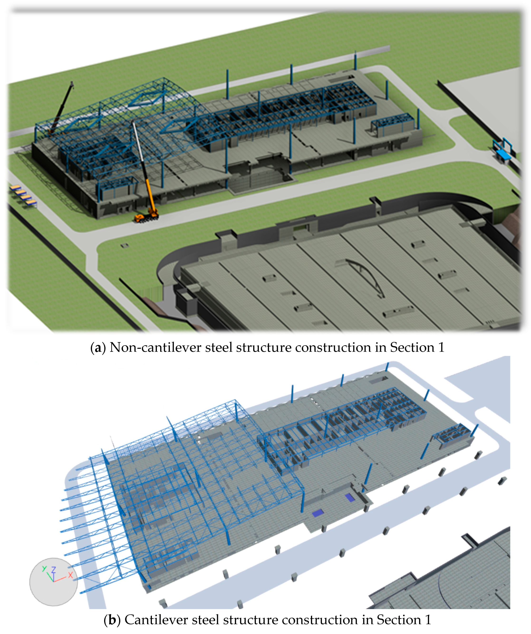
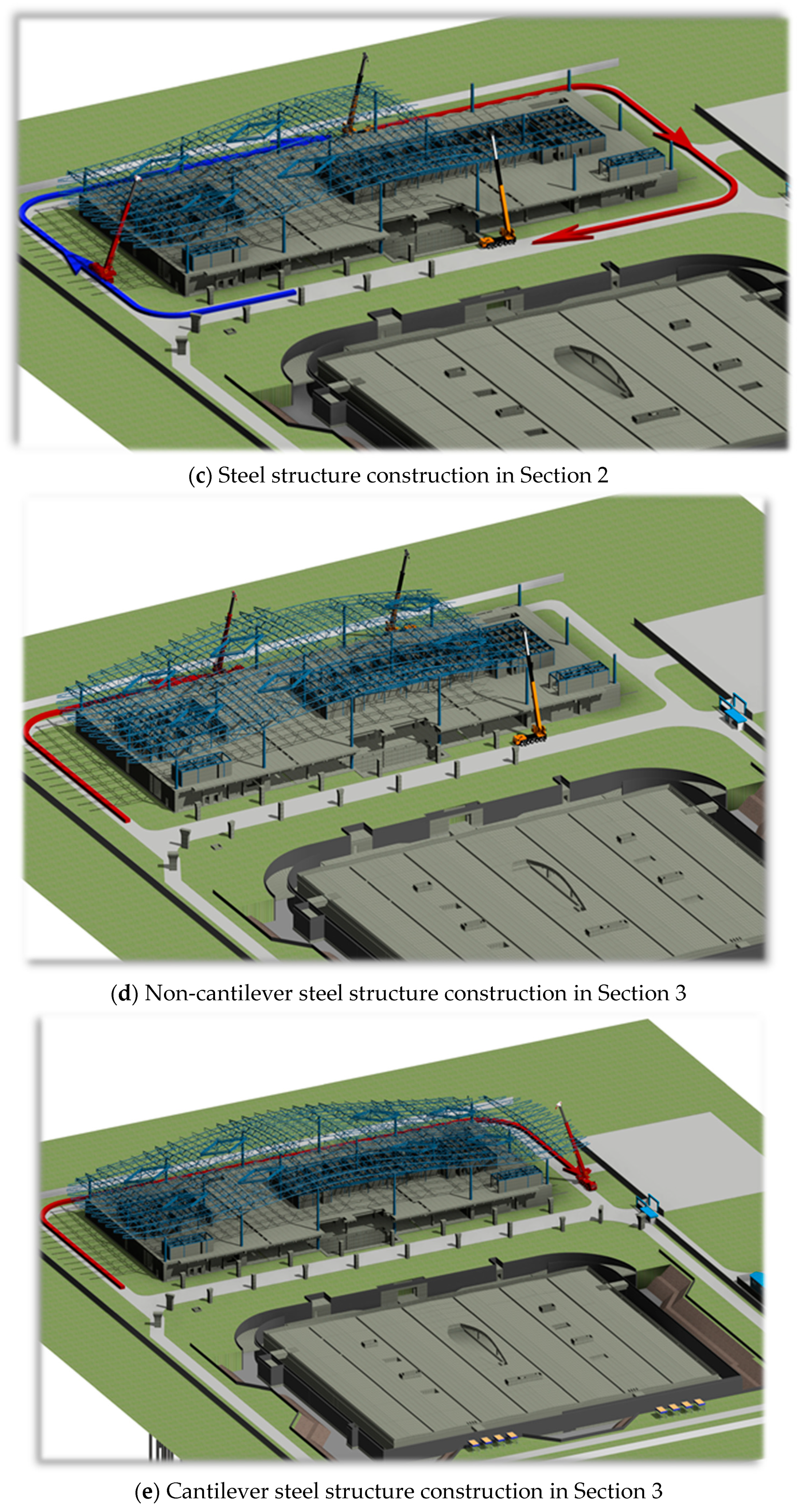
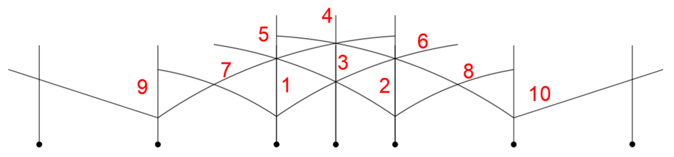
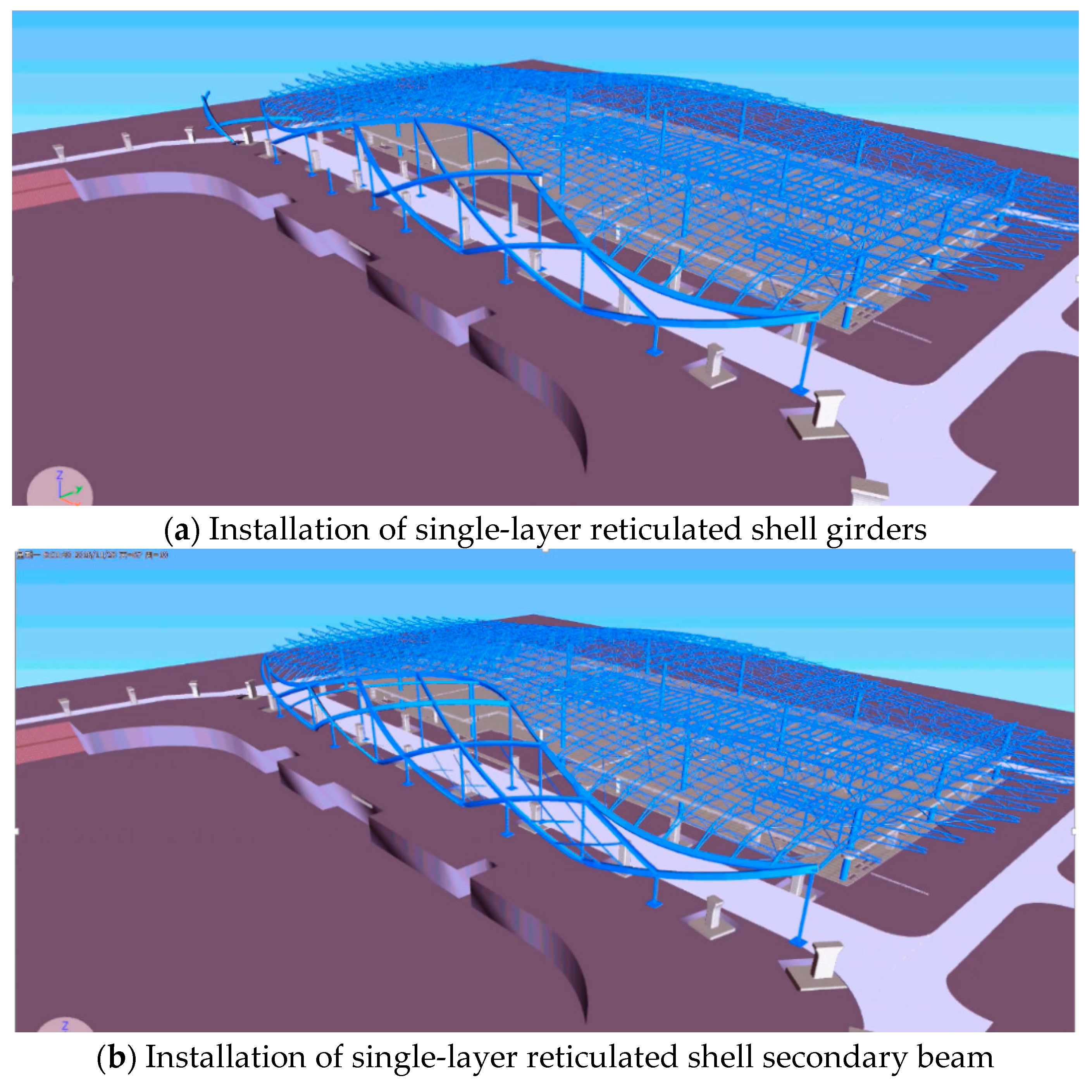
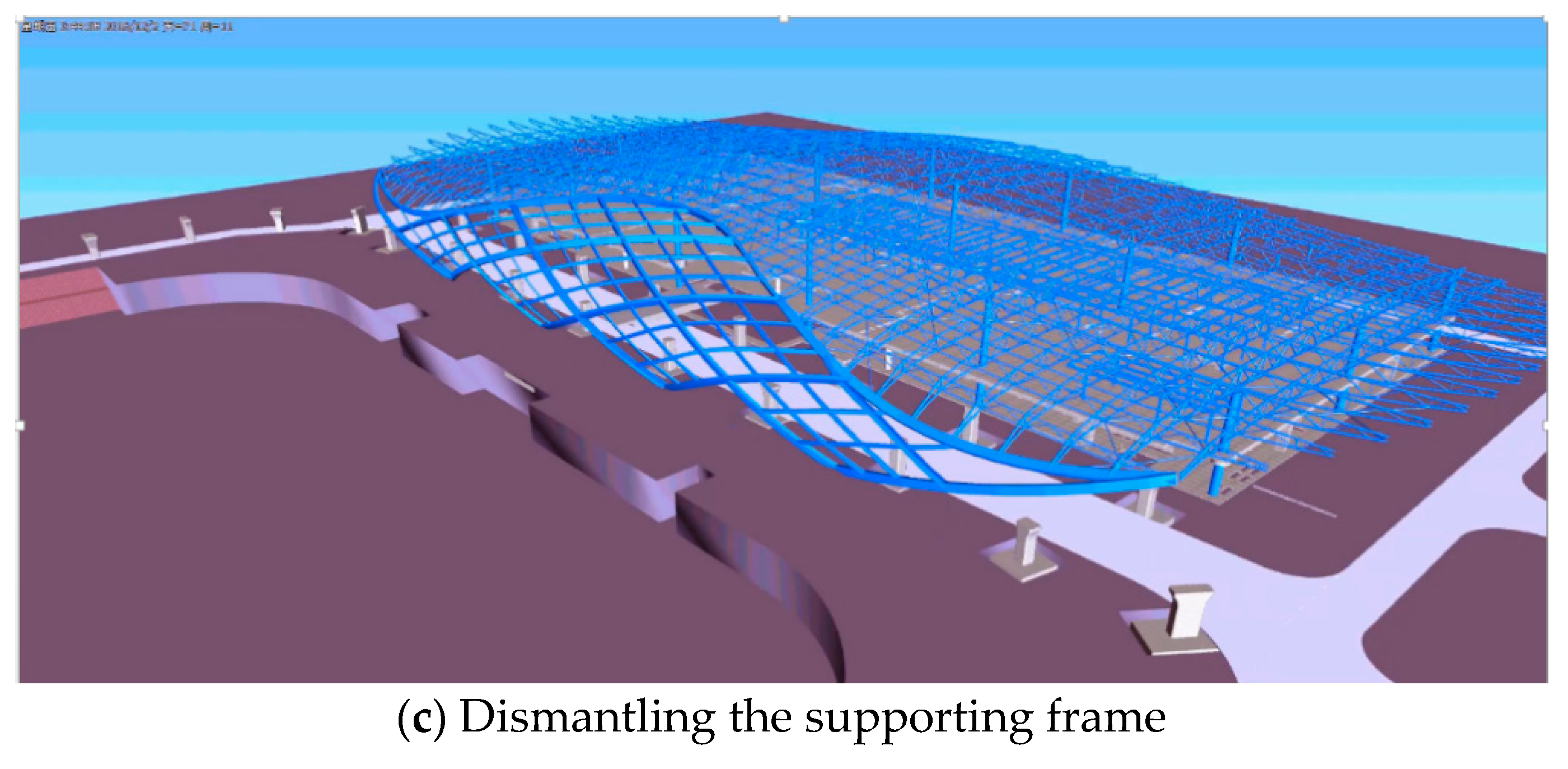
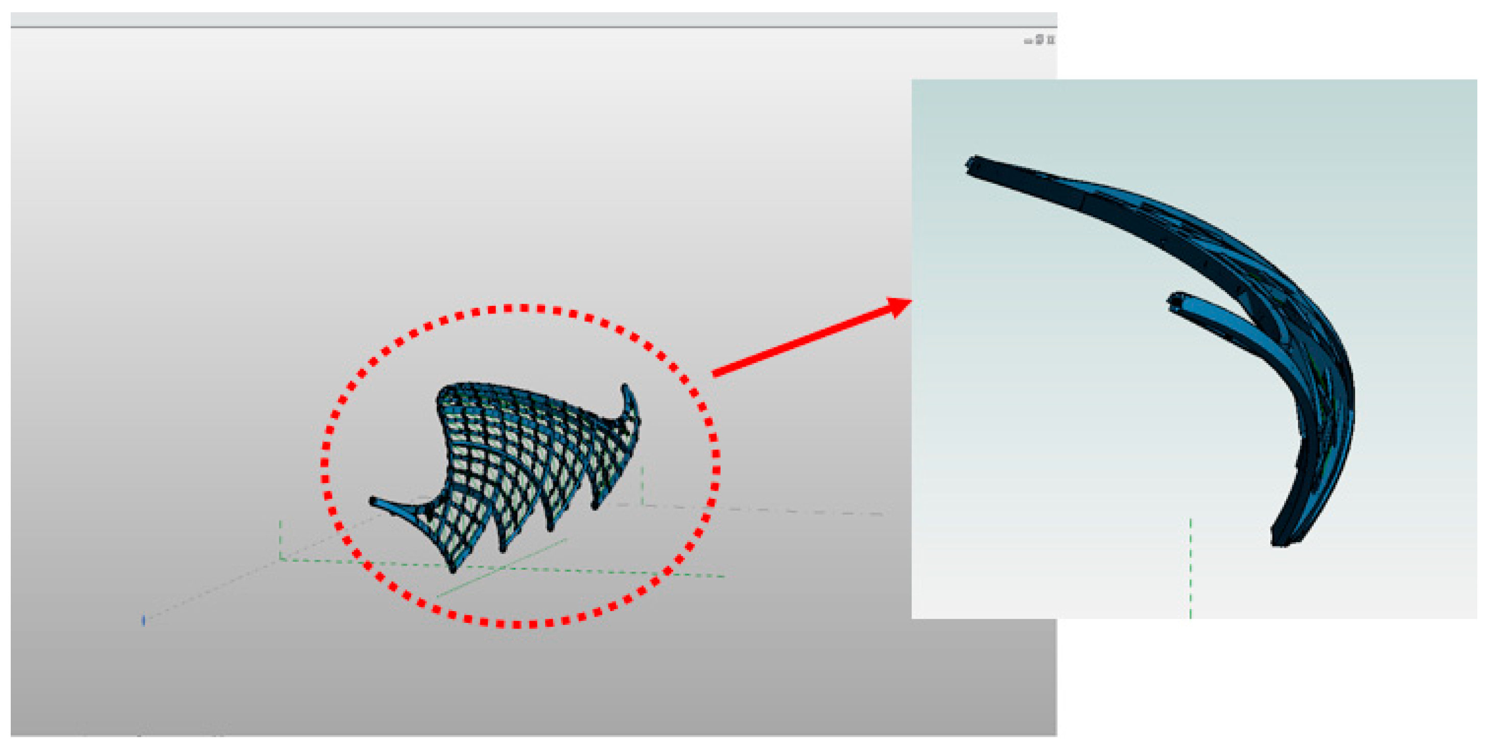
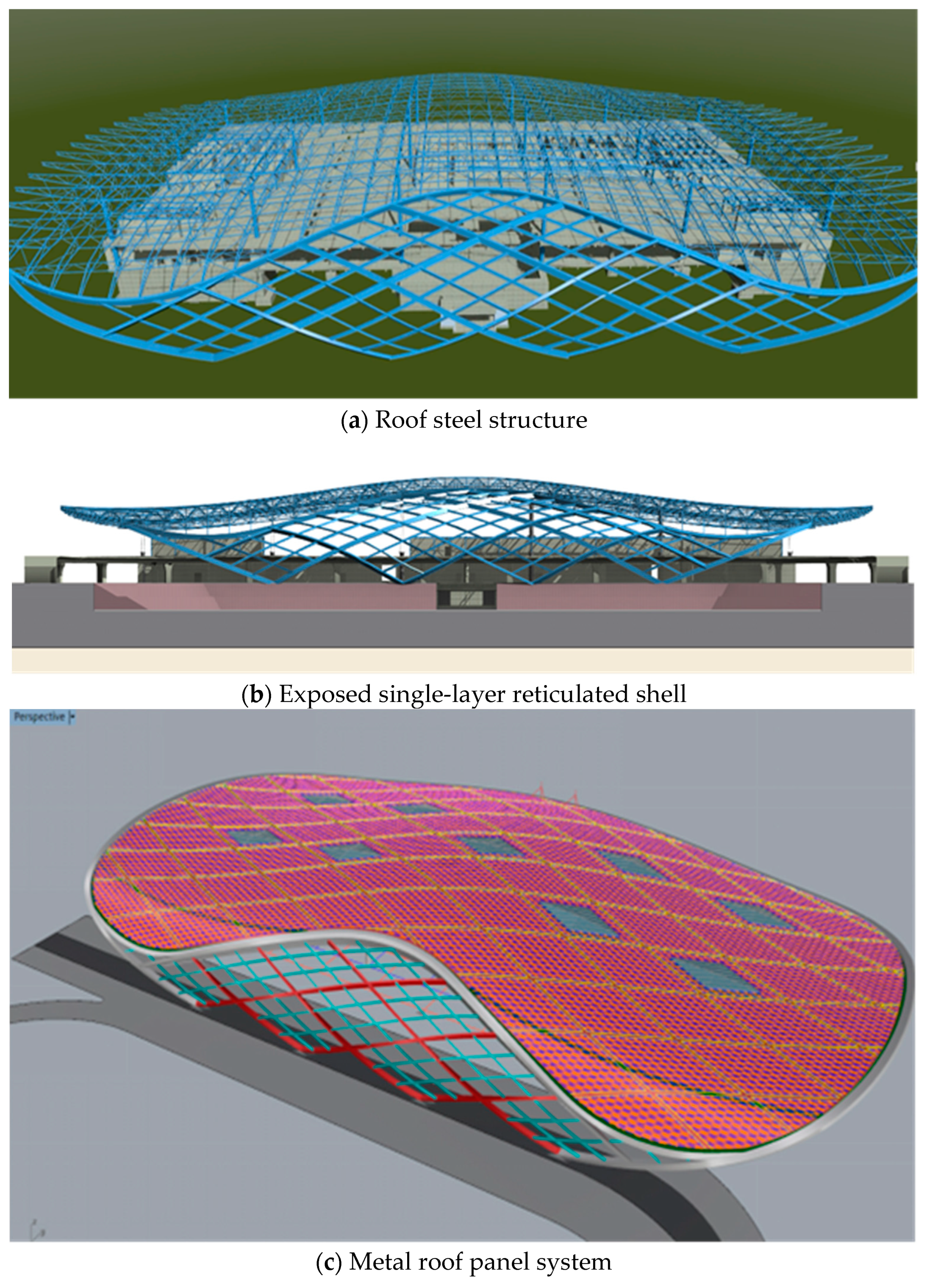
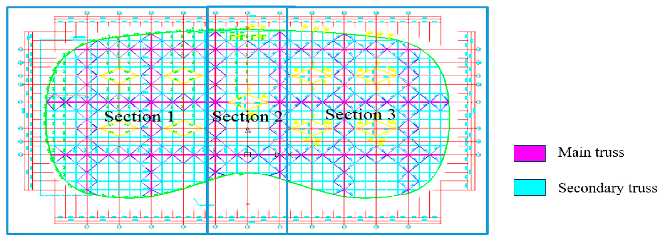
3.2. Application in Steel Structure

The roof steel structure is made up of a “w”-shaped double-layer reticulated shell and a hyperboloid single-layer lattice shell. The complicated structure model coming from varied curvy shapes, diversified structural components, and a cantilever span of over 40 m results in an increase in security control difficulty in the construction process.
The roof of the airport terminal is supported by 18 concrete-filled steel tubular columns with the total tonnage of 367.32 t. Its column space is 36 m × 36 m. The column is special-shaped with rhombic sections in the bottom and circular sections on the top. Among them, the longest is 15 m and the heaviest is 13.9 t. The heavy weight of these steel tubular members adds difficulties not only in the hoisting, but in the adjustment process of verticality and elevation. This challenge is able to be solved by three-segment decomposed hoisting on the premise of column location settled by embedded anchor bolts. The first segment of the column is hoisted by a nearby 100 t crawler crane. The second segment is hoisted by a 250 t crawler crane. The third segment is hoisted last. Finally, the adjustment of elevation and twist shall be implemented. BIM plays an important role in guaranteeing the precision control of conducting construction process simulations, as shown in Figure 8.
(b) Piece-wise and stepwise-based roof steel structure installation: The truss and skylight are hoisted piece-wise. Other parts are bulk-way assembled at high altitudes. Based on the roof truss structure and construction sequence, the whole roof structure is separated into Section 1, Section 2 and Section 3, as shown in Figure 9.
Because of the 40% area proportion of cantilever truss in the total steel roof structure and maximum one-sided cantilever length of nearly 40 m, the construction in each section proceeds according to the cantilever zone and non-cantilever zone, respectively. The whole roof installation sequence is longitudinal and transverse, with the main truss installed at first and then the sub-truss is installed in between. The truss at the top of the roof shall be installed by the crawler crane after the concrete in the special-shaped column is poured. Based on the execution conditions and road conditions in the construction site, the installment sequence begins with Section 1, then Section 2, and finally Section 3. BIM provides a whole process simulation for the roof steel structure construction to ensure the safety and efficiency, as shown in Figure 10.
(c) The exposed single-layer reticulated shell is kind of a grid box structure made up of welded rectangular box sections, with the overall width of 180 m and height of 22.1 m. The largest size of the box sectional beams is 1200 × 600 × 25 × 25. For the reticulated shell, four upholding supports at the bottom together with connections on the top make it an overall stable structure. In order to avoid the accumulated installment deviation, as well as to enhance the construction efficiency, the installation method follows the principle of setting support frames and in situ lifting components. The construction sequence is from middle to the sides and from bottom to top, divided into a total of 10 areas. Figure 11 gives the division of the hoisting area. The simulation of installation procedure is implemented in the BIM model, as shown in Figure 12.
(d) Model deepening: The BIM model can complete a detailed design of the connection joints as well as offering construction drawings, carrying on a precise fabrication and hoisting. BIM realizes the structural member deepening design and fabrication data extraction of the special-shaped members, which are unable to be completed by traditional 2D work pattern, as shown in Figure 13.

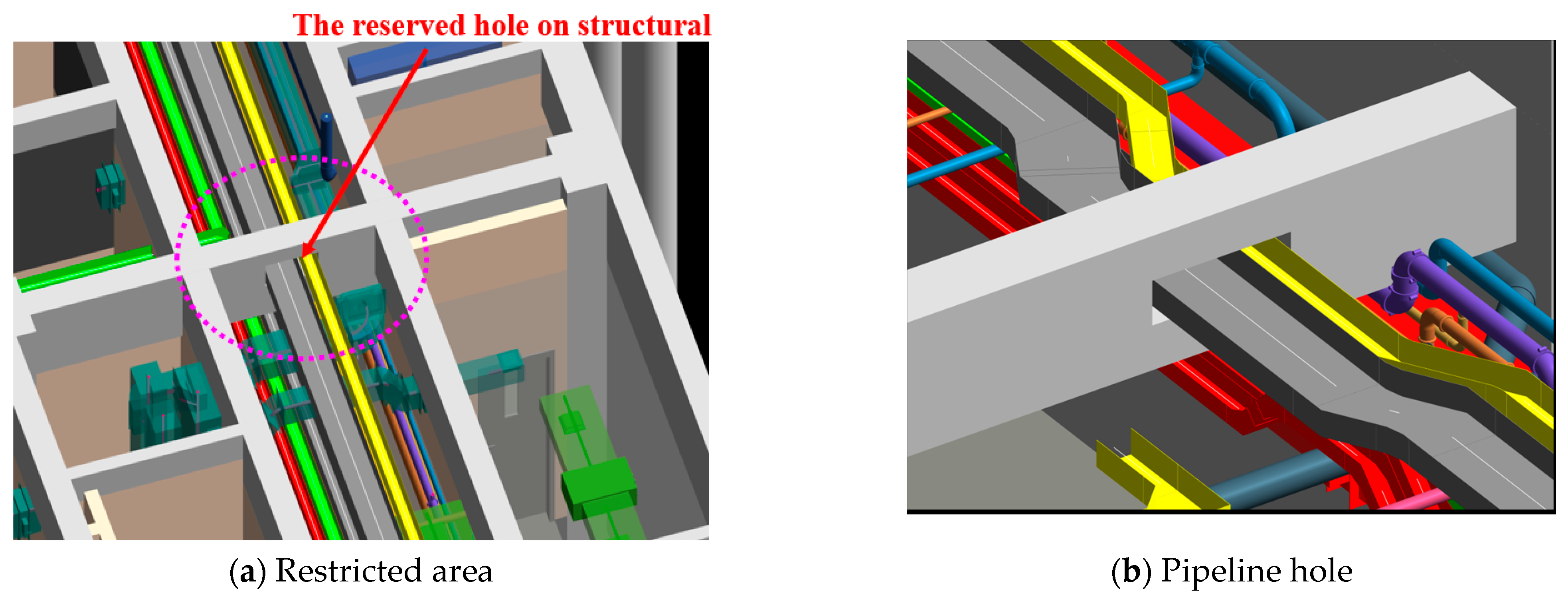
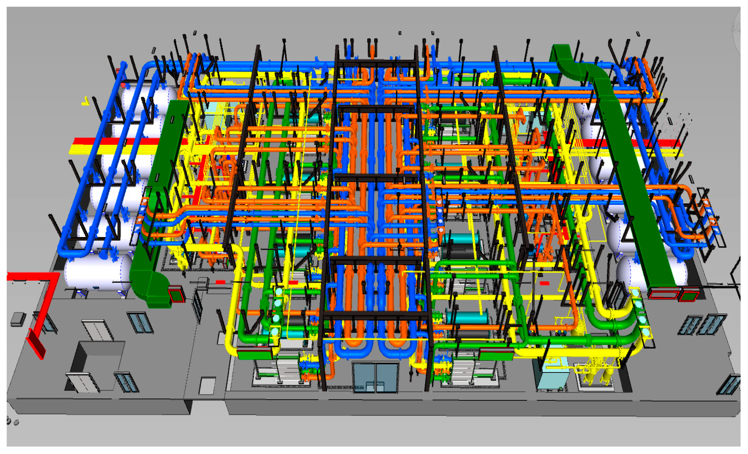
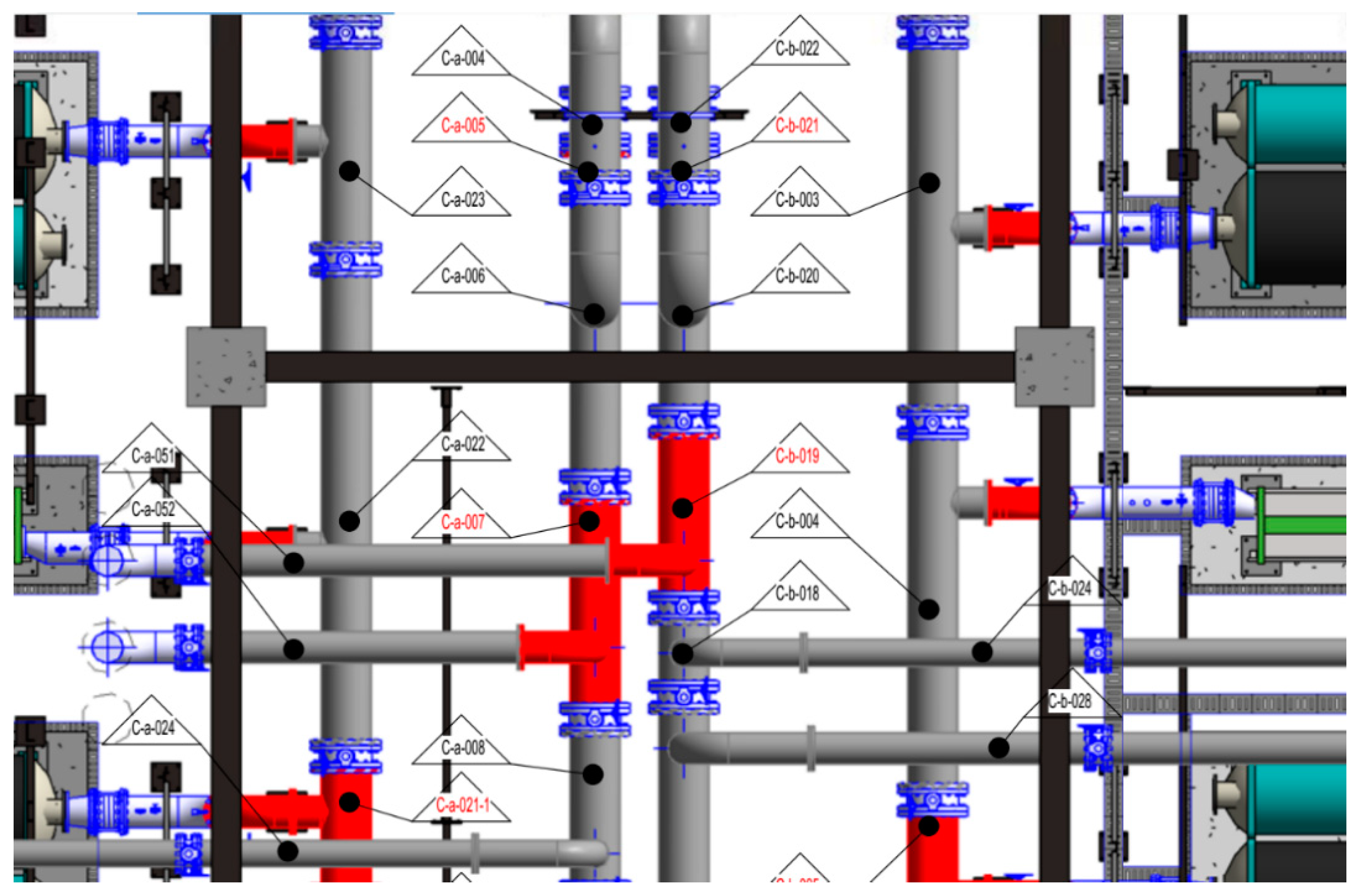
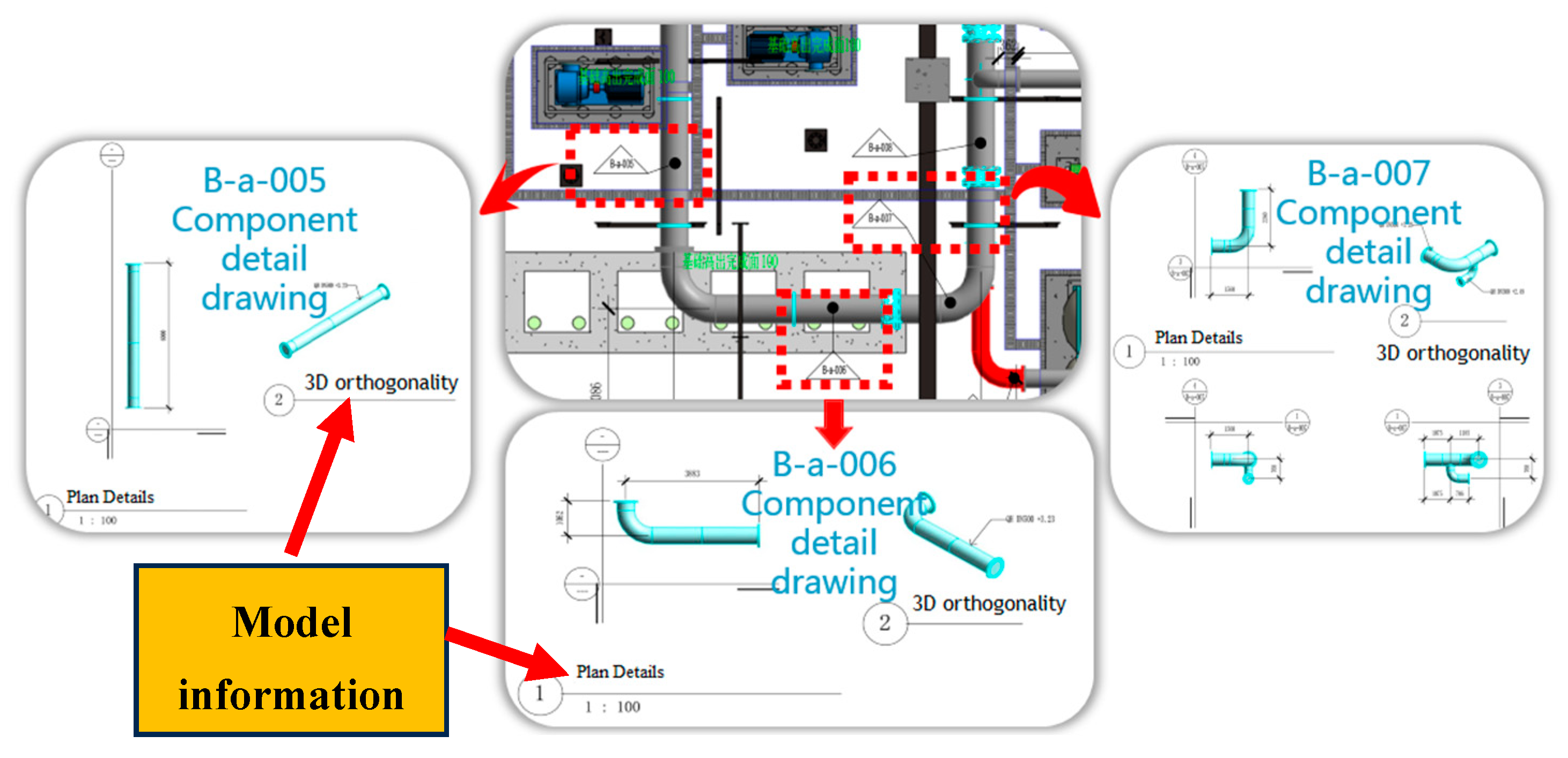
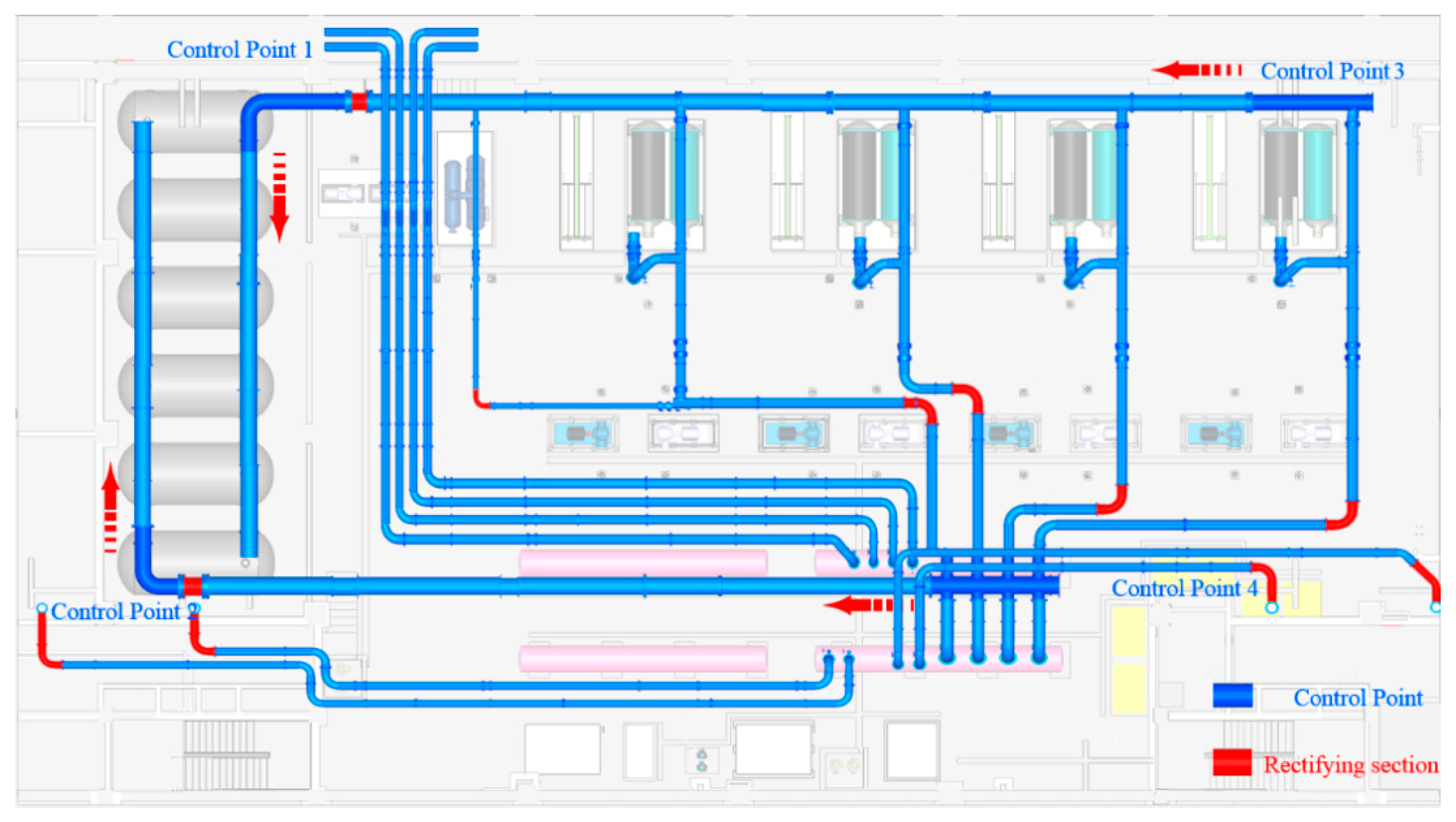
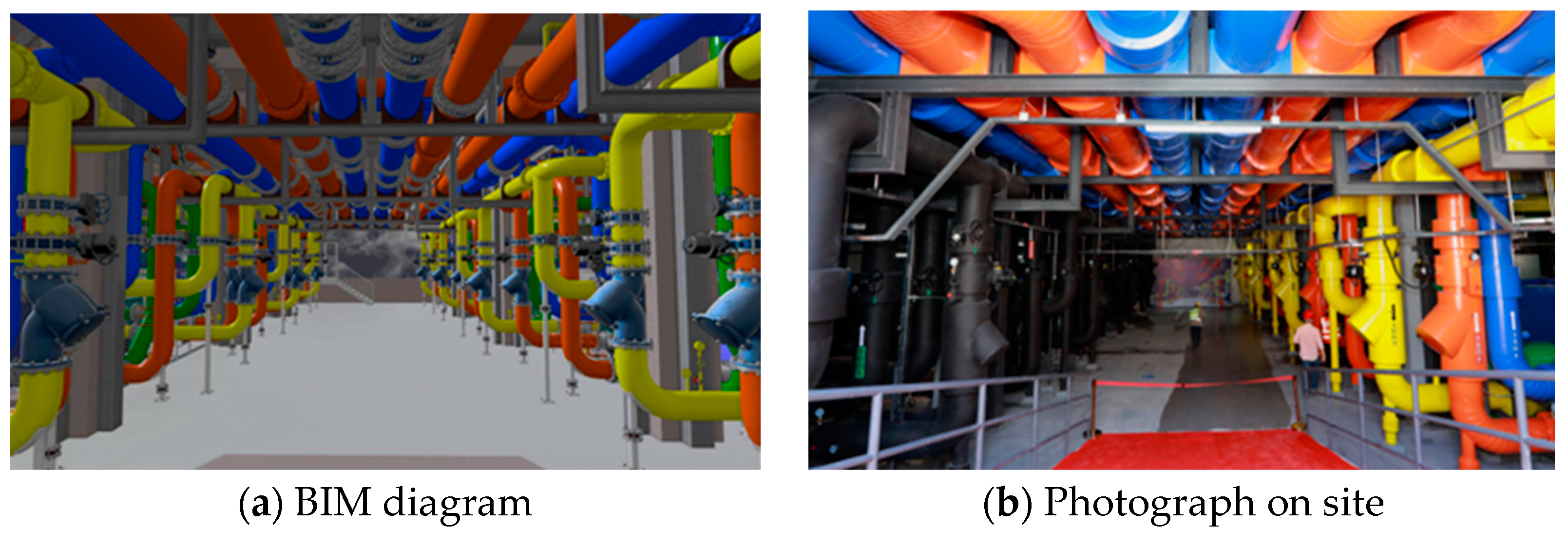
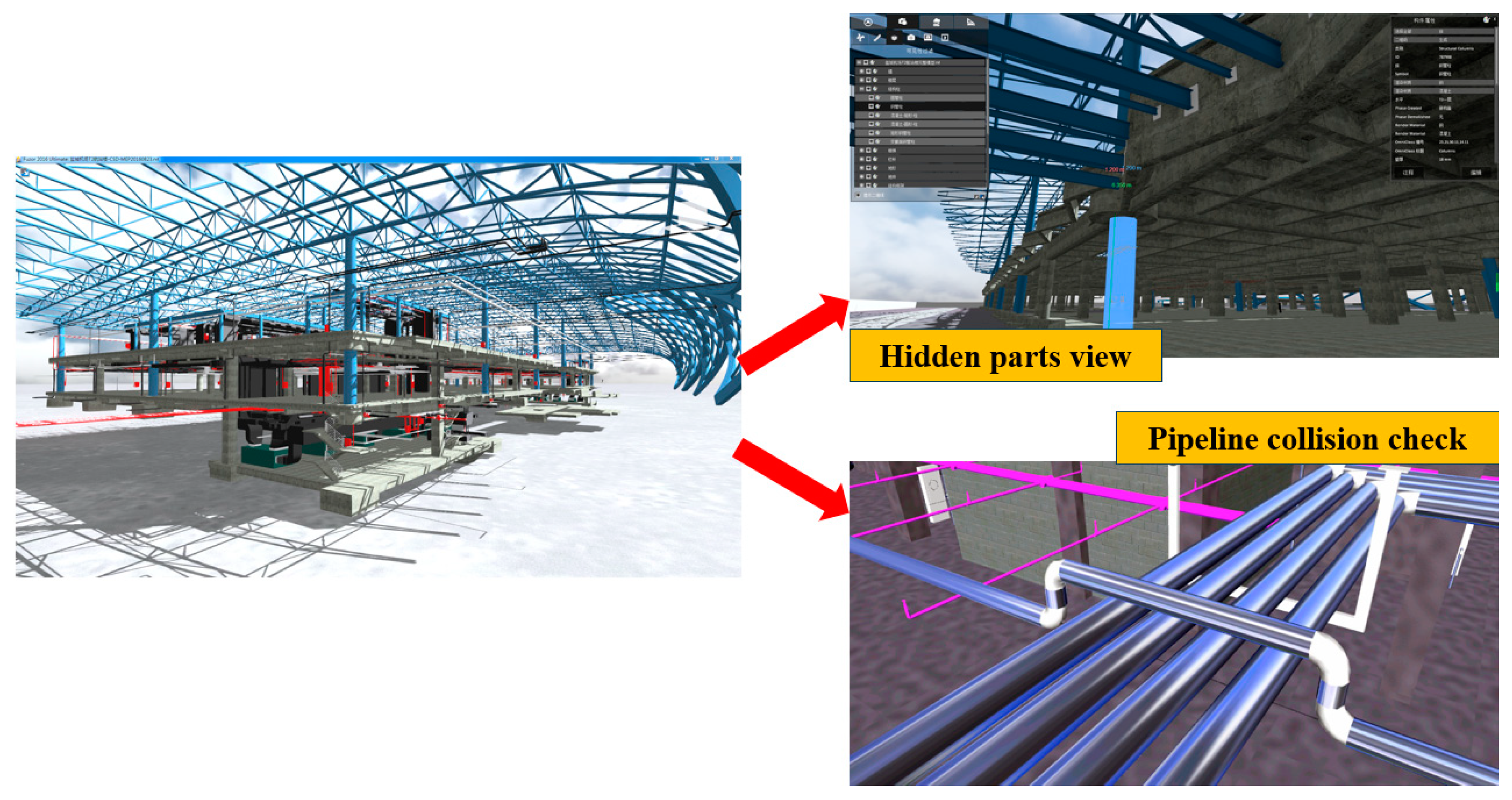
3.3. Application in MEP Engineering

The electric engineering of Yancheng Nanyang Airport terminal 2 includes an electricity distribution system, illuminating system, dynamical system, grounding system, fire warning system, diesel generator system, and USP power system. Water supply and drainage engineering includes domestic water supply and drainage systems, hot water systems, sewage systems, storm water systems, irrigation systems, and fire-fighting systems. The pumping room of domestic water and fire-fighting water is located in the energy center.
(a) In the planning phase, the mechanical and electrical BIM model was established based on the design drawings, which were integrated with the civil BIM model to conduct a preliminary layout of the comprehensive pipeline. When the pipeline layout is dense and cannot meet the net height requirements, the BIM model collision inspection can be checked in advance and feed back to the design. In the design proofreading stage, holes are reserved on structural beams, plates, walls, and other components in this area to facilitate the insertion of mechanical and electrical pipelines during the construction phase, thereby ensuring the realization of building functions, as shown in Figure 14.
(b) BIM deepening design and pipeline optimizing distribution is able to be realized based on a series factors such as the drawings provided by the design institute, the optimizing advices confirmed by the owners, the sample of equipment selection, actual situation in site, and codes of construction inspection. Figure 15 gives a typical BIM synthesis drawing. On the basis of this diagram, a reasonable pipeline segmentation can be conducted by solely labeling each segment. For this project, the principle of pipeline segmentation in the fabricated machine room is a component length of ≤6 m and a component width of ≤2 m, as shown in Figure 16. On account of the machine room pipeline segment diagram, the component prefabricated drawings are to be issued to provide guidelines of factory processing, as shown in Figure 17. On the step of BIM synthesis drawings, pipeline segment drawings, and component processing drawings, the recursive construction drawings integrating the time dimension, precision control, and deviation rectification theory can be completed by the feasibility design of recursive assembly construction. In the meantime, the rehearsal of construction is able to be implemented by BIM to guide the jobs of fabricated installation, as shown in Figure 18.
(c) Collaborative management will be conducted by integrating BIM models from every profession, meanwhile optimizing the synthesized arrangement of pipelines and inspecting their collision. As the project proceeds, any fault and rework during the construction stage will be reduced, as shown in Figure 19.
(d) Construction drawings of each profession: Based on the refined BIM model, required information will be extracted to make construction workers fully understand the intention of model and drawings. As a consequence, the construction in site can be organized in order, avoiding the conflict from cross operation, as shown in Figure 20.
(e) Optimize pipeline support hanger: In the process of pipeline optimization, the support hanger is optimized to avoid issues such as disorderly layout and inconsistent styles during construction, while also meeting the overall visual requirements of the pipeline. Specifically, BIM technology is used to adjust the elevation of pipelines, merge pipelines of the same elevation, and arrange them on the same layer. Through BIM simulation analysis, the optimal integrated support and hangers are selected so as to achieve the overall beauty of the pipeline and save space.
(f) BIM + AR mechanical and electrical pipeline acceptance: BIM + VR technology can realize high-precision verification between the BIM model and field entity, complete verification of spatial positions such as pipeline specifications and height, and then help high-quality acceptance of mechanical and electrical pipelines, as shown in Figure 21.

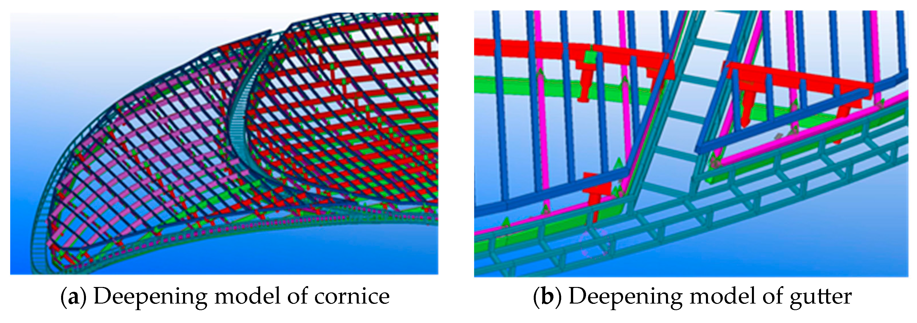
3.4. Application in Metal Roof Construction

The metal roof plan view size of airport terminal is 180 m × 72 m. The shape in longitudinal and transverse is a complex arc. The skylight is shaped by a complicated rhombus and triangle. The aluminum honeycomb board of cornice is hyperbolic in shape with a consistent abutted seam of open aluminum veneer. Every connection between the purlin and steel structure needs to be set out to confirm the coordination.
(a) Taking the joint deepening design as an example, the roof system in this project is a large-span special-shaped curved surface with complicated joints, increasing the difficulties of deepening the design. By employing BIM software combined with Tekla, a 3D deepening design model is able to be completed to solve the member collision and missing problem and to aid the guidance of construction, which the traditional 2D drawings are unable to easily realize, as shown in Figure 22.

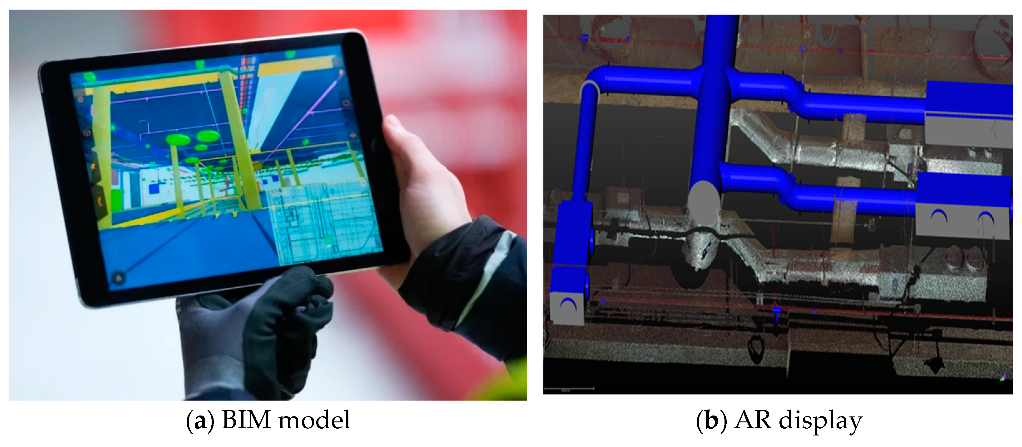
3.5. Application in Synergy

(a) Synergetic application in PC: BIM synergy in PC can help with net height analysis, security analysis, and opening analysis. Relevant report will be exported to settle potential safety problems and to enhance safety management. The BIM Fuzor function in PC will proceed a real-time collision check. Its results are going to be presented through marked points to relevant responsible personnel, not only simplifying the coordination procedure, but reducing the coordination cycle, as shown in Figure 23.
(b) Synergetic application in mobile terminal: BIM synergy in the mobile terminal will realize safety and quality control at the construction site. Relevant problems will be recorded and imported into the platform in time to urge relevant responsible personnel to perform a closed loop rectification. BIM mobile terminal devices make on-site model reviews possible. After comparing and amending, the consistency between the model and the actual on-site conditions will be ensured, providing references to the subsequent construction, as shown in Figure 24.

4. Conclusions

The main building of Yancheng Nanyang Airport terminal 2 consists of a steel roof structure, an exposed single-layer reticulated shell, and a metal roof with a tonnage of nearly 4000 t. The steel roof structure is a special-shaped curved surface. The length at the east–west axis is 216 m and 108 m at the north–south axis. The roof structure has a large span with challenging assembly problems. The exposed single-layer reticulated shell with welded rectangular box sections is a large-span hyperbolic shape, adding the difficulties of positioning installation on site. The concrete-filled steel tubular columns supporting the roof are special-shaped, calling for a higher requirement on the assembly precision on site. All these characteristics result in greater difficulties in the construction process for the airport terminal. The actual problems encountered in the construction are efficiently solved when all the construction processes and professionals are using BIM. In order to give a rational assignment of task, BIM modeling needs to be done prior to construction in order to provide visualizations of the complicated details. The assistance offered by BIM makes the project management run more smoothly. In addition to the application during the construction phase, BIM technology can also be used in other aspects. For example, completed BIM model at the time of project delivery contains all information, such as spatial data and technical performance reports of the facilities, which can effectively assist facility management agencies in facility maintenance and fault handling during the operation phase, and establish a performance reporting system during the operation and maintenance period, thereby achieving high-level facility operation and maintenance management and reducing the cost of facility operation and maintenance. Additionally, this paper can be treated as a good example of the combination of BIM and managing contractors.

Author Contributions

Conceptualization, L.Y. and L.Q.; methodology, Y.L.; investigation, W.Z.; resources, W.Z.; data curation, W.Z.; writing—original draft preparation, S.Y.; writing—review and editing, W.Z. and Y.Z.; visualization, S.Y.; supervision, S.Y. and Y.Z.; project administration, Y.L.; funding acquisition, S.Y. All authors have read and agreed to the published version of the manuscript.

Funding

This research was supported by China Postdoctoral Science Foundation, grant number 2022T150612.

Data Availability Statement

Data will be made available on request.

Conflicts of Interest

The authors declare no conflict of interest.

References

  1. McKinney, K.; Kim, J.; Fischer, M.; Howard, C. Interactive 4D-CAD. Comput. Civ. Eng. 1996, 20, 381–389. [Google Scholar]
  2. Collier County, E.; Fischer, M. Visual-Based Scheduling: 4D Modeling on the San Mateo Health conjunction with Center. In Proceedings of the Third Congress Held in A/E/C Systems, California, CA, USA, 17–19 June 1996; pp. 800–805. [Google Scholar]
  3. Froese, T.; Fischer, M.; Grobler, F.; Ritzenthaler, J.; Yu, K.; Akinci, B.; Akbas, R.; Koo, B.; Barron, A.; Kunz, J. Industry foundation classes for project management-a trial implementation. Inf. Technol. Constr. 1999, 4, 17–36. [Google Scholar]
  4. Kam, C.; Fischer, M.; Hanninen, R.; Karjalainen, A.; Laitinen, J. The product model and Fourth Dimension project. Inf. Technol. Constr. 2003, 8, 137–166. [Google Scholar]
  5. Marshall-Ponting, A.J.; Aouad, G. An nD modelling approach to improve communication processes for construction. Autom. Constr. 2005, 14, 311–321. [Google Scholar] [CrossRef]
  6. Adjei-Kumi, T.; Retik, A. A Library-Based 4D Visualization of Construction Processed. In Proceedings of the IEEE Conference on Information Visualization, London, UK, 27–29 August 1997; pp. 315–321. [Google Scholar]
  7. Rad, H.N.; Khosrowshahi, F. Visualization of Building Maintenance Through Time. In Proceedings of the IEEE Conference on Information Visualisation, London, UK, 27–29 August 1997; pp. 308–314. [Google Scholar]
  8. See, R. Building information models and model views. J. Build. Inf. Model. 2007, 2, 20–25. [Google Scholar]
  9. Tulke, J.; Hanff, J. 4D construction sequence planning-new process and data model. In Proceedings of the CIB-W78 24th International Conference on Information Technology in Construction, Maribor, Slovenia, 26–29 June 2007; pp. 79–84. [Google Scholar]
  10. Tory, M.; Swindells, C. Comparing ExoVis, Orientation Icon, and In-Place 3D Visualization Techniques. Graph. Interface 2003, 3, 57–64. [Google Scholar]
  11. Akinci, B.; Fischer, M.; Kunz, J. Automated generation of work spaces required by construction activities. J. Constr. Eng. Manag. 2002, 128, 306–315. [Google Scholar] [CrossRef]
  12. Sacks, R.; Treckmann, M.; Rozenfeld, O. Visualization of work flow to support lean construction. J. Constr. Eng. Manag. 2009, 135, 1307–1315. [Google Scholar] [CrossRef]
  13. Hewage, K.N.; Ruwanpura, J.Y. A novel solution for construction on-site communication-the information booth. Can. J. Civ. Eng. 2009, 36, 659–671. [Google Scholar] [CrossRef]
  14. Zhang, C.; Arditi, D. Automated progress control using laser scanning technology. Autom. Constr. 2013, 36, 108–116. [Google Scholar] [CrossRef]
  15. Kiviniemi, A.; Karlshøj, J.; Tarandi, V.; Bell, H.; Karud, O.J. Review of the Development and Implementation of IFC Compatible BIM.; Erabuild Funding Organization: London, UK, 2008. [Google Scholar]
  16. Building SMART Alliance of National Institute of Building Sciences. BIM Project Execution Planning Guide Version 1.0; The Computer Integrated Construction Research Program; Penn State College of Engineering: University Park, PA, USA, 2010; Available online: https://bim.psu.edu/downloads/ (accessed on 8 November 2023).
  17. Song, S.; Yang, J.; Kim, N. Development of a BIM-based structural framework optimization and simulation system for building construction. Comput. Ind. 2012, 63, 895–912. [Google Scholar] [CrossRef]
  18. Chen, L.; Luo, H. A BIM-based construction quality management model and its applications. Autom. Constr. 2014, 46, 64–73. [Google Scholar] [CrossRef]
  19. Ma, Z.; Cai, S.; Mao, N.; Yang, Q.; Feng, J.; Wang, P. Construction quality management based on a collaborative system using BIM and indoor positioning. Autom. Constr. 2018, 92, 35–45. [Google Scholar] [CrossRef]
  20. Pan, Y.; Zhang, L. Automated process discovery from event logs in BIM construction projects. Autom. Constr. 2021, 127, 103713. [Google Scholar] [CrossRef]
  21. Yilmaz, G.; Akcamete, A.; Demirors, O. BIM-CAREM: Assessing the BIM capabilities of design, construction and facilities management processes in the construction industry. Comput. Ind. 2023, 147, 103861. [Google Scholar] [CrossRef]
Figure 1. Yangcheng Nanyang Airport terminal 2 project diagram.
Buildings 13 02846 g001
Figure 2. Main structure of terminal 2 diagram.
Buildings 13 02846 g002
Figure 3. Site management based on BIM.
Buildings 13 02846 g003
Figure 4. Inconsistency between architectural and structural drawings of drainage ditch.
Buildings 13 02846 g004
Figure 5. The reinforcement collision problem in the process of steel column base hoisting.
Buildings 13 02846 g005
Figure 6. Prestressed reinforcement ring beam joint optimization.
Buildings 13 02846 g006
Figure 7. Masonry layout scheme simulation.
Buildings 13 02846 g007aBuildings 13 02846 g007b
Figure 8. Steel tubular column installation.
Buildings 13 02846 g008aBuildings 13 02846 g008b
Figure 9. Steel roof structure partition diagram.
Buildings 13 02846 g009
Figure 10. Roof steel structure construction process simulation.
Buildings 13 02846 g010aBuildings 13 02846 g010b
Figure 11. Subarea diagram of single-layer reticulated shell.
Buildings 13 02846 g011
Figure 12. Construction process simulation of single-layer reticulated shell.
Buildings 13 02846 g012aBuildings 13 02846 g012b
Figure 13. Fabrication data extraction for special-shaped members.
Buildings 13 02846 g013
Figure 14. The reserved hole on structural.
Buildings 13 02846 g014
Figure 15. Model of synthesis pipeline arrangement.
Buildings 13 02846 g015
Figure 16. Pipeline segment diagram.
Buildings 13 02846 g016
Figure 17. Prefabricated component processing diagram based on BIM.
Buildings 13 02846 g017
Figure 18. A grade control point, deviation rectification segment, and rehearsal of recursive construction process.
Buildings 13 02846 g018
Figure 19. Coordinated management of each profession.
Buildings 13 02846 g019
Figure 20. 3D Visual Interpretation of Design Intention.
Buildings 13 02846 g020
Figure 21. BIM + AR mechanical and electrical pipeline acceptance.
Buildings 13 02846 g021
Figure 22. Deepening design of metal roof joints.
Buildings 13 02846 g022
Figure 23. Synergetic platform in PC terminal.
Buildings 13 02846 g023
Figure 24. Synergetic platform on a mobile terminal.
Buildings 13 02846 g024
Disclaimer/Publisher’s Note: The statements, opinions and data contained in all publications are solely those of the individual author(s) and contributor(s) and not of MDPI and/or the editor(s). MDPI and/or the editor(s) disclaim responsibility for any injury to people or property resulting from any ideas, methods, instructions or products referred to in the content.

