Article

Large-Strain Nonlinear Consolidation of Sand-Drained Foundations Considering Vacuum Preloading and the Variation in Radial Permeability Coefficient

1
College of Civil Engineering, Hunan City University, Yiyang 413000, China
2
School of Civil Engineering, Hunan University, Changsha 410000, China
3
Hunan Engineering Research Center of Structural Safety and Disaster Prevention for Urban Underground Infrastructure, Yiyang 413000, China
4
Hunan Engineering Research Center of Development and Application of Ceramsite Concrete Technology, Hunan City University, Yiyang 413000, China
5
Power China Zhong Nan Engineering Corporation Limited, Changsha 410082, China
6
School of Civil Engineering, Henan Institute of Engineering, Zhengzhou 451191, China
*
Author to whom correspondence should be addressed.
Buildings 2023, 13(11), 2843; https://doi.org/10.3390/buildings13112843
Submission received: 18 August 2023 / Revised: 12 October 2023 / Accepted: 6 November 2023 / Published: 14 November 2023
(This article belongs to the Section Building Structures)

Abstract

:
The vacuum preloading method effectively strengthens soft soil foundations with vertical drainage, which produces a smear effect when laying sand drains. Meanwhile, the seepage of pore water and soil deformation during consolidation exhibit nonlinear characteristics. Therefore, based on Gibson’s 1D large-strain consolidation theory, this paper developed a more generalized large-strain radical consolidation model of sand-drained soft foundations under free-strain assumptions. In this system, the double logarithmic compression permeability relationships for soft soils with large-strain properties, the variation in the radical permeability coefficient in the smear zone, and the effect of the non-Darcy flow were all included. Then, the partial differential control equations were numerically solved by the finite difference method and validated with existing radical consolidation test results and derived analytical solutions. Finally, the influences of relevant model parameters on consolidation are discussed. The analysis shows that the greater the maximum dimensionless vacuum negative pressure P0, the faster the consolidation rate of sand-drained foundations. Meanwhile, the decrease in the negative pressure transfer coefficient k1 will result in a decreasing final settlement amount. Moreover, the consolidation rate of sand-drained foundations is slower considering the non-Darcy flow, but the final settlement is unaffected.

1. Introduction

The vacuum preloading method is one of the most effective methods to treat soft soil ground with the drainage consolidation method. Its principle aim is to produce negative pressure in the soil as a load through vacuum pumping, and then the water in the soil pores is drained so that the ground soil is consolidated and the strength is improved. Meanwhile, combined with vacuum pressure, the load can be quickly applied at once, with fast reinforcement speed and a short construction period. Previous studies [1,2,3,4] have shown that the vacuum preloading method will produce large deformations when dealing with soft soils with large void ratios, and the permeability coefficient decreases with the decrease in the soil–void ratio. Meanwhile, the construction disturbance of the installed sand drain produces a smear effect, so the variation in the radical permeability coefficient within the smear zone should also be considered. Meanwhile, it is also indisputable that water seepage in soft clay deviates from Darcy’s flow [5,6,7]. Therefore, a more generalized large-strain nonlinear consolidation model of soft soil foundations with sand drains is established in this paper, considering the coupled effect of the nonlinear compression relationship and permeability relationships, the variable permeability coefficient in the smear zone, and the non-Darcy flow effect. It is expected to simulate the radial drainage consolidation of deep clayey foundations more truly.
For the study of vacuum preloading on sand-drained foundations, relevant scholars have conducted much research and achieved rich results [8,9,10,11,12]. Among them, studies [8,9] developed Terzaghi’s 1D consolidation system, incorporating vacuum preloading. Chai et al. [10] established a method for estimating the final vacuum pressure distribution and proposed the corresponding model for the vacuum-drain consolidation-induced settlement curves. Indraratna et al. [11] and Geng et al. [12], respectively, deduced an analytical solution for vertical drain consolidation foundations with linear attenuation of vacuum preloading: conventional and point array vacuum preloading. However, these studies have neglected the large-strain consolidation characteristics of soft clayey soils, and research reveals that the small-strain theory would not be suitable for highly compressible soil, such as soft clayey soils with large-stain properties [13,14]. In this regard, McVay et al. [15] investigated large-strain nonlinear consolidation of sand-drained foundations in clay by assuming that the void ratio varies exponentially with effective stress. Perera et al. [16] derived a large-strain consolidation analytical solution for vacuum preloading incorporating the semi-logarithmic nonlinear compression relationship and soil disturbance. Geng et al. [17] and Nguyen et al. [18] respectively studied the nonlinear large-strain consolidation of sand-drained foundations considering self-weight and well resistance decay over time by using a semi-logarithmic relationship (i.e., e lg σ and e lg k ). Walker et al. [19] presented an approximate solution for the consolidation of sand-drained foundations considering smear zone overlap. In more in-depth research, R. Butterfield [20] proposed to apply double logarithmic compression and permeability relationships (i.e., Equations (2) and (3)) to analyze the consolidation problem and pointed out that the double-logarithmic form of relationships can be well-consistent with the test results for soft clayey soils under a large-strain scenario. Tavenas et al. [21] also demonstrated that the semi-logarithmic form of relationships only satisfies linear relationships in low-strain categories below 20%. Based on double logarithmic compression and permeability relationships, Li et al. [22] initially developed the 1D large-strain consolidation for soft ground and derived the corresponding analytical solutions. However, the above studies on sand-drained foundation consolidation often assume that pore water seepage in the soil is consistent with Darcy’s flow.
In terms of numerical methods in large-strain problems, compared with common, familiar numerical methods such as the finite element method and finite volume method, the finite difference method is more popular and widely used. In addition, in recent years, the use of meshless methods for complex nonlinear partial differential problems has gradually gained the favor of scholars [23,24,25,26]. This type of method has significant advantages in dealing with some special problems, such as simulating large deformation problems, and can be one of the key research directions for future numerical methods.
According to the research results of indoor tests [5,6,7], it was found that pore water seepage exhibited nonlinear characteristics under low hydraulic gradients. Among them, considering the non-Newtonian fluid characteristics of soil, Swartzendurber [6] summarized different regions’ minor data and proposed a continuous mathematical expression flow rule with only two flow parameters. This flow relationship could fit well with the test data and easily be applied in practical engineering. Based on this, scholars [27,28] have conducted a 1D consolidation considering this flow relationship and obtained a more generalized understanding of 1D consolidation characteristics.
In summary, although the research on sand-drain consolidation under vacuum preloading has achieved certain results, the influence of the nonlinearity compression and permeability relationships, the radical permeability coefficient variation, and non-Darcy flow still have not been considered simultaneously. Therefore, based on Gibson’s [13] 1D large-strain consolidation theory and Barron’s [29] free-strain assumption, an improved large-strain vacuum preloading consolidation equation of soft ground with sand drain is established and solved by the finite difference method. The double logarithmic compression and permeability relationships for large voids ratio to soft clays, the three different permeability variation modes in the smear zone, and the non-Darcy flow with continuous function form were also included in this system. Based on the proposed vertical drain model solutions, relevant parameters affecting the consolidation of soft foundations with sand drains are further analyzed.

2. Large Radical Strain Consolidation Model with Sand Drains

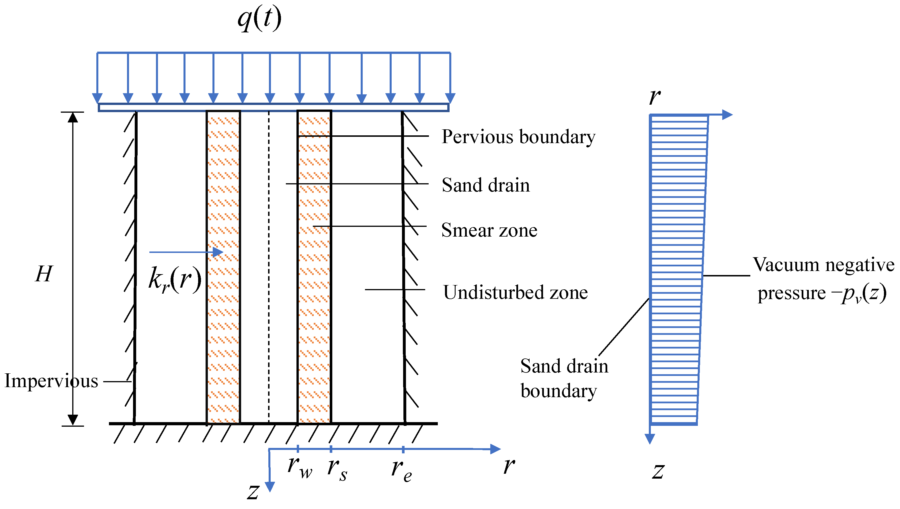
2.1. Problem Description

As shown in Figure 1, assuming the thickness of sand-drained foundations is H, a sand drain is installed in the foundation for drainage consolidation. Considering the smear effect caused by construction disturbance, the whole influence area of radial seepage is divided into a smear zone and an undisturbed zone. The radius of the sand drain, smear area, and influence area are rw, rs, and re, respectively. r and z denote the radial and vertical coordinates, respectively, and −pv(z) is the vacuum negative pressure acting on the sand-drain zone. The edge of the sand drain is a fully pervious boundary, and the outermost periphery of the weak smear area is an impermeable boundary. q(t) is the overload load on the foundation surface (see Figure 2), where t1 is the completion of the single-loading time, q0 is the initial load value, and qu is the final value.

2.2. Basic Assumptions

To facilitate the solution, the following assumptions are made on the basis of Gibson’s 1D large deformation consolidation theory and Barron’s free-strain consolidation theory:
(1)
The soil particles only move vertically, and the radical geometric deformation is ignored.
(2)
Carrillo [30] concluded that the consolidation of sand-drained foundations can be decomposed into radial and vertical seepage for calculation, making the radial consolidation theory more practical. Therefore, in parallel with the existing research [29], only radical seepage is considered in the process of soft foundations with sand-drain consolidation.
(3)
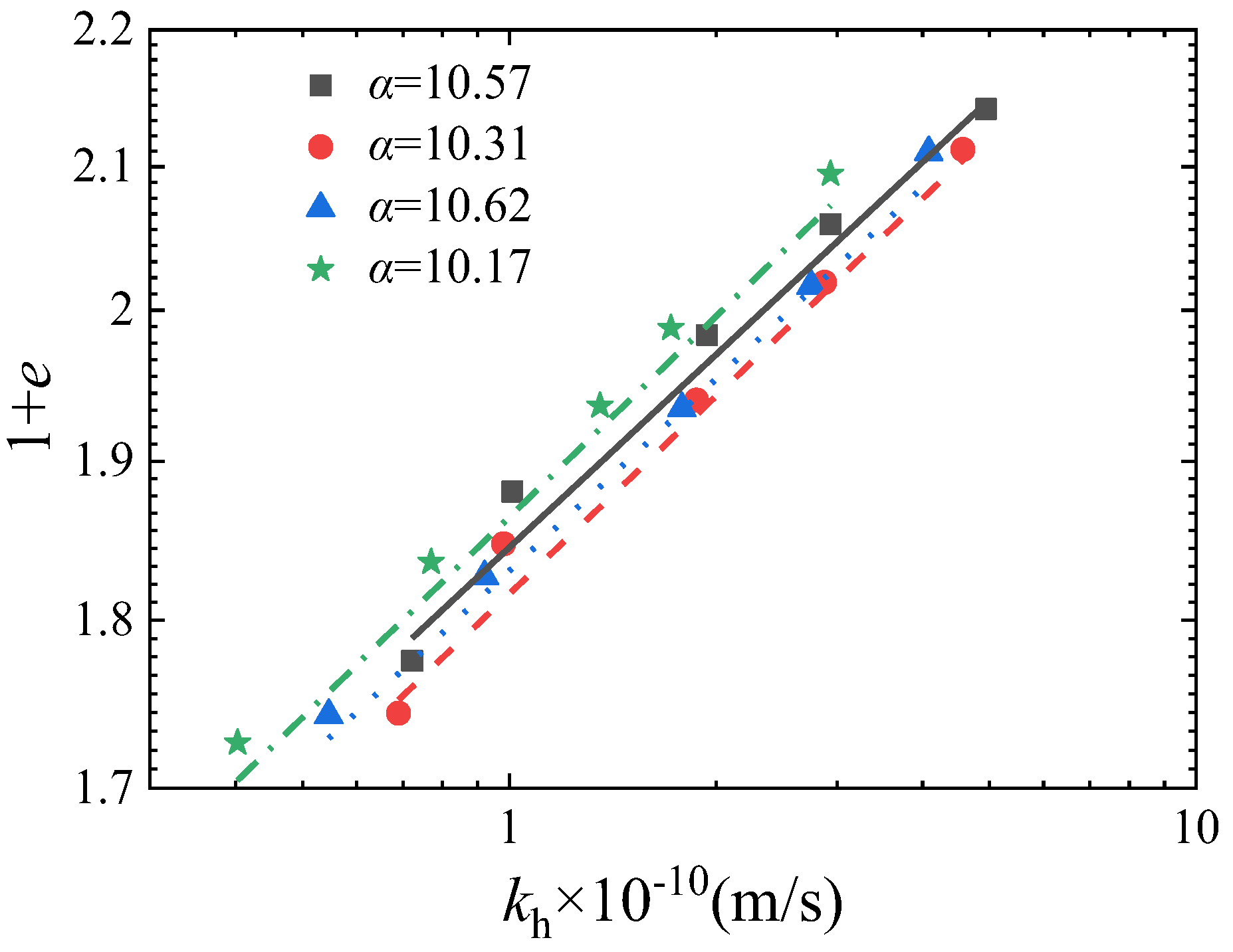
As shown in Figure 3, it is assumed that the seepage of pore water corresponds to the non-Newtonian index flow [6], which is:
v = k r [ i i 0 ( 1 e i / i 0 ) ]
where v is the seepage velocity; i is the hydraulic gradient; kr is the radial permeability coefficient; i0 is the non-Newtonian index.
The nonlinear relationship of soft soils can be simulated by the double logarithmic compression and permeability relationship proposed by R. Butterfield (1979) [20], i.e.,
lg ( 1 + e ) lg ( 1 + e 0 ) = I c ( lg σ 0 lg σ )
lg ( 1 + e ) lg ( 1 + e 0 ) = 1 α ( lg k r lg k r 0 )
where e0 and e are the initial void ratio and the void ratio at any time, respectively. σ 0 and σ′ are the initial effective stress and the initial effective stress at any time. kr is the radical permeability coefficient at the radius of the undisturbed area at any time, and kr0 is the initial radical permeability coefficient. Ic is the slope of the lg(1 + e) − lg σ′ linear relationship, α is the reciprocal of the slope of the linear relationship lg(1 + e) − lg kr. For convenience, Ic and α are expressed by the compression index and permeability index.
(4)
Suppose the vacuum negative pressure at the sand well boundary changes from −p0 to −k1p0 along the depth, i.e., Equation (4):
p v ( z ) = p 0 [ 1 ( 1 k 1 ) z H ]
where p0 is the vacuum preloading value at the foundation’s top surface, k1 is the negative pressure transfer coefficient, and its value is not greater than 1.
Considering the variation in the initial radial permeability coefficient along the radial direction within the smear zone, i.e., the smear effect due to the construction disturbance. That is, letting kr(r) = krf(r) and assuming three variation modes of radial permeability coefficient, as shown in Figure 4. Mode 1 is the radical permeability coefficient that keeps constant at the smear zone; modes 2 and 3 assume that the radical permeability coefficient increases linearly and parabolically with the increase in radial radius r of the zone, respectively.
Equations (5)–(7) are mathematical functional relations of modes 1, 2, and 3, respectively.
Mode 1:
f ( r ) = { δ , r w r r s 1 , r s < r r e
Mode 2:
f ( r ) = r r w r e r w ( 1 δ ) + δ ,     r w r r e
Mode 3:
f ( r ) = { ( 1 δ ) ( a 1 b 1 + c 1 r r w ) ( a 1 + b 1 c 1 r r w ) , r w r r s 1 , r s < r r e
where a 1 = 1 / 1 δ , b 1 = s / ( s 1 ) , c 1 = 1 / ( s 1 ) , s = r s / r w , δ = ks/kr.

2.3. Control Equations

According to the above basic assumptions and the continuous flow conditions of radial sand-drain drainage consolidation, there are:
v r + v r = 1 1 + e e t
Meanwhile, Equation (2) can be transformed to:
e = ( 1 + e 0 ) ( σ 0 σ ) I c 1
By taking the partial derivative of Equations (9) and (1) into Equation (8), we can obtain:
1 r r ( r k r ( r ) u γ w r ) = I c σ 0 σ 0 σ ¯ ( q ( t ) t u t )
Combining Equations (2) and (3) gives:
k r k r 0 = ( σ 0 σ ) α I c
Bringing Equation (11) into Equation (10), we can obtain:
σ 0 k r 0 I c ( σ σ 0 ) { f ( r ) r ( σ σ 0 ) α I c [ u γ w r i 0 ( 1 e 1 i 0 u γ w r ) ] + r [ f ( r ) ( σ σ 0 ) α I c [ u γ w r i 0 ( 1 e 1 i 0 u γ w r ) ] ] } = u t q ( t ) t
The corresponding boundary conditions are:
{ u ( r w , z , t ) = p v ( z ) u r r | r = r e = 0 u ( r , z , 0 ) = q ( 0 )

3. Solution of Equations

3.1. Dimensionless Parameters

To facilitate the solution, dimensionless processing is performed:
S = σ 0 σ 0 ,   Q = q ( t ) σ 0 ,   U = u σ 0 ,   P 0 = p 0 σ 0 ,   T v = C v 0 t 4 r e 2 ,   T v 1 = C v 0 t 1 4 r e 2 ,   C v 0 = k r 0 σ 0 γ w I c ,   I 0 = i 0 γ w r e σ 0 ,   R = r r e ,   R s = r s r e ,   R w = r w r e ,   Z = z H , P ( Z ) = p v ( z ) σ 0
By introducing the above dimensionless equation into control Equation (13), we can obtain:
1 R ( S + Q U ) α I c + 1 [ U R I 0 ( 1 e 1 I 0 U R ) ] + ( S + Q U ) R [ ( S + Q U ) α I c ( U R I 0 ( 1 e 1 I 0 U R ) ) ] = U T Q T
The dimensionless form of the boundary conditions is as follows:
{ U ( R w , Z , T v ) = P ( Z ) u r r ( 1 , Z , T v ) = 0 U ( R , Z , 0 ) = Q 0

3.2. Differential Control Equations

The soil layer is divided into n equal parts along the radial direction, each equal part is divided into ΔR, the vertical direction is divided into m equal parts, each equal part is divided into ΔZ, and then the time is discretized by the ΔTv. The Equation (15) can be discrete as:
U i , m j + 1 = U i , b j + Q j + 1 Q j + Δ T v R i α i , b j β i , b j [ A i , b j I 0 ( 1 e A i , b j I 0 ) ] + Δ T v Δ R [ α i , b j β i + 1 / 2 , b j ( A i + 1 / 2 , b j I 0 ( 1 e A i + 1 / 2 , b j I 0 ) ) α i , b j β i 1 / 2 , b j ( A i 1 / 2 , b j I 0 ( 1 e A i 1 / 2 , b j I 0 ) ) ]
in which i, j, and b are the number of radial space nodes, time nodes, and vertical space nodes: R i = R w + i Δ R , α i , b j = ( S + Q j U i , b j ) , β i , b j = ( S + Q j U i , b ) α I c , A i , b j = U i + 1 , b j U i 1 , b j 2 Δ R , A i + 1 / 2 , b j = U i + 1 , b j U i , b j Δ R , A i 1 / 2 , b j = U i , b j U i 1 , b j Δ R .
Boundary condition Equation (14) can be discretized as:
{ U 0 , b j = P 0 [ 1 ( 1 k 1 ) ( b Δ Z ) ] U n + 1 , b j = U n 1 , b j U i , b 0 = Q 0
Equations (17) and (18) constitute a closed system of equations, which can obtain the excess pore water pressure at any time and depth by iteration calculation. Meanwhile, for soil layers with a thickness of H, the settlement St at the moment of Tv can be expressed as:
S t = 0 H r w r e 2 r r e 2 r w 2 ( e 0 e ) ( 1 + e 0 ) d r dz
Substituting Equation (9) into Equation (19) discretely gave:
S t = b = 0 m 1 G ( b , T v ) + G ( b + 1 , T v ) 2
where G ( b , T v ) = i = 0 n 1 R i ( 1 ( S + Q U i , b ) I c ) + R i + 1 ( 1 ( S + Q U i + 1 , b ) I c ) ( 1 + R w ) n .
The degree of consolidation Us defined by deformation is:
U s = S t S × 100 %
In addition, the average consolidation degree Up defined by the pore pressure of the soft foundation with sand drains is:
U p = 1 0 H r w r e 2 π r u d r z d z 0 H r w r e 2 π r q u d r d z = 1 0 1 R w 1 R U d R d Z 0 1 R w 1 R Q u d R d Z = 1 b = 0 m 1 i = 0 n 1 Y i , b + i = 0 n 1 Y i , b + 1 ( 1 R w 2 ) Q u
where Y i , b = U i , b R i + 1 U i + 1 , b R i 2 Δ R ( R i + 1 2 R i 2 ) + U i + 1 , b U i , b 3 Δ R ( R i + 1 3 R i 3 ) .

4. Solution Verification

4.1. Verification with an Indoor Radial Penetration Test

Herein, the average consolidation degree defined by the settlement is compared with the indoor radial consolidation test results of Indraratna et al. [11] to verify the reliability of the proposed finite difference solutions.
The proposed system parameters need to be degraded to ensure the proposed model is consistent with the indoor test conditions. That is, reducing the proposed model with Darcy’s flow and 0 vacuum preloading scenario, i.e., I0 = 0.00001, P0 = 0 kPa. Meanwhile, the loading mode is set as constant loading, and the variation mode of the radial permeability coefficient takes mode 1 and δ = 2 / 3 . Moreover, as shown in Figure 5 and Figure 6, the four sets of original data given by laboratory tests are re-fitted in the double logarithmic coordinate systems, i.e., determining Ic = 0.061 and α = 10.42. Other parameters are consistent with the test results, as summarized in Table 1. Then, the degree of consolidation defined by the settlement is calculated according to Equation (21) and compared with the indoor monitored data, as shown in Figure 7. As observed, the consolidation degree Us(%) calculated theoretically is in good agreement with the settlement results monitored by laboratory tests, preliminarily verifying the reliability of the proposed solutions.

4.2. Verification with Analytical Solutions under Equal Strain Assumption

Since there is currently no analytical solution for the large-strain sand-drained foundations under a double-logarithmic coordinate system, the analytical solution of equal strain is derived in this section by referring to the consolidation solution of the sand-drained foundations under equal strain conditions derived by Xie et al. [31]. The derived analytical solution assumption is consistent with the above-mentioned assumptions, except that it satisfies the equal strain assumption. For the sake of simplification, it is reduced to not considering the variation in radical permeability coefficient; that is, selecting the radical change in the permeability coefficient of the smear zone as mode 1, so that δ = 1, α = 0. Meanwhile, it degenerates into Darcy’s flow with I0 = 0, and the loading mode is instantaneous loading. The boundary conditions, model parameters, and corresponding dimensionless variables are consistent with those mentioned above. Then, the radial consolidation equation is:
1 r r ( r k r 0   u γ w r ) = m v u ¯ t = 1 1 + e d e d σ ¯ u ¯ t
where mv is the volume compression coefficient, u ¯ is the average excess pore pressure of the sand-drained foundations, and the expression u ¯ is as follows:
u ¯ = 1 ( r e 2 r w 2 ) 0 H r w r e 2 r u d r d z
Bringing Equation (9) into Equation (24) gives:
1 r r ( r k r 0   u s γ w r ) = I c σ 0 ( σ 0 σ ¯ ) u s ¯ t
Combining Equation (14) and integrating both sides of Equation (25) yields:
u s r = σ 0 C v 0 σ ¯ u s ¯ t r e 2 r 2 2 r
Combining Equation (14) and integrating both sides of Equation (26) then gives:
u = ( σ 0 2 C v 0 σ ¯ u s ¯ t ) ( r e 2 ln r r e 2 ln r w r 2 r w 2 2 ) p v ( z )
Bringing Equation (27) into Equation (24):
u ¯ = ( σ 0 2 C v 0 σ ¯ u s ¯ t ) G 1 2 p 0
where G = ( r e 4 ln r e r e 4 ln r w 3 r e 4 4 r w 4 4 + r e 2 r w 2 r e 2 r w 2 ) .
Separating the variables in Equation (28) yields:
u s ¯ t = 2 C v 0 ( σ 0 ¯ + q u u ¯ ) σ ¯ ( u ¯ + p 0 ) G
Integrating t on both sides of Equation (31) gives:
u ¯ = σ 0 ¯ + q u σ 0 ¯ ( σ 0 ¯ + q u + p 0 / 2 ) σ 0 ¯ + ( q u + p 0 / 2 ) e 2 ( σ 0 ¯ + q u + p 0 / 2 ) C v 0 σ 0 ¯ G t
The degree of consolidation defined by excess pore water pressure is:
U p = 1 u ¯ q u
Substituting Equation (30) into Equation (31) and making it dimensionless then gives:
U p = 1 u ¯ + p 0 / 2 q u + p 0 / 2 = 1 Q + P 0 / 2 + 1 + Q + P 0 / 2 ( Q + P 0 / 2 ) ( 1 + ( Q + P 0 / 2 ) e M )
where M = 8 ( 1 R w 2 ) ( 1 + Q + P 0 2 ) T v / ( n 1 R w 3 4 R w 4 4 + R w 2 ) .
The dimensionless parameters S = 1, Q =10, Rw =0.2, ΔR = 0.01, ΔTv = 10−6, and P0 = 5 are selected to verify the results obtained by finite difference solutions with the analytical solution under equal strain assumption. According to the comparison of solutions under the assumptions of equal strain and free strain given by Li [32], the impact of the two extreme assumptions on the consolidation of sand drains is mainly reflected in the early stage of consolidation. That is, the degree of consolidation obtained under the assumption of free strain is greater in the early consolidation stage but gradually reduces over time. As seen, the results shown in Figure 8 are consistent with this, further verifying the reliability of the proposed numerical solutions.

5. Parametric Analysis

In this part, the corresponding influencing factors of the proposed soft soil consolidation system with sand drain were analyzed, including the change modes of the radial permeability coefficient, the Ic and α obtained by linear fitting in the double-logarithmic compression and permeability logarithmic coordinates, and seepage parameter i0 in non-Darcy flow rule. To facilitate the calculation, and if there is no special statement, the basic parameters for the calculation and analysis of the sand-drained foundations are as follows: Rw = 0.2, Rs = 0.6, σ0′ = 10 kPa, q0 = 50 kPa, qu = 100 kPa, ΔR = 0.01, P0 = 5, I0 = 1, Ic = 0.1, α = 10, δ = 2/3, ΔTv = 10−6, ΔZ = 0.05, k1 = 0, H = 1 m, the radial permeability coefficient variation mode is taken as pattern 1, and the loading mode is constant loading.

5.1. Excess Pore Water Pressure Distribution Analysis

Figure 9 and Figure 10 present the distribution curves of excess pore water pressure at Z = 0.5 under different loading modes when the dimensionless vacuum preloading value P0 = 5 and 20, respectively. As observed, the excess pore pressure curves under instantaneous loading are smaller than the linear loading values. The slower the linear loading rate, the greater the corresponding excess pore water pressure values. In addition, by comparing Figure 9 and Figure 10, it can be observed that an increase in vacuum pressure simultaneously reduces the excess pore pressure values at the same location. The pore pressure at dimensionless radius R = 0.2 is the vacuum negative pressure value, while the pore pressure in other radical places gradually approaches the vacuum negative pressure over time. That is to say, the vacuum negative pressure is the final excess pore water pressure value, essentially at the completion of sand-drained foundation consolidation under vacuum preloading.
Figure 11 shows the excess pore pressure distribution at the intermediate soil layer (i.e., Z = 0.5) under three radial permeability coefficient variation modes. Meanwhile, Figure 12, Figure 13 and Figure 14 depict the excess pore pressure distribution curves along the radial radius r at the intermediate soil layer under a different compression index (Ic), permeability index ( α ), and seepage parameter (I0), respectively. It can be seen from Figure 11 that the pore pressure value in mode 1 is the highest, followed by mode 2, and that mode 3 is slightly lower than mode 2. That is to say, the consolidation rate is the fastest in the parabolic variation mode of the radial permeability coefficient within the smear zone, followed by the linear variation mode, and the slowest in the constant variation mode. Further, it can be seen that, with the increase in the compression index, permeability index, and non-Newtonian index, the excess pore pressure curve values all increase under the same radical locations. That is to say, the larger the compression index, permeability index, and non-Newtonian index, the slower the excess pore pressure dissipation proceeding the sand-drained foundations.

5.2. Analysis of Average Consolidation Degree and Settlement

Figure 15 shows the influence curves of three radial permeability coefficient variation modes on average consolidation and soil settlement. As seen, the permeability coefficient of the smear area shows a parabolic change, and the consolidation rate is the fastest (mode 3). And in mode 1, where the permeability coefficient of the smear zone is constant, the consolidation rate is the slowest. In essence, when the permeability coefficients within the undisturbed zone are the same, the larger the average permeability coefficient of the smear zone is, the larger the whole consolidation rate of the sand-drained foundations will be. For the sand-drained foundations’ settlement, although the final settlement amount achieved by the three modes is consistent, mode 3 takes the shortest time to reach the same settlement amount under settlement proceeding, and mode 1 takes the longest time. As a further comparison with mode 1, mode 2 has a maximum relative deviation of 32.1% for the average consolidation degree and 18.9% for soil settlement compared to mode 1, and the maximum relative deviation of the two consolidation indexes in mode 3, respectively, reached 47.8% and 29.6% compared to mode 1. That is to say, different radical permeability coefficient modes within the smear zone still have a significant impact on the consolidation rate of the sand-drained foundations, which also indicates that the permeability modes should be reasonably adopted in practical engineering.
Figure 16 shows the influence curves of the top surface dimensionless vacuum negative pressure P0 on the radial consolidation of sand-drained foundations under different loading modes. As seen, the maximum vacuum negative pressure has a relatively minor impact on the consolidation rate of sand-drained foundations under instantaneous loading. For sand-drained foundations under single-stage loading, the larger the top surface vacuum negative pressure is, the faster the consolidation rate will be. Moreover, with the increase in the dimensionless single-stage loading completion time, Tv1, the influence of the top surface vacuum negative pressure on the consolidation rate becomes larger. Therefore, it can be concluded that, for actual soft foundation treatment projects with longer loading duration, more attention should be paid to the impact of vacuum preloading on the consolidation rate.
Li and Qiu’s [22] work has shown that the compression index (Ic) and permeability index (α) have the most concentrated range of variation, ranging from 0.08 to 0.12 and concentrated between 6 and 14, respectively, so this section adopts Ic = 6, 10, 14 and α = 0.08, 0.1, 0.12 for analysis. Figure 17 and Figure 18 show the influence of the average consolidation degree and settlement with time factor under different compression index (Ic) and permeability index (α) values. As observed, the whole consolidation rate slows with the increase in the compression index or permeability index. As for the settlement amount, the compressive index has little influence on the settlement amount at the early consolidation stage. However, as time goes on, the larger the compression index, the more significant the settlement at the same time, and the final settlement also becomes more significant. Meanwhile, with the increase in the permeability index (α), the time to reach the same settlement amount decreases, but the final settlement amount is unaffected. Nevertheless, it also should be noted that, compared to α = 6, the maximum relative deviation of consolidation degree reached 54.9% at α = 10, and it reached as high as 76.6% when α = 14. This indicates that although the permeability index, α, does not affect the final settlement, it has a significant impact on the whole consolidation process.
Figure 19 shows the average consolidation degree Up corresponding to a different drain spacing ratio n, n = re/rw. As can be seen, the radial consolidation rate decreases with an increase in the drain spacing ratio. Especially when n is greater than 40, the ratio has little influence on the consolidation rate. This also means that foundation soil beyond a certain range will not be affected by the spacing ratio n, which reflects that the range of the influence zone is limited. Therefore, in practical engineering, for rapid drainage and soft foundation consolidation with sand drains, the spacing of the drains should be reasonably arranged; n less than 40 is recommended.
Figure 20 illustrates the influence curves of the seepage parameter I0 on the average degree of consolidation, Up, and foundation settlement, St, at I0 = 0, 1, 3, and 5. As seen, the consolidation and settlement rate with Darcy’s flow (I0 = 0) is faster than that of the non-Newtonian index flow, and the whole consolidation and settlement rate becomes slower as I0 increases. For example, the corresponding Up values for increasing I0 are 58.61%, 69.33%, 79.74%, and 86.29%, respectively, and the maximum relative deviation reached 38.2% when I0 = 5 compared with Darcy’s flow. Therefore, without considering the influence of the non-Newtonian index flow, the consolidation and settlement rates of the sand-drained foundation will both be overestimated. Moreover, the settlement curves tend to be the same with time at different seepage parameters, I0, indicating that the non-Darcy flow does not influence the final settlement.
Figure 21 shows the average consolidation and settlement curves under different negative pressure transfer coefficients k1. It can be found that the change in k1 has almost no effect on the whole consolidation degree of the sand-drained foundations. In contrast, the k1 undeniably impacts foundation settlement at the middle and late consolidation stages. As seen, the soil settlement rate and final settlement decrease with the decrease of k1, indicating that the long settlement deformation of actual engineering should also be paid more attention under vacuum preloading scenarios.

6. Limitations

In this study, a developed large-strain consolidation system has been presented by considering vacuum preloading, double-logarithmic compression permeability relationships, the non-Darcy flow effect, and the radial permeability coefficient variation. Nevertheless, both the vertical seepage of pore water and soil rheological properties during the consolidation process cannot be reflected in the system. Therefore, the simplified assumptions can be further improved by incorporating the effects of vertical seepage and rheological model relationships to reveal more realistic soil creep consolidation behavior [33,34,35]. Additionally, the complex boundary and initial conditions of stone column-improved soft clay [36,37,38] combined with the vacuum preloading method can also be an essential research branch for larger-strain consolidation of sand-drained foundations.

7. Conclusions

In this paper, an improved large-strain consolidation system of soft foundations with sand drain is established considering vacuum preloading, double-logarithmic compression permeability relationships, and the non-Darcy flow effect. The finite difference method was used to solve it, and the validity of the numerical solution of the model was verified. Based on this, the consolidation behavior of sand-drain-improved soft foundations was deeply explored, and the following main conclusions were obtained:
(1)
The larger the average permeability coefficient of the smear area, the greater the consolidation rate of the sand-drained foundations. Compared with the constant permeability coefficient, when the permeability coefficient of the smear area changes linearly, the maximum relative deviations of consolidation degree and settlement amount reach 32.1% and 18.9%, respectively. When the permeability coefficient of the smear area changes in a parabolic manner, the maximum relative deviations between the degree of consolidation and the settlement amount reach 47.8% and 29.6%, respectively.
(2)
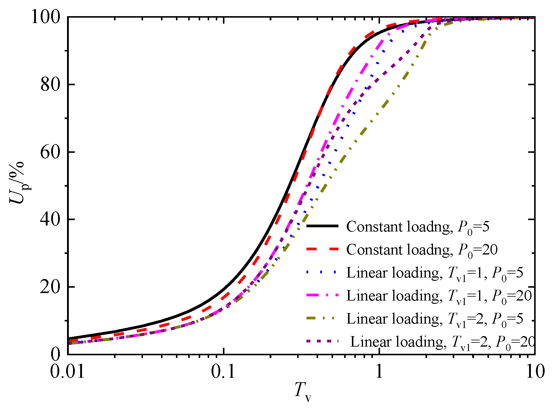
The greater the maximum dimensionless vacuum negative pressure, P0, the faster the consolidation rate of sand-drained foundations. Meanwhile, the more extended the loading duration, the greater the influence of vacuum negative pressure on the consolidation rate. This indicates that, in practical engineering projects that need to ensure foundation stability and fast consolidation, the vacuum preloading value can be adjusted promptly based on the proceedings of the construction period.
(3)
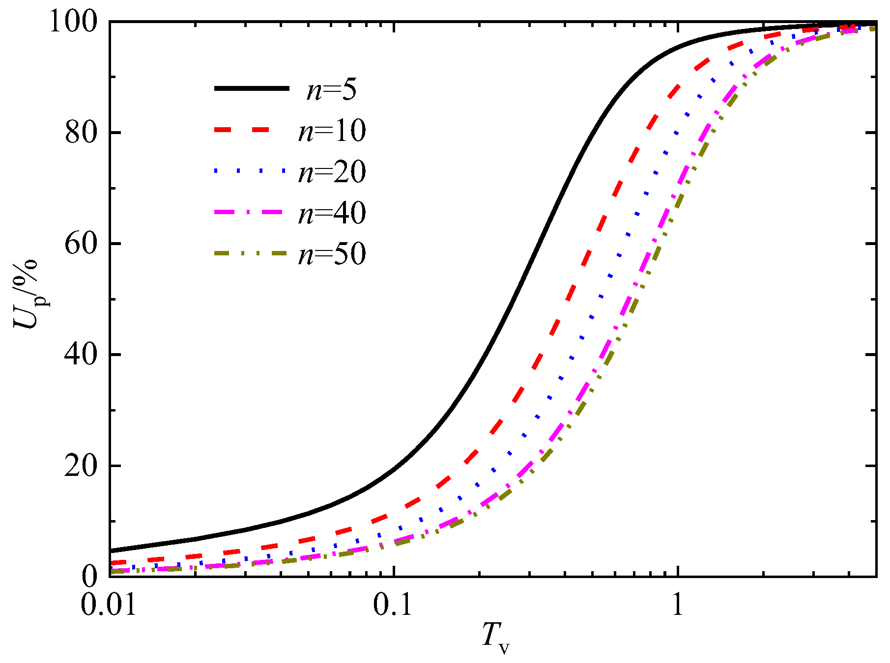
With an increase in the drain spacing ratio, n, the consolidation rate of soft foundations with sand drains decreases. Especially when the diameter ratio n > 40, increasing the healthy diameter ratio has little effect on the consolidation rate. Therefore, for practical engineering with a diameter ratio greater than 40, 40 can be used for calculations.
(4)
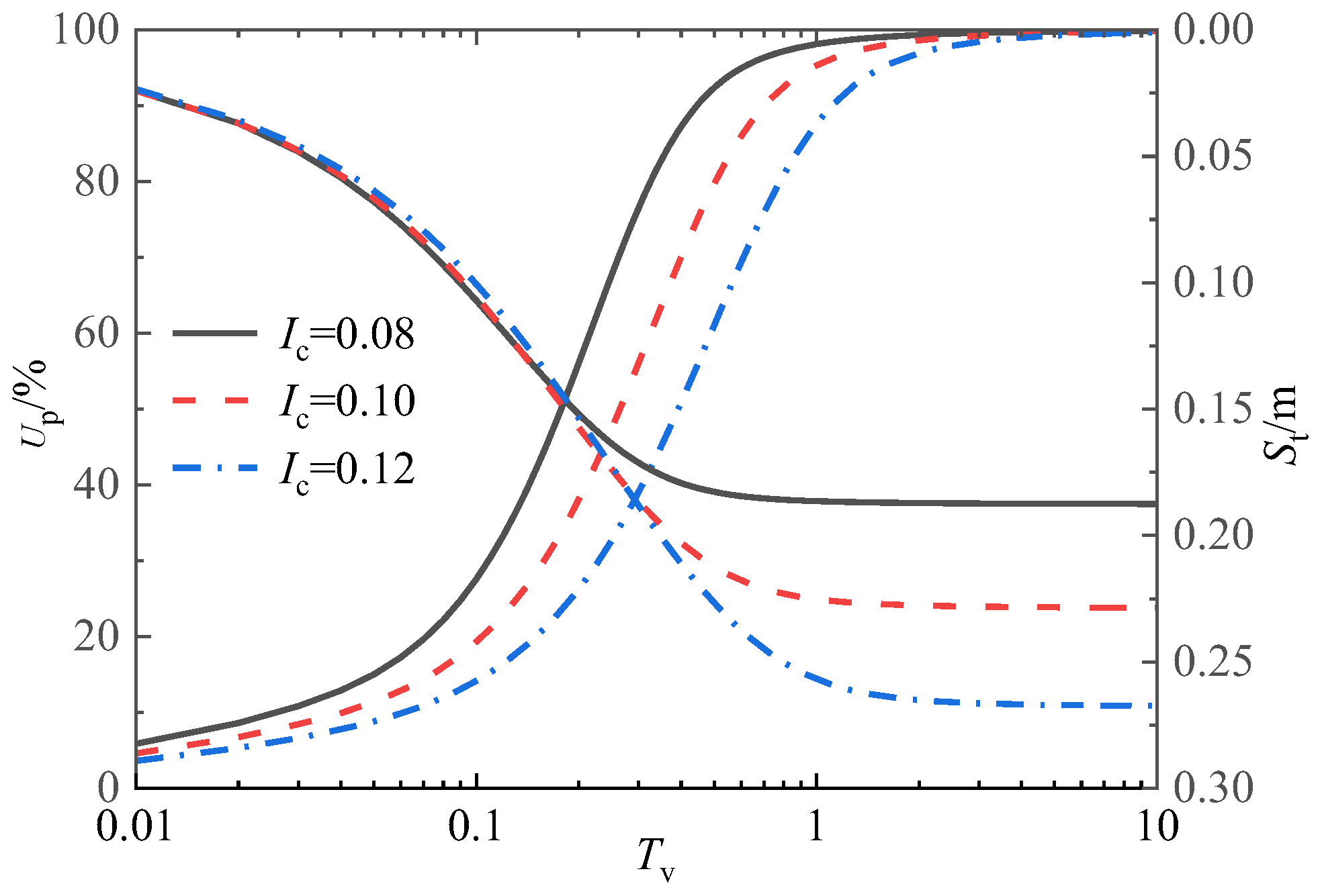
With the increase in the compression index and permeability index, the consolidation rate of sand-drained foundations slows down; the final settlement increases with the increase in the compression index, while the permeability index does not affect the final settlement.
(5)
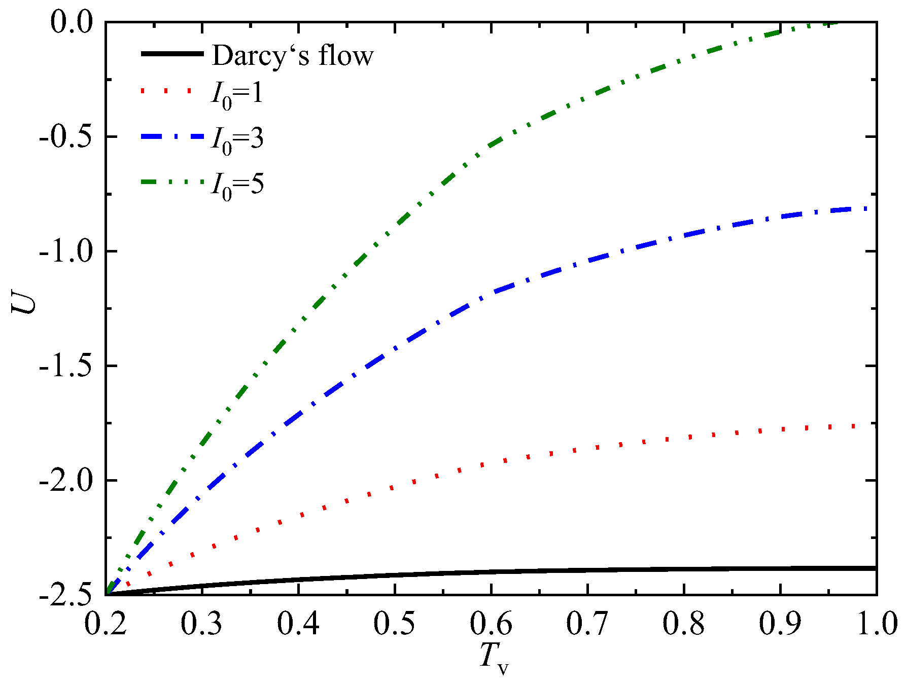
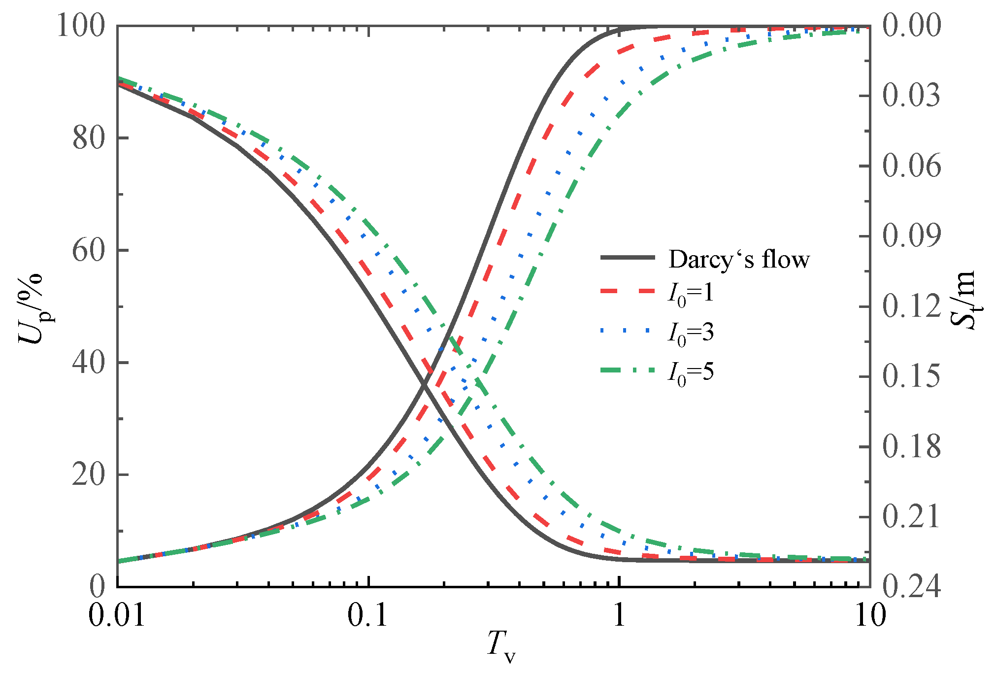
Considering the seepage parameter, I0, the consolidation rate of sand-drained foundations becomes slower, and the maximum deviation of the consolidation degree can reach 38.2%. Therefore, ignoring the non-Darcy flow effect will significantly overestimate the consolidation rate of the sand-drained foundations. Nevertheless, the seepage parameter I0 does not affect the final settlement, indicating that the prediction of the final settlement result can be captured using a concise Darcy’s law.
(6)
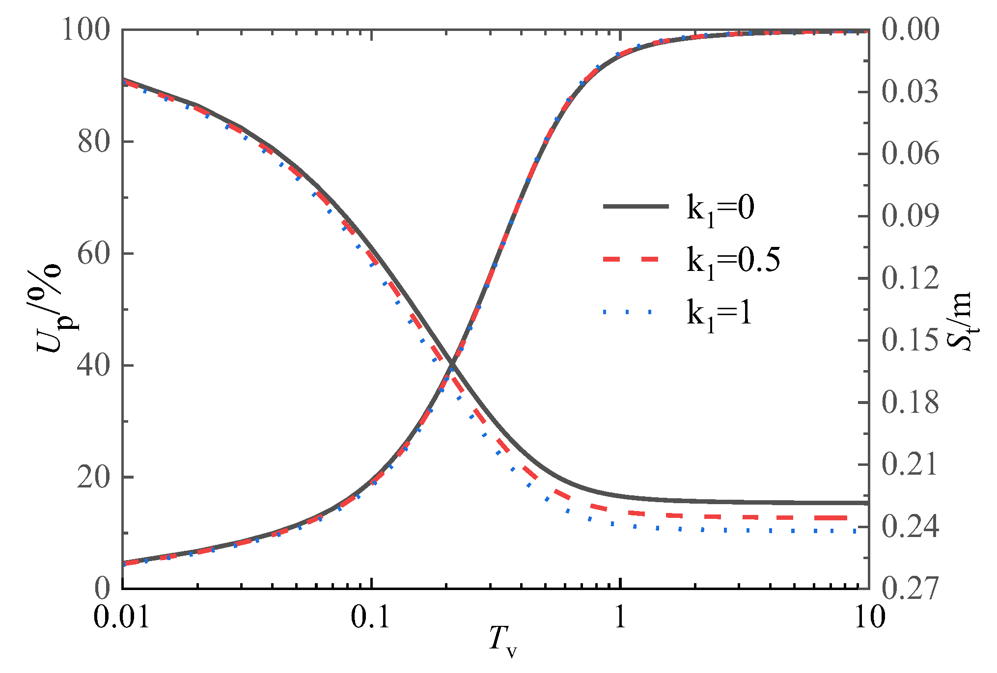
The negative pressure transfer coefficient k1 has little effect on the consolidation rate of sand-drain foundations, but a decrease in the negative pressure transfer coefficient, k1, will result in a decrease in both the settlement rate and the final settlement amount of sand-drained foundations.

Author Contributions

Review and editing, Validation, Z.X.; Conceptualization, Writing—original draft preparation, P.C.; Supervision W.C.; Writing—review and editing, X.Z. and J.Z.; Validation, Investigation, J.Z. All authors have read and agreed to the published version of the manuscript.

Funding

The authors declare that this study received funding from the National Nature Science Foundation of China (grant 51879104), and the Hunan Provincial Social Science Achievement Review Committee Subjects (grant 2023844). The support is gratefully acknowledged.

Data Availability Statement

The data that support the findings of this study are available from the corresponding author upon reasonable request.

Conflicts of Interest

Author Xingyi Zhang was employed by the company Power China Zhong Nan Engineering Corporation Limited. The remaining authors declare that the research was conducted in the absence of any commercial or financial relationships that could be construed as a potential conflict of interest.

References

  1. Basu, D.; Basu, P.; Prezzi, M. Analytical solutions for consolidation aided by vertical drains. Geomech. Geoeng. 2006, 1, 63–71. [Google Scholar] [CrossRef]
  2. Walker, R.; Inraratna, B. Vertical Drain Consolidation with Parabolic Distribution of Permeability in Smear Zone. J. Geotech. Geoenviron. Eng. 2006, 132, 937–941. [Google Scholar] [CrossRef]
  3. Davis, E.H.; Raymond, G.P. A non-Linear theory of consolidation. Géotechnique 1965, 15, 161–173. [Google Scholar] [CrossRef]
  4. Xie, K.H.; Leo, C.J. Analytical solutions of one-dimensional large strain consolidation of saturated and homogeneous clays. Comput. Geotech. 2004, 31, 301–314. [Google Scholar] [CrossRef]
  5. Hansbo, S. Consolidation of clay with special reference to influence of vertical sand drains. Swed. Geotech. Inst. Proceed. 1960, 18, 45–50. [Google Scholar]
  6. Swartzendruber, D. Modification of Darcy’s law for the flow of water in soils. Soil Sci. 1962, 93, 22–29. [Google Scholar] [CrossRef]
  7. Miller, R.J.; Low, P.E. Threshold gradient for water flow in clay systems. Soil Sci. Soc. Am. J. 1963, 27, 605–660. [Google Scholar] [CrossRef]
  8. Mohamedelhassan, E.; Shang, J.Q. Vacuum and surcharge combined one-dimensional consolidation of clay soils. Can. Geotech. J. 2002, 39, 1126. [Google Scholar] [CrossRef]
  9. Kianfar, K.; Indraratna, B.; Rujikiatkamjorn, C.; Leroueil, S. Radial consolidation response upon the application and removal of vacuum and fill loading. Can. Geotech. J. 2015, 52, 2156. [Google Scholar] [CrossRef]
  10. Chai, J.C.; Hong, Z.S.; Shen, S.L. Vacuum-drain consolidation induced pressure distribution and ground deformation. Geotext. Geomembr. 2010, 28, 525–535. [Google Scholar] [CrossRef]
  11. Indraratna, B.; Rujikiatkamjorn, C.; Sathananthan, L. Radial consolidation of clay using compressibility indices and varying horizontal permeability. Can. Geotech. J. 2005, 42, 1330–1341. [Google Scholar] [CrossRef]
  12. Geng, X.Y.; Indraratna, B.; Rujikiatkamjorn, C. Analytical Solutions for a Single Vertical Drain with Vacuum and Time-Dependent Surcharge Preloading in Membrane and Membraneless Systems. Int. J. Geomech. 2012, 12, 27–42. [Google Scholar] [CrossRef]
  13. Gibson, R.E.; England, G.L.; Hussey, M.J.L. The theory of one-dimensional consolidation of saturated clays. Part I: Finite nonlinear consolidation of thin homogeneous layers. Geotechnique 1967, 17, 261–273. [Google Scholar] [CrossRef]
  14. Fox, P.J.; Di Nicola, M.; Quigley, D.W. Piecewise-linear model for large strain radial consolidation. J. Geotech. Geoenviron. Eng. 2003, 129, 940–950. [Google Scholar] [CrossRef]
  15. McVay, M.; Townsend, F.C.; Bloomquist, D. One-dimensional Lagrangian consolidation. J. Geotech. Eng. 1989, 115, 893–898. [Google Scholar] [CrossRef]
  16. Perera, D.; Indraratna, B.; Leroueil, S.; Rujikiatkamjorn, C.; Kelly, R. Analytical model for vacuum consolidation incorporating soil disturbance caused by mandrel-driven drains. Can. Geotech. J. 2017, 54, 547–560. [Google Scholar] [CrossRef]
  17. Geng, X.Y.; Yu, H.S. A large-strain radial consolidation theory for soft clays improved by vertical drains. Géotechnique 2017, 67, 1020–1028. [Google Scholar] [CrossRef]
  18. Nguyen, B.P.; Kim, Y.T. Radial consolidation of PVD-Installed normally consolidated soil with discharge capacity reduction using large-strain theory. Geotext. Geomembr. 2019, 47, 243–254. [Google Scholar] [CrossRef]
  19. Walker, R.; Indraratna, B. Vertical drain consolidation with overlapping smear zones. Géotechnique 2007, 57, 463–467. [Google Scholar] [CrossRef]
  20. Butterfield, R. A natural compression law for soils(an advance on e-log p’). Geotechnique 1979, 29, 469–480. [Google Scholar] [CrossRef]
  21. Tavenas, F.; Jean, P.; Leblond, P.; Leroueil, S. The permeability of natural soft clays, Part II: Permeability characteristics. Can. Geotech. J. 1983, 20, 645–660. [Google Scholar] [CrossRef]
  22. Li, C.X.; Qiu, C. An analytical solution for one-dimensional nonlinear large-strain consolidation of soft clay with high compressibility. Chin. J. Rock Mech. Eng. 2021, 40, 2344–2356. (In Chinese) [Google Scholar] [CrossRef]
  23. Shafee, A.; Khoshghalb, A. Particle node-based smoothed point interpolation method with stress regularisation for large deformation problems in geomechanics. Comput. Geotech. 2022, 141, 104494. [Google Scholar] [CrossRef]
  24. Bui, H.H.; Nguyen, G.D. Smoothed particle hydrodynamics (SPH) and its applications in geomechanics: From solid fracture to granular behaviour and multiphase flows in porous media. Comput. Geotech. 2021, 138, 104315. [Google Scholar] [CrossRef]
  25. Wang, D.; Bienen, B.; Nazem, M.; Tian, Y.; Zheng, J.; Pucker, T.; Randolph, M.F. Large deformation finite element analyses in geotechnical engineering. Comput. Geotech. 2015, 65, 104–114. [Google Scholar] [CrossRef]
  26. Guo, N.; Yang, Z.; Yuan, W.; Zhao, J. A coupled SPFEM/DEM approach for multiscale modeling of large-deformation geomechanical problems. Int. J. Numer. Anal. Meth. Geomech. 2021, 45, 648–667. [Google Scholar] [CrossRef]
  27. Xu, Z.; Cao, W.; Cui, P.; Li, H.; Wei, Y. Analysis of One-Dimensional Consolidation Considering Non-Darcian Flow Described by Non-Newtonian Index incorporating Impeded Drainage Boundaries. Water 2022, 14, 1740. [Google Scholar] [CrossRef]
  28. Cui, P.; Cao, W.; Xu, Z.; Li, H.; Hu, M. One-dimensional nonlinear rheological consolidation analysis of soft ground under continuous drainage boundary conditions. Comput. Geotech. 2023, 156, 105283. [Google Scholar] [CrossRef]
  29. Barron, R.A. Consolidation of fine-grained soils by drain wells. Trans. Am. Soc. Civ. Eng. 1948, 74, 718–742. [Google Scholar] [CrossRef]
  30. Carrillo, N. Simple two and three dimensional cases in the theory of consolidation of soils. J. Math. Phys. 1942, 21, 1–5. [Google Scholar] [CrossRef]
  31. Xie, K.H.; Zeng, G.X. Analytical theory of sand well foundation consolidation under constant strain condition. Chin. J. Geotech. Eng. 1989, 11, 3–17. (In Chinese) [Google Scholar]
  32. Li, G.X. Advanced Soil Mechanics; Tsinghua University Press: Beijing, China, 2004; pp. 75–80. (In Chinese) [Google Scholar]
  33. Cui, P.; Cao, W.; Liu, Y.; Zhang, X.; Li, H.; Xu, Z. One-dimensional nonlinear creep consolidation of soft soils with time-dependent drainage boundary under construction load. Int. J. Numer. Anal. Methods Geomech. 2023, 47, 1612–1636. [Google Scholar] [CrossRef]
  34. Cui, P.; Cao, W.; Lin, C.; Liu, Y.; Chen, M.; Zhang, J. 1D elastic viscoplastic consolidation analysis of bi-layered soft ground under time-dependent drainage boundary and ramp load. Int. J. Numer. Anal. Methods Geomech. 2023, 1–23. [Google Scholar] [CrossRef]
  35. Cui, P.; Cao, W.; Xu, Z.; Wei, Y.; Li, H. Analysis of one-dimensional nonlinear rheological consolidation of saturated clay considering self-weight stress and Swartzendruber’s flow rule. Int. J. Numer. Anal. Methods Geomech. 2022, 46, 1205–1223. [Google Scholar] [CrossRef]
  36. Gu, M.; Zhao, M.; Zhang, L.; Han, J. Effects of geogrid encasement on lateral and vertical deformations of stone columns in model tests. Geosynth. Int. 2016, 23, 100–112. [Google Scholar] [CrossRef]
  37. Gu, M.; Han, J.; Zhao, M.H. Three-dimensional discrete element method analysis of stresses and deformations of single geogrid-encased stone column. Int. J. Geomech. ASCE 2017, 17, 04017070. [Google Scholar] [CrossRef]
  38. Gu, M.; Cai, X.; Mo, H.; Wang, Q. Unconfined compressive behavior of column with geogrid-encased recycled aggregate: Test and simulation. Constr. Build. Mater. 2023, 400, 132528. [Google Scholar] [CrossRef]
Figure 1. Calculation diagram.
Buildings 13 02843 g001
Figure 2. Overload load modes.
Buildings 13 02843 g002
Figure 3. The non-Newtonian index flow curve.
Buildings 13 02843 g003
Figure 4. Variation modes of radial permeability coefficient in the smear area.
Buildings 13 02843 g004
Figure 5. lg(1 + e) − lg σ′ compression curve.
Buildings 13 02843 g005
Figure 6. lg(1 + e) − lg kr permeation curve.
Buildings 13 02843 g006
Figure 7. Theoretical vs. experimental comparison in this paper.
Buildings 13 02843 g007
Figure 8. Verification with the analytical solution.
Buildings 13 02843 g008
Figure 9. Distribution of pore pressure in the middle soil layer with different loading modes (P0 = 5, Tv = 1).
Buildings 13 02843 g009
Figure 10. Distribution of pore pressure in intermediate soil layers with different loading modes (P0 = 20, Tv = 1).
Buildings 13 02843 g010
Figure 11. Distribution of pore pressure with three different radical permeability variation modes (P0 = 5, Tv = 1).
Buildings 13 02843 g011
Figure 12. Distribution of pore pressure with different compression index, Ic, values (Tv = 1).
Buildings 13 02843 g012
Figure 13. Distribution of pore pressure with different permeability index, α, values (Tv = 1).
Buildings 13 02843 g013
Figure 14. Distribution of pore pressure with different seepage parameter, I0, values (Tv = 1).
Buildings 13 02843 g014
Figure 15. Up and St under three variation modes of radical permeability coefficient at smear zone.
Buildings 13 02843 g015
Figure 16. Influence of vacuum preloading on Up under different loading modes.
Buildings 13 02843 g016
Figure 17. Up and St of different compression index Ic values.
Buildings 13 02843 g017
Figure 18. Up and St of different permeability index α values.
Buildings 13 02843 g018
Figure 19. UP curves with time Tv of different drain spacing ratios, n.
Buildings 13 02843 g019
Figure 20. Up and St under different dimensionless seepage parameters, I0.
Buildings 13 02843 g020
Figure 21. Up and St with time, Tv, curves under negative pressure transfer coefficient, k1.
Buildings 13 02843 g021
Table 1. The geotechnical parameters from indoor tests.
rw(m)re(m)rs(m)kr0(m/s)δσ0′(kPa)e0qu(kPa)
0.0330.2250.14.6 × 10−102/320130
Disclaimer/Publisher’s Note: The statements, opinions and data contained in all publications are solely those of the individual author(s) and contributor(s) and not of MDPI and/or the editor(s). MDPI and/or the editor(s) disclaim responsibility for any injury to people or property resulting from any ideas, methods, instructions or products referred to in the content.

