Abstract
This investigation aimed to comprehensively investigate the integrity and failure characteristics of deteriorated polymeric components produced through Fused Filament Fabrication (FFF) technology. The primary focus was to examine the performance of flawed 3D-printed samples, which were purposely designed and 3D-printed to incorporate a range of crack types and geometric features that were initially designed through CAD. This study adopted two main approaches to deal with the cracks by producing the flaws through design and laser processes. These specimens were subjected to destructive testing to gain valuable insights into the FFF-printed components’ performance and failure characteristics under the tensile mode, a significant concern in engineering applications. A Finite Element Analysis (FEA) was employed on the flawed and intact specimens to compare and correlate the experimental results with the simulation results. This study reveals the tested samples’ structural response and failure mechanisms under tensile loading conditions. Exceptionally, it was found that the faulty 3D-printed parts made by the laser process demonstrated less resistance to failure due to disturbing the 3D-printed extruded filament streams. In contrast, the flaws initially produced solely by the 3D printing process showed better resistance to mechanical failure due to the crack-bridging effect. It was observed that there were reductions of 11% and 32% in the failure load of the 3D-printed cracked sample and the laser-cracked samples, respectively, in comparison with the intact one. Additionally, the stress intensity factor showed a decrease of 20% in the laser-cracked sample compared to the 3D-printed one.
1. Introduction
In the past few decades, there has been significant growth and advancement in additive manufacturing (AM) technology. These significant advancements are leading to the widespread adoption of this technology and its corresponding application in various industries, such as manufacturing, construction, and education [1]. The adaptability and benefits offered by AM have boosted its growth, enabling the production of complex components and structures through 3D printing. Nowadays, a wide range of materials [2], including polymers, metals, non-metals, biomasses, and ceramics, are utilized for additive manufacturing [3]. Additionally, various AM technologies have emerged to facilitate the process of 3D printing, each with its own unique features and applications [4]. This continuous expansion of material options and AM technologies has opened new possibilities for innovation and creativity in manufacturing and other fields. Through particular analysis and experimentation, researchers delve into the intricate relationship between AM processes and the resulting mechanical properties of the components. By thoroughly understanding the failure mechanisms, they attempt to develop strategies to mitigate and eliminate the adverse effects caused by inherent flaws and stress concentration, ultimately enhancing the overall performance and reliability of AM-produced parts [5]. Such investigations investigate aspects like the influence of different printing parameters, material characteristics, and post-processing techniques on mechanical properties and failure behavior. By shedding light on these critical factors, researchers pave the way for optimized design guidelines, process improvements, and quality control measures that can ensure the production of durable and high-performance components using AM technology. The collective efforts of these researchers contribute to the ever-growing body of knowledge surrounding AM technology, fostering its continuous improvement and expanding its potential applications in diverse industries. Additive manufacturing (AM), or 3D printing, utilizes different techniques to construct objects layer by layer based on digital designs. Although AM presents numerous advantages, it also confronts challenges, such as the potential for failure. Several AM techniques, such as fused deposition modeling (OFDM), entail extruding molten thermoplastic material through a nozzle to build layers. However, this approach faces various challenges. One notable issue is the subpar surface finish, as FDM parts often exhibit visible layer lines, which can adversely impact the printed objects’ aesthetics and functionality [6]. Additionally, weak interlayer bonding is a concern, as delamination or insufficient adhesion between layers can reduce mechanical strength. Another challenge is warping and distortion, particularly in large, flat parts, as differential cooling rates can cause warping or distortion, affecting the printed components’ dimensional accuracy. Stereolithography (SLA) is a technique that utilizes a UV laser to solidify liquid photopolymer resin in a layer-by-layer fashion. However, this method faces a significant challenge: the resulting parts tend to be brittle, primarily due to the inherent characteristics of the cured resin [7]. Consequently, their utility is limited in applications where impact resistance is crucial. Furthermore, the support structures used to prevent the collapse of intricate parts during the printing process pose another challenge. Their removal can be a time-consuming and arduous task. Moreover, SLA is constrained by a limited material selection, often confined to specific resin materials, which restricts the range of available properties that can be achieved through this technique. Selective laser sintering (SLS) is a technique that utilizes a high-power laser to fuse powdered materials, commonly polymers or metals, selectively. However, this process faces several challenges. First, managing and recycling unused powder while maintaining consistent powder quality can be complex [8]. Additionally, the rapid heating and cooling during the laser sintering process can generate thermal stresses, potentially resulting in part distortion or cracking. Another challenge arises from the need for support structures, which are often necessary during printing and must be subsequently removed, thereby adding additional post-processing steps to the workflow. Electron Beam Melting (EBM) is a technique that employs an electron beam to melt and fuse metallic powders layer by layer within a vacuum environment. However, this approach encounters several challenges. Firstly, the high process temperatures can result in residual stresses and thermal distortion, impacting the overall quality of the printed parts [9]. Moreover, the selection of materials for EBM is comparatively limited compared to other additive manufacturing techniques, which restricts the available options for various applications. Additionally, the complex equipment requirements for EBM are costly and necessitate specialized expertise to operate and maintain them effectively. Common challenges exist across various AM techniques, starting with design constraints. AM often imposes specific design requirements, such as minimizing overhangs or incorporating supporting structures, which can restrict design freedom and innovation. Moreover, material inconsistencies pose a significant challenge. The quality and consistency of materials used in AM can vary, directly impacting the integrity and reliability of the printed parts [10]. Additionally, process optimization plays a crucial role. Fine tuning AM parameters, such as layer thickness, print speed, or heat distribution, is vital for achieving the desired part quality and preventing failures. Another obstacle lies in post-processing and finishing. Printed parts often necessitate additional steps, such as support removal, sanding, or polishing, introducing risks of damage or inaccuracies during these stages. Quality control and inspection present another challenge. Developing robust quality control methods for AM parts, including non-destructive testing, can be particularly demanding due to AM processes’ complex geometries and internal structures.
Concrete 3D printing has revolutionized construction by using digital models to construct structures layer by layer, reducing the need for formwork [11]. It offers benefits such as improved productivity, enhanced quality, and the ability to create complex components [12]. This method enables the creation of customized structures at a lower cost and in less time [13]. It also reduces material waste and environmental impact through efficient material use and optimized designs [14]. Researchers have investigated various aspects of concrete additive manufacturing, including its potential, challenges, and barriers [15]. This includes assessing its feasibility, comparing AM methods, advancing printing systems, exploring reinforcement strategies, optimizing digital planning processes, evaluating applications, and analyzing market impacts. These efforts contribute to the integration of concrete AM into the industry, fostering efficiency and sustainability in construction practices [16]. A contemporary assessment of production methodologies for primary load-bearing 3D-printed elements has been discussed [17], encompassing walls, columns, slabs, and beams, with the aim of recognizing prevailing patterns and persistent obstacles.
A technique was formulated by Shafighfard et al. [18] for the production of 3D-printed composite materials incorporating short fibers, focusing on enhancing fiber alignment or printing orientations. The conventional open-hole tension specimen configuration was chosen as the experimental model. The approach of employing the least squares method along with continuity constraints was adopted to design the varying local fiber orientations within each layer, all aimed at achieving the best possible compliance reduction. Additionally, an algorithm was devised to transform the optimal discrete fiber. A previous study aimed to enhance safety standards, particularly emphasizing fracture mechanics principles [19]. Fracture mechanics examines material deterioration and the breakdown caused by internal imperfections and fissures [20]. By applying fracture mechanics principles, researchers sought to determine the stress levels at which cracks of known spatial arrangements and physical shapes can move within a material, ultimately triggering collapse [21]. This analysis applies to structures ranging from the macro-scale to the micro-scale. It is conducted analytically and through advanced computational techniques like the finite element method. Through these investigations, researchers sought to thoroughly comprehend the characteristics and actions of materials and components subjected to varying loads and environmental conditions [22]. By studying the propagation of cracks and their influence on the overall structural integrity, they aimed to develop strategies to mitigate or prevent catastrophic failures. This information is crucial for designing robust components and systems that withstand anticipated stress levels and operational conditions. The analytical approaches employed in these studies involved mathematical models, equations, and theoretical analyses to predict the behavior of cracks and to evaluate the structural response [23]. Additionally, computational techniques, like the finite element method, are utilized to solve complex problems numerically and are utilized to simulate and analyze complex systems with intricate crack geometries. Researchers have combined experimental data, theoretical models, and numerical simulations to establish a comprehensive understanding of how cracks propagate and interact within materials. This knowledge contributes to developing design guidelines, material selection criteria, and structural optimization strategies, ultimately enhancing the durability and safety levels of components produced through AM technology [24]. In another noteworthy study conducted by Ishii et al. [25], the fracture performance of a notched specimen fabricated via additive manufacturing was comprehensively investigated, focusing on different failure modes. The experimental analysis involved the utilization of polymeric specimens created using the fused deposition modeling method, a popular 3D printing technology. This investigation aimed to gain insights into the fracture performance exhibited by 3D-printed parts according to bending testing standards. Through carefully designed experiments, Xu et al. [26] examined the fracture behavior of 3D-printed components, specifically considering the influence of different curvatures. By subjecting the specimens to flexural loading, the study aimed to establish a fracture criterion that would effectively describe the materials’ behavior, taking into account both tensile and compressive stresses. The investigation encompassed a comprehensive evaluation of the fracture mechanics associated with the 3D-printed components, focusing on understanding the materials’ response to different loading conditions and geometric configurations. This enabled the researchers to characterize the fracture behavior and identify critical factors that influenced the structural integrity and failure mechanisms of the 3D-printed components. Developing a fracture criterion based on the experimental results and analysis provided valuable insights into the materials’ functioning and failure modes. By considering both tensile and compressive stresses, the criterion offered a comprehensive framework to understand the fracture manners exhibited by the printed components according to flexural testing standards. This knowledge is crucial for designing robust components, optimizing the 3D printing process, and ensuring the reliability and safety of structures produced using AM technology. The combination of experimental testing, analysis, and establishing a fracture criterion contributed to the growing body of knowledge surrounding the fracture behavior of 3D-printed components, facilitating advancements in design methodologies and material selection strategies for additive manufacturing applications. An investigation was conducted to analyze the deformation and fracture behavior in a 3D-printed model, specifically concerning a disordered lattice material under the application of uniaxial tensile stress. To accurately predict the behavior of crack patterns and the load concerning the displacement relationship in these 3D-printed lattice parts, a sophisticated lattice pattern was devised by researchers [27]. The lattice model was designed to investigate the impact of the used structures commonly observed in printed components, with a particular emphasis on examining two-directional 3D-printed components. By employing this lattice model, the study aimed to gain comprehensive insights into the fracture characteristics and deformation of the printed lattice material, contributing to a deeper understanding of the mechanical behavior and failure mechanisms inherent in such structures. Another research study revealed the prominence of filament-scale geometric features in the fracture behavior of specifically fabricated, printed, and optimized tension specimens compared to filament bonding. These specimens were regularly analyzed along the direction of the extrusion, whereas it was observed that the filament direction exhibited higher toughness and strength [28]. Additionally, a current condition according to material-induced stress was proposed by Aliheidari et al. [29], where the orientation of the filaments aligned with the principal stress directions within the tested samples. To explore the fracture behavior of cracked specimens, several samples were printed, considering both new criteria. Noori et al. [30] focused on evaluating the fracture resistance and the adhesion between layers of printed materials produced through Fused Filament Fabrication (FFF). They employed double-cantilever-beam specimens made of acrylonitrile butadiene styrene to characterize these properties. The developed samples were deliberately designed and produced with the existence of an induced crack positioned at the edge between the layers, specifically in the opening mode. This design allowed for the determination of the critical load required to initiate the crack. The research conducted by Zolfagharian et al. [31] aimed to explore the influence of deposition height on the fracture behavior of printed polylactic acid (PLA) samples under axial load. The results revealed a notable finding: the interlayer fracture requires energy, which is closely related to deposition thickness. By examining fracture behavior, the study shed light on the impact of the parameters of the deposition and the mechanical characteristics of the PLA-printed materials. In a related effort, Cuesta et al. [32] explored the modes of fractured 3D-printed components made of three different polymers—Onyx, acrystalline, and nylon-reinforced polymers—and three standard polymers used in additive manufacturing—PLA, PP, and ABS—using numerous additive manufacturing technologies. The study employed experimental and numerical approaches to analyze fracture behavior. Specifically, it focused on determining the stress capability to afford an applied load of a 3D-printed cracked sheet. The investigation utilized the hypothesis of equivalent material and employed a failure criterion of the J-integral to assess the cracked specimens’ failure. This comprehensive analysis provided precise details on the fracture resistance of polymers produced using 3D printing technology and highlighted the factors affecting their structural integrity. In another study conducted by Gendviliene et al. [33], the behavior of plates produced using FFF polymeric 3D printing was investigated. The objective of the research was to investigate how adding fiber reinforcement affects the ability of polymer sheets created through additive manufacturing to withstand fractures.
However, the fracture behavior of 3D-printed lattice materials has been the subject of significant research interest. Lattice structures are an essential component of additive manufacturing since there are numerous advantages over traditional solid structures, such as reduced material usage, increased design flexibility, and improved mechanical properties. A method was proposed to model the deformation and fracture behavior of 3D-printed disordered lattice materials under uniaxial tensile load [34]. The lattice model considers two types of printed elements, horizontally and vertically printed, to simulate typical layered structures of 3D-printed materials. By comparing simulations and experimental tests, it was found that assigning measured strengths to elements with the same printing direction leads to accurate predictions of crack patterns and load–displacement curves, highlighting the significance of considering the printing direction in simulating the mechanical performance of 3D-printed structures. Li et al. [35] showed that surface roughness significantly affects the fracture behavior of 3D-printed lattice structures (DOD and BCC). Tensile tests on flat specimens with varying roughness showed their importance in fracture elongation. FEM simulations, incorporating strut diameter variations and a damage model, matched the experimental results, confirming surface roughness as a critical factor influencing lattice strength and fracture behavior. Nano-architected lattices are a new class of metamaterials with exceptional mechanical properties. However, understanding their fracture characteristics is crucial for engineering applications. In Maurizi et al.’s investigation [36], in situ tensile fracture experiments and finite element simulations revealed the potential for stable crack growth using intrinsic plastic toughening.
Moreover, the fracture properties of octet and 3D kagome architectures show similar performance in one direction. Stochastic lattice structures are modeled using a generative algorithm based on Voronoi tessellation, allowing for irregular cell geometry and variable strut sections [37]. The geometry is 3D-printed using a high-accuracy SLA 3D printer, and the mechanical properties are determined through tension experiments. Compressive tests on the printed structures align well with finite element simulations, offering valuable insights into their mechanical behavior and characterization. Advancements in additive manufacturing (AM) have led to the fabrication of parts with unique properties, especially porous lattice designs. However, evaluating numerous combinations of base materials and lattice designs is impractical. Peloquin et al. [38] proposed a framework using machine learning to predict vital mechanical properties of 3D-printed gyroid lattices based on the base material and porosity, offering accurate results in a fraction of the computation time compared to numerical simulations. The model provides a valuable tool for guiding future lattice design and material selection. Hamano et al. [39] studied the mechanical properties of binder jetting 3D-printed products using a crystal lattice model based on crystallographic logic. It was found that the print head’s nozzle pattern influenced the printed moldings’ mechanical anisotropy and fracture mode. The study offers new insights into understanding the anisotropic behavior of binder jetting 3D-printed products, providing valuable information for various industrial applications. Ameri et al. [40] evaluated the capability of fracture criteria and numerical methods to predict the fracture properties of specimens fabricated using Fused Deposition Modeling. Different thermoplastic materials were 3D-printed in a semi-circular bending specimen configuration and subjected to three-point bending loading to investigate their failure behavior, including final load-bearing and crack path trajectory. The effects of various printing parameters, including nozzle temperature, platform temperature, printing speed, and layer thickness, on the mechanical properties were studied by Wang et al. [41] to analyze the microstructure effects of FDM-3D printing parameters on mechanical properties. In a study by Naveed [42], two 3D printing material types—polylactic acid and tough PLA— were used to investigate the material properties of each 3D part and were analyzed to identify the best combination of the raster angle. A microstructural analysis was also performed on the outer and inner surfaces along with the fracture interface of the parts after tensile testing using scanning electron microscopy (SEM) to explain the material’s failure modes and reasons. Xu et al. [43] proposed a combined experimental and numerical investigation of a new interlayer shear strength measurement approach, and it targeted the applications of identical polyamide specimens made with fused deposition modeling and selective laser sintering. Saleh et al. [44] considered three triply periodic minimum surface (TPMS)-based lattice structure cell topologies, including diamond, gyroid, and primitive. The FDM process was used to print the lattice structures with two materials: pure polylactic acid and carbon-fiber-reinforced PLA. The influence of carbon fiber incorporation, unit cell type and size, and relative density on mechanical properties and failure patterns was explored comprehensively under uniaxial compression testing. Danilo [45] used infrared thermography to monitor the temperature evolution during static tensile tests and to assess the stress level that can initiate damage within materials, and a failure analysis was performed to correlate the mechanical behavior with the microstructural characteristics of the materials.
Unfortunately, all former studies that investigated defective or cracked 3D-printed components, designed and made the flaws or the defects as a pre-existing weakness in the 3D-printed parts, and this does not reflect the actual situation during service. The current research investigated how a manufacturing process involving 3D printing, primarily FFF technology, affects the mechanical characteristics of printed components, particularly those with intentional cracks that could exist after production but are not produced during the printing process, so we proposed a laser process to make post-process cracks instead of pre-process cracks in 3D-printed parts. Additionally, this study employed the application of Linear Elastic Fracture Mechanics to evaluate the failure characteristics demonstrated by the printed parts. This investigation uncovered a significant and noteworthy finding, shedding light on the crucial factors contributing to 3D-printed components’ failures due to different crack production processes supported by FEA. This research aimed to explore the influence of specific crack geometries on the characteristics of printed components, specifically in terms of tensile mode. The investigation revealed that cracks induced through the laser procedure exhibited a more critical predisposition towards failure when contrasted with damage originating from 3D printing. This underscores the significance of a thorough approach when selecting the appropriate methodology for assessing flawed components produced via 3D printing. Furthermore, it came to light that using laser processes for hole fabrication could compromise the structural integrity of 3D-printed components.
2. Material Characteristics
The 3D-printed specimens were created using the Ultimaker S5 3D printer model for investigating specific crack configurations (e.g., a through-thickness crack configuration) to gain insights into how these aspects affect the overall mechanical behavior of the produced parts. The considered specimens were fabricated using standard PLA filament material from Ultimaker (Utrecht, The Netherlands). Detailed information regarding the mechanical and material properties of the commercial filament adopted in this study can be found in Table 1, which provides comprehensive characteristics.

Table 1.
The mechanical properties of polylactic acid polymer [46].
Additionally, this study investigated different 3D Printed samples to comprehensively evaluate their mechanical behavior and potential failure mechanisms. Mainly, the samples underwent testing in the tensile mode. Tensile tests are commonly employed to assess a material’s response to an applied pulling force. The samples were tested under tensile loads to analyze their ability to withstand and distribute stress along the axial direction. This type of testing provides information on a sample’s tensile strength and stiffness, which are crucial in applications where materials experience bending loads or structural integrity is of concern. Figure 1 shows a 3D-printed sample under tensile test conditions.
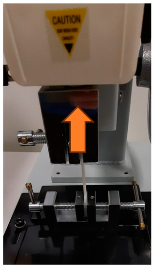
Figure 1.
A 3D-printed dog-bone sample under tensile test.
By conducting tests, this study aimed to thoroughly understand the mechanical behavior exhibited by the samples. This approach enabled a more thorough assessment of the samples’ responses to different manufacturing and loading conditions, providing valuable insights into their overall structural behavior and failure mechanisms. We utilized the tensile test sample configurations outlined in the ASTM D638 standard [47] on the intact and cracked samples. These sample configurations and their respective dimensions are visually depicted in Figure 2. By adhering to the testing standards, we ensured consistency and standardization in the testing methodology, enabling accurate comparisons between the intact and cracked samples’ tensile properties. It was observed that the actual 3D-printed elliptical crack was relatively smaller than the designed dimensions due to the capability of the FFF printer and the specifications of the extrusion nozzle used, such as the layer height, nozzle size, and extrusion width, as shown in Figure 3. In fact, FFF parts can experience some degree of shrinkage during the cooling process. This shrinkage may have caused the crack to appear smaller than the original design. On the contrary, the dimensions of the crack made by laser were identical to the design since the laser was able to precisely replicate the intended crack pattern, which is one of the factors that contributed to the laser-cracked sample failing earlier than the 3D-printed one, since the laser compromised the structural integrity of the material, making it more susceptible to failure under stress or load. Additionally, the process of creating the crack through laser could have introduced localized heat, residual stress, or other material defects that weakened the sample. These factors could have contributed to the premature failure of the laser-cracked sample.
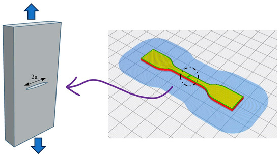
Figure 2.
A 3D-printed cracked dog-bone sample with elliptical crack.
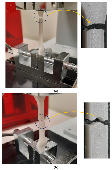
Figure 3.
Failure type and location for the different samples under tensile test. (a) Crack-free sample failure at the shoulder, (b) cracked sample failure at the center.
The tensile test samples were designed to include a specific through-thickness crack configuration. The adopted crack configuration featured a length of 0.1 cm, and the shape of the considered crack was elliptical, with a ratio of one to half between its major and minor axes, which means that the crack width was half the length, resulting in an elongated elliptical shape. Utilizing this specific crack geometry, we evaluated the mechanical response and behavior of the samples under tensile loading conditions. This configuration allows for a focused examination of the crack influence on a sample’s tensile properties. It provides valuable insights into the performance of 3D-printed components when subjected to tensile forces. It was observed that there were differences in failure behavior between the cracked and crack-free samples, particularly in terms of the failure location, as detailed below.
Cracked samples: The failure occurred at the midsection of the dog-bone sample, precisely at the crack location. This implies that the crack itself acted as a stress concentrator, causing a local increase in stress. As a result, the material failed at that specific point, with the crack propagating and leading to the ultimate failure of the sample.
Crack-free samples: In the absence of a crack, the failure location shifted to the shoulder radius of the sample. This region typically experiences a higher stress concentration due to the change in section dimensions. Stress concentration occurs when there is a sudden change in geometry, such as a reduction in the cross-sectional area or an abrupt change in curvature. In this case, the shoulder radius exhibited a higher stress level, eventually exceeding the material’s strength, resulting in failure at that location.
The observations that we provided highlight the significance of cracks as stress concentrators and the role of section dimensions in influencing failure locations in the tested samples for the cracked and crack-free samples, as demonstrated in Figure 3.
This research paid close attention to the printing parameters to ensure the consistent and reliable production of all samples, thereby maintaining the quality of the printed specimens. Table 2 details the typical printing parameters employed for the flawed and unflawed specimens, and these are used commercially for polymeric 3D-printed parts that have been optimized and tested intensively by many researchers as a reference setting, so no changes were made to the manufacturer parameters. Carefully, we adhered to these parameters to minimize variations in the printing process and guarantee a consistent sample quality across all experimental conditions. These parameters comprise various aspects, such as layer thickness, infill density, print speed, and temperature, which collectively contribute to the overall integrity and reliability of the printed samples.
Table 2.
Typical UM S5 3D Printing Settings.
To investigate how the process of making cracks in the 3D-printed specimens influences the failure and overall performance of the flawed 3D-printed specimens, a systematic examination was conducted, where three distinct sets of 3D-printed samples were examined. The crack initiation procedure, which was a critical aspect of the investigation, was carefully controlled and manipulated to analyze its impact on the samples’ integrity. For the 3D printing process, open-source slicing software named Cura 4.6 was utilized. This software works by taking the produced designed CAD model and slicing it into multi-layers stacked over each other and then creating a G code file that serves as instructions for the 3D printer during the fabrication of the physical parts. Using Cura in this study ensured a standardized and reliable approach to slicing the CAD models, as depicted in Figure 4, as well as enhancing the reproducibility and accuracy of the specimens under consideration. Figure 5 illustrates the actual 3D-printed samples, and the crack-free and cracked ones.
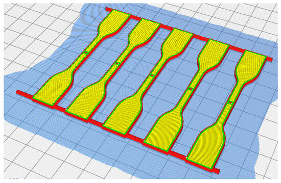
Figure 4.
Ultimaker S5 was employed in the printing process to manufacture tensile samples.
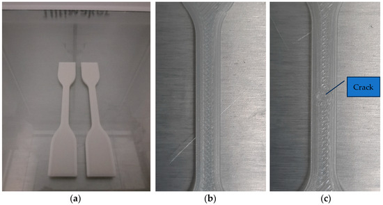
Figure 5.
(a) The 3D-printed samples, (b) crack-free sample, and (c) cracked sample.
Creating tiny holes in FFF (Fused Filament Fabrication) 3D printing can be challenging and may not be reliably achievable. The limitations of FFF technology, such as the nozzle diameter and layer height, make it tough to produce extremely small features, including holes and designed cracks [48]. Additionally, even with a small nozzle, the resolution is limited by factors like the filament flow rate, material properties, and the overall mechanical technology of the printer. Moreover, the layer height also affects the precision of small features [49]. Smaller layer heights improve the vertical resolution but can significantly increase the print time, and minimal layer heights may result in poor adhesion between layers. Additionally, the material properties play a role in the ability to create small holes. Some materials used in FFF 3D printing, such as thermoplastics, may have limitations in their flow and viscosity, making it challenging to achieve outstanding details [50]. Accordingly, this study was limited to the elliptical through-thickness crack dimensions of 1 mm to 0.5 mm, which were the only dimensions that could be printed, with ratios of 1 to 0.3 and 1 to 0.1 being excluded from the experimental investigation due to the FFF printing constraints of the used 3D printer; trials were conducted to produce the designed geometries of the crack, but they were unsuccessful.
In this particular study, the 3D-printed samples were fabricated with 100% density, employing a linear infill pattern to create solid specimens. The choice of infill pattern and density was intentionally kept consistent, as the primary objective of the study did not revolve around investigating the influence of various infill patterns or densities on failure performance. Instead, the focus was on examining the significance of disparities between pre-cracked and post-crack samples and assessing the potential impact on the overall integrity of the specimens.
The samples experienced slow-speed testing (i.e., 1 mm/min) using a uniaxial tensile testing rig. Distinct identification methods were employed to differentiate the samples based on their manufacturing process. The samples were categorized as follows:
- The 3D-printed intact samples: These samples were produced without any cracks, and they served as the baseline for comparison against the other sample types.
- The 3D-printed flawed samples: For this category, a central through-thickness crack with an aspect ratio of one to half was introduced into all samples using 3D printing technology. This specific crack geometry was consistently applied across these samples.
- The 3D-printed flawed samples produced by laser: In this case, a commercial, multi-purpose machine for acrylic laser cutting was utilized to create elliptical cracks in the unflawed specimens. The laser cutting method was employed to generate the desired crack configuration, which differed from the 3D printing technology used for the printed hole samples, as shown in Figure 6.
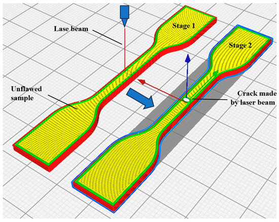 Figure 6. Steps to produce flawed sample by laser process using unflawed 3D-printed sample.
This study ensured a clear differentiation between the samples based on the manufacturing processes employed by utilizing these distinct identification methods. This allowed for a comprehensive examination of the impacts of numerous crack initiation techniques attributed to the failure characteristics of the specimens produced using FFF.
In general, many factors can affect the quality of 3D-printed parts. Ouassil et al. [51] examined the impact of various factors on the mechanical properties of 3D-printed polyetherimide (PEI) parts in the Z-direction. The research highlighted that the Fused Filament Fabrication process has limitations in achieving desirable mechanical properties in this direction. The study found that adjustment to the printing speed is the most crucial parameter. At the same time, the specimen’s state (annealed or as-printed) had a negligible influence due to the amorphous nature of PEI. Moreover, another study [52] examined the impact of process variables and strain rate sensitivity on the mechanical characteristics of Onyx, a composite material made of nylon and carbon fiber, fabricated using Fused Filament Fabrication (FFF). The study revealed that variations in printing parameters, such as platform temperature and print speed, significantly affected the tensile behavior of the 3D-printed specimens. Higher platform temperatures increased Young’s modulus and tensile strength but decreased failure strain, while increased print speeds enhanced tensile strength but decreased failure strain. Additionally, the strain rate notably influenced the failure mechanism, transitioning from ductile to brittle behavior as the elongation speed increased.
3. Results and Discussion
The five printed samples were tested under tensile test mode, but only the best three results were considered in the statistical analysis. Figure 7 illustrates the tensile test behavior of the three different specimens examined in this study, highlighting the distinct characteristics observed during the testing process. Notably, the results exhibit a discernible reduction in tensile stress for both cracked samples, signifying their diminished structural integrity. Additionally, a considerable decrease in elongation at break is evident, indicating the reduced capacity of the specimens to withstand deformation before fracture. These findings underscore the importance of understanding the effects of cracks on the mechanical properties of the materials under investigation. The data presented in Figure 7 serve as crucial evidence in comprehending the behavior of the tested specimens and can contribute significantly to further research and engineering applications.
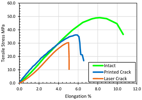
Figure 7.
Stress–strain curves of a sample of three tested specimens.
The summarized results are depicted in Figure 8, which shows the normalized max load at failure, where the FEA is considered as the reference load for the analysis. The results revealed that the unflawed samples experienced failure at a 0.42 kN applied load and at an 8.5 standard deviation. However, the printed cracked samples displayed a decrease of 4.8% in the failure load. Statistically, the standard deviations were 8.27, 6.95, and 5.20 for the intact, 3D-printed crack, and laser-cracked samples, respectively. However, the estimated coefficient of variations (CVs) for the intact, 3D-printed crack, and laser-cracked samples were 0.0198, 0.0175, and 0.0170, respectively.
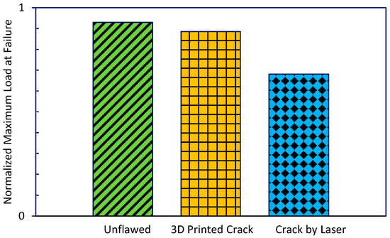
Figure 8.
Normalized highest load observed at the moment of failure in the 3D-printed specimens.
The microscopic images illustrate the differences between the failure of the intact samples and the flawed one, as shown in Figure 9.
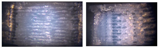
Figure 9.
Microscopic image of the intact failure (left) and the flawed failure (right).
This observation highlights the beneficial influence of the filament contours made during the slicing process of the generated model, as depicted in Figure 10. The stream flow of the stress is facilitated by the extruded contours around the elliptical crack, which plays a significant role in explaining the reduced substantial stress concentration around the crack and, hence, the load level of the failure. The contours produced during the extrusion process contribute to the redistribution and dissipation of stress around the crack profile. Cracks in 3D-printed parts can have a detrimental effect on their tensile strength, which could occur through incomplete fusion between layers or inadequate bonding [53]. These weak points along the crack can result in a loss of cohesive strength within the material, reducing its ability to resist the applied tensile forces. The crack can propagate more easily along the weak bonding lines, further compromising the tensile strength of the part. Additionally, as cracks propagate through a 3D-printed part under tensile loading, they act as fracture initiation points. The cracks can grow and link together, ultimately leading to catastrophic failure of the part [54]. This reduces the load-bearing capacity and ultimate tensile strength of the component, as the cracks significantly weaken the structural integrity of the material.
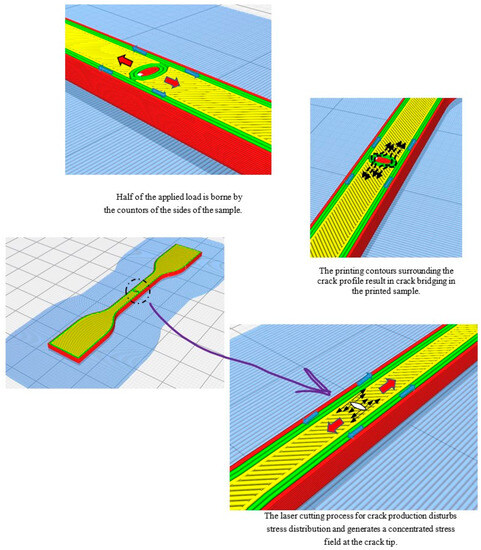
Figure 10.
A graphical representation demonstrating the stress flow distribution within the three samples.
Consequently, the 3D-printed contours surrounding the crack act as crack bridging effectively mitigating the typical stress concentration associated with cracks [55,56]. This phenomenon contributes to an enhanced load-bearing capacity and improved resistance to failure in printed parts. This observation became evident when comparing the failure load of the printed crack with that of the laser-cracked sample, as the former tended to exhibit higher strength. The slicing process employed in 3D printing plays a vital role in generating intricate extruded contours and optimizing stress distribution throughout the printed components. This optimization process ultimately reinforces the overall strength of the printed parts and provides valuable insights for applications where crack initiation and propagation are critical concerns. Hence, this crucial conclusion highlights a concern regarding the utilization of printed cracks in experimental research aimed at studying the performance of pre-cracked 3D-printed parts. Such an approach may fail to accurately reflect the actual behavior of the tested samples due to the presence of positive contours surrounding the crack. These contours have the potential to alleviate stress concentration, thereby leading to an increase in the failure load. To obtain a more authentic representation of the performance of deteriorated 3D-printed parts, it is recommended to introduce the crack through a post-processing method, such as machining or laser cutting. By employing these techniques, the crack can be precisely and controllably created without the additional positive contours that might influence stress concentration. Consequently, this approach would yield more reliable and precise results, enabling a comprehensive evaluation of the impact of cracks on the structural integrity and failure behavior of 3D-printed components.
Furthermore, the 3D-printed extruded longitudinal filament sides that occupied half of the built-up profile of the printed specimen played a crucial role in enhancing the resistance of the cracked specimens, resulting in them having higher failure loads than the laser-cracked samples. These extruded filaments provided additional structural support and contributed extensively to the overall strength of the cracked samples. In contrast, the flawed samples produced by the laser machine exhibited a 26.9% substantial decrease in the failure load. This technique had a detrimental impact on the characteristics of the flawed specimens. Remarkably, the destructive impact can be attributed to several reasons. Firstly, using the laser process to generate cracks using the 3D-printed extruded filament profile led to disruption stress within the specimen.
This disruption restrained the bearing capacity of the flawed specimens. Furthermore, the disruption in the stress stream flow caused by the laser cutting process resulted in increased stresses concentrated at the crack tip. These built-up stresses at the tip of the cracked samples contributed to the specimen’s premature failure, ultimately leading to a lower failure load. The altered geometry and weakened structural continuity caused by the laser cutting method exacerbated the concentration of stresses, further compromising the cracked samples’ overall performance and structural integrity. Overall, these findings emphasize the consequence of the insertion of extruded filaments and highlight the harmful effects of laser cutting on the performance of cracked samples but give us a clear image of the post-cracked sample in a real-life situation. Understanding these factors is crucial for optimizing the design and manufacturing processes of 3D-printed components, mainly when crack resistance and load-bearing capacity are vital considerations.
On the contrary, the intact samples exhibited a failure strain of 10.5% at a 0.17 standard deviation, as depicted in Figure 11. Interestingly, both the cracks made via 3D printing and the cracks made by the laser process displayed a similar trend in terms of failure strain, showcasing a reduction in elongation at break. Specifically, the 3D-printed flawed specimens showed a 40% decrease in elongation at break, while the laser-cracked samples exhibited a more significant reduction of 53%. This observed decline in elongation at break can be attributed to the influence of producing the crack using the laser cutter on the 3D-printed extruded contours that built up while printing. The laser-cutting method disrupted the integrity of the extruded filament, affecting the overall stiffness of the samples. The deterioration in stiffness was more obvious in the cracked specimens produced by the laser process than in the printed flawed specimens. The reduction in the elongation at break and stiffness of the cracked specimens can be justified by the disruption of the stress stream flow of the extruded filaments caused by the laser process. These samples’ compromised structural continuity contributed to increased stress concentrations and a less uniform stress distribution, leading to a decreased strain capacity and stiffness. These findings highlight the laser process’s negative influence on the flawed specimens’ destructive characteristics, particularly concerning stiffness and elongation at break. Understanding these effects is crucial for optimizing the manufacturing processes of 3D-printed components and ensuring their reliable performance under different loading conditions. From a statistical point of view, for the intact, 3D-printed crack, and laser-cracked samples, the standard deviations when tested under the tensile test were 0.16, 0.19, and 0.02, respectively. Moreover, the coefficients of variation (CVs) of the three types of tested samples were 0.0151, 0.0296, and 0.0031, respectively.
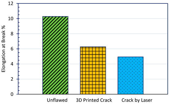
Figure 11.
The strain exhibited by the tested samples at the point of failure, indicating elongation at break.
The ability of the material to absorb the energy of the specimens demonstrated a similar pattern to elongation at break, as depicted in Figure 12, which was estimated through the stress–strain curve by using the concept of the area under the curve (AUC). Toughness represents the ability of a material to absorb energy before it fractures. The AUC of the stress–strain curve measures the material’s energy absorption capacity [57]. The results indicate a substantial reduction in toughness for the printed flawed specimens, at an observed decrease of 52% compared to that of the intact sample. Moreover, the laser-cracked sample exhibited an even more significant reduction in toughness, with a remarkable decrease of 77%. This decrease in toughness can be attributed to both the reduced strain and load at failure observed in the flawed specimens. Flaws or defects in 3D-printed PLA objects can have a detrimental effect on elongation at break, reducing the material’s ability to deform under tension before fracturing [58]; like stress concentration that results from voids, gaps, or inconsistent filament melting, can act as stress concentrators. When the material is subjected to tension, stress tends to concentrate in these flawed regions, leading to premature failure and reduced elongation at break. Additionally, flaws can disrupt the continuity of the material, leading to weakened mechanical properties. Discontinuities like air gaps, incomplete filament fusion, or layer shifting can create weak points that compromise the overall strength and elongation at break and, thus, can introduce brittleness to the 3D-printed PLA, resulting in reduced elongation at break compared to a flaw-free specimen that would have a more ductile response.
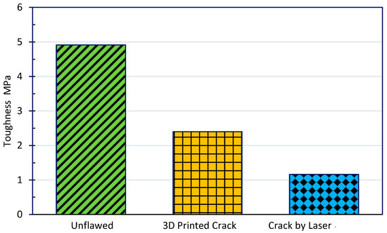
Figure 12.
Toughness characteristics.
Notably, the toughness of the specimens has a much more pronounced effect on the elongation at break and toughness properties than the impact on the ultimate stress, which is illustrated in Figure 13. The observed toughness decrease is directly linked to the reduced ability of the cracked samples to absorb and dissipate energy during impact events. The drop in strain and load at failure significantly impairs the samples’ ability to withstand and moderate the effects of absorbing impact loads, ultimately resulting in decreased toughness. These findings highlight the consequence of considering the specimen type and the corresponding presence of flaws when evaluating the toughness of components produced by additive manufacturing, especially FFF. Understanding the variations in toughness and elongation at break provides valuable understanding that can be used in designing and optimizing materials and structures with the ability of a material to absorb energy, thus ensuring the reliability and durability of printed parts in real-world applications. Flaws in 3D-printed parts can have a significant impact on their toughness since they act as stress concentrators that amplify stress and weaken the material around them. This can lead to a reduction in the overall strength of the 3D-printed part. As a crack propagates through the material, it can cause local failure and compromise the structural integrity of the part [59,60]. Additionally, flaws can reduce the toughness by creating areas of stress concentration and initiating failure at lower stress levels. The presence of cracks provides a pathway for stress to concentrate and propagate, reducing the material’s ability to absorb energy before fracture occurs. Cracked 3D-printed parts are more susceptible to complete fracture and catastrophic failure [61]. Once a crack initiates, it can propagate rapidly through the material under applied stress, leading to sudden and unexpected failure. The presence of cracks can compromise the structural integrity and reliability of the part, making it more prone to fracturing under normal operating conditions.
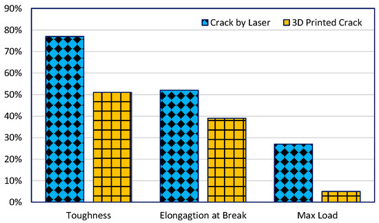
Figure 13.
Elongation at break and toughness characteristics: flawed vs. unflawed specimens.
Comprehensive analyses were carried out to thoroughly investigate the underlying factors contributing to the small load observed at the failure load levels of the flawed specimens. Two theoretical analyses were conducted, a Linear Elastic Fracture Mechanics analysis and a stress concentration analysis. These analyses aimed to explore the root causes of the observed phenomenon.
3.1. Stress Concentration Analysis
In the stress concentration analysis, the ultimate observed stress was estimated for the tested samples using the following equation, which is mentioned in Reference [62]:
where is the nominal stress (MPa), is the ultimate stress (MPa), and is the factor of stress concentration.
This formula allowed us to estimate the highest stress experienced within the samples under investigation. By assessing the stress concentration, we could gain insights into the localized areas that experienced elevated stress levels, which may have contributed to the failure at lower loads.
3.2. Fracture Mechanics Analysis
Linear Elastic Fracture Mechanics (LEFM) is a theoretical framework used to analyze and predict the behavior of cracked materials under applied loads [63]. While LEFM is widely used in the analysis of traditional materials, its application to 3D-printed parts requires specific considerations due to the unique characteristics of additive manufacturing processes [64]. In the context of 3D-printed parts, LEFM can be used to assess the structural integrity and fracture resistance of components that may contain inherent or manufacturing-induced defects, such as cracks or voids [65]. In this investigation, to enhance the primary awareness of the flaw propagation performance, the Linear Elastic Fracture Mechanics analysis was conducted to demonstrate its effect on the load-bearing capacity of the samples. By applying the principles of LEFM, we aimed to elucidate the fracture mechanics behind the observed low-load failure. This analysis encompassed a comprehensive examination of factors such as flaw length, material properties, and applied load, all of which play pivotal roles in determining a sample’s fracture toughness. Through the combined application of the stress concentration analysis and LEFM, we sought to shed light on the intricate mechanisms at play, leading to the diminished load capacity observed at the failure load of the flawed specimens. This approach allowed for a more detailed investigation into the phenomenon, enabling a comprehensive understanding of the factors contributing to the observed low-load failure.
In the case of the cracked samples with an elliptical crack configuration characterized by a one-to-half aspect ratio, the predictable stress concentration factor was found to be 3.96. This implies that both the 3D-printed flawed specimens and the laser-cracked specimens produced by the laser process experienced stress approximately four times higher than nominal stresses. However, it was perceived that the samples with flaws created by the laser process experienced a failure at stresses lower than that experienced by the specimens produced by the direct printing process, despite having similar stress levels.
The estimated nominal and maximum stresses observed are illustrated in Figure 14 for the tested specimens. It is evident in the figure that, by analyzing the nominal stress, the specimens with printed flaws exhibited higher ultimate stress levels than the laser-cracked samples. Consequently, this inconsistency in stress distribution led to a lower failure load for the specimens produced by the laser process, as previously discussed and represented in Figure 4. The standard deviations were estimated for the intact, 3D-printed cracked, and laser-cracked samples, and they were found to be 8.27, 6.95, and 5.20, respectively. Regarding the coefficients of variation (CVs), the calculated values of the three types of tested samples at the average maximum stress were 0.1583, 0.0265, and 0.0258, respectively. However, the CVs for the average normal stresses were 0.1583, 0.1047, and 0.1019, respectively.
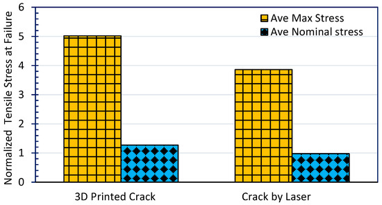
Figure 14.
The normalized highest tensile stress observed at the point of failure.
By examining the stress distribution and comparing the specimens with printed flaws to the specimens produced by the laser process, it became evident that the printed cracked samples experienced higher levels of stress, contributing to their higher failure load. However, despite having a similar stress concentration factor, the laser-cracked samples had lower maximum stresses, resulting in a lower load capacity and earlier failure. This discrepancy highlights the significance of stress distribution and its impact on the load-bearing capabilities of the cracked samples, further reinforcing the earlier observations and supporting the notion that multiple factors were at play in the failure behavior of the different sample configurations.
The analysis of the stress concentration demonstrated a disagreement with the observed failure. According to conventional reasoning, the laser-cracked samples should exhibit higher or at least equal levels of stress compared to the printed cracked samples. However, the empirical evidence suggests otherwise. To delve more into the underlying causes of this contradiction and further understand the failure mechanisms, we used LEFM in this study. In order to assess the grounds of the failure, the stress intensity factor at opening mode (i.e., Mode I) was estimated for each of the produced samples. This calculation involves utilizing a formula referenced from [66]:
where = axial stress (MPa); = the length of the crack (m); and = the correlation between the specimen’s geometry and crack length, which is influenced by various factors.
The Mode I SIF is a critical parameter in LEFM, as it quantifies the magnitude of the stress intensity associated with the opening or extension of a crack. By calculating the SIF, we aim to gain insights into the fracture behavior and understand the reasons behind the observed failure phenomena. By employing LEFM and evaluating the Mode I SIF, we can obtain a more comprehensive understanding of the failure characteristics of the printed samples. This approach allows us to analyze the stress intensity associated with crack propagation and provides valuable information about the samples’ fracture toughness. Through this analysis, we aim to bridge the gap between the contradiction observed in stress concentration justifications and the actual behavior of the laser and printed cracked samples, thus shedding light on the underlying factors responsible for the observed failure patterns.
Figure 15 clearly demonstrates a remarkable trend regarding the estimated stress intensity factor, normalized considering the unflawed and flawed specimens produced through different manufacturing methods, such as 3D printing and laser cutting. Remarkably, the SIF values for the intact samples are consistently better than those of the cracked samples, regardless of the manufacturing technique employed. This implies that the intact parts exhibit a more excellent resistance to crack extension than the defective components. Furthermore, when comparing the normalized SIF values of the flawed specimens, specifically those produced by 3D printing and those produced by the laser process, it becomes evident that the former exhibits higher SIF values. This discrepancy indicates that the laser-cut cracked samples possess a lower propensity for crack extension.
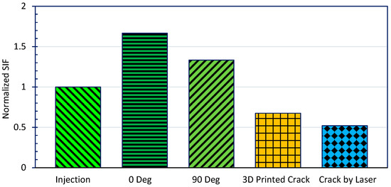
Figure 15.
Stress intensity factor (normalized) for PLA material when produced using various manufacturing methods.
Consequently, this discrepancy explains the observed phenomenon where the flawed specimens produced by the laser process exhibit a higher failure load than the specimens produced by 3D printing [67]. Analyzing the normalized stress intensity factor provides valuable insights into the fracture behavior of the samples. The intact samples demonstrate a superior ability to withstand crack extension, while the laser-cut cracked samples exhibit a reduced tendency for crack propagation compared to their 3D-printed counterparts. These findings shed light on the mechanical and failure characteristics of the tested specimens, enabling a deeper understanding of their behavior under stress and contributing to the overall comprehension of the effects of different manufacturing methods on sample integrity.
Furthermore, it was noticed that, in the case of the identical flaw characteristics and dimensions employed in the current investigation, there was a positive influence due to the effect of the 3D printing, which resulted in a flaw configuration surrounded by contours that were produced by the extrusion process, effectively creating a bridging stream to the stresses around the flaw configuration. The preferred bridging effect [68] contributed to additional resistance against crack extension. However, the flawed specimens produced through the laser process had their extruded contours severed by the laser, which facilitated flaw propagation. As a result, the laser-cut samples experienced a lower failure load and exhibited a smaller SIF. The existence of bridging in the 3D-printed flawed specimens played a crucial role in impeding crack growth. The extruded filament contours acted as a barrier, restraining the crack from extending further. This phenomenon led to a higher load-bearing capacity for the 3D-printed cracked samples. Cracks in 3D-printed parts have a direct impact on the stress intensity factor (SIF). The stress intensity factor is a parameter that describes the magnitude of stress near the tip of a crack and determines the crack growth behavior [69]. The stress intensity factor influences crack propagation behavior. In 3D-printed parts, cracks can initiate and propagate due to factors like material defects, improper printing parameters, or applied loads. When a tensile or bending load is applied to a cracked 3D-printed part, the stress intensity factor at the crack tip determines the likelihood of crack growth [70]. If the stress intensity factor exceeds a certain threshold, the crack will propagate, leading to reduced structural integrity and potentially catastrophic failure.
In contrast, the laser-cut samples lacked this bridging effect, as the laser process had already severed the extruded filaments along the crack path. Consequently, the absence of bridging [71] promoted crack propagation, resulting in a lower failure load and a reduced stress intensity factor. These observations provide a clear explanation for the observed differences in the failure behavior between the 3D-printed flawed specimens and the specimens produced by the laser process. The unique characteristics of the crack profiles formed by each manufacturing method significantly influenced the resistance to crack extension and, consequently, the failure load. The bridging effect in the 3D-printed flawed specimens enhanced their structural integrity. At the same time, the absence of bridging in the laser-cut samples contributed to their diminished load-bearing capacity and lower stress intensity factor. These findings provide scientific justification for the observed differences in failure behavior and mechanical properties between the flawed specimens made by FFF and those made by the laser process. It was observed that there was a significant negative impact of the laser process on failure load, elongation at break, and toughness, which can be attributed to the introduction of flaws, stress concentrations, and microstructural changes during the cutting process. In contrast, the extruded filament contours in the 3D-printed cracked samples enhanced their crack resistance and mechanical integrity. Understanding these effects is important for optimizing manufacturing processes and selecting appropriate techniques for producing crack-resistant components. It allows for identifying potential failure mechanisms and developing strategies to improve the structural integrity and performance of 3D-printed materials subjected to crack-inducing conditions.
4. Finite Element Analysis
The Finite Element Analysis (FEA) played a central role in this study, facilitating an in-depth examination of the stress distribution in the tested samples. The investigation focused on two primary FE models. Firstly, a solid homogeneous material model was employed to analyze the behavior of the dog-bone specimen under uniaxial tensile stress. This analysis was conducted twice: once without any cracks in the specimen and another time with the inclusion of a central crack. The stress parameters of utmost interest, namely, the principal stresses, maximum shear stress, and von Mises stress, were meticulously estimated along the central line of the specimen for the intact sample. Additionally, for the flawed sample with the central crack, the stress distribution was thoroughly assessed in the vicinity of the crack [72]. These data points offered invaluable insights into how the presence of the crack influenced the stress patterns and potential failure regions within the material. By employing FEA to investigate such intricate stress-related aspects, this study provides a comprehensive understanding of the mechanical response of the dog-bone specimens, shedding light on crucial factors affecting their structural integrity and mechanical performance. Figure 16 shows the mesh used for the modeling using ANSYS as well as the Boundary Conditions (BCs) of the full-scale model, where the number of elements and the total number of nodes used were 164,890 and 725,655, respectively.
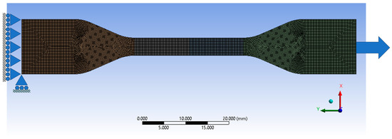
Figure 16.
FE mesh and BCs for the full-scale intact specimen modeled using ANSYS.
In this investigation, our focus centers on three fundamental types of stress: principal stress, max shear stress, and von Mises stress. These stress concepts are pivotal in mechanics and stress analyses, enabling us to comprehend how materials respond to various loading conditions. Understanding the intricacies of principal stress, which encompasses the maximum and minimum normal stresses along specific planes, allows us to pinpoint critical areas within structures. The max shear stress, exemplifying the greatest intensity of shear stress at any given point, provides invaluable insights into potential sliding or deformation issues [73]. Finally, the von Mises stress, a comprehensive criterion combining normal and shear stresses, is a robust measure to evaluate material yielding or failure under complex loading scenarios. By examining these stress types, engineers and designers gain essential knowledge for ensuring the safety and optimal performance of materials and structures in diverse applications.
For the intact case, the evidence presented in Figure 17 obviously indicates that the maximum von Misses stresses concentrate precisely at the transition section between the shoulder and the narrow segment. This pivotal finding provides a compelling explanation for the experimental failure observed in the dog-bone sample. The stress concentration at this specific location underscores its critical role in determining the structural integrity of the sample under investigation. Such valuable insights from the data shed light on the underlying mechanics and failure mechanisms, enabling us to make informed decisions and implement necessary design improvements to avert potential failures in similar components [74]. The stress analysis at the narrow section, corresponding to the gauge length of the sample, reveals a remarkable convergence between the experimental and theoretical findings. Specifically, the measured stress registers at approximately 124.78 MPa, demonstrating an exceptionally close alignment with the calculated theoretical stress of 125 MPa, derived from the normal stress calculations. This correspondence between empirical and theoretical data attests to the accuracy and precision of our stress analysis methodologies. Such a comparison instills confidence in the validity of our experimental results and the reliability of the stress calculations, confirming our investigation’s scientific accuracy and integrity.
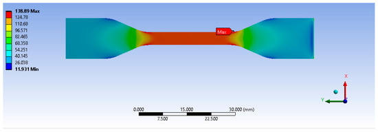
Figure 17.
FE principal stress distribution through the intact sample.
In the case of the cracked specimen, the geometry and dimensions of the through-thickness flaw were carefully modeled using the Finite Element Analysis (FEA), as illustrated in Figure 18. This advanced simulation technique allows one to capture the flaw deformation and behavior and to understand how the crack propagates under different loading conditions. It enables a comprehensive understanding of its impact on the overall specimen integrity [75]. This thorough and precise modeling approach allows one to explore potential failure mechanisms and devise effective strategies to enhance the specimen’s resistance against crack propagation, contributing to safer and more reliable engineering designs for 3D-printed components.
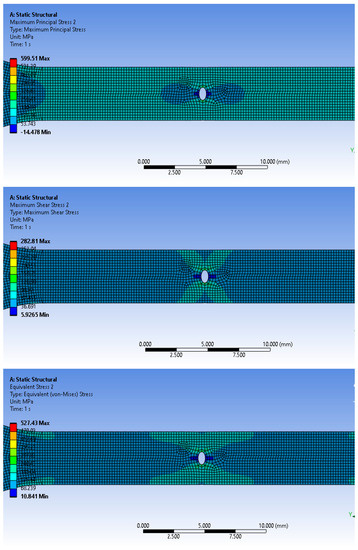
Figure 18.
FEA results for principal, max shear, and von Misses stress for the flawed sample.
Figure 19 presents a comprehensive plot depicting the three critical stresses along the central section of the flawed specimen. Compared to the intact scenario, the stresses were thoroughly normalized to comprehend the flaw influence on stress distribution. This normalization process allows for a direct and meaningful comparison, and we can gain valuable insights into how the presence of the flaw alters the stress patterns, enabling us to assess the structural integrity and potential failure risks more accurately. The results reveal a significant stress increase, with values rising 3.5 times higher than the normal stresses estimated for the intact case [76]. This effect is most pronounced at the edge of the flaw, leading to a remarkable concentration of stresses in this region. Unfortunately, this heightened stress concentration precipitates the experimental failure of the specimen. The apparent link between the intensified stresses and the flaw presence underscores its critical role as the primary mechanism for specimen failure. This crucial finding highlights the importance of stress analyses and flaw detection in ensuring structural reliability and safety in engineering applications [77].
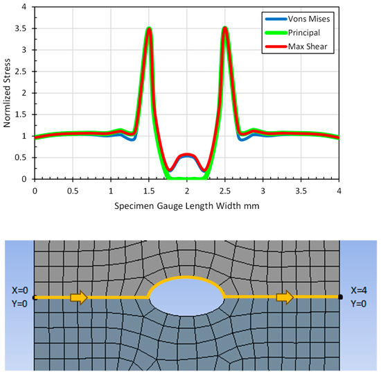
Figure 19.
Normalized stresses estimated at the central section of the flawed specimen around the flaw.
5. Implementation of FFF in Construction Application
The implementation of Fused Filament Fabrication (FFF) within the construction industry represents a transformative concept shift, offering innovative solutions to traditional building methods [17]. In general, the FFF process, commonly known as 3D printing, involves the layer-by-layer deposition of thermoplastic materials to create three-dimensional structures that can be applied in construction:
Customization and Complex Geometry: FFF enables the fabrication of intricate, customized architectural designs that were previously challenging to achieve using conventional methods. Complex geometries, such as curved walls, intricate facades, and interlocking structural elements, can be realized with relative ease, enhancing design freedom and creativity [78].
Rapid Prototyping and Iterative Design: FFF assists architects and engineers in quickly prototyping and iterating designs, facilitating a more efficient design process. This speed and flexibility enable the exploration of multiple design variations, leading to optimized structures with reduced material waste.
Reduced Material Waste: Traditional construction often generates significant material waste due to cutting and shaping processes. However, FFF employs an additive manufacturing approach, where material is deposited only where needed. This minimizes waste, making the process more environmentally sustainable [79].
On-Site and Remote Printing: The portability and flexibility of FFF make it feasible for the on-site printing of construction components. This can significantly reduce transportation costs and the logistical challenges associated with transporting pre-fabricated parts. Moreover, remote or off-site printing can also be employed to fabricate components in controlled environments and then transport them to the construction site.
Sustainable Construction: FFF can accommodate the use of eco-friendly and recycled materials, contributing to sustainable construction practices. Additionally, the ability to optimize designs for material efficiency can lead to reduced overall resource consumption [80].
Speed and Efficiency: While traditional construction can be time-consuming, FFF offers a faster construction process. As layers are added sequentially, the printing process can be highly automated, allowing for daily operation and quicker project completion.
Reduced Labor Intensity: Automated FFF systems require minimal human labor during the printing process, reducing the need for extensive manual labor and potentially mitigating labor shortages [81].
Maintenance and Retrofitting: FFF can be utilized for creating replacements for damaged or outdated building components. This approach is particularly beneficial for historical preservation, where intricate architectural details can be accurately replicated.
Structural Innovations: FFF opens the door to experimenting with new structural designs and configurations, potentially leading to novel load-bearing mechanisms and resilient structures.
Challenges and Considerations: Despite its numerous advantages, FFF in construction faces challenges such as material compatibility, quality control, scalability, regulatory compliance, and addressing issues like layer adhesion and printing consistency. These challenges require ongoing research and development efforts.
6. Conclusions
This study’s findings show that the laser had a detrimental effect on the degradation of the mechanical and failure characteristics of the specimens in comparison to the specimens made by FFF. Notably, it was evident that the negative impact affected three key aspects: failure load, elongation at break, and toughness.
- The failure load of the specimens with flaws that were made by the laser process was significantly reduced compared to that of the 3D-printed flawed samples. This decrease in failure load indicates a diminished ability of the laser-cut samples to withstand applied loads before experiencing failure. This finding can be attributed to the inherent characteristics of the laser-cutting process, which may introduce flaws or weaken the material structure near the crack, thereby reducing its load-bearing capacity.
- The elongation at break of the laser-cut cracked samples was compromised, indicating a reduced capability for plastic deformation before fracture. The laser-cutting process may introduce stress concentrations or microstructural changes that hinder the material’s ability to undergo plastic deformation. This, in turn, leads to decreased elongation at break and more brittle fracture behavior.
- Furthermore, the laser-cut cracked samples exhibited reduced toughness compared to the 3D-printed cracked samples. With localized heating and potential for inducing microstructural changes, the laser-cutting process can negatively affect the material’s toughness, making it more susceptible to brittle fracture.
- The specimens with flaws made by FFF demonstrated superior aspects compared to the flawed samples produced by a laser. A key contributing factor was the presence of contours due to extruded filament, which enveloped the flaw geometry, resulting from the 3D printing slicing process. These filament contours acted as crack-bridging mechanisms, effectively redirecting the stress distribution around the crack and enhancing the sample’s resistance to crack propagation.
- Moreover, when applying Linear Elastic Fracture Mechanics to analyze Mode-I SIF, it was observed that the specimens with flaws produced by the laser process exhibited decreased levels compared to the printed flawed specimens. Mainly, SIF is a critical factor in determining the crack growth and failure propensity. The lower stress intensity factor observed in the laser-cut cracks explains the more moderate load failure observed in these samples. This can be attributed to the specific crack geometry and the localized stress concentration factors associated with the laser-cutting process [82].
Author Contributions
Conceptualization, W.A.; Methodology, W.A. and A.E.H.; Software, A.E.H.; Validation, E.Z.; Formal analysis, W.A. and E.Z.; Investigation, E.Z.; Data curation, A.E.H.; Writing—original draft, W.A.; Writing—review & editing, E.Z.; Supervision, W.A.; Funding acquisition, W.A. All authors have read and agreed to the published version of the manuscript.
Funding
This research received UAEU funding G00003693.
Data Availability Statement
Data available on request.
Conflicts of Interest
The authors declare no conflict of interest.
References
- Jones, R.; Smith, T. Integrating 3D Printing into Mechanical Engineering Education. In Advances in Engineering Education; Johnson, M., Ed.; John Wiley & Sons, Inc.: Hoboken, NJ, USA, 2021; pp. 87–102. [Google Scholar]
- Smith, J.; Johnson, A. Innovations in Three-Dimensional Printing of Ceramic Powders. In Advances in Ceramic Materials and Applications; Patel, R., Ed.; Springer: Berlin/Heidelberg, Germany, 2020; pp. 123–145. [Google Scholar]
- Wang, X.C.; Wei, J.; Yi, X.B.; Zhang, J.; Shang, K.; Wang, Q. 3D Printing Technology and the Adaptability of Printing Material. Appl. Mech. Mater. 2014, 633–634, 569–573. [Google Scholar] [CrossRef]
- Hao, B.; Lin, G. 3D Printing Technology and Its Application in Industrial Manufacturing. IOP Conf. Ser. Mater. Sci. Eng. 2020, 782, 022065. [Google Scholar] [CrossRef]
- Ziemianski, D.; Thimm, G.; Kelly, D. Structural integrity assessment of additive manufactured components. J. Mater. Process. Technol. 2019, 267, 270–287. [Google Scholar]
- Gibson, I.; Rosen, D.W.; Stucker, B. Additive Manufacturing Technologies: Rapid Prototyping to Direct Digital Manufacturing; Springer: New York, NY, USA, 2010. [Google Scholar] [CrossRef]
- Mumtaz, K. Additive Manufacturing of Metals: The Technology, Materials, Design and Production L. Yang et al. Springer. 2017. 168pp. Illustrated. £69.99. ISBN 978-3-319-55127-2. Aeronaut. J. 2018, 122, 861–862. [Google Scholar] [CrossRef][Green Version]
- Hague, R.; Dickens, P.; Hopkinson, N. (Eds.) Rapid Manufacturing; An Industrial Revolution for the Digital Age; John Wiley & Sons, Inc.: Hoboken, NJ, USA, 2006; Volume 30. [Google Scholar]
- Praveena, B.A.; Lokesh, N.; Buradi, A.; Santhosh, N.; Praveena, B.L.; Vignesh, R. A comprehensive review of emerging additive manufacturing (3D printing technology): Methods, materials, applications, challenges, trends and future potential. Mater. Today Proc. 2022, 52, 1309–1313. [Google Scholar] [CrossRef]
- Chatham, C.A.; Long, T.E.; Williams, C.B. A review of the process physics and material screening methods for polymer powder bed fusion additive manufacturing. Prog. Polym. Sci. 2019, 93, 68–95. [Google Scholar] [CrossRef]
- Lim, S.; Buswell, R.A.; Le, T.T.; Austin, S.A. Developments in construction-scale additive manufacturing processes. Autom. Constr. 2012, 21, 262–268. [Google Scholar] [CrossRef]
- Salet, T.; Bos, F.; Wolfs, R. 3D concrete printing: Machine and mix design, printing process and hydration mechanism. Cem. Concr. Res. 2016, 112, 59–67. [Google Scholar] [CrossRef]
- Khoshnevis, B. Automated construction by contour crafting—Related robotics and information technologies. Autom. Constr. 2004, 13, 5–19. [Google Scholar] [CrossRef]
- Wang, X.; Li, V.C.; Wu, C. Developments and prospects of 3D printed cementitious materials. Cem. Concr. Res. 2017, 103, 115–124. [Google Scholar] [CrossRef]
- Khorshidi, A.M.; Seifi, M.; Toyserkani, E. A review of materials and methods used for 3D printing in the construction industry. Constr. Build. Mater. 2019, 221, 831–846. [Google Scholar] [CrossRef]
- Placzek, G.; Schwerdtner, P. Concrete Additive Manufacturing in Construction: Integration Based on Component-Related Fabrication Strategies. Buildings 2023, 13, 1769. [Google Scholar] [CrossRef]
- Arrêteau, M.; Fabien, A.; El Haddaji, B.; Chateigner, D.; Sonebi, M.; Sebaibi, N. Review of Advances in 3D Printing Technology of Cementitious Materials: Key Printing Parameters and Properties Characterization. Buildings 2023, 13, 1828. [Google Scholar] [CrossRef]
- Shafighfard, T.; Cender, T.A.; Demir, E. Additive manufacturing of compliance optimized variable stiffness composites through short fiber alignment along curvilinear paths. Addit. Manuf. 2021, 37, 101728. [Google Scholar] [CrossRef]
- Anderson, T.L.; Suresh, S. A concise history of fracture mechanics. Int. J. Fract. 2001, 110, 1–24. [Google Scholar]
- Brown, S.; Johnson, R. Introduction to Elementary Engineering Fracture Mechanics. In Fundamentals of Fracture Mechanics in Engineering Applications; Smith, J., Ed.; Springer: Berlin/Heidelberg, Germany, 2022; pp. 45–67. [Google Scholar]
- Roberts, A.; Davis, B. Cracked Microparticles in Particulate Composites: Effects on Mechanical Properties and Fracture Behavior. In Advanced Composites: Materials, Manufacturing, and Applications; Thompson, M., Ed.; John Wiley & Sons, Inc.: Hoboken, NJ, USA, 2021; pp. 215–235. [Google Scholar]
- Smith, J.; Wilson, A. Characterization of Fractured Particulate Reinforced Composites. In Advanced Composite Materials: Characterization and Applications; Johnson, R., Ed.; Springer: Berlin/Heidelberg, Germany, 2022; pp. 75–95. [Google Scholar]
- Wahab, M.A. Finite Elements in Fracture Mechanics: For General Power Type Singularity Problems; LAP Lambert Academic Publishing: Saarbrücken, Germany, 2010. [Google Scholar]
- Miller, C.; Thompson, R. Fracture Analysis and Load-Carrying Capacity of Cracked Components in 3D Printing. In Advances in Fracture Mechanics: Methods, Applications, and Case Studies; Wilson, A., Ed.; Elsevier: Amsterdam, The Netherlands, 2021; pp. 165–185. [Google Scholar]
- Ishii, K.; Todoroki, A.; Mizutani, Y.; Suzuki, Y.; Koga, Y.; Matsuzaki, R.; Ueda, M.; Hirano, Y. Bending fracture rule for 3D-printed curved continuous-fiber composite. Adv. Compos. Mater. 2019, 28, 383–395. [Google Scholar] [CrossRef]
- Xu, Y.; Zhang, H.; Šavija, B.; Chaves Figueiredo, S.; Schlangen, E. Deformation and fracture of 3D printed disordered lattice materials: Experiments and modeling. Mater. Des. 2019, 162, 143–153. [Google Scholar] [CrossRef]
- Allum, J.; Gleadall, A.; Silberschmidt, V.V. Fracture of 3D-printed polymers: Crucial role of filament-scale geometric features. Eng. Fract. Mech. 2020, 224, 106818. [Google Scholar] [CrossRef]
- Gardan, J.; Makke, A.; Recho, N. Improving the fracture toughness of 3D printed thermoplastic polymers by fused deposition modeling. Int. J. Fract. 2018, 210, 1–15. [Google Scholar] [CrossRef]
- Aliheidari, N.; Tripuraneni, R.; Ameli, A.; Nadimpalli, S. Fracture resistance measurement of fused deposition modeling 3D printed polymers. Polym. Test. 2017, 60, 94–101. [Google Scholar] [CrossRef]
- Noori, H. Interlayer fracture energy of 3D-printed PLA material. Int. J. Adv. Manuf. Technol. 2019, 101, 1959–1965. [Google Scholar] [CrossRef]
- Zolfagharian, A.; Khosravani, M.R.; Kaynak, A. Fracture Resistance Analysis of 3D-Printed Polymers. Polymers 2020, 12, 302. [Google Scholar] [CrossRef]
- Cuesta, I.I.; Martinez-Pañeda, E.; Díaz, A.; Alegre, J.M. The Essential Work of Fracture parameters for 3D printed polymer sheets. Mater. Des. 2019, 181, 107968. [Google Scholar] [CrossRef]
- Gendviliene, I.; Simoliunas, E.; Rekstyte, S.; Malinauskas, M.; Zaleckas, L.; Jegelevicius, D.; Bukelskiene, V.; Rutkunas, V. Assessment of the morphology and dimensional accuracy of 3D printed PLA and PLA/HAP scaffolds. J. Mech. Behav. Biomed. Mater. 2020, 104, 103616. [Google Scholar] [CrossRef] [PubMed]
- Ahmed, W.K.; Al-Rifaie, W.N. The impact of cracked microparticles on the mechanical and the fracture behavior of particulate composite. J. Nano Electron. Phys. 2015, 7, 03008. [Google Scholar]
- Li, H.; Geng, X.; Huang, L.; Liu, J.; Jia, K.; Xue, Z.; Aydeng, A. Effect of surface quality on the fracture behavior of 3d printed lattice structures. CIRP J. Manuf. Sci. Technol. 2023, 43, 170–180. [Google Scholar] [CrossRef]
- Maurizi, M.; Edwards, B.W.; Gao, C.; Greer, J.R.; Berto, F. Fracture resistance of 3d nano-architected lattice materials. Extrem. Mech. Lett. 2022, 56, 101883. [Google Scholar] [CrossRef]
- Maliaris, G.; Sarafis, E. Mechanical behavior of 3d printed stochastic lattice structures. Solid State Phenom. 2017, 258, 225–228. [Google Scholar] [CrossRef]
- Peloquin, J.; Kirillova, A.; Rudin, C.; Brinson, L.C.; Gall, K. Prediction of tensile performance for 3d printed photopolymer gyroid lattices using structural porosity, base material properties, and machine learning. Mater. Des. 2023, 232, 112126. [Google Scholar] [CrossRef]
- Hamano, R.; Nakagawa, Y.; Irawan, V.; Ikoma, T. Mechanical anisotropy and fracture mode of binder jetting 3d printed calcium sulfate moldings. Appl. Mater. Today 2021, 25, 101160. [Google Scholar] [CrossRef]
- Ameri, B.; Taheri-Behrooz, F.; Aliha, M.R.M. Evaluation of the geometrical discontinuity effect on mixed-mode i/ii fracture load of fdm 3d-printed parts. Theor. Appl. Fract. Mech. 2021, 113, 102953. [Google Scholar] [CrossRef]
- Wang, P.; Zou, B.; Ding, S.; Li, L.; Huang, C. Effects of fdm-3d printing parameters on mechanical properties and microstructure of cf/peek and gf/peek. Chin. J. Aeronaut. 2021, 34, 236–246. [Google Scholar] [CrossRef]
- Naveed, N. Investigating the Material Properties and Microstructural Changes of Fused Filament Fabricated PLA and Tough-PLA Parts. Polymers 2021, 13, 1487. [Google Scholar] [CrossRef] [PubMed]
- Xu, L.R.; Wang, Q.; Ni, Y.; Zhang, G.; Liu, F.; Zheng, X.; Liu, Y. Significant Shear Failure Difference among Additively Manufactured Polymers Using Different Techniques. Polymers 2022, 14, 4028. [Google Scholar] [CrossRef] [PubMed]
- Saleh, M.; Anwar, S.; Al-Ahmari, A.M.; Alfaify, A. Compression Performance and Failure Analysis of 3D-Printed Carbon Fiber/PLA Composite TPMS Lattice Structures. Polymers 2022, 14, 4595. [Google Scholar] [CrossRef] [PubMed]
- D’Andrea, D.; Risitano, G.; Raffaele, M.; Cucinotta, F.; Santonocito, D. Damage assessment of different fdm-processed materials adopting infrared thermography. Frat. Integrità Strutt. 2022, 16, 75–90. [Google Scholar] [CrossRef]
- Ultimaker PLA Data Sheet. Available online: https://ultimaker.com/materials/s-series-pla/ (accessed on 13 June 2023).
- ASTM D638-22; Standard Test Method for Tensile Properties of Plastics. ASTM: West Conshohocken, PA, USA, 2022.
- Sharma, V.; Roozbahani, H.; Alizadeh, M.; Handroos, H. 3d printing of plant-derived compounds and a proposed nozzle design for the more effective 3d fdm printing. IEEE Access 2021, 9, 57107–57119. [Google Scholar] [CrossRef]
- El Hassan, A.; Ahmed, W.; Zaneldin, E. Investigating the Impact of Inclusions on the Behavior of 3D-Printed Composite Sandwich Beams. Buildings 2022, 12, 1448. [Google Scholar] [CrossRef]
- Zaneldin, E.; Ahmed, W.; Mansour, A.; Hassan, A.E. Dimensional Stability of 3D Printed Objects Made from Plastic Waste Using FDM: Potential Construction Applications. Buildings 2021, 11, 516. [Google Scholar] [CrossRef]
- Ouassil, S.E.; El Magri, A.; Vanaei, H.R.; Vaudreuil, S. Investigating the effect of printing conditions and annealing on the porosity and tensile behavior of 3D-printed polyetherimide material in Z-direction. Appl. Polym. Sci. 2023, 140, e53353. [Google Scholar] [CrossRef]
- Vanaei, H.R.; Magri, A.E.; Rastak, M.A.; Vanaei, S.; Vaudreuil, S.; Tcharkhtchi, A. Numerical–Experimental Analysis toward the Strain Rate Sensitivity of 3D-Printed Nylon Reinforced by Short Carbon Fiber. Materials 2022, 15, 8722. [Google Scholar] [CrossRef] [PubMed]
- Marșavina, L.; Vălean, C.; Mărghitaș, M.; Linul, E.; Razavi, N.; Berto, F.; Brighenti, R. Effect of the manufacturing parameters on the tensile and fracture properties of fdm 3d-printed pla specimens. Eng. Fract. Mech. 2022, 274, 108766. [Google Scholar] [CrossRef]
- Kizhakkinan, U.; Rosen, D.W.; Raghavan, N. Experimental investigation of fracture toughness of fused deposition modeling 3d-printed pla parts. Mater. Today Proc. 2022, 70, 631–637. [Google Scholar] [CrossRef]
- Jia, Z.; Wang, L. 3d printing of biomimetic composites with improved fracture toughness. Acta Mater. 2019, 173, 61–73. [Google Scholar] [CrossRef]
- Budiansky, B.; Amazigo, J.C.; Evans, A.G. Small-scale crack bridging and the fracture 39 toughness of particulate-reinforced ceramics. J. Mech. Phys. Solids 1988, 36, 167–187. [Google Scholar] [CrossRef]
- Ashby, M.F.; Jones, D.R.H. Engineering Materials 1: An Introduction to Properties, Applications, and Design; Butterworth–Heinemann: Oxford, UK, 2013. [Google Scholar]
- Al-Mazrouei, N.; Ismail, A.; Ahmed, W.; Al-Marzouqi, A.H. ABS/Silicon Dioxide Micro Particulate Composite from 3D Printing Polymeric Waste. Polymers 2022, 14, 509. [Google Scholar] [CrossRef] [PubMed]
- Tao, Y.; Kong, F.; Li, Z.; Zhang, J.; Zhao, X.; Yin, Q.; Xing, D.; Li, P. A review on voids of 3D printed parts by fused filament fabrication. J. Mater. Res. Technol. 2021, 15, 4860–4879. [Google Scholar] [CrossRef]
- Ayatollahi, M.R.; Nabavi-Kivi, A.; Bahrami, B.; Yahya, M.Y.; Khosravani, M.R. The influence of in-plane raster angle on tensile and fracture strengths of 3D-printed PLA specimens. Eng. Fract. Mech. 2020, 237, 107225. [Google Scholar] [CrossRef]
- Aranda, M.; Reinoso, J.; García, I. On different 3D printing methods and fracture performance in DCB composite specimens including structured interfaces. Theor. Appl. Fract. Mech. 2022, 122, 103552. [Google Scholar] [CrossRef]
- Beer, F.P.; Johnston, E.R.; DeWolf, J.T. Mechanics of Materials; McGraw-Hill Higher Education: Boston, MA, USA, 2006. [Google Scholar]
- Edgar, J.; Tint, S. “Additive Manufacturing Technologies: 3D Printing, Rapid Prototyping, and Direct Digital Manufacturing”, 2nd Edition. Johns. Matthey Technol. Rev. 2015, 59, 193–198. [Google Scholar] [CrossRef]
- Huang, Y.; Leu, M.C.; Mazumder, J.; Donmez, A. Additive Manufacturing: Current State, Future Potential, Gaps and Needs, and Recommendations. J. Manuf. Sci. Eng. 2015, 137, 014001. [Google Scholar] [CrossRef]
- Ngo, T.D.; Kashani, A.; Imbalzano, G.; Nguyen, K.T.Q.; Hui, D. Additive Manufacturing (3D Printing): A Review of Materials, Methods, Applications and Challenges. Compos. Part B Eng. 2018, 143, 172–196. [Google Scholar] [CrossRef]
- Broek, D. The Practical Use of Fracture Mechanics; Kluwer Academic Publishers: Dordrecht, The Netherlands, 1997. [Google Scholar]
- Santos, J.D.; Guerrero, J.M.; Blanco, N.; Fajardo, J.I.; Paltán, C.A. Numerical and Experimental Analysis of the Mode I Interlaminar Fracture Toughness in Multidirectional 3D-Printed Thermoplastic Composites Reinforced with Continuous Carbon Fiber. Polymers 2023, 15, 2403. [Google Scholar] [CrossRef] [PubMed]
- Meng, Q.; Wang, T. An improved crack-bridging model for rigid particle-polymer composites. Eng. Fract. Mech. 2019, 211, 291–302. [Google Scholar] [CrossRef]
- Al-Mazrouei, N.; Al-Marzouqi, A.H.; Ahmed, W. Characterization and Sustainability Potential of Recycling 3D-Printed Nylon Composite Wastes. Sustainability 2022, 14, 10458. [Google Scholar] [CrossRef]
- Baechle-Clayton, M.; Loos, E.; Taheri, M.; Taheri, H. Failures and Flaws in Fused Deposition Modeling (FDM) Additively Manufactured Polymers and Composites. J. Compos. Sci. 2022, 6, 202. [Google Scholar] [CrossRef]
- Adel, M.; Jiradilok, P.; Matsumoto, K.; Nagai, K. Evaluation of crack-bridging strength degradation in SFRC structural beams under flexural fatigue. Compos. Struct. 2020, 244, 112267. [Google Scholar] [CrossRef]
- Bragaglia, M.; Cecchini, F.; Paleari, L.; Ferrara, M.; Rinaldi, M.; Nanni, F. Modeling the fracture behavior of 3D-printed PLA as a laminate composite: Influence of printing parameters on failure and mechanical properties. Compos. Struct. 2023, 322, 117379. [Google Scholar] [CrossRef]
- Zouaoui, M.; Gardan, J.; Lafon, P.; Makke, A.; Labergere, C.; Recho, N. A Finite Element Method to Predict the Mechanical Behavior of a Pre-Structured Material Manufactured by Fused Filament Fabrication in 3D Printing. Appl. Sci. 2021, 11, 5075. [Google Scholar] [CrossRef]
- Durlan, J.; Adrover, B.; Zandi, M.D.; Lluma, J.; Jerez, R.; Travieso, A.J. Finite element modelling and evaluation of mechanical properties of wood-PLA parts manufactured through Fused Filament Fabrication. IOP Conf. Ser. Mater. Sci. Eng. 2021, 1193, 012094. [Google Scholar] [CrossRef]
- Alharbi, M.; Kong, I.; Patel, V.I. Simulation of uniaxial stress–strain response of 3D-printed polylactic acid by nonlinear finite element analysis. Appl. Adhes. Sci. 2020, 8, 5. [Google Scholar] [CrossRef]
- Zwawi, M. Structure Integrity and Fracture Prediction of PLA 3D-Printed Eye Grab Hooks with Different Cross Sections. Procedia Struct. Integr. 2022, 37, 1057–1064. [Google Scholar] [CrossRef]
- Ahmed, W.; Alnajjar, F.; Zaneldin, E.; Al-Marzouqi, A.H.; Gochoo, M.; Khalid, S. Implementing FDM 3D Printing Strategies Using Natural Fibers to Produce Biomass Composite. Materials 2020, 13, 4065. [Google Scholar] [CrossRef]
- Alami, A.H.; Olabi, A.G.; Ayoub, M.; Aljaghoub, H.; Alasad, S.; Abdelkareem, M.A. 3D Concrete Printing: Recent Progress, Applications, Challenges, and Role in Achieving Sustainable Development Goals. Buildings 2023, 13, 924. [Google Scholar] [CrossRef]
- Bello, N.D.; Memari, A.M. Comparative Review of the Technology and Case Studies of 3D Concrete Printing of Buildings by Several Companies. Buildings 2023, 13, 106. [Google Scholar] [CrossRef]
- Cao, X.; Yu, S.; Cui, H.; Li, Z. 3D Printing Devices and Reinforcing Techniques for Extruded Cement-Based Materials: A Review. Buildings 2022, 12, 453. [Google Scholar] [CrossRef]
- Kaszyńska, M.; Skibicki, S.; Hoffmann, M. 3D Concrete Printing for Sustainable Construction. Energies 2020, 13, 6351. [Google Scholar] [CrossRef]
- Ahmed, W.K.; Teng, H. Characterisation of fractured particulate reinforced composite. Int. J. Microstruct. Mater. Prop. 2014, 9, 160–175. [Google Scholar] [CrossRef]


Disclaimer/Publisher’s Note: The statements, opinions and data contained in all publications are solely those of the individual author(s) and contributor(s) and not of MDPI and/or the editor(s). MDPI and/or the editor(s) disclaim responsibility for any injury to people or property resulting from any ideas, methods, instructions or products referred to in the content. |
© 2023 by the authors. Licensee MDPI, Basel, Switzerland. This article is an open access article distributed under the terms and conditions of the Creative Commons Attribution (CC BY) license (https://creativecommons.org/licenses/by/4.0/).