Abstract
To provide references for the fire prevention design of steel–concrete–steel immersed tube tunnels, four types of test conditions—no fire protection, fireproof coating insulation, single-layer seam fireproof boards, and double-layer seam fireproof boards—were carried out using partial full-size structural test members. Additionally, the thermal insulation effects of various fireproofing technology solutions were contrasted and analyzed. Combined with the numerical simulation analysis, the temperature distribution law inside the tube structure under various fireproofing measures and the temperature rise law of measuring points at different depths were studied, and the protective effect of the fireproof layers on the tube structure under high fire temperature was demonstrated. The results of the numerical simulation and the experimental data agree well. The results show that adding fireproof layers can significantly lower both the steel shell’s surface temperature and the depth of fire impact. Without fire protection, the surface temperature of the bottom steel shell exceeds 300 °C at 69 s, and the member bursts. The fireproof coatings are cracked and flaking and cannot meet the fire resistance limits. Both single-seam and double-seam schemes of calcium silicate boards can meet the fire resistance limit requirements and the latter has a better heat insulation effect.
1. Introduction
A brand-new kind of structure, the steel–concrete–steel composite structure, is formed of inner and exterior steel plates filled with concrete on both sides and the development direction of large immersed tube tunnels in the future. The inner concrete filling can prevent the steel plate from buckling, while the outer steel shell can prevent the concrete from cracking. This increases the structure’s bearing capacity and gives it better ductility, impact resistance, waterproof performance, and other qualities. Because the external steel shell of a steel–concrete–steel immersed tube tunnel is both waterproof and load-bearing [1,2], the stability and durability of the steel shell are crucial to the tunnel’s overall structural safety. Fire is one of the common disasters in tunnels. Once it happens, the temperature will exceed 1000 °C in a short time, causing serious damage to the tunnel structure [3]. The properties of steel at high temperatures change significantly. For example, at temperatures above 300 °C, steel’s mechanical properties start to deteriorate significantly, and at temperatures above 600 °C, ordinary steel structures lose most of their stiffness and strength and are susceptible to collapse at any time [4,5,6]. Therefore, steel–concrete–steel composite constructions transfer heat more quickly in high fire temperatures than traditional reinforced concrete structures, making them more prone to damage and requiring higher technical fire safety requirements.
The main means of studying the temperature distribution laws of tunnel lining structures at home and abroad are theoretical analysis, field tests, and numerical simulations. In terms of testing, Sheng Du et al. [7] constructed a 1/10 scale tunnel fire model to measure the surface and inside temperatures of the concrete lining during the fire test. Wang et al. [8] investigated the smoke temperature distribution alongside the lining across the section and the effects of pool sizes and fuels on it through a series of small-scale experiments. Yan et al. [9] conducted comprehensive experimental tests on the behavior of the reinforced concrete (RC) and the steel fiber reinforced concrete (SFRC) shield TBM (Tunnel Boring Machine) tunnel lining segments and the lining rings exposed to a standard HC (Hydrocarbon) curve. Jiang Shuping et al. [10] carried out high-temperature ablation tests of the members by using a partial 1:1 structural test member as well as different fire protection technologies (fireproof board and fireproof coating) and different fire protection schemes through a test platform established by their design, and determined a suitable fire protection technology scheme for reinforced concrete immersed tunnel structures. Wang et al. [11] presented details of field tunnel fire testing of concrete tunnel linings with and without fireproof coatings under a real and natural tunnel fire loading designed using the heat release rate (HRR). Duan et al. [12] built a large-scale (1/5) immersed tunnel to carry out a fire test of the immersed tunnel under the protection of the fireproof coating. During the fire test, the fire temperatures, tunnel temperatures, and deformations of the tunnel were recorded, and the thermal insulation properties of fire resistive coating were studied. Lin et al. [13] conducted a fire test on a concrete immersed tunnel with a large scale of 1:5. The temperature distribution, spalling degree, crack distribution, deformation performance, and acoustic emission features of the model were investigated by self-developed heating and cooling systems and an external load provided by a self-balancing reaction frame. In terms of numerical simulation, Xi [14] and Cao et al. [15] simulated the change law of the temperature field of steel–concrete–steel combined structures under fire conditions through ANSYS finite element software, and analyzed in detail the temperature change of the structure under different heights and fire exposure time against the background of the Shenzhen-Zhongshan immersed tube tunnel. Wang et al. [16] established a mesoscopic model of immersed tube tunnels under thermo-mechanical coupling using ANSYS. Compared to the traditional homogeneous approaches, the proposed mesoscopic model can directly simulate the fire degradation process of immersed tube tunnel roof structure. Extensive simulation results revealed the progressive failure process of micro-cracks initiation, development, expansion and coalescence in the roof of the immersed tube tunnel. Wang et al. [17] used the fire dynamics simulation software FDS and structural analysis software ANSYS to analyze the temperature field and structural response law of the immersed tube tunnel without fire protection measures, and studied the fire protection effect and fire protection scheme through high-temperature tests of fire protection materials. Some scholars have used a combination of experiments and numerical simulations. Guo et al. [18] used fire tests and numerical simulations based on the Hong Kong-Zhuhai-Macao immersed tube tunnel to study the temperature distribution of the tunnel tube structure under fire and the technical solutions for fire protection. The effects of various fire protection strategies’ thermal insulation on temperature variations in critical areas, including the surface of structural elements and the protective layer of reinforcement, were measured. The temperature effects of four typical fires on the tube structure were examined using the finite element heat transfer transient analysis method. The temperature gradient, decay law, and depth of fire effects in the tube structure with and without fireproof boards were obtained, demonstrating the protective effect of fire insulation on the fire safety of the tube structure. Guo et al. [19], relying on the Hong Kong-Zhuhai-Macao immersed tube tunnel, analyzed the distribution law of the fire temperature field and the variation law of structural thermal stress with and without heat insulation using fire tests, theoretical analysis, and numerical simulation. Cao et al. [20] compared the numerical simulation and physical model test results to verify the temperature transfer law within the steel–concrete–steel composite structure under high fire temperatures. The temperature transfer laws of measurement points of the combined structure at different depths are given.
In summary, individual tests or numerical simulations make up the majority of research approaches on the fire resistance of tunnel lining. According to tunnel types, most of the research objects are highway tunnels, and according to tunnel structures, most of them are traditional reinforced concrete tunnel structures, while less research has been done on fire protection in immersed tube tunnels with steel–concrete–steel composite structures. The most ideal method for evaluating structural fire resistance tests is the full-scale structural fire test, but the large-scale full-size test is limited by the size and loading capacity of the test furnace, and few platforms are equipped to perform this in the laboratory [21]. Numerical simulation-based methods for structural fire resistance analysis are not limited to size or fire temperature, but must be validated by tests. Therefore, the combination of fire tests and numerical simulations can not only verify the reliability of each other but also expand the test conditions. It is only in the last two decades that the steel–concrete–steel composite structure has been used and emerged in Japanese immersed tube tunnels. All the completed immersed tube tunnels in China adopt reinforced concrete structures, and steel–concrete–steel immersed tubes have not yet been applied in practical projects. There is currently a lack of experience in fire protection for steel–concrete–steel structures in China, and no technical standards to make corresponding provisions on fire protection measures.
Applying fireproof coatings and wrapping fireproof boards are the two most widely used methods in tunnel fire prevention. In this paper, partial full-scale model tests were carried out under four working conditions (fireproof coating and fireproof board working conditions), based on a large-span steel–concrete–steel immersed tube tunnel under construction. Combined with numerical simulations, the temperature distribution pattern, fire impact depth and the maximum temperature of the lower surface on the bottom steel shell of the steel–concrete–steel immersed tube tunnel under different thermal insulation technology solutions were systematically studied. The temperature rise pattern of the test elements was corroborated, the effectiveness of the fire insulation scheme in protecting the tube structure was demonstrated, and a fire protection technology scheme applicable to steel–concrete–steel immersed tube tunnel structures was proposed.
2. Fire Resistance Test Scheme of Tube Structure
2.1. Test Scheme Design
The project adopts the technical standard of a two-way eight-lane highway with a design speed of 100 km∙h−1 [22]. The immersed tube tunnel is laid out in the form of a large cross-section with two holes and a tube gallery, as shown in Figure 1. The dimensions of the standard tube section cross section are 46 m wide and 10.6 m high, and the top plate of the tube section is 1.5 m thick and designed with C50 high-strength concrete. The top plate of the immersed tunnel tube structure in the typical part subjected to fire was selected, and partial full-size test members were designed and built to conduct the fire test according to the actual construction requirements of the project. The tests were to simulate the state of the top plate subjected to the fire at the unilateral side.
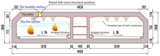
Figure 1.
Cross section of the steel–concrete–steel immersed tube tunnel (unit: cm).
The design thickness of the top plate of the tube structure is 1.5 m, which is a super-thick structure. To meet the fire test conditions of the full-size structural test members, a high-temperature ablation test platform for the structural characteristics of steel–concrete–steel immersed tube tunnels was designed and established by the group. The test principle of the system is shown in Figure 2. Considering the most unfavorable situation, the RABT heating curve was adopted for the fire temperature test curve in the test furnace (Figure 3). The temperature was rapidly raised to about 1200 °C within 5 min, and then it starts to cool down after 120 min. At 225 min, the temperature cooled and the test was stopped. The ambient temperature conditions on the backfire surface were equal to the indoor temperature.

Figure 2.
Schematic of fire test on a structural member. (a) Schematic diagram of the tube structure under fire at the unilateral side; (b) front view of the tube structure under fire at the unilateral side.

Figure 3.
RABT tunnel fire heating curve.
2.2. Test Parameters
The tests mainly studied the fire protection solutions of steel–concrete–steel tube structures under the RABT temperature rise curve, and compared and analyzed the effects of no fire protection, fireproof coatings insulation and fireproof board insulation on the steel–concrete–steel structures. The specific test conditions are shown in Table 1.

Table 1.
Fireproof test conditions of tube structures.
The calcium silicate fireproof boards produced by the same manufacturer were selected for working conditions 3 and 4, with a board size of 1000 mm × 1000 mm (length × width). The joint working condition of fireproof boards was as follows: A whole board of fireproof board was cut into two of the same size along the central line, and caulk construction treatment was at the middle seam. The fireproof boards were laid parallel to the steel shell of the bottom plate directly below the member, and were fixed on the keels with expansion bolts. The high-temperature refractory binder brought by the fireboard manufacturer was adopted for the caulking structure treatment of fireproof board assembly (Figure 4).

Figure 4.
Working condition diagrams of the single-layer seam and the double-layer seam. (a) Working condition diagram of the single-layer seam; (b) working condition diagram of the double-layer seam.
2.3. Temperature Control Criteria for Fire Resistance Limits
The fire resistance requirement for steel–concrete–steel structures in Section 7.3.4 of NFPA 502-2020 is: The surface temperature of steel shell structure does not exceed 300 °C under the RABT heating curve [23].
2.4. Member Production and Fireproof Layer Installation
To reflect the temperature transfer law of the tube structure in a fire more truly, the test members and tunnel tube structure should be consistent in terms of geometric size and structural construction. A cube member was composed of an internal steel shell skeleton and an external concrete element, with the dimensions of 1.0 m × 1.0 m × 1.5 m (L × W × H), and its height was the same as the thickness of the top plate of the tube structure. The internal steel shell structure was composed of a top steel plate, a bottom steel plate, a horizontal partition, a longitudinal partition, T-ribs and horizontal baffles, as shown in Figure 5. Among them, the top and bottom plates were made of Q420B steel with a thickness of 30 mm; the horizontal and longitudinal partitions were made of Q390B steel; the T-ribs and horizontal baffles were made of Q345B steel. The external concrete structure was made of C50 high-strength concrete, and the manufactured members are shown in Figure 6.
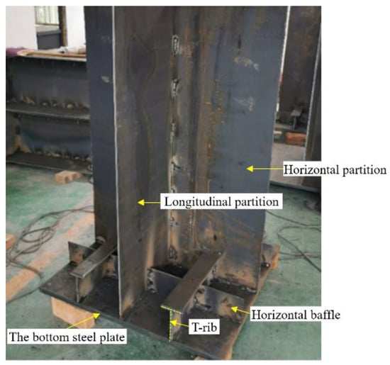
Figure 5.
Construction of the steel shell inside the member.
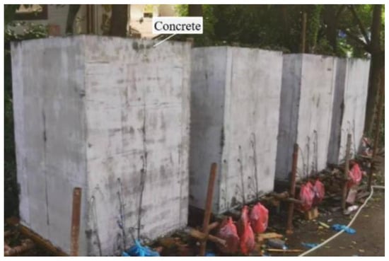
Figure 6.
Manufactured members.
The application of fireproof coating was operated on-site by professional technicians of the coating company. The thermocouples were first laid on the bottom surface of the steel shell, and then the fireproof coating was applied to the bottom surface of the steel shell of the member. The fireproof coating was applied at intervals in layers, with the first coat being 3–4 mm thick and each subsequent coat being 3–5 mm thick. After the second application, the wire mesh was fixed to the surface of the member, the fireproof coating was applied again to the thickness required by the design documents and the final set was moisturized for seven days. Initially, spray maintenance was used, followed by natural maintenance for 21 days. After this, the fireproof coating is formed, as shown in Figure 7a.
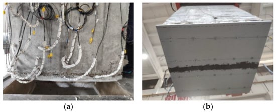
Figure 7.
Complete installation of the fireproof layers. (a) Fireproof coating spraying finished; (b) fireproof board installation completed.
The test procedure for the single-layer seam working condition was as follows: Installation of keels at the bottom of the member—placement of measuring points at the bottom—installation of half of the fireproof board—caulking of the seam position—installation of the other half of the fireproof board—lifting—access of acquisition module—commissioning of the acquisition system—ignition. The method of fireproof boards’ double-layer seam: The upper layer was laid with a whole fireproof board, and the lower layer was the same as the installation process for the single-layer seam fireproof board, to simulate the double fireproof boards staggered seam assembly structure, the installation of fireproof boards is shown in Figure 7b.
2.5. Temperature Measuring Points Layout
- (1)
- Arrangement of temperature measuring points inside the member
A total of 15 K-type armored thermocouples were pre-buried inside the test member. During the test, the thermocouples were connected to the acquisition module and through the converter to the computer for data acquisition once every 3 s. The pre-buried thermocouple positions were as follows: in the horizontal direction, three measurement sections a, b and c were arranged at equal intervals. Section a was along the longitudinal partition of the member, section b was along the T-rib, and section c was along the outer edge of the member, with the section spacing of 250 mm apart (Figure 8a). In the vertical direction, starting from the upper surface of the bottom steel plate, six observation heights were set vertically upward, which were 0 mm, 75 mm, 150 mm, 400 mm and 550 mm from the upper surface of the bottom plate. The highest observation height of the thermocouple at the steel plate was 700 mm and 550 mm for sections a and b, respectively, and the highest observation height of the thermocouple at the concrete was 400 mm for section c, taking into account that the steel has a stronger thermal conductivity than concrete (Figure 8b). The vertical arrangement of thermocouples was used to examine the change and decay law of temperature along the direction of structure thickness, and the horizontal arrangement of thermocouples was used to study the difference of temperature transmission in steel shell and concrete.

Figure 8.
Distribution of thermocouples inside the member (unit: mm). (a) The horizontal position of the measuring points; (b) the longitudinal position of the measuring points.
- (2)
- Arrangement of temperature measuring points in the cavity (between the backfire side of the fireproof boards and the bottom steel plate)
To study the protective effect of the fireproof layers on the tube structure and the influence of the fireproof board’s seam treatment on the steel shell structure, two measurement points, mid-1-bottom and mid-2-bottom, were placed in the middle of the lower surface of the bottom steel plate and were situated directly above the location of the fireproof board’s seam. A measurement point was arranged at 25 cm left and right of the middle-1-bottom, named side-1-bottom and side-2-bottom, respectively. As the fireproof board was indirectly fixed on the surface of the steel shell through the angle steel, there was a certain height of the cavity air layer between the backfire surface of the fireproof board and the bottom steel plate (Figure 9). To study the direction and law of temperature transfer, the measurement points were arranged in the cavity, and the measurement points in the same vertical position were a group. The naming of the measurement points: the bottom position (mid, side)—number (1, 2)—vertical position (bottom, cavity, board). A set of measuring points in the middle, for instance, was given the names mid-1-bottom, mid-1-cavity, and mid-1-board (Figure 10). Different from the installation of fireproof boards, fireproof coatings were directly coated on the bottom surface of the member, so there was no cavity air layer and only the measurement points were arranged at the bottom of the steel shell.
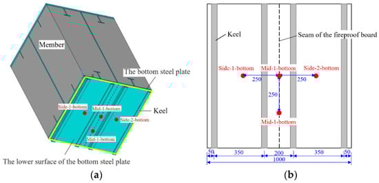
Figure 9.
Position diagram of measuring points at the bottom of steel shell (unit: mm). (a) The lower surface of the bottom steel plate and measuring points position; (b) the specific location of the measuring points.
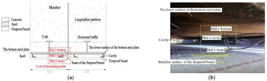
Figure 10.
Diagram of vertical measuring points’ position in the cavity. (a) Diagram of a set of measuring points; (b) the arrangement of a set of measuring points in an experiment.
3. Test Results and Analysis
3.1. Test of No Fire Protection
In the absence of fire protection measures, the temperature of the lower surface of the bottom steel plate reaches 300.6 °C at 69 s, exceeding the test fire resistance limit (300 °C). The test is stopped at 957 s due to safety hazards, by which time the temperature of the bottom steel plate has reached 1037.2 °C. The member shows significant vertical and transverse cracks after the fire. The concrete bursts from the longitudinal partition of the steel shell in the middle of the member, and the vertical crack is 1.5 m long from the top to the bottom of the member (Figure 11a). Transverse cracks appear in the lower part of the member, extending from the edge to the middle of the member, with the height of the cracks at the edge being approximately 450 mm, higher than the transverse cracks in the middle (Figure 11b).

Figure 11.
Cracks in the member without fire protection. (a) Vertical cracks; (b) transverse cracks.
3.2. Thermal Insulation Test for Fireproof Coatings
The time-temperature curves of the measuring points at the bottom in the fireproof coating test are shown in Figure 12. The temperature of the mid-1-bottom shows an inflection point at 474 s, which begins to rise sharply from 23.3 °C and reaches 321.5 °C at 483 s, exceeding the fire resistance limit standard. The temperature of the mid-2-bottom shows an inflection point at 483 s and begins to rise steeply from 24.0 °C. At 510 s, the temperature of the mid-1-bottom is as high as 377.0 °C, and the test is stopped for the protection of the member and the safety of the test. At this time, the temperature of the mid-2-bottom is 280.5 °C. According to the temperature rising trend, if the test continues, the temperature of the mid-2-bottom would exceed 300 °C. Throughout the test, the temperature of the side-1-bottom increases from 23.2 °C to 23.3 °C, the temperature of the side-2-bottom increases from 25.4 °C to 26.6 °C, and there is no obvious temperature change at the two measuring points.
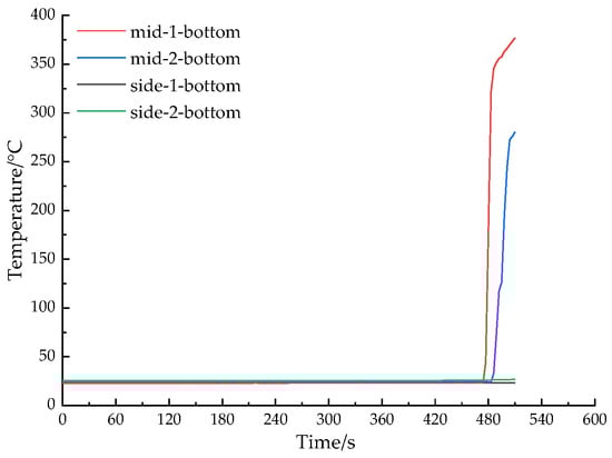
Figure 12.
Time-temperature curves of bottom measuring points in heat insulation test of fireproof coating.
After the temperature of the furnace box had dropped to indoor temperature, the member was lifted out of the furnace, and the fireproof coating was found to be partially detached, as shown in Figure 13. The fireproofing coating had many blocky broken parts on the fire surface, and many cracks were extended around along the broken position. As seen from the direction of the fireproof coating thickness, by the time the test stopped (510 s), the fireproof coating showed obvious delamination, the 30 mm thick fireproof coating did not burn completely, and the fireproof coating was divided into the fireproof coating that was burned and the fireproof coating that did not reach the burning depth after the fire. The place where the fireproof coating was damaged and falling off was the peeling between the fireproof coating that was burned and the fireproof coating which had not reached the burning depth. After that, the flame could enter from the broken parts into the deep layer, making the surface temperature of the bottom steel plate exceed the limit quickly. It may be deduced that the fireproof coating is compromised and comes off during the combustion process, leaving the member without any insulation measures, which causes the temperature at the bottom of the member to rise quickly at a specific period.
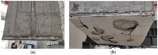
Figure 13.
Diagrams of the first fireproof coating insulation test. (a) The front view of the member after the fireproof coating caught fire; (b) diagram of the fireproof coating damage.
After the test, the producer made improvements to the fireproof coating construction method and coating material, and a second fireproof coating insulation test was conducted (Figure 14a). The test was terminated after the temperature of the side-1-bottom reached 300.1 °C at 2514 s and the temperature of the side-2-bottom surpassed the fire resistance limit at 4761 s. The fire resistance duration of the member was increased compared to the first fireproof coating test, but it still fell short of the test’s fire resistance standards, and the fireproof coating adhering to the steel plate surface of the member fell off in one piece (Figure 14b).
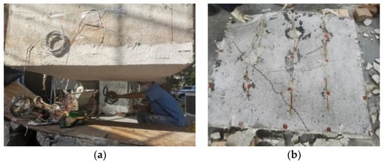
Figure 14.
Diagrams of the second fireproof coating insulation test. (a) Laying diagram of the fireproof coating after improvement; (b) overall shedding of the fireproof coating.
The results of the fireproof coating insulation test show that the fireproof coating insulation scheme is not suitable for steel–concrete–steel structure projects. The main reasons are as follows. (1) Material bonding: The exterior of the steel–concrete–steel tube structure is made of steel which is smoother than concrete. In the early stage of construction, it is easy to lead to insufficient bonding strength between the fireproof coatings and the steel shell. The fireproof coatings will easily break or fall off under the action of an earthquake or repeated vibration induced by vehicles if the bond strength between the fireproof coatings and the steel structure is low. Additionally, the fire resistance properties of steel structures will be significantly reduced after local damage to the fireproof coatings, and then the fire protection function will be partially or completely lost. (2) Construction process: The fireproof coating construction is divided into several different thicknesses of coating, and the wire square mesh is added in the middle layer. Compared to prefabricated fireproof boards, which can be immediately fixed on the surface of the tube structure and do not require maintenance time, fireproof coatings not only have the problem of a complicated construction process, but also require long maintenance time later. (3) Appearance: Compared with fireproof boards, the surface of fireproof coatings is less flat and smooth, which affects the aesthetic appearance of tunnels.
3.3. Thermal Insulation Test for Fireproof Boards
3.3.1. The Maximum Temperature of the Measuring Points at the Bottom Steel Plate
To study the degree of protection of the tube structure by the different fire protection constructions, the surface temperature on the bottom steel plate is analyzed (Figure 15). Under both single-layer and double-layer seam fire protection constructions (referred to as single seam and double seam later), the maximum temperatures of the lower surface of the bottom steel plate do not exceed the specified fire resistance requirement (300 °C). The overall temperature of the measuring points on the surface of the bottom steel plate under the double seam solution is lower than that of the single seam solution, with an average temperature of 61.425 °C lower at each point, indicating that the double seam solution is more effective in protecting the tube structures.
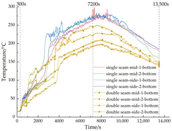
Figure 15.
Time-temperature curves of measuring points on the surface of the bottom steel plate.
3.3.2. Temperature Transfer Pattern in the Cavity
To investigate the effect of different seam constructions on temperature transfer, the authors studied the temperature rise of the measuring points in the cavity under the two working conditions (Table 2, Figure 16). According to the test results of a set of measuring points vertically arranged in the cavity, the temperatures of the fireproof board, the air of the cavity, and the bottom of the members are in ascending order from high to low. From this, it can be judged that the heat in the cavity on the back side of the fireproof boards is transferred along the fireproof boards and the air in the cavity to the bottom of the member. The temperature difference between the measuring points on the backfire surface of the fireproof board and the surface temperature of the bottom steel plate is large, indicating that the fireproof boards have an obvious fire insulation effect. The average temperature differences between the measuring points are 133.27 °C and 458.37 °C under the single-seam and double-seam schemes, respectively. In comparison, the fireproof boards with double-layer seam construction are more effective in insulating the hot flue gas transmitted to the bottom steel plate and provide better protection for tube structures. Traditional reinforced concrete tunnels are installed with fireproof boards or fireproof coatings directly on the lining surface, and heat is transferred directly to the interior of the tube structure through the fireproof layers. While the fireproof board installation of steel–concrete–steel structure tunnels is the fireproof board indirectly fixed in the tube structure below through the expansion screws, which makes the backfire surface of the fireproof boards reserved for a certain height of air layer. Since the thermal conductivity of air is much lower than that of steel, this method of indirect installation of fireproofing can effectively slow down the transfer of temperature and provide better protection.
Table 2.
Maximum temperature of the measuring points in the cavity behind the fireproof board.
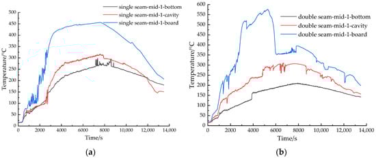
Figure 16.
Time-temperature curves of the measuring points in the cavity. (a) Condition of the single seam; (b) condition of the double seam.
For the measuring points’ temperatures on the backfire surface of the fireproof boards, the temperature of the mid-1-board is higher than that of the side-1-board and the side-2-board in single-layer seam condition. While the law of double-layer seam working condition is on the contrary, that the temperature of the mid-1-board is lower than that of the side-1-board and side-2-board. The position of the seams is a weak link if the fireproof board adopts the single-layer seam construction. The thermal conductivity of the high-temperature fire-resistant binder is higher than that of the fireproof boards, or if the caulking is not properly handled, the heat will pass directly through the high-temperature fire-resistant binder into the air in the cavity, and then directly to the tube structure, causing damage to the tube structure. Additionally, for the fireproof boards of double-layer seam construction, the heat is transferred to the upper layer of the fireproof board through the high-temperature fire-resistant binder. Compared to the single-layer seam construction, the upper fireproof board of the double-layer fireproof boards can play a secondary role in blocking the hot flue gas when the high-temperature refractory binder fails, reducing the damage caused by the hot flue gas to the tube structure.
Analysis of all temperature measuring points in the cavity shows that the temperature differences between the measuring points of the mid-1-board, side-1-board, and side-2-board are 120.2 °C, 358.7 °C, and 320.4 °C; the temperature difference of the mid-1-cavity is 6.5 °C; the temperature differences of the mid-1-bottom, mid-2-bottom, side-1-bottom, and side-2-bottom are 67.3 °C, 69.7 °C, 76.4 °C, and 32.3 °C under two working conditions. It is not difficult to find that the temperatures of the measuring points on the backfire surface of the fireproof boards with double-layer seam are higher than those on the single-layer seam condition, but the temperatures inside the cavity and on the surface of the bottom steel plate are lower than those on the single-layer seam condition, and the maximum temperature difference on the backfire surface of the fireproof board has reached 358.7 °C. To investigate this phenomenon, the temperature rise law of the measuring points in the cavity under the double-layer seam scheme was analyzed. Under the double seam scheme (Figure 16b), the temperature on the backfire side of the fireproof boards showed a sharp rise to a peak and then a sudden drop, which does not occur in the single seam scheme. The analysis is because the expansion high-temperature refractory binder used in the seam of the lower layer fireproof board has certain construction defects. At the beginning of the fire, the high-temperature refractory binder has not yet taken effect, and the temperature of the backfire surface of the fireproof board soars. Subsequently, under the action of high temperature, the high-temperature binder is heated and expanded, forming a porous heat insulation layer, which improves the heat insulation effect of the fireproof boards. After this, there is a sudden drop in temperature. This confirms that the upper fireproof board in the double-layer seam construction can effectively act as a secondary barrier to hot smoke in the presence of construction defects in the caulking treatment. However, the measuring points on both sides of the seam on the backfire surface of the fireproof board are higher than the measuring points at the seam. It may be due to the construction method of the double seam so that there is a gap between the two layers of the fireproof boards in the initial test. Alternatively, the deformation of the fireproof boards after encountering heat, the hot smoke enters from the side seam of the two fireproof boards, resulting in the temperature soaring at the measuring points on both sides of the seam on the backfire surface of the fireproof boards.
To sum up, from the two aspects of the air layer behind the fireproof boards can slow down the temperature transmission and the upper fireproof board of double-layer seam construction can secondarily obstruct the hot smoke in the case of high-temperature refractory binder failure, the fireproof boards using the “upper whole board + lower joint board” (double-layer fireproof boards staggered joint in practical engineering) can effectively block the hot smoke and reduce the damage of hot smoke to the tube structure in the fire.
3.3.3. Depth of Fire Impact
The temperature rise of each section is shown in Figure 17 and Figure 18 under the protection of single-seam and double-seam fireproof boards, excluding the thermocouples damaged during the test. The temperature rise trend of each section is the same under the two conditions, but the overall temperature of the measuring points of the double seam is lower than that of the single seam solution, indicating that the staggered assembly scheme of double seam fireproof boards has a better protection effect on tube structure.

Figure 17.
Temperature values of measuring points at each section under single-layer seam construction. (a) Section a; (b) Section b; (c) Section c.
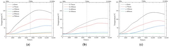
Figure 18.
Temperature values of measuring points at each section under double-layer seam construction. (a) Section a; (b) Section b; (c) Section c.
The temperature of each section in the member with the temperature change of the furnace shows a certain regularity, but the two are not synchronized. The temperature of the measuring points in the member rises and falls at a rate smaller than the rate of temperature change in the furnace. In the furnace heating (0~300 s) and constant temperature stage (300~7200 s), the temperature of measuring points increases with the temperature inside the furnace; while in the furnace cooling stage (7200~13,500 s), the temperature of measuring points at the height of 0 mm, 75 mm and 150 mm from the upper surface of the base plate continues to increase until it reaches the maximum temperature, then it slowly decreases and the time to reach the maximum temperature is successive. The time to reach the highest temperature is the height measuring point of 0 mm, 75 mm, and 150 mm from the upper surface of the bottom plate successively. The temperature at the higher measuring points (400 mm and above) continues to rise with no obvious downward trend. This is because the temperature of the lower measuring points is always higher than the temperature of the higher measuring points, and the temperature difference gradually increases, so that the heat continues to be transferred from the lower measuring points to the higher measuring points, making the higher measuring points continue to be in the warming stage. While the temperature of the measuring points that has not reached the depths of heat transfer is almost no great fluctuation and change throughout. Under the two conditions, as can be seen in sections a and b, the depth of fire impact in the member can reach approximately 550 mm from the upper surface of the bottom steel plate. Section c is a concrete section, the overall temperature is lower than in sections a and b, and the height of heat transfer is approximately 400 mm. Steel has a greater depth of temperature transfer than concrete, more heat is transferred and the rate of heat transfer is faster.
4. Numerical Simulation Analysis
ANSYS, a large general finite element analysis software, is used for numerical simulation. Additionally, SOLID70, a three-dimensional solid thermal unit, is selected as the heat transfer unit. The finite element transient thermal analysis method is used to analyze the influence of high fire temperature (RABT standard temperature rise curve) on the tube structure of the steel–concrete–steel immersed tube tunnel, the temperature distribution rule and the heat insulation effect of fireproof materials in the tube structure of the steel–concrete–steel immersed tube tunnel under different fire prevention technologies. The contact surface between the steel and fireproof coating layer does not consider the influence of thermal resistance.
The main assumptions made in the numerical simulation are as follows: (1) The steel shell skeleton is made of different materials at different locations within the tube structure, the steel shell is considered to be of the same type in the simulation and is considered to be a homogeneous material with the same parameters (thermal conductivity, etc.); (2) the RABT standard heating curve is implemented in the form of a finite element loading curve and is applied to the surface of the tube structure, assuming that the surface of the tube structure is uniformly subjected to fire; and (3) the effect of using a high-temperature refractory binder for caulking the fireproof seam is ignored in the simulation, and the heat transfer of the expansion screws is not considered.
To facilitate the study and make the conclusions comparative, temperature measuring points at the same locations as the test members are also taken for the numerical simulation.
4.1. Thermal Boundaries and Initial Conditions
In an actual fire, the back of the immersed tunnel structure (the upper surface of the tube structure) is surrounded by backfill. Due to the oversized thickness of the structure (1.5 m), the temperature at the back interface is generally low, with little temperature difference from the backfill, and close to ambient temperature [18]. Additionally, the initial temperature is taken as 20 °C. The bottom surface of the steel–concrete–steel tube structure is the fire surface and the heating curve follows the standard RABT heating curve. Heat transfer mainly includes heat conduction, heat convection, and heat radiation. During the fire, heat transfer between the hot air and the fire surface (fireproof boards, fireproof coatings, tube structure surface) is mainly through heat convection and heat radiation. While heat transfer inside the fireproof layer and between the fireproof layer and the steel plate is mainly through heat conduction.
4.2. Thermal Parameters
The thermal parameters of the material determine the temperature distribution inside the lining structure [24]. Densities of the structural steel and concrete can be taken as a constant: ρS = 7850 kg∙m−3; ρC = 2300 kg∙m−3.
4.2.1. Thermal Parameters of Steel
- (1)
- Thermal conductivity of steel shell λS [25]
- (2)
- Specific heat capacity of steel shell CS [25]where: λS—the thermal conductivity of steel (W·m−1·K−1); CS—the specific heat of steel (J·kg−1·K−1).
- (3)
- Convection heat transfer coefficient of steel
Without fire protection, the convective heat transfer coefficient between the hot flue gas stream and the steel shell surface is taken as 30 W·m−2·K−1.
4.2.2. Thermal Parameters of Concrete
- (1)
- The thermal conductivity of concrete λc [26]:
- (2)
- The specific heat capacity of concrete CC [26]:where: λC—the thermal conductivity of concrete (W·m−1·K−1); CC—the specific heat of concrete (J·kg−1·K−1).
4.2.3. Thermal Parameters of Fire Protection Layers
According to the product characteristics, the values of thermal parameters of fireproof coating and single-layer fireproof board are shown in Table 3. The combined thermal radiation coefficient between the external surface of the fireproof layers and the environment is taken as 0.8.
Table 3.
Values of Thermal Parameters of Fireproof Layers.
4.2.4. Thermal Parameters of Air
The thickness of the air layer on the backfire side of the fireproof board is small and only the form of heat transfer is considered. Assuming that the pressure inside the cavity is maintained at atmospheric pressure, the heat loss due to gas escape is neglected. p = 1.013251 × 10⁵ Pa, the air density, specific heat capacity, and thermal conductivity change with temperature are shown in Figure 19.

Figure 19.
Curves of air density, specific heat capacity, and thermal conductivity.
4.3. Computational Simulation Analysis
4.3.1. No Fire Protection Measures
When no insulation is provided (no fireproof coatings and fireproof boards), the fire is simulated numerically for the test member and the analysis process does not take into account the effect of concrete bursting. In the simulation, the temperature at the bottom of the steel shell reaches 291.4 °C at 69 s and 303.2 °C at 72 s (over 300 °C), as shown in Figure 20, while the temperature at the lower surface of the bottom steel plate is 300.6 °C when the test is conducted up to 69 s. The results of numerical simulation are in good agreement with the experimental results.

Figure 20.
Forward contour plot of the member at 72 s.
The calculation results of temperature distribution in the tube structure of the test member at 7200 s (120 min) and 13,500 s (when the test stops) are shown in Figure 21. From the figures, it can be seen that: (1) The depth of temperature transfer in the tube structure increases gradually with time. Until the test stops, the maximum depth of fire impact is reached; (2) there is a significant temperature gradient within the member, with the temperature increasing closer to the bottom steel plate; (3) the thermal boundary is uniformly exposed to fire, due to the symmetry of the structure of the member, the temperature distribution is symmetrical along the central longitudinal partition axis. The temperature distribution at the steel shows a convex shape: The depth of temperature influence is greatest at the central steel plate, followed by the T-rib, and lowest at the concrete on both sides; (4) as can be seen from Figure 21a, the temperature distribution fluctuates significantly closer to the steel structure, with a significant temperature ‘spike’ at the steel. This means that the steel temperature is greater than the concrete temperature at the same horizontal depth; and (5) as can be seen from Figure 21b, there is a residual temperature inside the member when the test stops, with a maximum value of 442.31 °C, distributed on both sides of the T-rib.

Figure 21.
Forward contour plot of the member. (a) At 7200 s; (b) At 13,500 s.
The time-temperature curves of the measuring points at sections a and c inside the member are shown in Figure 22. From the figure, it can be seen that: (1) Without insulation measures, the depth of influence of fire at the steel plate is 700 mm, the depth of influence of fire at the concrete is 550 mm, and the corresponding measuring point temperatures rise from 20 °C to 26.23 °C and 24.14 °C respectively. Additionally, the temperature of the structure above the depth of influence remains at indoor temperature; (2) the heat transfer rate of the steel shell is fast, and the temperature of the lower surface of the bottom steel plate (mid-1-bottom) and the upper surface (a-0mm, c-0mm) are close to each other. The maximum temperatures of a-0mm and c-0mm are 1155.28 °C and 1184.00 °C, respectively, which are 44.72 °C and 16 °C different from the bottom steel plate surface.; (3) the steel plate has a faster heat transfer rate than the concrete, observing the measuring points of the same height temperature, it can be seen that the temperature of the a-0mm and a-75mm is much greater than that of c-0mm, c-75mm at the same time, respectively. The temperature of a-0mm and c-0mm reaches the maximum temperature before that of c-0mm and c-75mm.
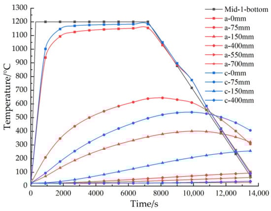
Figure 22.
Time-temperature curves of each measuring point in the member without fire prevention measures.
4.3.2. Fire Protection Layer Insulation
- (1)
- Fireproof coating insulation
Under the protection of fireproof coatings, the depth of fire effect is 550 mm for steel plates and 400 mm for concrete, with a-550mm and c-400mm rising from 20 °C to 25.81 °C and 23.68 °C respectively (Figure 23). The reduced depth of fire temperature impact compared to that of the members without insulation indicates that fireproof coatings have a significant effect on the fire protection of the tube structure. However, the maximum surface temperature of the bottom steel plate is 322.45 °C (Figure 24), which exceeds the fire resistance limit temperature criteria.
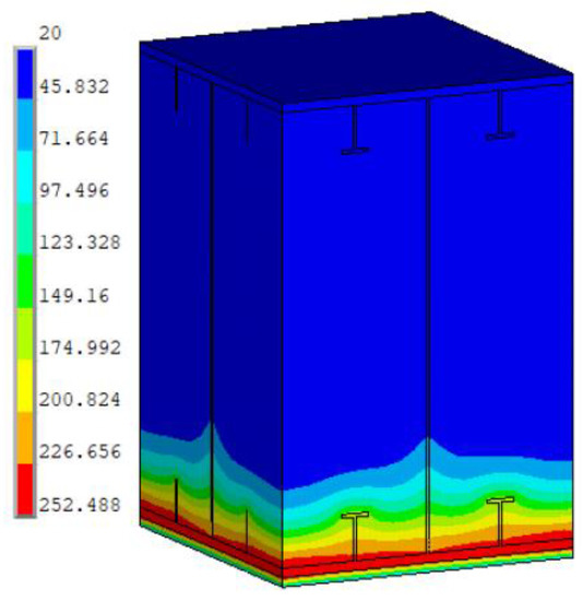
Figure 23.
Forward contour plot of the member under the protection of fireproof coating at 13,500 s.
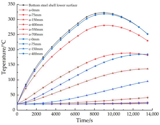
Figure 24.
Time-temperature curves of each measuring point in the member under the protection of fireproof coating.
- (2)
- Fireproof board insulation
Under the protection of fireproof boards, the depth of fire effect is 550 mm for steel plates and 400 mm for concrete, with a-550mm and c-400mm rising from 20 °C to 24.04 °C and 21.97 °C respectively (Figure 25). The reduced depth of fire temperature effect on the members compared to the case without fire protection indicates that fireproof boards have a significant effect on the fire protection of the tube structure. Compared to the fireproof coating insulation, the temperature at the same measuring points is lower, so the fireproof board has a better thermal insulation effect than the fireproof coating. The time-temperature curves of the measuring points at sections a and c inside the member under the fireproof board are shown in Figure 26, which matches the results in Figure 17. The maximum temperature of the lower surface of the bottom steel plate is 264.59 °C, which meets the specified fire resistance requirements.
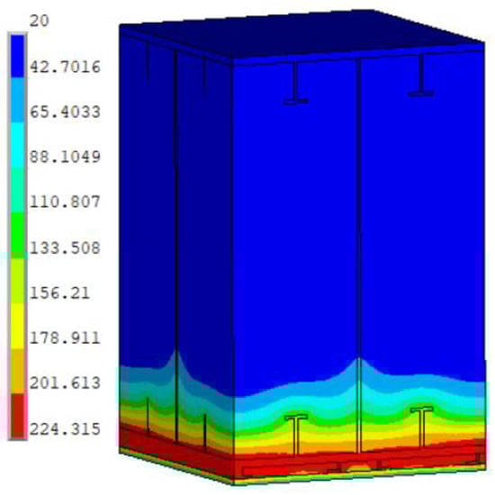
Figure 25.
Forward contour plot of the member under the protection of fireproof board at 13,500 s.
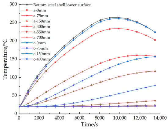
Figure 26.
Time-temperature curves of each measuring point in the member under the protection of fireproof board.
Figure 27 shows the measuring temperatures at the lower surface of the bottom steel plate with and without fire protection. It can be seen from the figure that after applying 30 mm fireproof coating and 25 mm fireproof board to the bottom of the steel shell of the tube structure, the temperature at the surface of the structure under fire is significantly reduced compared to that without fire protection. While laying fireproof board is reduced compared to that with fireproof coating. The maximum temperature reduces from 1200 °C to 322.45 °C and 264.59 °C on the surface of the bottom steel plate of the tube structure with no residual temperature in the members. The installation of the fireproof layer effectively isolates the contact between the high-temperature hot air flow of the fire and the tube structure, reducing the effect of the high temperature of the fire on the internal temperature of the tube structure of the immersed tube tunnel, with significant thermal insulation and cooling effect.

Figure 27.
The temperature of measuring points on the bottom steel plate surface with and without fire protection.
5. Conclusions
- (1)
- As time increased, the depth of temperature transfer within the tube structure gradually increased until the end of the test, when the maximum depth of fire effect is reached. Without fire protection, the depth of fire impact at the steel plate and concrete reaches 700 mm and 550 mm, respectively, while with fireproof coating and fireproof board insulation, the depth of fire impact is reduced to 550 mm at the steel plate and 400 mm at the concrete.
- (2)
- The protection of the tube structure is obviously impacted by the fireproof layers. The bottom steel plate’s surface temperature dramatically decreased after taking fire safety precautions. According to the numerical simulation results, after applying fireproof coating and fireproof board insulation, the maximum surface temperature of the bottom steel plate is lowered from 1200 °C to 322.45 °C and 264.59 °C compared to when no fireproof measures are used. During combustion, the fireproof costings crack and peel off, failing to meet the fire resistance limit standard.
- (3)
- Without fire protection, the members experience concrete bursts, and there are obvious transverse and vertical cracks. During combustion, the fireproof costings crack and peel off, failing to meet the fire resistance limit standard. The single-seam and double-seam construction fireproof board protection, are to meet the specified fire resistance requirements.
- (4)
- The heat in the cavity of the backfire side of the fireproof board is transferred along the fireproof boards and the air of the cavity to the bottom of the member. The difference in temperature between the measuring points on the backfire side of the fireproof boards and the surface temperature of the bottom steel plate is large. The average temperature difference between the measuring points is 133.27 °C and 458.37 °C for the single-seam and double-seam solutions respectively. The double-layer seam fireproof boards have a better heat insulation effect on the hot flue gas transmitted to the bottom of the steel shell and a better protective effect on the tube structure.
Based on the results of the tests, the following enlightenments and suggestions have been made for the structural fire prevention design of steel–concrete–steel immersed tube tunnel sections.
- (1)
- There are issues with a very big-span steel–concrete–steel immersed tube tunnel, including moisture in the cavern, frequent vibration from cars, a complex environment, etc. It is advised to apply fireproof coatings cautiously in such significant projects after a thorough assessment of the fire prevention effect, material bonding, construction process, look, etc.
- (2)
- The thermal conductivity of air is much lower than that of steel. Compared to traditional reinforced concrete tunnels where fireproof boards or fireproof coatings are laid directly on the lining surface and heat is transferred directly through the fireproof layer to the interior of the tube structure, the backfire surface of the fireproof boards can be reserved for a certain height of air layer, which can effectively slow down the temperature transfer and provide better protection.
- (3)
- The location of the fireproof board seams is a weak point in construction. To prevent hot smoke from escaping, the seams should be caulked well and construction defects should be avoided.
- (4)
- Considering the maximum temperature of the steel shell surface of the tube structure, the overall temperature of each section within the structure, and the temperature difference between the backfire surface of the fireproof boards and the surface of the bottom steel plate, the double-layer fireproof boards staggered assembly solution is more effective in protecting the tube structure than the single-layer seam solution, and it is recommended to adopt this fireproof technology solution.
Due to the particularity of the fire test, some measuring points were damaged in the middle of the tests, which could not be repaired or replaced, resulting in incomplete data. To make the data more reliable, more sets of parallel tests will be conducted in the future, and more complex conditions will be further studied in combination with numerical simulation.
Author Contributions
Conceptualization, P.C. and S.J.; methodology, J.L., P.C. and D.Z.; software, J.L. and P.C.; validation, J.L. and D.Z.; formal analysis, J.L. and P.C.; investigation, J.L., P.C. and D.Z.; resources, P.C. and S.J.; data curation, J.L. and D.Z.; writing—original draft preparation, J.L. and D.Z.; writing—review and editing, P.C. and S.J.; visualization, J.L. and D.Z.; supervision, P.C. and S.J; project administration, P.C. and S.J; funding acquisition, P.C. and S.J. All authors have read and agreed to the published version of the manuscript.
Funding
This study was funded by the National Key R&D Program of China (no. 2021YFC3002000), the National Natural Science Foundation of China (no. 52127814), the Chongqing Natural Science Foundation (no. cstc2021jcyj-msxmX0591).
Data Availability Statement
Data available on request.
Conflicts of Interest
The authors declare no conflict of interest.
References
- Yan, J.B.; Zhang, W. Numerical analysis on steel-concrete-steel sandwich plates by damage plasticity model: From materials to structures. Constr. Build. Mater. 2017, 149, 801–815. [Google Scholar] [CrossRef]
- Huang, Z.Y.; Liew, J.Y. Steel-Concrete-Steel Sandwich Composite Structures Subjected to Extreme Loads. Int. J. Steel Struct. 2016, 16, 1009–1028. [Google Scholar] [CrossRef]
- Kim, S.; Shim, J.; Rhee, J.Y.; Jung, D.; Park, C. Temperature Distribution Characteristics of Concrete during Fire Occurrence in a Tunnel. Appl. Sci. 2019, 9, 4740. [Google Scholar] [CrossRef]
- Kumar, W.; Sharma, U.K.; Shome, M. Mechanical properties of conventional structural steel and fire-resistant steel at elevated temperatures. J. Constr. Steel Res. 2021, 181, 106615. [Google Scholar] [CrossRef]
- Lucherini, A.; Maluk, C. Intumescent coatings used for the fire-safe design of steel structures: A review. J. Constr. Steel Res. 2019, 162, 105712. [Google Scholar] [CrossRef]
- Wang, W.; Liu, T.; Liu, J. Experimental study on post-fire mechanical properties of high strength Q460 steel. J. Constr. Steel Res. 2015, 114, 100–109. [Google Scholar] [CrossRef]
- Du, S.; Zhang, Y.; Sun, Q.; Gong, W.; Geng, J.; Zhang, K. Experimental study on color change and compression strength of concrete tunnel lining in a fire. Tunn. Undergr. Space Technol. Inc. Trenchless Technol. Res. 2018, 71, 106–114. [Google Scholar] [CrossRef]
- Wang, F.; Wang, Y.; Huang, Y.; Yan, Q. Experimental study on the smoke temperature distribution alongside the lining in tunnel fires. Therm. Sci. 2019, 23, 3701–3710. [Google Scholar] [CrossRef]
- Yan, Z.G.; Zhu, H.H.; Ju, J.W. Behavior of reinforced concrete and steel fiber reinforced concrete shield TBM tunnel linings exposed to high temperatures. Constr. Build. Mater. 2013, 38, 610–618. [Google Scholar] [CrossRef]
- Jiang, S.P.; Zhang, E.Q.; Guo, J.; Liu, S.; Zhang, Z.Y. Experimental study of the fire-resistance of structural elements of immersed tunnels. Mod. Tunn. Technol. 2014, 51, 43–49. [Google Scholar] [CrossRef]
- Wang, F.; Wang, M.N.; Huo, J.X. The effects of the passive fire protection layer on the behavior of concrete tunnel linings: A field fire testing study. Tunn. Undergr. Space Technol. Inc. Trenchless Technol. Res. 2017, 69, 162–170. [Google Scholar] [CrossRef]
- Duan, J.T.; Dong, Y.L.; Xiao, J.Z.; Zhang, D.S.; Zheng, W.; Zhang, S.Y. A large-scale fire test of an immersed tunnel under the protection of fire resistive coating. Tunn. Undergr. Space Technol. Inc. Trenchless Technol. Res. 2021, 111, 103844. [Google Scholar] [CrossRef]
- Lin, J.Q.; Dong, Y.L.; Duan, J.T.; Zhang, D.S.; Zheng, W. Experiment on single-tunnel fire in concrete immersed tunnels. Tunn. Undergr. Space Technol. Inc. Trenchless Technol. Res. 2021, 116, 104059. [Google Scholar] [CrossRef]
- Xi, Y.; Wu, M.J.; Cao, P.; Chen, J.Z.; Chen, J.T. Temperature distribution of a composite structure with steel-shell and concrete under high temperature of fire. Chin. J. Undergr. Space Eng. 2020, 16, 985–992. [Google Scholar]
- Cao, P.; Wu, M.J.; Xi, Y.; Deng, X.H.; Chen, J.Z. Study on the temperature transfer rule of the steel-concrete-steel composite structure subjected to fire. Chin. J. Undergr. Space Eng. 2020, 16, 323–328. [Google Scholar]
- Wang, W.; Yao, X.; Gao, G.; Zhang, Y. Study on Roof Deterioration Characteristics of Immersed Tunnel Exposed to Fire by Multi-Phase Meso-Model. Int. J. Concr. Struct. Mater. 2022, 16, 14. [Google Scholar] [CrossRef]
- Wang, W.; Li, D. Thermal-mechanical coupling analysis and fire protection experiment on immersed tunnel exposed to fire. J. Saf. Sci. Technol. 2015, 11, 17–22. [Google Scholar] [CrossRef]
- Guo, J.; Liu, S.; Jiang, S.P. Fire-proof test and numerical simulation on tube structure of subsea tunnel. China J. Highw. Transp. 2016, 29, 96–104+114. [Google Scholar] [CrossRef]
- Guo, J.; Jiang, S.P.; Zhang, Z.Y. Fire Thermal Stress and its Damage to Subsea Immersed Tunnel. Procedia Eng. 2016, 166, 296–306. [Google Scholar] [CrossRef]
- Cao, P.; Hu, X.B.; Liu, E.L.; Chen, J.Z.; Jiang, S.C.; Ding, H. Research on Mechanical Behavior of the Steel–Concrete–Steel Composite Structures Subjected to High Temperature of Fire. Materials 2022, 15, 4872. [Google Scholar] [CrossRef]
- Alhawat, H.; Hamid, R.; Baharom, S.; Azmi, M.R.; Kaish, A.B.M.A. Thermal behavior of unloaded concrete tunnel lining through an innovative large-scale tunnel fire experimental testing setup. Constr. Build. Mater. 2021, 283, 122718. [Google Scholar] [CrossRef]
- JTG B01-2014; Technical Standard of Highway Engineering. China Communications Press: Beijing, China, 2014.
- NFPA 502-2020; Standard for Road Tunnels, Bridges, and Other Limited Access Highways. National Fire Protection Association: Quincy, MA, USA, 2019.
- Saito, S.; Yamauchi, Y. Numerical study of the influence of tunnel wall properties on ceiling jet temperature in tunnel fires. Tunn. Undergr. Space Technol. 2021, 116, 104087. [Google Scholar] [CrossRef]
- ENV 1993-1-2; Eurocode 3 Design of Steel Structures (Partl/2), General Rules-Structural Fire Design. British Standards Institution: London, UK, 2005; pp. 3–14.
- Nordmark, A. Fire and life safety for underground facilities: Present status of fire and life safety principles related to underground facilities: ITA working group 4, “subsurface planning”. Tunn. Undergr. Space Technol. 1998, 13, 217–269. [Google Scholar] [CrossRef]


Disclaimer/Publisher’s Note: The statements, opinions and data contained in all publications are solely those of the individual author(s) and contributor(s) and not of MDPI and/or the editor(s). MDPI and/or the editor(s) disclaim responsibility for any injury to people or property resulting from any ideas, methods, instructions or products referred to in the content. |
© 2022 by the authors. Licensee MDPI, Basel, Switzerland. This article is an open access article distributed under the terms and conditions of the Creative Commons Attribution (CC BY) license (https://creativecommons.org/licenses/by/4.0/).