Abstract
Despite the continuous improvement in the research and development of concrete precast composite slab technology, problems like easy cracks and excessive weight at the joints remain. In this study, high-titanium heavy slag was mixed with different kinds of ceramsite to prepare ceramsite lightweight high-titanium heavy slag concrete. The joint of the composite slab was optimized to develop a novel ceramsite lightweight high-titanium heavy slag concrete precast composite slab, hereinafter referred to as “CLHCPCS”. Two CLHCPCS and one ordinary concrete composite slab were prepared. This study analyzed the effects of new materials and improved joints on the flexural capacity and crack resistance of CLHCPCS. It concluded that the density of high-titanium heavy slag concrete with shale ceramsite decreased by 12.0%, and the density of high-titanium heavy slag concrete with fly ash ceramsite decreased by 10.6%. At a 30% dosage of fly ash ceramsite, the compressive strength and splitting tensile strength of concrete reached the maximum. At a 20% dosage of shale ceramsite, the mechanical properties were optimal. Finally, fly ash ceramsite was selected as part coarse aggregate of CLHCPCS. CLHCPCS 1 and 2 demonstrated superior ultimate bearing capacity and crack resistance than ordinary concrete composite slab DBS1, with its ultimate bending capacity test value higher than the average value of ordinary concrete composite slab. ANSYS established the joint model of CLHCPCS for a bending simulation test. The stress and strain distribution of the model and the ultimate bending capacity under the plastic line method were obtained, consistent with theory and experimental analysis results.
1. Introduction
Precast construction utilized industrial production to produce building components and parts in the factory, transport them to the site, and combine and install them using mechanization and information engineering technology [1]. As a key focus in industrialized development of the construction field to practice green, low-carbon development, it has become a research focus worldwide [2]. The research and development of PC precast components is the basis for the development of precast buildings. Precast buildings have the advantages of fast construction speed, high utilization of resources, good mechanical performance [3], reduced environmental pollution and lower incidence of safety accidents [4]. Compared with traditional cast-in-place components, precast components can save natural resources and reduce labour in the production process, with high dimensional accuracy in factorized and standardized production processes [5,6]. As an essential component of precast buildings, the composite slab can bear post-cast concrete load [7], and combine the advantages of cast-in-place structure and precast structure to render excellent performance and high construction efficiency. However, the composite slab has disadvantages such as large dimensions, heavy weight, inconvenient hoisting and transportation, which increases engineering risk [8]. The composite slab has simple joint demanding secondary construction. In this study, high-titanium heavy slag and different kinds of ceramsite were used as coarse aggregate of concrete to reduce the material weight and improve the joint form.
Regarding concrete materials, the use of industrial waste to replace the natural gravel, sand and other admixtures in ordinary concrete is an important embodiment of the construction industry’s green and low-carbon development concept. Hao [9] mentioned that many industrial wastes, including fly ash, coal gangue, and slag, have been used in building blocks, cement, lightweight aggregate concrete, roadbed cushions, Glass-ceramics and other materials. Akinmusuru [10] tested steel slag produced in the Nigerian steel industry and found that its crushing value met the concrete aggregate requirements. Alexander [11] believed that concrete made with low-expansion steel slag aggregate exhibited better fracture performance than dolomite aggregate, demonstrating desirable free/thaw durability. Mohammed [12] used sheet glass waste as aggregate to replace natural gravel to prepare concrete and tested the cube strength of concrete at 1–28 days of age. The results show that waste glass can be used as aggregate of concrete, and its water absorption is lower than that of natural gravel. Jiang [13] used waste glass powder as ordinary Portland cement (OPC) supplementary material and tested the physical and mechanical indexes such as workability, setting time and compressive strength of the prepared paste specimens. The waste glass powder improved the workability of ordinary Portland cement paste and prolonged the setting time. At the same time, degradation of the OPC matrix under high temperatures and could reduce the alkaline aggregate reaction effect. It indicated that waste glass powder auxiliary cementitious materials could improve the safety of OPC-based structures at room temperature and high temperatures.
The high titanium heavy slag concrete was prepared by using high titanium heavy slag as coarse and fine aggregate and grinding admixture, which is an industrial waste from smelting vanadium titano-magnetite in Pangang Group Company Limited, the formation of high titanium heavy slag concrete components, is an important part of the development of slag concrete applications. Currently, a large number of blast furnace slag is accumulated, which not only occupies a large amount of land, but also brings secondary disasters to the ecological environment. At present, research on the resource utilization of slag is being carried out at home and abroad. It is one of the most important ways to use it as a building material in civil engineering. Studies [14,15] have shown that the structural stability, crushing performance, durability and radioactivity of high titanium heavy slag meet the requirements of relevant specifications. High titanium heavy slag concrete is prepared by replacing natural gravel and sand with high titanium heavy slag graded crushing as coarse and fine aggregate and grinding admixture to replace part of the cement. Compared with ordinary Portland cement concrete, it has the advantages of low carbon, green, environmental protection, and low construction cost. Related research is exemplified as follows. Sun [16] studied the application of various mechanical indexes in high-titanium heavy slag concrete, evidenced that high-titanium heavy slag concrete had superior mechanical properties than ordinary concrete. Research on the bond strength between high-titanium heavy slag concrete and reinforcement showed that high-titanium heavy slag concrete could better bond to reinforcement than ordinary reinforced concrete [17]. Zhou used high-titanium heavy slag aggregate as coarse concrete aggregate to conduct experimental research, finding that its splitting and compressive strengths were slightly higher than ordinary concrete [18]. Li used high-titanium heavy slag as the coarse aggregate of high-strength concrete in experimental research, finding that high-strength concrete columns with high-titanium heavy slag aggregate had a comparable anti-seismic performance with high-strength concrete columns with ordinary aggregate [19]. Chen mixed fly ash into high-titanium heavy slag concrete and found that this kind of high-titanium heavy slag concrete had a high collapsibility, which proved the pump-ability of high-titanium heavy slag concrete [20]. Concrete beams were prepared with high-titanium heavy slag concrete. The normal section test of high-titanium heavy slag concrete beams found [21] that the joints of high-titanium heavy slag concrete beams had high ductility, good energy dissipation capacity, and full hysteresis curve, and superior bending strength compared to ordinary reinforced concrete [22]. In the research of new material plate components, Yousuf carried out nonlinear dynamics research on the flexural stiffness of composite slabs [23]. Belardi et al. studied the elasticity of anisotropic composite slabs under in-plane bending and torque [24]. Arasan et al. used a simple model for quickly calculating the dynamic equivalent parameters of three-layer sandwich slabs to calculate the equivalent dynamic response [25]. With the rapid development of precast structures, it is inevitable to use industrial solid waste materials as building materials in building structures.
Engineering practice shows that lightweight aggregate concrete has many advantages over traditional concrete, and will be used in more construction projects [26,27]. In terms of the performance research on weight reduction of concrete with ceramsite materials, Wan [28] added nano-SiO2 to shale ceramsite concrete and fly ash ceramsite concrete. The study found that it could significantly improve the strength of ceramsite concrete and reduce early cracking, but would not significantly increase the long-term shrinkage deformation of concrete. Qiu [29] found that a greater substitution rate of coal gangue ceramsite could effectively improve concrete’s micro pore structure characteristics. Sun [30] tested the compressive strength of concrete using shale ceramsite s of three shapes, finding that concrete test block prepared by spherical shale ceramsite had the largest compressive strength. Yang [31] prepared ceramsite concrete through pre-wetting treatment and shell-building treatment, finding that pre-wetting treatment would improve the workability of the mixture. Huang [32] changed the particle size and curing time of gravel-type shale ceramsite, finding that shale ceramsite concrete had lightweight and good durability. Yu [33] prepared a new type of ceramsite concrete for research by mixing ceramsite and straw fiber. The research showed that this kind of ceramsite concrete had good water retention and lightweight properties and could be used as a protective layer of thermal insulation. Tian [34] studied a new ultra-long interior wall panel type by mixing ceramsite. The study showed that ceramsite concrete had high strength in the early stage, and its thermal conductivity was much lower compared to ordinary concrete. Yang [35] found that adding glass fibre, fly ash and silica powder could effectively optimize the water absorption of concrete. Li [36] added a fixed percentage of shale ceramsite and other mineral admixtures to high-titanium heavy slag concrete, finding that the weight of this composite slab was 658.05 kg lower than that of ordinary concrete composite slab. By preparing 11 components in research, it was found that it could replace the connecting reinforcement to save the cost. Domagala [37] conducted a compressive strength test on lightweight aggregate concrete, finding that cylinder specimens had higher strength grades than cube specimens.
Yavuz [38] et al. proposed a new construction measure of a “self-locking mechanism” between overlapping surfaces. The truss can not only improve the flexural capacity at the joint, but also improve the force transmission performance at the joint [39]. However, there are still problems of secondary construction or low crack resistance at the joint, which affects the bearing capacity.
Through the analysis of the literature in this field, the research gaps of this study are: (1) There is no research report on the application of high titanium heavy slag as prefabricated concrete composite slabs at home or abroad; (2) For the weight reduction of composite slabs, there are few reports on the use of ceramsite instead of concrete coarse aggregate to achieve a weight reduction of assembled concrete composite slabs at home and abroad. (3) There are few research reports on improving and optimizing the seam line connection of laminated slabs. Optimizing the form of a seam line can further facilitate construction and improve the stress conditions of slabs.
This study designed a high titanium slag concrete composite slab based on the above. Specifically, shale ceramsite and fly ash ceramsite were selected to replace high titanium slag as coarse aggregate and added to high titanium slag concrete for trial matching. Finally, fly ash ceramsite was selected to reduce the weight of the composite slab. At the same time, the seam line connection method of the composite slab with more safety, reliability and good seismic performance was improved, optimized and designed. Two lightweight ceramsite high titanium heavy slag concrete assembled composite slabs were designed and manufactured. The sizes were 2220 mm × 2020 mm and 1420 mm × 1220 mm, respectively. One ordinary concrete composite slab was 1420 mm × 1220 mm. The concrete mix ratio optimization and mechanical properties test of the new composite slab was carried out.
The purpose of this study is: (1) Use high titanium heavy slag and different kinds of ceramsite to prepare ceramsite lightweight high titanium heavy slag concrete, and optimize the design of the connection joints of the composite slab. By improving, optimizing and designing the connection mode of composite slab splice joints with greater safety, reliability and good seismic performance, the new CLHCPCS was finally prepared; (2) Through theoretical and experimental research on the influence of new materials and improved seam lines on the flexural ultimate bearing capacity and crack resistance of CLHCPCS composite slab, it is verified whether the physical and mechanical properties of this new composite slab are better than those of ordinary concrete composite slab, which meets the standard requirements. It also provides a theoretical and experimental basis for the popularization and application of this kind of slab in prefabricated construction.
The novelties of this study are as follows: (1) using industrial waste-high titanium heavy slag to replace the coarse and fine aggregate of ordinary concrete to prepare a new type of green low-carbon environmental protection concrete composite slab; (2) adding ceramsite to the concrete to replace part of the concrete coarse aggregate to reduce the weight of the composite slab; and (3) optimizing and improving the design of the seam lines of the laminated plate. The contribution of this study are as follows: (1) trying out a set of new material concrete mix ratio; and (2) developing a new type of concrete composite slab that meets the Standard and has superior structure and performance, which provides a theoretical basis for its application in prefabricated construction projects.
The difference between the test procedure of this experimental study and other similar studies is that on the basis of orthogonal test, the weight reduction test is carried out by changing the content of fly ash ceramsite in high titanium heavy slag. After the test is completed, the mechanical performance indicators are tested, such as the cube compressive strength index, axial compressive strength index, splitting tensile strength index and elastic modulus index. Using ANSYS finite element software, the finite element analysis of ceramsite lightweight high titanium heavy slag concrete assembled composite slab was carried out, and the ANSYS analysis data was compared with the bending test results to verify the feasibility and applicability of the finite element model of ceramsite lightweight high titanium heavy slag concrete assembled composite slab.
In this study, shale ceramsite and fly ash ceramsite were used as coarse aggregates in place of high−titanium slag to prepare CLHCPCS. Different kinds of ceramsite were mixed to reduce the composite slab weight. The weight reduction test was carried out by changing the dosage of shale ceramsite or fly ash ceramsite in high−titanium heavy slag. After the test, various mechanical property indexes were tested, such as cubic compressive strength index, axial compressive strength index, splitting tensile strength index and elastic modulus index. The mix ratio of ceramsite−doped CLHCPCS concrete was selected from various indexes for optimization. Based on the optimized concrete mix ratio, CLHCPCS was prepared, and the joint connection between the slabs was studied. The finite element software ANSYS was used to analyze the CLHCPCS. The feasibility and applicability of the finite element model of CLHCPCS was verified by comparing the ANSYS analysis data with the bending test results.
2. Mix Ratio Test on CLHCPCS
2.1. Preparation of Test Materials and Test Blocks
2.1.1. Test Materials
The high−titanium heavy slag of industrial solid waste from Panzhihua Iron and Steel Group was used as part of the coarse aggregate. The shale ceramsite and fly ash ceramsite were added as coarse aggregate to replace the high−titanium heavy slag. The cement was PC42.5 composite Portland cement produced by Yunnan Yimen Dachunshu Cement Co., Ltd. (Yunnan, China) The mineral admixture added in the test included: water reducer, a homogeneous liquid polycarboxylate−type high−performance water reducer made by Shaanxi Qinfen Building Materials Co., Ltd. (Xi’an, China) The model of the water reducer was Q8081; Fly ash was secondary fly ash produced by Gongyi Hengnuo Filter Material Co., Ltd. (Gongyi, China) Silica fume was the first−grade silica fume in model SLT92U, produced by Sichuan Langtian Resource Comprehensive Utilization Co., Ltd. (Sichuan, China).
2.1.2. Preparation of Test Blocks
Shale ceramsite high−titanium heavy slag concrete test blocks and fly ash ceramsite high−titanium heavy slag concrete test blocks were prepared, respectively. After preparation, the mechanical property indexes, such as the compressive strength index and splitting tensile strength index of the test block cubes were tested. CLHCPCS concrete test blocks came in two sizes, 150 mm × 150 mm × 150 mm and 150 mm × 150 mm × 300 mm, respectively.
2.2. Mix Ratio Test on CLHCPCS
The main mechanical indexes in CLHCPCS concrete design include the cube compressive strength index of CLHCPCS, axial compressive strength index of CLHCPCS, compressive strength index of CLHCPCS and splitting tensile strength index of CLHCPCS. The ceramsite with light weight can effectively reduce the dead weight of the structure, which has good durability and volume stability, good sound absorption and heat preservation performance. This study aimed to reduce the weight by adding ceramsite, and preparing CLHCPCS with weight−reduced high−titanium heavy slag concrete, to meet the overall stability requirements of the structure while reducing the mass.
The experimental design is divided into the mix design of CLHCPCS concrete mixed with fly ash ceramsite and the mix design of CLHCPCS concrete mixed with shale ceramsite. Under the water−binder ratio 0.43, water reducer dosage 0.5%, fly ash dosage 10%. Silica ash dosage 8% [36], 20%, 30%, 40%, and 50% of fly coal ash ceramsite were added in the mix design of high−titanium heavy slag concrete mixed with fly ash ceramsite. In comparison, 20%, 30%, 40%, and 50% of shale ceramsite were added in the mix design of high−titanium heavy slag concrete mixed with shale ceramsite.
Four level variables were used in the experiment. The mix ratio design of CLHCPCS concrete mixed with shale ceramsite and CLHCPCS concrete mixed with fly ash ceramsite is shown in Table 1.

Table 1.
Design test table of mix proportion of ceramsite CLHCPCS concrete.
2.3. Analysis of Orthogonal Test Results
After preparation, the compressive strength, splitting strength and apparent density of the concrete block were tested. The results are shown in Table 2.
Table 2.
Orthogonal test results.
2.3.1. Analysis of Test Results
Based on test results in Table 2, experiment data processing methods of range analysis [40] and variance analysis [41] were adopted to analyze the experimental results of CLHCPCS concrete so that optimal dosage of shale ceramsite and fly ash ceramsite could be determined, and different mechanical performance indexes could be analyzed.
2.3.2. Range Analysis
In the mathematical analysis method of the range gradient function [40,41], generally, a more considerable range value of the test results means the performance influence coefficient exerts a greater influence on the test performance index. The range analysis results regarding the compressive strength of composite slab concrete on 7 days, 14 days and 28 days are shown in Table 3, Table 4 and Table 5.
Table 3.
Analysis of the 7−day compressive strength of concrete.
Table 4.
Analysis of the 14−day compressive strength of concrete.
Table 5.
Analysis of the 28−day compressive strength of concrete.
2.3.3. Analysis of Variance
This study utilized the analysis of variance [41,42] to test the hypothesis of whether the population means are equal and analyze the influence of relevant factors. The ANOVA results of 7 days compressive strength, 14 days compressive strength and 28 days compressive strength of ceramsite concrete with different dosages are shown in Table 6, Table 7 and Table 8.
Table 6.
Analysis of variance of concrete 7−day compressive strength.
Table 7.
Analysis of variance of concrete 14−day compressive strength.
Table 8.
Analysis of 28−day compressive strength variance of concrete.
From the above analysis, the density of shale ceramsite concrete decreases with the increase in dosage. In contrast, the density of fly ash ceramsite concrete varies little with the increase in dosage. For shale ceramsite concrete, its work performance is optimal under 20% dosage; for fly ash ceramsite concrete, its work performance is optimal under 30% dosage. Considering the weight reduction need and the mechanical properties of concrete, the A2B1C1 group concrete was finally selected to replace part of high titanium slag to prepare ceramsite lightweight high−titanium heavy slag concrete precast composite slab, namely CLHCPCS for short.
3. Experimental Study on the Bending of CLHCPCS
3.1. Experimental Purpose
After preparing two ceramsite lightweight high−titanium heavy slag concrete precast composite slabs CLHCPCS 1 and CLHCPCS 2 and one ordinary concrete composite slab DBS1, flexural test studies were carried out in terms of the cracking load and ultimate bearing capacity of CLHCPCS, the stress of the truss bar, distribution bar and tensile bar inside the CLHCPCS and the variation of the slab deflection. The effects of new materials and the improved joint on the flexural ultimate bearing capacity and cracking resistance of the CLHCPCS was analyzed, specifically including:
The cracking load and ultimate bearing capacity of CLHCPCS1, CLHCPCS2 and the DBS1 ordinary composite slab were experimentally tested to see whether CLHCPCS has superior mechanical properties than ordinary concrete composite slabs. It also reviewed if the requirements of specifications for prefabricated concrete have been met. Besides, it studied if the yield line method can be used to calculate the flexural capacity of CLHCPCS.
Through the improvement test on the CLHCPCS joint, the cracking load values of CLHCPCS 1 and CLHCPCS 2 were compared to verify whether the improved joint can effectively reduce crack formation?
By testing and comparing the ultimate bearing capacity of CLHCPCS2 and the ordinary concrete composite slab DBS1, it is investigated whether the new ceramsite high−titanium slag concrete can effectively improve the bearing capacity of composite slab.
3.2. Preparation of CLHCPCS
3.2.1. Specimen Size and Reinforcement of Composite Slab
Two pieces of CLHCPCS specimens, CLHCPCS 1, CLHCPCS 2, and one ordinary concrete composite slab DBS1 were prepared. The specific dimensions of each specimen are shown in Table 9. The CAD model diagram of the specimen and the reinforcement diagram of the precast layer and cast-in-place layer are shown in Figure 1, Figure 2 and Figure 3.
Table 9.
The specific dimensions of each specimen table.
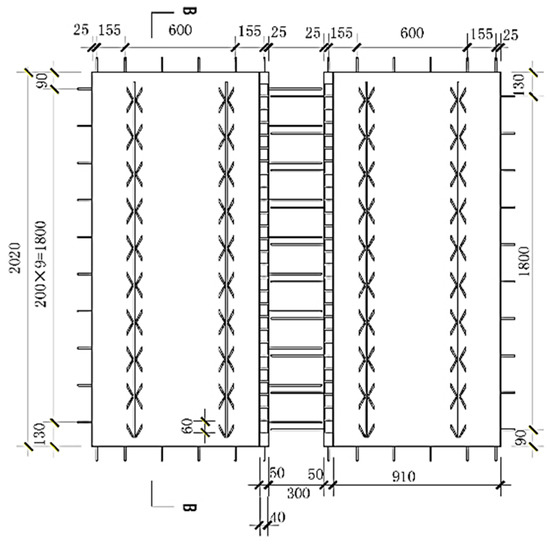
Figure 1.
CAD model dimension of CLHCPCS 1.
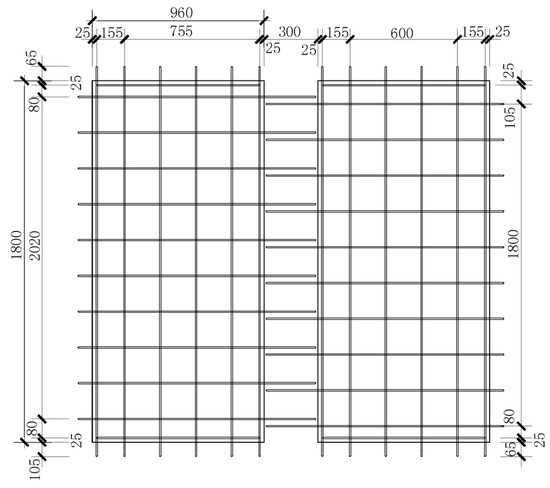
Figure 2.
The reinforcement diagram of the precast layer of the specimen.
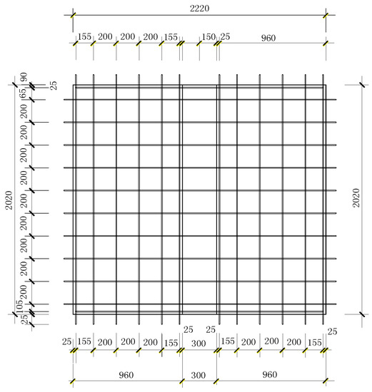
Figure 3.
The reinforcement diagram of the cast-in-place layer of the specimen.
3.2.2. Production of Composite Slab Specimen
The steel molds used in the test were prepared according to the requirements of assembled components. The reinforcement affixed with a strain gauge in advance was put into the mold, poured with concrete and cured for 28 days so that the precast part of the composite slab was basically prepared. The cast-in-place layer of the composite slab was prepared on top of it, poured with concrete and cured for 28 days, followed by a bending test of the CLHCPCS. The reinforcement of the CLHCPCS specimens, the preparation process and the final composite slab specimens are shown in Figure 4, Figure 5 and Figure 6.
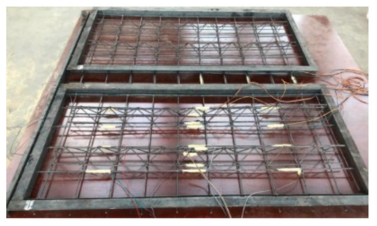
Figure 4.
The reinforcement of laminate bottom plate test specimens.
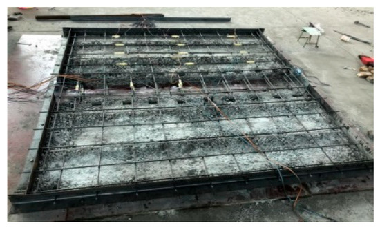
Figure 5.
The reinforcement of post−cast layer of composite slab.
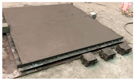
Figure 6.
The final composite slab specimens.
3.3. Optimal Design of CLHCPCS Splice Joint
In the joint form of a composite slab, a keyway−shaped joint [42], as shown in Figure 7, can only transmit shear force through the shear between keyways and cannot transmit the bending moment of the composite slab. A traditional form of composite slab joint [43], as shown in Figure 8, mainly bends the transverse reinforcement by 45°, anchors parts of the upper protruding part into the post−cast layer concrete, and transfers internal force through reinforcement. However, the disadvantage is that the overall performance is poor; composite slab barely bears great bending moments after splicing, quickly creating many cracks in the joint. The integrated joint form of a composite slab [44], as shown in Figure 9, improves the traditional joint form of a composite slab which can more reliably transmit bending moment, mainly through the following three ways: (1) Increasing the joint width to achieve stress transfer between reinforcements. Usually, when the joint distance exceeds 300 mm, some reinforcement can be extended from the precast part of the adjacent slab to achieve lap joint; (2) Reducing the reinforcement bending degree to steadily transfer the reinforcement stress in the adjacent slab, which is easier to achieve when the bending degree is less than 30°, and the anchorage length is increased. (3) Increasing the thickness of the post-cast concrete layer. When the thickness of the post-cast layer is ≥70 mm, by adding a distribution bar or a constructional steel bar in the longitudinal direction of the tensile bar, the integrity of the joint can be guaranteed. The joint of a composite slab with additional reinforcement [45], as shown in Figure 10, is to place additional reinforcement between the composite surfaces of the composite slab. Compared with other joint forms, the construction is more convenient and simpler with smoother force transfer, but only passable crack resistance is exhibited.
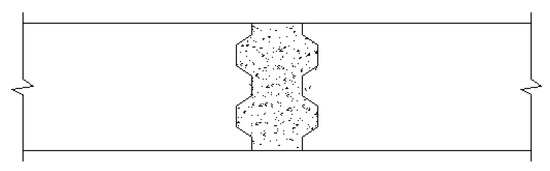
Figure 7.
The keyway of the composite slab.
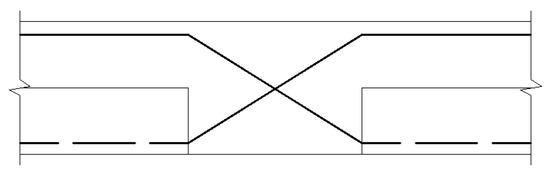
Figure 8.
45−degree bending angle seam of traditional composite slab.
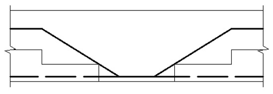
Figure 9.
Overall seam form of the composite slab composite slab.
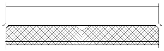
Figure 10.
The splicing structure in the form of the additional steel bars.
To sum up, each joint form has respective advantages and disadvantages. Therefore, it is still necessary to build a new joint to improve the performance of force transmission between composite slabs, reduce secondary construction at the joint, limit the joint cracking and control the joint development, and increase the crack resistance at the joint, thereby improving the bearing capacity of the composite slab. Based on the CLHCPCS, this study designed a new joint, studied the crack resistance and joint development of CLHCPCS under the new joint, calculated the theoretical cracking load and compared it with the test value. The specific form of the new joint is as follows: The splice joint is a downward groove arranged in a parallel direction. The groove has a dimension of 40 mm × 60 mm, which sinks downward by 20 mm and is linearly arranged with a spacing 50 mm. The detailed dimensions of the joint are shown in Figure 11, Figure 12 and Figure 13.
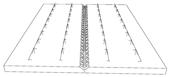
Figure 11.
Top view of seam position of CLHCPCS.

Figure 12.
Side op view of seam position of CLHCPCS.
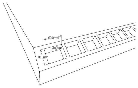
Figure 13.
Schematic diagram of the seam of CLHCPCS size.
3.4. Test Data Collection
The strain gauges and displacement gauges are arranged as shown in Figure 14, Figure 15 and Figure 16. During the test, the cracks at each stage, their development and width were carefully observed. After the test, the results were analyzed and sorted out to plot the deflection−load curves of composite slab cracks.
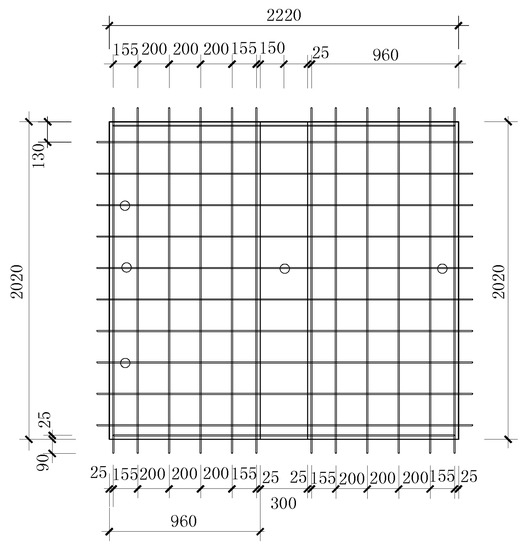
Figure 14.
The lay−out diagram of concrete strain gauge lay−out on the lower surface.
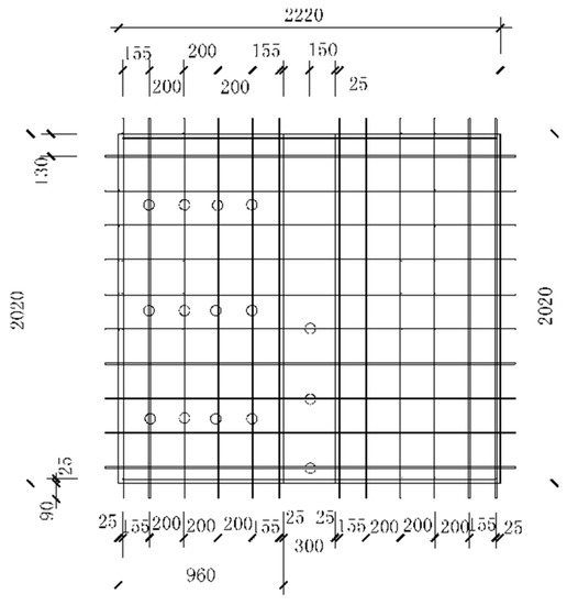
Figure 15.
The lay−out diagram of stacked floor tensioned steel strain gauge.
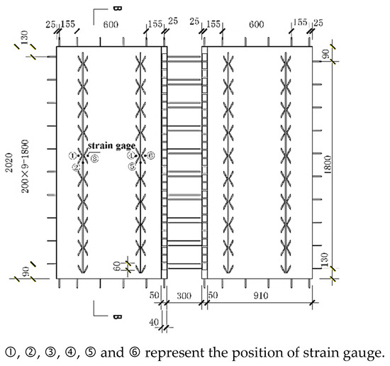
Figure 16.
Lay−out of truss reinforcement strain gauges.
3.5. Test Loading
During the test, the 50 t pressure sensor was used to control and measure the force, and the distribution beam−hydraulic jack system achieved the sustained load. The loading device is shown in Figure 17. A layer of latex paint was brushed on the surface of the composite slab. After the latex paint was formed, a pencil was used to divide the composite slab into 50 mm × 50 mm meshes.
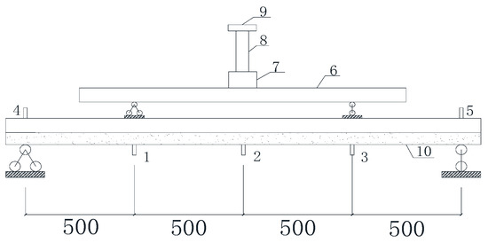
Figure 17.
The lay−out diagram of the test loading device. 1–5—displacement meter; 6—distribution beam; 7—sensor; 8—jack; 9—reaction frame; 10—composite slab.
3.6. Flexural Test Data Analysis of CLHCPCS
The lateral crack distribution of CLHCPCS and ordinary concrete composite slab during a failure is compared as shown in Figure 18a–c.
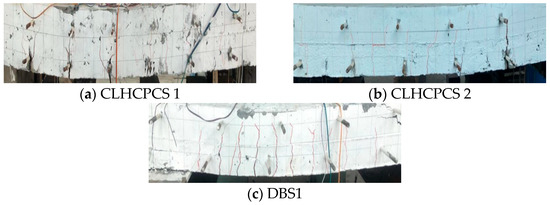
Figure 18.
Comparison of crack distribution when CLHCPCS and ordinary concrete composite slab fail.
The bottom penetrating crack patterns of the three composite slabs are shown in Figure 19a–c.
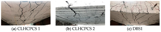
Figure 19.
The Crack pattern at the bottom of the three composite slabs.
3.6.1. Analysis of Load−Strain Curve Results of CLHCPCS Reinforcement
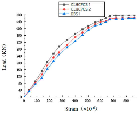
Figure 20.
Load−strain curve of CLHCPCS reinforcement.
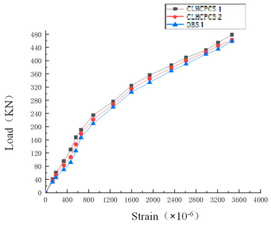
Figure 21.
Load−strain curve diagram of longitudinal reinforcement bar of the composite slab.
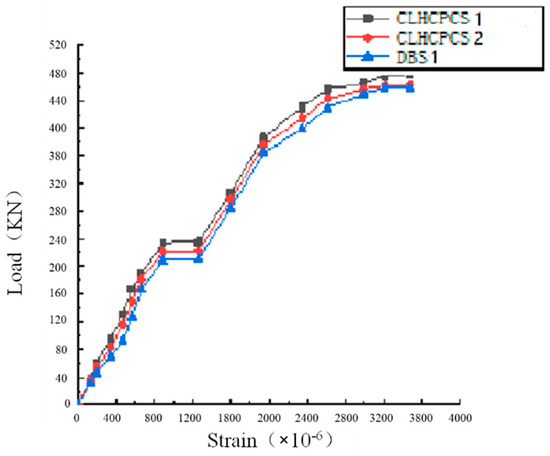
Figure 22.
Load−strain curve diagram of rebar joints of the composite slab.
Figure 20 shows that at the beginning of the load increase, the strain of the three kinds of composite slab truss bars increases linearly. Under applied uniformly distributed load 8.90 kN/m2, the concrete cracks appear. Along with the crack development, concrete begins to deactivate. The load is gradually borne by the longitudinal tensile bar and lower chord of the truss bar until the composite slab damage occurs. The strain value grows slowly and gradually stabilizes in the later stage. The longitudinal tensile bar and the lower chord of the truss bar form an excellent primary and secondary beam structure, with the lower chord bearing part of the force transmitted by the reinforcement. The composite slab has good mechanical performance during the whole load−holding process.
As can be seen from Figure 21, when a load of CLHCPCS 1 is less than 125 kN, the strain of the longitudinal tensile bar exhibits linear growth. When a load of CLHCPCS 2 is less than 70 kN, the strain of the tensile bar displays linear growth; when the load of DBS1 is about 65 kN, the strain growth shows a linear state. Subsequently, the strain growth rate is accelerated, mainly because the central axis of the composite slab precast layer rises, and the load borne by the concrete begins to be shared by the reinforcement in the tensile zone and a part of the truss bar. The tensile bar in the middle of the span has the largest strain, gradually decreasing from the middle to both sides. When the load increases, the crack enlarges, with the crack development rate increasing and the stress−strain of the reinforcement in the tensile zone increasing. The reinforcement gradually reaches the yield limit when the load approaches the ultimate bearing capacity. After failure, the composite slab is slowly unloaded, with the composite slab tending to stabilize and the stress and strain values of the reinforcement reaching a fixed value.
As can be seen from Figure 22, CLHCPCS1 exhibits a higher curve than CLHCPCS 2 and DBS1, which proves that the joint form of CLHCPCS 1 improves the crack resistance of the composite slab. An inflection point occurs in strain after the cracking load is achieved, and then the strain value of the splice bar increases more rapidly.
3.6.2. Load−Strain Curve Diagram and Result Analysis of CLHCPCS Concrete
The load−strain of CLHCPCS concrete is shown in Figure 23.
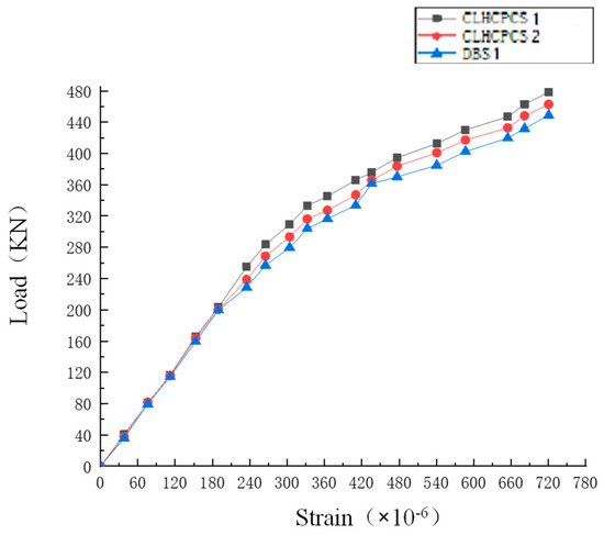
Figure 23.
CLHCPCS concrete load−strain curve diagram.
As seen in Figure 23, the three composite slabs exhibit the same concrete changes in the early stage. The concrete strain initially increases linearly. With the continuous increase of load, the concrete strain increases significantly. For this reason, the composite slab is initially in the elastic stage, and then the concrete begins to appear cracks. With the crack penetration, the concrete gradually deactivates. When a load of CLHCPCS 2 reaches about 450 kN, the concrete in the tensile zone reaches the maximum crack width of 1.5 mm, and then CLHCPCS 2 suffers bending failure rather than the failure of the composite surface.
3.6.3. Bearing Capacity Analysis of CLHCPCS
(1) Calculation of the service load value
According to the “Concrete Structure Design Code” [46], the additional constant load value is taken as 2.34 kN/m2, the live load value is taken as 2.0 kN/m2, and the floor concrete bulk weight is taken as 21.1 kN/m3.
(2) Calculation of the design load value
Permanent load control combination:
Variable load control combination:
where is the dead weight of the floor, is the additional constant load value, is the live load value of the floor.
(3) Cracking load calculation of CLHCPCS
The cracking load is calculated according to the “Concrete Structure Design Code” [46,47], and the calculation formula is as follows:
In the above equation is the coefficient of prestressed reinforcement. If there is no prestressed reinforcement in CLHCPCS, ; is the influence coefficient regarding the resistance moment plasticity of the concrete member section, and the composite slab is rectangular, so it is 1.55; is the axial tensile strength of concrete, 2.01 ; W0 is the cross−section resistance moment, which is calculated according to Equation (2):
For CLHCPCS, when the uniformly distributed load is considered, the edge−bearing coefficient analysis method can be used for calculation. For a four−sided, simply supported slab, the calculation can be made in two ways:
The cracking load is taken as the minimum of the two loads, namely:
where, , are the directional bending moment coefficients. For full−size model CLHCPCS 1, l01/l02 = 0.9, is 0.045, is 0.029.
Then, ,
Then, the theoretically uniformly distributed cracking load of CLHCPCS 1 is , and the cracking load is = 129.1 kN.
Similarly, the theoretically uniformly distributed cracking load of CLHCPCS 2 and DBS1 can be calculated, as shown in Table 10.
Table 10.
Cracking load statistics of the superimposed surface of the specimen.
(4) Calculation of the ultimate bearing capacity of CLHCPCS
CLHCPCS is double reinforced with a precast layer, and cast-in-place layer, the specifications of the upper and lower reinforcement are consistent in practical engineering. The precast and cast-in-place layers adopt a truss bar to strengthen the connection between the upper and lower layers. As a result, the flexural typical section formula of rectangular section is no longer applicable. The ultimate bearing capacity of CLHCPCS was calculated by the plastic line method. The plastic line method estimates the ultimate bearing capacity by assuming boundary conditions, which was first proposed by Ingerslev [47] and improved and extended by Johansen [48,49]. In the plastic line method, it is hypothesized that when the CLHCPCS reaches the ultimate load, the tensile bar reaches the yield, and its ultimate bending moment can be calculated through Equation (5) [50]:
In the above equation, and respectively represent the cross−sectional area of the longitudinal tensile bar inside the composite slab in the direction and ; , respectively represent the internal lever arm of the longitudinal tensile bar inside the composite slab in the direction and ; , respectively represent the design values of tensile reinforcement strength in the inner cross−section of the composite slab in the direction and ; , respectively represent the design values of tensile reinforcement strength in the bearing section of the composite slab in the direction and ; , , , are the internal lever arm coefficients, which take the values 0.95.
According to the setting of boundary conditions and the location of the plastic line, the formula of the ultimate bearing capacity of CLHCPCS is as follows:
In the above equation, the position of the plastic line is determined by the parameters , and . Where , , ,, .
According to the above conditions, the theoretical limit uniformly−distributed load of CLHCPCS 1 was calculated by substituting relevant data, and the ultimate bearing capacity is F = 350.3 kN.
In the same way, the theoretical ultimate bearing capacity of CLHCPCS 2 and DBS1 can be calculated, as shown in Table 11.
Table 11.
Cracking load statistics of the superimposed surface of the specimen.
Comparing the theoretical and experimental values of CLHCPCS1, CLHCPCS2, and DBS1 ordinary composite slab, the cracking load of CLHCPCS1 is higher than that of CLHCPCS2. Both are higher than that of DBS1 ordinary composite slab. The ultimate bearing capacity of CLHCPCS2 is higher than that of CLHCPCS1. Both are higher than that of DBS1 ordinary composite slab, indicating that the various CLHCPCS performance indexes are higher than the ordinary concrete composite slab and meet the specification requirements. There is little difference between the calculated and experimental results, so the plastic line method can be used to calculate the flexural capacity of CLHCPCS.
4. Finite Element Analysis of CLHCPCS
4.1. Selection of Finite Element Software
The finite element method [51] is widely used in structural analysis. In this study, the finite element analysis software ANSYS was used for the finite element modelling of CLHCPCS. The simulation results were used to evaluate the ultimate bearing capacity of the structure and facilitate the optimal design of the structure.
4.2. Finite Element Model Establishment and Material Attribute Definition
The geometric model has mainly divided into the following parts: a precast layer model of a composite slab, a cast-in-place layer model of a composite slab, and a steel grid model (including longitudinal tensile bar, distribution bar and truss bar). After modelling separately, it is then assembled as a whole component. The model is shown in Figure 24, Figure 25 and Figure 26.
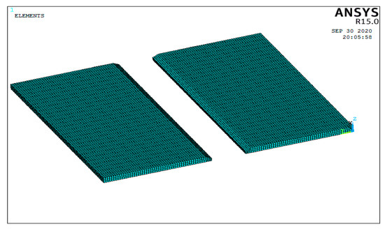
Figure 24.
The precast layer model of a composite slab.
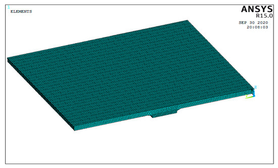
Figure 25.
The cast-in-place layer model of a composite slab.
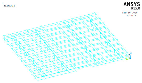
Figure 26.
The steel grid model of a composite slab.
Concrete cracking and crushing can be well achieved in solid 65. After all geometric models are established, the corresponding material properties are added to each part. In this simulation, the reinforcement unit model selects link8 unit in the link unit, and the concrete unit is the solid 65 unit.
4.3. Finite Element Model Establishment of CLHCPCS
(1) Basic assumptions of the model [52]:
Considering that the composite slab is divided into a precast layer and a cast-in-place layer in the actual engineering practice, the concrete has differences due to the curing cycle. In this model, it is hypothesized that the precast layer and cast-in-place layer are in close contact with each other, and the reinforcement unit and concrete unit are bonded well and deformed consistently.
(2) Unit selection and grid division
The reinforcement unit shares a joint with the concrete unit. The mesh division determines the speed and accuracy of ANSYS finite element software processing [52,53]. The unit grid should be manageable in the division to prevent stress concentration. 50 mm was taken as the size for the grid division of solid65 and link8 units.
(3) Load definition and boundary condition constraint definition
Considering the actual project status, the constraint definition of CLHCPCS adopts consolidation constraints at both ends and simple support constraints at the other end. That is, consolidation end constraint is displacement in three directions, simple support end constraint is displacement in two directions, and the other direction supports the free movement. Considering the Saint-Venant principle and to comply with the actual test conditions, an I-beam support (width 200 mm, height 200 mm) is added under the CLHCPCS. The constraint mode between the tensile bar and the truss bar, concrete elements is all embedded constraint mode. Considering the relative slip between the I-beam support and the CLHCPCS, the constraint mode between the support and CLHCPCS is determined as TIE constraint mode. The loading mode is to apply surface load on the top surface of the cast-in-place layer of CLHCPCS.
4.4. Simulated Bending Test of CLHCPCS and Analysis of Simulation Results
The bending test of CLHCPCS was carried out by applying surface load on the top surface of the cast-in-place layer of the composite slab. The load curves were plotted based on the stress and strain values of cast-in-place layer measurement points of the composite slab. The test model and related elastic-plastic parameters were referenced in the literature [53]. The resulting simulation results were analyzed with the test process results. The specific deformation cloud diagrams include the total displacement stress cloud diagram of CLHCPCS, the equivalent stress cloud diagram of CLHCPCS, and the failure pattern of CLHCPCS, as shown in Figure 27 and Figure 28.
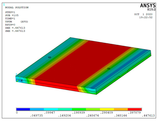
Figure 27.
The total displacement stress cloud diagram of CLHCPCS under the ultimate load.
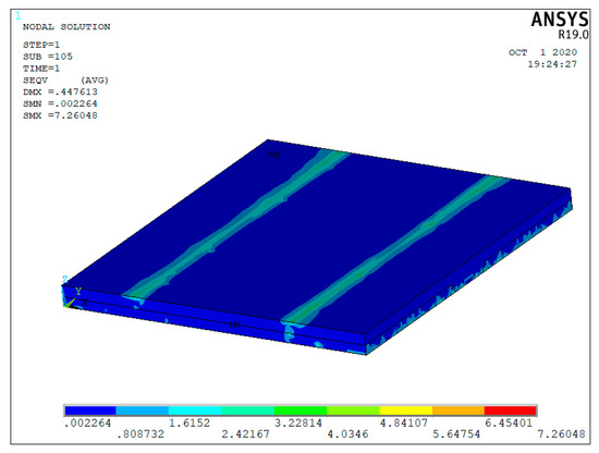
Figure 28.
Equivalent stress cloud diagram of the CLHCPCS under ultimate load.
Figure 27, Figure 28 and Figure 29 show that the maximum stress and maximum deflection of CLHCPCS in midspan are 18.87 mm, gradually decreasing from midspan to both sides. When the load increases from 0 to 100 kN, the CLHCPCS is in the elastic stage, with the deflection value increased linearly and the reinforcement controlled within the elastic range. The load is further increased. When the load approaches 120 kN, the inflection point begins to appear. At this time, the partial bottom surface of the precast layer begins to crack, the overall stiffness of the composite slab decreases, and the slope of its deflection also begins to increase.
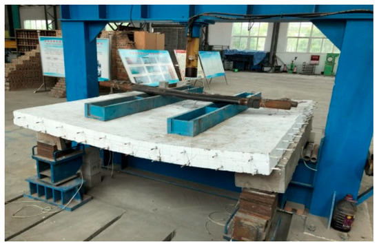
Figure 29.
Failure mode of CLHCPCS under ultimate load.
The stress and deformation cloud diagrams of CLHCPCS steel grid are shown in Figure 30, Figure 31, Figure 32, Figure 33 and Figure 34.
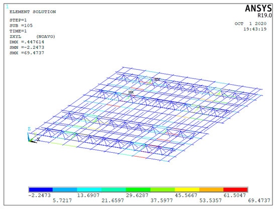
Figure 30.
Stress cloud diagram of steel bar grid under ultimate load.
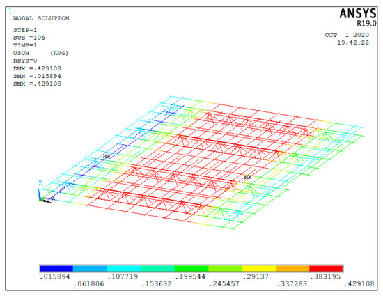
Figure 31.
Deformation cloud map of reinforced grid under ultimate load.
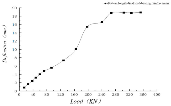
Figure 32.
Load−deflection curve of cross−middle tension steel.
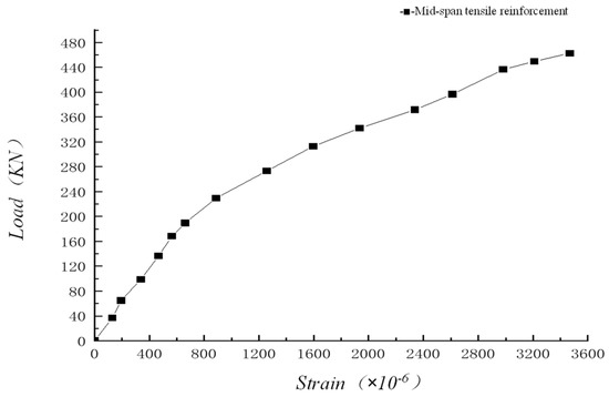
Figure 33.
Stretch−load curve of mid−span tensile steel.
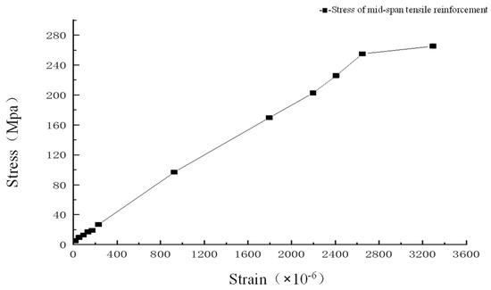
Figure 34.
Stress−strain relationship curve of span−stayed steel bars.
According to the figure above, when the load is not increased to 125 kN, the CLHCPCS does not crack. The longitudinal tensile bar is not affected much at this time, with the strain value exhibiting a linear trend with the increase of the load. As the loading increases gradually, cracks occur in the composite slab, the loading borne by the concrete in the tensile zone is gradually borne by the tensile bar, and the strain value increase rate gets faster and faster. When the CLHCPCS is about to rupture, an obvious inflection point appears on the curve graph as the strain increases. After the failure of the composite slab, the load is slowly reduced to zero, and the stress−strain value tends to stabilize.
Figure 35, Figure 36 and Figure 37 show the stress and deformation cloud diagrams of CLHCPCS truss bars (in the screenshot).
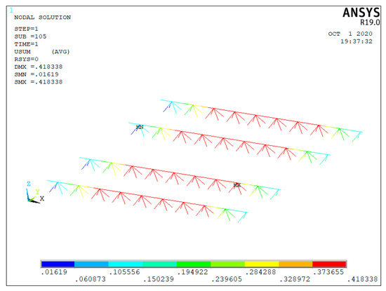
Figure 35.
Deformation cloud diagram of truss rib under ultimate load.
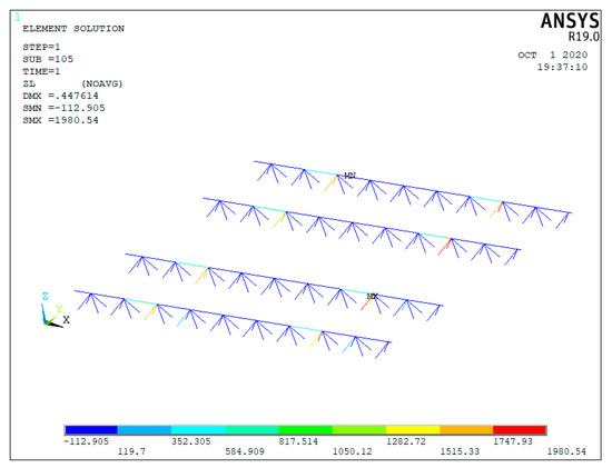
Figure 36.
Stress cloud diagram of truss rib under ultimate load.
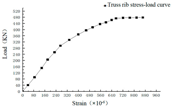
Figure 37.
Truss rib stress−load curve.
According to the figure above, the strain value of the truss bar increases linearly with the loading increase, and the increase is slight. When the concrete cracks, the loading is jointly borne by the precast tensile bar and the lower chord of the truss bar. With the increase of load, the failure occurs at 350 kN. As shown in Figure 32, Figure 33 and Figure 34, the strain value, stress value and deflection value of the truss bar reach the maximum at this time, and the analysis results are consistent with the test results.
To sum up, when the load increases slightly, the various indexes of CLHCPCS are still in linear change. After the cracking load is reached, the deflection point begins to appear, with the increase rate gradually accelerated. The overall stress of the composite slab is gradually borne by the tensile bar and truss bar instead of the compressive concrete. Finally, the ultimate bearing capacity is reached, followed by composite slab reinforcement and structure damage yielding.
Comparative analysis of ultimate bearing capacity between CLHCPCS and ordinary concrete composite slab.
Based on the existing research [54], the test data and finite element analysis results of CLHCPCS are comparatively analyzed with those of ordinary concrete composite slab, with the analysis results shown in Figure 38.
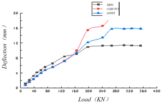
Figure 38.
CLHCPCS and ordinary composite slab load−deflection curve.
According to Figure 38, CLHCPCS has a lower deflection growth rate than ordinary concrete composite slab in the early stage. CLHCPCS has a higher ultimate bearing capacity than the ordinary concrete composite slab. There is little difference in the deflection growth rate between the CLHCPCS test value and the finite element model in the early stage. With the increase in load, the experimental model exceeds the mathematical simulation, but the ultimate bearing capacity is similar.
5. Results
In this study, ceramsite light high titanium heavy slag prefabricated concrete composite slabs were prepared by adding ceramsite to high titanium heavy slag, and the CLHCPCS composite slabs 1, CLHCPCS composite slabs 2 and DBS1 composite slabs prepared using this kind of ceramsite concrete, subject to the bending test and seam line improvement test research. The formula for calculating the ultimate bearing capacity of CLHCPCS laminated slab was derived theoretically. The finite element analysis software ANSYS was used to simulate the bending process of CLHCPCS composite plate, and the simulation results were compared with the experimental results. Through the above research, the main results are as follows:
(1) The weight of CLHCPCS composite slab was reduced by adding shale ceramsite or fly ash ceramsite and other admixtures. The results showed that when shale ceramsite was added, the density of CLHCPCS composite slab concrete decreased by 12.0%, and the mass decreased by 171.40 kg under the full−scale model. When fly ash ceramsite is added, the apparent density of CLHCPCS composite slab concrete is reduced by 10.6%, and the mass is reduced by 151.39 kg under the full−scale model.
(2) Through the mechanical properties test of the concrete, the test results are analyzed by range variance analysis. It was obtained that when the shale ceramsite is added, the mechanical properties are the largest when the dosage is 20%, and it decreases with the increase of shale ceramsite dosage. When the content of fly ash ceramsite is 30%, the mechanical properties are the largest, and increase first and then decrease with the increase of fly ash ceramsite content.
(3) By comparing the weight loss ratio and strength index of shale ceramsite concrete and fly ash ceramsite concrete, it was found that the mechanical strength of fly ash ceramsite is higher than that of shale ceramsite, while the weight loss of fly ash ceramsite is similar to that of shale ceramsite.
(4) Through the improved test of CLHCPCS laminated slab seam line, compared with CLHCPCS laminated slab 1 and CLHCPCS laminated slab 2, it was found that the test cracking load of CLHCPCS laminated slab 1 is higher than that of CLHCPCS laminated slab 2, which indicates that the improved seam line form can effectively reduce cracks. The results may provide useful insights to practitioners.
(5) By comparing CLHCPCS2 laminated slab with ordinary concrete laminated slab DBS1, it was found that the ultimate bearing capacity of CLHCPCS2 laminated slab is greater than that of ordinary concrete laminated slab DBS1, which indicates that the new ceramsite high titanium slag concrete can effectively improve the bearing capacity of the laminated slab.
(6) The splicing model of CLHCPCS composite slab is established by ANSYS and the bending test simulation is carried out. The failure mode, the distribution of stress and strain and the ultimate bearing capacity of the model under the plastic strand method were obtained. The results are consistent with the theoretical and experimental analysis results, and the simulation analysis results are not much different from the experimental results, indicating that the finite element model created according to the steel element model and the concrete element model is correct. According to the overall trend of the load curve of CLHCPCS composite slab simulation and test, it is similar.
6. Conclusions
In this study, high titanium heavy slag was used as coarse and fine aggregate to prepare high titanium heavy slag concrete, forming high titanium heavy slag concrete composite slab. Its bearing capacity is greater than that of an ordinary concrete composite slab, which proves the feasibility and superiority of using this industrial slag.
Through this research, it was found that the use of fly ash ceramsite as part of the coarse aggregate of concrete reduces the apparent density of CLHCPCS composite slab concrete, thereby achieving the purpose of reducing the weight of CLHCPCS composite slab. It was proven that the use of ceramsite as concrete can improve the strength of concrete and reduce early cracking. For prefabricated composite plate components, reducing weight is convenient for construction, reducing load effect and reducing costs.
For precast composite slab components, the optimized joint form can further facilitate the construction and improve the slab stress conditions.
This study fully proves the reliability of the physical and mechanical properties of CLHCPCS, which meets or even exceeds the relevant standard requirements of laminated plate components.
The prefabricated composite slab is an important PC component of prefabricated building structures. The research results have strong theoretical and practical engineering reference value for promoting the use of high titanium slag concrete prefabricated composite slab, promoting the utilization of high titanium heavy slag industrial solid waste resources, realizing green, low carbon environmental protection, optimizing the overall stability of composite slab components and construction hoisting efficiency, and improving economic efficiency.
Limitations and future research directions: (1) Limited by the time and cost of the project, this study only tests three plates. Considering the randomness of the test process and the deviation of the midway of the test, more groups of test analysis can be carried out in the future to make the research data of this new composite plate more reliable. (2) The composite slab is divided into a precast layer and a cast-in-place layer. In this study, both the precast layer and the cast-in-place layer are ceramsite light high titanium heavy slag concrete. It can also be considered that when the precast layer is CLHCPCS composite slab, the cast-in-place layer is the influence of the superposition of ordinary concrete, which makes it more suitable for factory production and on−site construction of prefabricated structures.
Author Contributions
Conceptualization, S.W. and J.S.; methodology, J.S. and T.J.; software, S.W. and C.D.; validation, J.S., R.Y.M.L. and L.Z.; formal analysis, J.S.; investigation, J.S., S.W. and T.J.; resources, J.S. and R.Y.M.L.; data curation, C.D.; writing—original draft preparation, S.W. and J.S.; writing—review and editing, J.S., R.Y.M.L., C.D., T.J. and L.Z.; visualization, J.S. and C.D. supervision, J.S.; project administration, J.S.; funding acquisition, J.S. All authors have read and agreed to the published version of the manuscript.
Funding
This research was funded by [Pangang Group Co., Ltd. & Panzhihua University’s Scientific Research Collaborative Innovation Platform Technology Research and Development Project (the 1st batch)—Sub−project of Pangang Group Co., Ltd. about “High Titanium Blast Slag Preparation Prefabricated Concrete PC Components Research”] grant number [HX2022096] and [Starting Research Fund: Research on the Technology and Industry of a New Type of Prefabricated High−Titanium Heavy Slag Concrete Composite Board] grant number [035200192]. And The APC was funded by [035200192].
Acknowledgments
This study was financially supported by Starting Research Fund: Research on the Technology and Industry of a New Type of Prefabricated High−Titanium Heavy Slag Concrete Composite Board (no. 035200192).
Conflicts of Interest
The authors declare no conflict of interest.
References
- Zhao, Y.H. Features and construction of prefabricated buildings. In Applied Mechanics and Materials; Trans Tech Publications Ltd.: Wollerau, Switzerland, 2014; Volume 580. [Google Scholar]
- Andersen, E.S.; Jessen, S.A. Project Maturity in Organisations. Int. J. Proj. Manag. 2003, 21, 457–461. [Google Scholar] [CrossRef]
- Li, X.; Wang, C.; Alashwal, A.; Bora, S. Game analysis on prefabricated building evolution based on dynamic revenue risks in China. J. Clean. Prod. 2020, 267, 121730. [Google Scholar] [CrossRef]
- Jia, G.; Chen, Y.; Xue, X.; Chen, J.; Cao, J.; Tang, K. Program management organization maturity integrated model for mega construction programs in China. Int. J. Proj. Manag. 2011, 29, 834–845. [Google Scholar] [CrossRef]
- Yee, A.A. Social and Environmental Benefits of Precast Concrete Technology. PCI J. 2001, 46, 14–19. [Google Scholar] [CrossRef]
- Yee, A.A.; Eng, P.H.D. Structural and Economic Benefits of Precast/Prestressed Concrete Construction. PCI J. 2001, 46, 34–42. [Google Scholar] [CrossRef]
- Veljković, M. Influence of load arrangement on composite slab behaviour and recommendations for design. J. Constr. Steel Res. 1998, 45, 149–178. [Google Scholar] [CrossRef]
- Fard, M.M.; Terouhid, S.A.; Kibert, C.; Hakim, H. Safety concerns related to modular/prefabricated building construction. Int. J. Inj. Control. Saf. Promot. 2015, 24, 10–23. [Google Scholar] [CrossRef]
- Ning, H.; Song, Y.; Wang, Z.; He, C.; Ruan, S. Utilization of Silt, Sludge, and Industrial Waste Residues in Building Materials: A Review. J. Appl. Biomater. Funct. Mater. 2022, 20, 228080002211147. [Google Scholar]
- Akinmusuru, J.O. Potential beneficial uses of steel slag wastes for civil engineering purposes. Resour. Conserv. Recycl. 1991, 5, 73–80. [Google Scholar] [CrossRef]
- Brand, A.S.; Roesler, J.R. Steel furnace slag aggregate expansion and hardened concrete properties. Cem. Concr. Compos. 2015, 60, 1–9. [Google Scholar] [CrossRef]
- Besma, M.; Ali, N. Replacement of Natural Gravel with Waste Glass in Concrete. IOP Conf. Ser. Mater. Sci. Eng. 2020, 870, 012147. [Google Scholar]
- Jiang, X.; Xiao, R.; Bai, Y.; Huang, B.; Ma, Y. Influence of waste glass powder as a supplementary cementitious material (SCM) on physical and mechanical properties of cement paste under high temperatures. J. Clean. Prod. 2022, 340, 130778. [Google Scholar] [CrossRef]
- Xiao, F. Performance Research of Titanium Slag Concrete. Master’s Thesis, Chongqing University, Chongqing, China, 2004. [Google Scholar]
- Jiang, H. Research and Application of High Titanium Heavy Slag Aggregate of High Performance Concrete. Master’s Thesis, Wuhan University of Technology, Wuhan, China, 2011. [Google Scholar]
- Sun, J. Fundamental Research on Application of Complex High Titanium Heavy Slag Concrete. Master’s Thesis, Chongqing University, Chongqing, China, 2006. [Google Scholar]
- Sun, J.; Chen, W.; Li, B. Influence of Filling Micro Mist to the High Titanium and Dry Slag Mortar Performance. Shanxi Archit. 2006, 20, 157–158. [Google Scholar]
- Zhou, X.; Li, J.; Luo, C. A Research on High—Ti Blast Furnace Slag Crushed Stone Applied for Concrete Aggregate. Iron Steel Vanadium Titan. 2001, 4, 43–46+68. [Google Scholar]
- Li, X.; Chen, W.; Li, X. Experimental Study on Seismic Performance of High Strength Concrete Columns with High Titanium Heavy Slag as Coarse and Fine Aggregates. Build. Struct. 2013, 9, 96–100. [Google Scholar]
- Chen, W.; Jiao, T.; Zhang, Q.; Sun, J.-K. Study on Mix Design of High-Titanium Slag Aggregate Concrete Mixed Fine Coal Ash. Archit. Technol. 2010, 8, 758–759. [Google Scholar]
- Chen, T.; Huang, W.; Sun, S.; Jiao, J.-K. Experimental Study on Normal Section Strength of High Titanium Heavy Slag Reinforced Concrete Beams. Sichuan Build. Sci. 2009, 4, 51–53. [Google Scholar]
- Chu, J.; Lei, Y. Mechanical Property Analysis on Steel Plate Joint of Concrete-Filled Square Steel Tubular Column with Rc Beam. Sichuan Build. Sci. 2009, 35, 36–39, 53. [Google Scholar]
- Yousuf, L.S. Nonlinear dynamics investigation of flexural stiffness of composite laminated plate under the effect of temperature and combined loading using Lyapunov exponent parameter. Compos. Part B Eng. 2021, 219, 108926. [Google Scholar] [CrossRef]
- Belardi, V.G.; Fanelli, P.; Vivio, F. Ritz method analysis of rectilinear orthotropic composite circular plates undergoing in-plane bending and torsional moments. Mech. Adv. Mater. Struct. 2019, 28, 963–979. [Google Scholar] [CrossRef]
- Arasan, U.; Marchetti, F.; Chevillotte, F.; Jaouen, L.; Chronopoulos, D.; Gourdon, E. A simple equivalent plate model for dynamic bending stiffness of three-layer sandwich panels with shearing core. J. Sound Vib. 2021, 500, 116025. [Google Scholar] [CrossRef]
- Gerritse, A. Design Considerations for Reinforced Lightweight Concrete. Int. J. Cem. Compos. Lightweight Concr. 1981, 3, 57–69. [Google Scholar] [CrossRef]
- Agrawal, Y.; Gupta, T.; Sharma, R.; Panwar, N.; Siddique, S. A Comprehensive Review on the Performance of Structural Lightweight Aggregate Concrete for Sustainable Construction. Constr. Mater. 2021, 1, 39–62. [Google Scholar] [CrossRef]
- Wang, X.; Huang, Y.; Wu, G.; Fang, C.; Li, D.; Han, N.; Xing, F. Effect of nano-SiO2 on strength, shrinkage and cracking sensitivity of lightweight aggregate concrete. Constr. Build. Mater. 2018, 175, 115–125. [Google Scholar] [CrossRef]
- Qiu, J.; Wang, B.; Xiao, G. Degradation Law of Mechanical Properties of Coal Gangue Ceramsite Concrete under Freeze-Thaw Cycles. New Build. Mater. 2020, 47, 159–162, 172. [Google Scholar]
- Sun, X.; Liu, J. Study on Failure Properties of Shale Ceramsite Concrete. Build. Constr. 2019, 41, 327–328, 331. [Google Scholar]
- Yang, X. Study on the Performance of Inorganic Thermal Insulation Material Used for Wall Panel of Assembly Building Structures. Master’s Thesis, Qinghai University, Qinghai, China, 2019. [Google Scholar]
- Huang, P.; Liu, F. Study on Preparation and Mechanical Properties of Gravel Shale Ceramsite Lightweight Aggregate Concrete. Anhui Archit. 2020, 27, 179–180. [Google Scholar]
- Yu, M. Study on Physical and Mechanical Properties of Wheat Straw Fiber Porous Ceramsite Concrete. Master’s Thesis, Henan University, Henan, China, 2019. [Google Scholar]
- Tian, R. Research on Mechanical Properties of Ceramsite Concrete Ultra-Long Partition Walls. Master’s Thesis, Yangzhou University, Yangzhou, China, 2019. [Google Scholar]
- Yang, B. Study on Durability Optimization of Lightweight Concrete. Master’s Thesis, Tianjing University, Tianjing, China, 2018. [Google Scholar]
- Li, K. Study on Lightweight and Mechanical Properties of Prefabricated Composite Board of High Titanium Heavy Slag Concrete. Master’s Thesis, Xihua University, Xihua, China, 2019. [Google Scholar]
- Domagała, L. Size Effect in Compressive Strength Tests of Cored Specimens of Lightweight Aggregate Concrete. Materials 2020, 13, 1187. [Google Scholar] [CrossRef]
- Yardim, Y.; Waleed, A.; Jaafar, M.S.; Laseima, S. AAC-concrete light weight precast composite floor slab. Constr. Build. Mater. 2013, 40, 405–410. [Google Scholar] [CrossRef]
- Afefy, H.M.; Sennah, K.; Tu, S.; Ismail, M.; Kianoush, R. Development and study of deck joints in prefabricated concrete bulb-tee bridge girders: Experimental evaluation. Bridg. Struct. 2015, 11, 55–71. [Google Scholar] [CrossRef]
- He, L.; Zhang, X.; Liu, L. The Use of Orthogonal Test Results Analysis Method in Scientific and Technical Papers. Acta Radiol. 2007, 19, 340–341. [Google Scholar]
- Leik, R. Experimental Design and the Analysis of Variance; Sage Publications: Thousand Oaks, CA, USA, 1997. [Google Scholar]
- Anhui Provincial Department of Construction. Technical Code for Composite Slab Concrete Shear Wall Structures; Anhui Provincial Department of Construction: Hefei, China, 2008. [Google Scholar]
- Housing and Construction Bureau of Shenzhen Municipality. Technical Specification for Precast Assembled Monolithic Reinforced Concrete Structures; Housing and Construction Bureau of Shenzhen Municipality: Shenzhen, China, 2009. [Google Scholar]
- Heilongjiang Provincial Department of Housing and Urban-Rural Development. Technical Specification for Precast Assembly Monolithic Concrete Shear Wall Structures; Heilongjiang Provincial Department of Housing and Urban-Rural Development: Harbin, China, 2010. [Google Scholar]
- Jiangsu Provincial Department of Housing and Urban-Rural Development. Technical Specification for Precast Assembly Monolithic Concrete Shear Wall Structures; Jiangsu Provincial Department of Housing and Urban-Rural Development: Nanjing, China, 2011. [Google Scholar]
- Zhao, J.; Xu, Y.; Huang, X. Code for Design of Concrete Structures(Gb 50010-2010). Constr. Sci. Technol. 2015, 10, 28–30. [Google Scholar]
- Chen, S. Experiment and Analysis of Pk Prestressed Concert Composite Slab on Simple Support. Master’s Thesis, Hu Nan University, Changsha, China, 2012. [Google Scholar]
- Johnson, K.W. Publisher’s Announcement Yield-Line Theory. Mag. Concr. Res. 1962, 14, 54. [Google Scholar] [CrossRef]
- Johansen, K.W. Yield-Line Formulae for Slabs. 1972. Available online: https://www.taylorfrancis.com/books/mono/10.1201/9781482272321/yield-line-formulae-slabs-johansen (accessed on 10 July 2022).
- Wu, F.-B.; Huang, H.-L.; Chen, W.; Zhou, X.-H. Ultimate bearing capacity of concrete two-Way composite slabs with precast concrete ribbed panel. J. Civ. Archit. Environ. Eng. 2011, 33, 34–40. [Google Scholar]
- The Finite Element Method: Its Basis and Fundamentals. In The Finite Element Method: Its Basis and Fundamentals, 7th ed.; Zienkiewicz, O.C., Taylor, R.L., Zhu, J.Z., Eds.; Butterworth-Heinemann: Oxford, UK, 2013. [Google Scholar]
- Ma, X. Study on Mechanical Behaviors of Reinforced Concrete Superimposed Slabs with Steel Bar Truss. Master’s Thesis, DongNan University, Jiangsu, China, 2017. [Google Scholar]
- Liu, B. Experimental and Numerical Study of Concrete Composite Hollow Core Slab with Precast Prestressed Concrete Ribbed Panel. Master’s Thesis, HuNan University, Hunan, China, 2016. [Google Scholar]
- Sun, B.; Ding, D.-X.; Zeng, S.; Shi, J.-J. Numerical Analysis of Two-Stage Loading Progresses on Reinforced Concrete Composite Structures. Urban Sci. Ed. 2008, 4, 260–263. [Google Scholar]


Disclaimer/Publisher’s Note: The statements, opinions and data contained in all publications are solely those of the individual author(s) and contributor(s) and not of MDPI and/or the editor(s). MDPI and/or the editor(s) disclaim responsibility for any injury to people or property resulting from any ideas, methods, instructions or products referred to in the content. |
© 2022 by the authors. Licensee MDPI, Basel, Switzerland. This article is an open access article distributed under the terms and conditions of the Creative Commons Attribution (CC BY) license (https://creativecommons.org/licenses/by/4.0/).