

Analytical Investigation of the Effects of Secondary Structural Members on the Structural Behaviors of Transmission Towers

 ,
,  and
and 
Abstract
1. Introduction
2. General Configuration and Design Load Combinations for Transmission Towers
2.1. Description and Characteristics of Structures
2.1.1. Model Details
2.1.2. Parametric Variables of Analytical Model
2.2. Analytical Load Combination and Method
2.2.1. Design Load and Load Combination
2.2.2. Linear Static Analysis
2.2.3. Eigenvalue Analysis
2.2.4. Geometric Nonlinear and Inelastic Analysis
3. Contribution of Secondary Members to Structural Behavior and Load-Carrying Capacity
3.1. Comparative Studies of Linear Static Behavior
3.2. Comparative Studies of Eigenvalues and Corresponding Modes
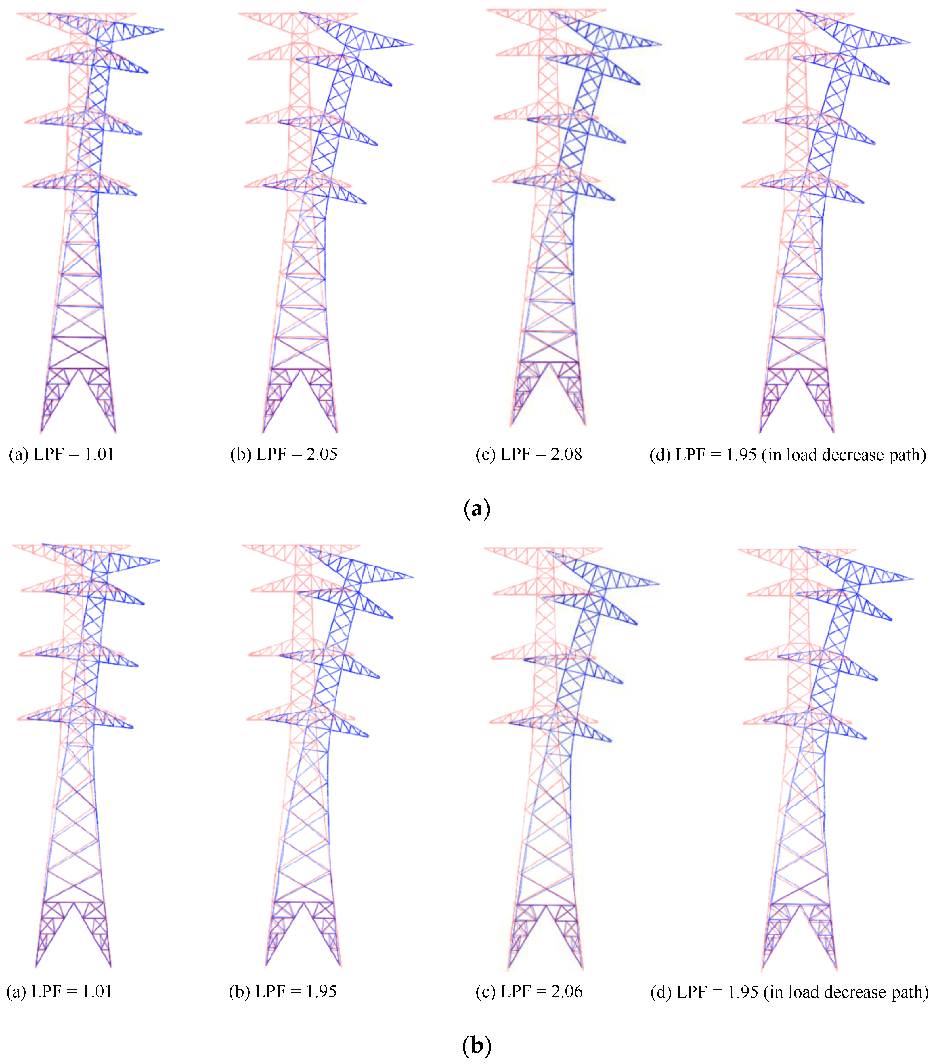
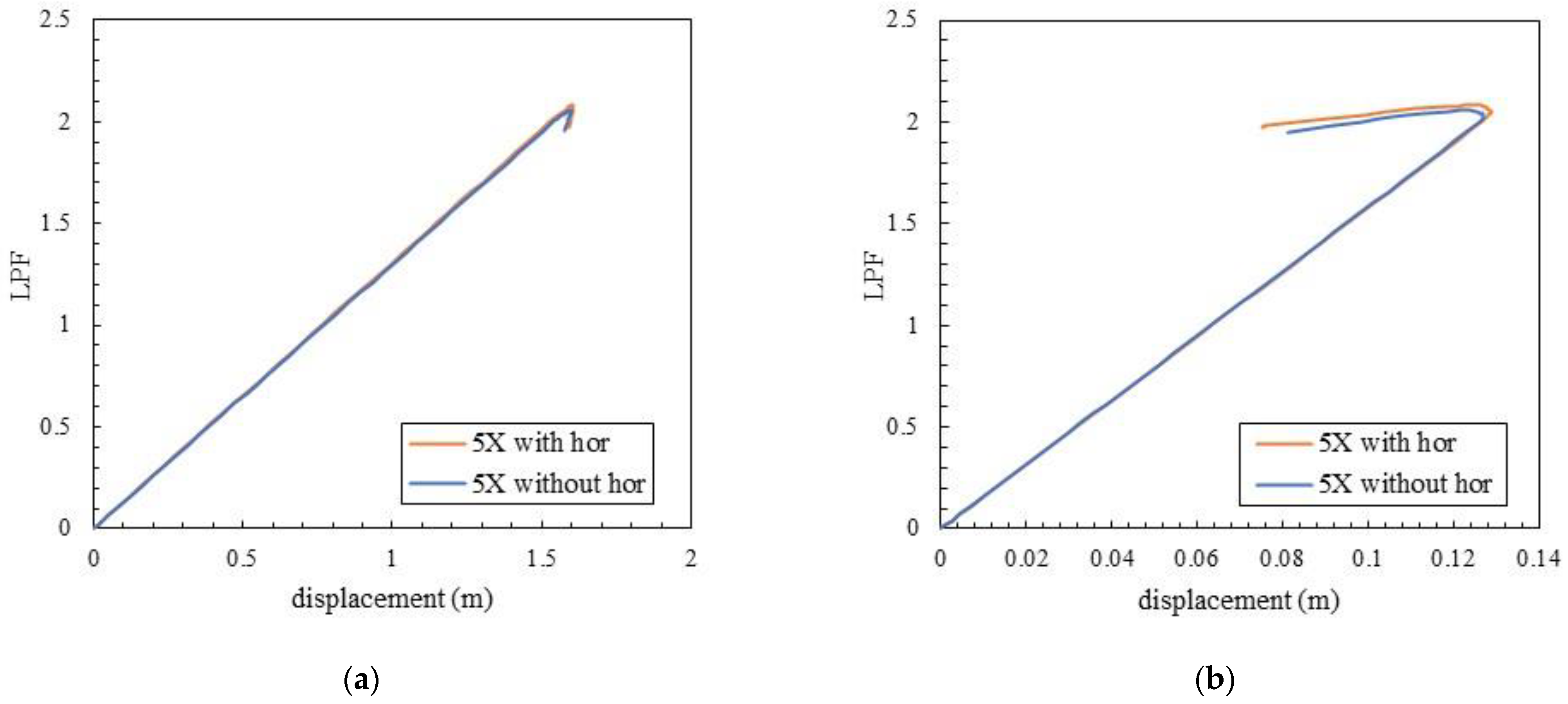
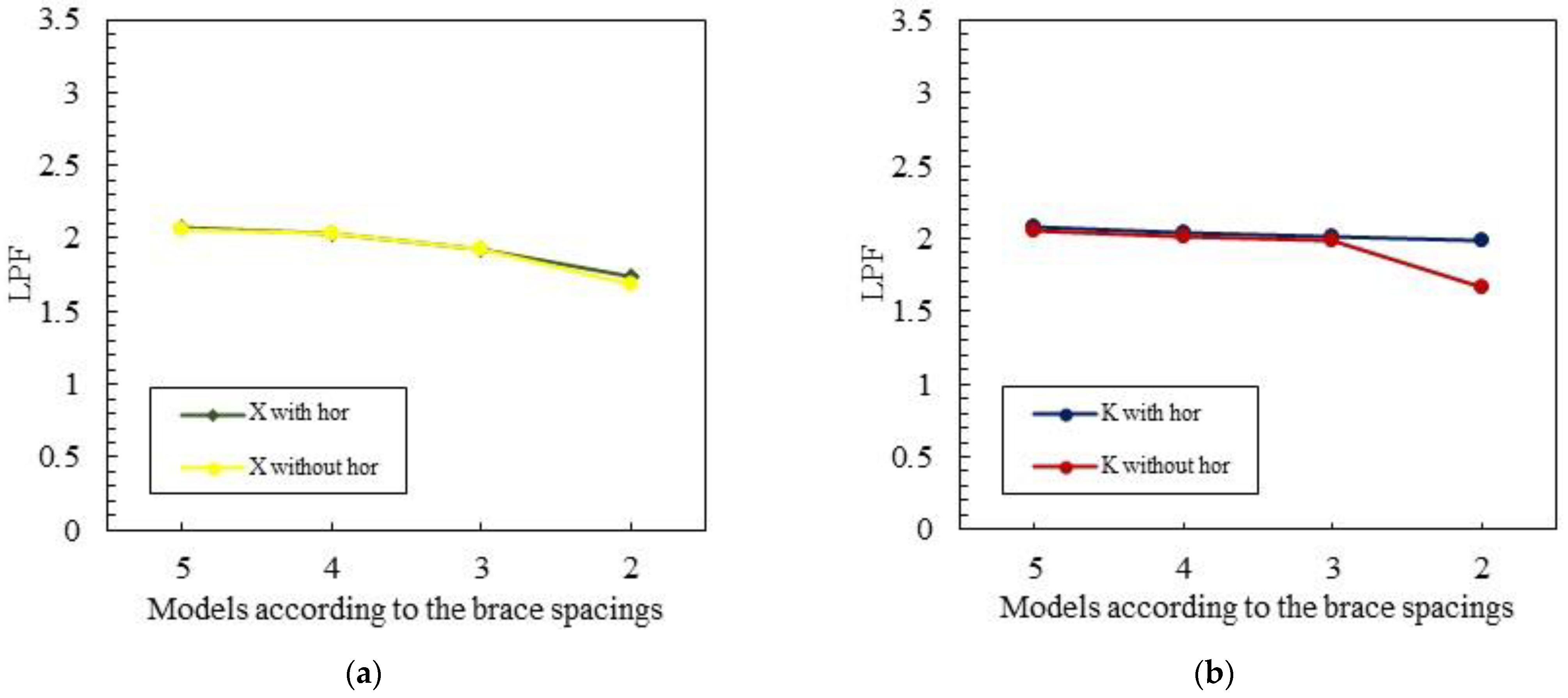
3.3. Effects of Secondary Members on Load-Carrying Capacity
4. Conclusions
Author Contributions
Funding
Data Availability Statement
Acknowledgments
Conflicts of Interest
References
- Xu, Y.L.; Lin, J.F.; Zhan, S.; Wang, F.Y. Multistage damage detection of a transmission tower: Numerical investigation and experimental validation. Struct. Control Health Monit. 2019, 26, e2366. [Google Scholar] [CrossRef]
- Mahamid, M.; Tasbahji, T.; Tort, C. Investigating Different Horizontal Bracing Schemes on the Deflection and Behavior of Latticed Steel Transmission Line Towers; Structures Congress: Orlando, FL, USA, 2019; pp. 299–308. [Google Scholar] [CrossRef]
- de Souza, R.R.; Miguel, L.F.F.; Kaminski, J., Jr.; Lopez, R.H. Topology design recommendations of transmission line towers to minimize the bolt slippage effect. Eng. Struct. 2019, 178, 286–297. [Google Scholar] [CrossRef]
- Bezas, M.-Z.; Jaspart, J.-P.; Vayas, I.; Demonceau, J.-F. Design recommendations for the stability of transmission steel lattice towers. Eng. Struct. 2022, 252, 113603. [Google Scholar] [CrossRef]
- Ebid, A.M.; El-Aghoury, M.A.; Onyelowe, K.C. Estimating the Optimum Weight for Latticed Power-Transmission Towers Using Different (AI) Techniques. Designs 2022, 6, 62. [Google Scholar] [CrossRef]
- American Society of Civil Engineers. ASCE Manual 74, Guidelines for Electrical Transmission Line Structural Loading, 4th ed.; ASCE: New York, NY, USA, 2020. [Google Scholar]
- Dreyer, W. Special Features in the Design of Transmission Tower Lines as Imposed by Electrical Conditions. Trans. Am. Inst. Electr. Eng. 1923, XLII, 962–966. [Google Scholar] [CrossRef]
- Taniwaki, K.; Ohkubo, S. Optimal synthesis method for transmission tower truss structures subjected to static and seismic loads. Struct. Multidiscip. Optim. 2004, 26, 441–454. [Google Scholar] [CrossRef]
- Kaminski, J.; Riera, J.; de Menezes, R.; Miguel, L.F. Model uncertainty in the assessment of transmission line towers subjected to cable rupture. Eng. Struct. 2008, 30, 2935–2944. [Google Scholar] [CrossRef]
- Ju, Y.-Z.; Xue, Q.-L.; Li, H. Failure Analysis of Transmission Tower under the Effect of Ice-Covered Power Transmission Line. In Proceedings of the 2009 First International Conference on Information Science and Engineering, Nanjing, China, 26–28 December 2009; pp. 4301–4304. [Google Scholar] [CrossRef]
- Zheng, H.-D.; Fan, J.; Long, X.-H. Analysis of the seismic collapse of a high-rise power transmission tower structure. J. Constr. Steel Res. 2017, 134, 180–193. [Google Scholar] [CrossRef]
- Cai, M.; Yang, X.; Huang, H.; Zhou, L. Investigation on Galloping of D-Shape Iced 6-Bundle Conductors in Transmission Tower Line. KSCE J. Civ. Eng. 2020, 24, 1799–1809. [Google Scholar] [CrossRef]
- Govindasamy, N.; Syamsir, A.; Mardi, N.H.; Malek, M.A. Effect of tsunami load by earthquake at manila trench on transmission tower. Ain Shams Eng. J. 2021, 12, 3593–3602. [Google Scholar] [CrossRef]
- Mahmoudi, A.; Nasrollahzadeh, K.; Jafari, M.A. Probabilistic failure analysis of 400 kV transmission tower-line system subjected to wind and ice hazards. Wind Struct. 2021, 33, 251–264. [Google Scholar]
- Savory, E.; Parke, G.A.; Zeinoddini, M.; Toy, N.; Disney, P. Modelling of tornado and microburst-induced wind loading and failure of a lattice transmission tower. Eng. Struct. 2001, 23, 365–375. [Google Scholar] [CrossRef]
- Shehata, A.; El Damatty, A.; Savory, E. Finite element modeling of transmission line under downburst wind loading. Finite Elements Anal. Des. 2005, 42, 71–89. [Google Scholar] [CrossRef]
- Zhang, Z.; Li, H.; Li, G.; Wang, W.; Tian, L. The Numerical Analysis of Transmission Tower-Line System Wind-Induced Collapsed Performance. Math. Probl. Eng. 2013, 2013, 413275. [Google Scholar] [CrossRef]
- Tian, L.; Zeng, Y. Parametric Study of Tuned Mass Dampers for Long Span Transmission Tower-Line System under Wind Loads. Shock. Vib. 2016, 2016, 4965056. [Google Scholar] [CrossRef]
- Tapia-Hernández, E.; Ibarra-González, S.; De-León-Escobedo, D. Collapse mechanisms of power towers under wind loading. Struct. Infrastruct. Eng. 2017, 13, 766–782. [Google Scholar] [CrossRef]
- Tian, L.; Pan, H.; Qui, C.; Ma, R.; Yu, Q. Wind-induced collapse analysis of long-span transmission tower-line system considering the member buckling effect. Adv. Struct. Eng. 2019, 22, 30–41. [Google Scholar] [CrossRef]
- Yang, X.; Lei, Y.; Liu, L.; Huang, J. Simulation of nonstationary wind in one-spatial dimension with time-varying coherence by wavenumber-frequency spectrum and application to transmission line. Struct. Eng. Mech. 2020, 75, 425–434. [Google Scholar]
- Tian, L.; Dong, X.; Pan, H.; Gao, G.; Xin, A. Critical seismic incidence angle of transmission tower based on shaking table tests. Struct. Eng. Mech. 2020, 76, 251–267. [Google Scholar]
- Tapia-Hernández, E.; De-León-Escobedo, D. Vulnerability of transmission towers under intense wind loads. Struct. Infrastruct. Eng. 2021, 18, 1235–1250. [Google Scholar] [CrossRef]
- Rao, N.P.; Knight, G.S.; Lakshmanan, N.; Iyer, N.R. Investigation of transmission line tower failures. Eng. Fail. Anal. 2010, 17, 1127–1141. [Google Scholar]
- Rao, N.P.; Knight, G.S.; Mohan, S.; Lakshmanan, N. Studies on failure of transmission line towers in testing. Eng. Struct. 2012, 35, 55–70. [Google Scholar]
- Zhang, Z.; Xie, Q. Failure analysis of transmission tower subjected to strong wind load. J. Constr. Steel Res. 2019, 160, 271–279. [Google Scholar] [CrossRef]
- Albermani, F.; Kitipornchai, S. Numerical simulation of structural behaviour of transmission towers. Thin-Walled Struct. 2003, 41, 167–177. [Google Scholar] [CrossRef]
- Albermani, F.; Mahendran, M.; Kitipornchai, S. Upgrading of transmission towers using a diaphragm bracing system. Eng. Struct. 2004, 26, 735–744. [Google Scholar] [CrossRef]
- Xie, Q.; Sun, L. Failure mechanism and retrofitting strategy of transmission tower structures under ice load. J. Constr. Steel Res. 2012, 74, 26–36. [Google Scholar] [CrossRef]
- Xie, Q.; Sun, L. Experimental Study on the Mechanical Behavior and Failure Mechanism of a Latticed Steel Transmission Tower. Eng. Struct. 2013, 139, 1009–1018. [Google Scholar] [CrossRef]
- Cai, Y.; Xie, Q.; Xue, S. Effects of additional diaphragms on the wind-resistant performance of power transmission tower. In Proceedings of the 2016 World Congress on Advances in Civil, Environmental, and Materials Research (ACEM16), Jeju Island, Republic of Korea, 28 August–1 September 2016. [Google Scholar]
- Chen, J.; Cao, S.; Xian, Q. Optimization Design of Transmission Tower Based on Intelligent Selection. IOP Conf. Ser. Mater. Sci. Eng. 2019, 473, 012035. [Google Scholar] [CrossRef]
- Meshmesha, H.M.; Kennedy, J.B.; Sennah, K.; Moradi, S. Static and dynamic analysis of guyed steel lattice towers. Struct. Eng. Mech. 2019, 69, 567–577. [Google Scholar]
- Sheppard, D.J.; Palmer, A.C. Optimal design of transmission towers by dynamic programming. Comput. Struct. 1972, 2, 455–468. [Google Scholar] [CrossRef]
- Natarajan, K.; Santhakumar, A. Reliability-based optimization of transmission line towers. Comput. Struct. 1995, 55, 387–403. [Google Scholar] [CrossRef]
- Mathakari, S.; Gardoni, P.; Agarwal, P.; Raich, A.; Haukaas, T. Reliability-Based Optimal Design of Electrical Transmission Towers Using Multi-Objective Genetic Algorithms. Comput. Civ. Infrastruct. Eng. 2007, 22, 282–292. [Google Scholar] [CrossRef]
- de Souza, R.R.; Fadel Miguel, L.F.; Lopez, R.H.; Miguel, L.F.F.; Torii, A.J. A procedure for the size, shape and topology optimization of transmission line tower structures. Eng. Struct. 2016, 111, 162–184. [Google Scholar] [CrossRef]
- Srihitha, S.; Rao, B.C.M. Analysis of transmission towers for optimal bracing configuration. J. Struct. Eng. 2016, 5, 1. [Google Scholar]
- Taheri, F.; Ghasemi, M.R.; Dizangian, B. Practical optimization of power transmission towers using the RBF-based ABC algorithm. Struct. Eng. Mech. 2020, 73, 463–479. [Google Scholar]
- Khodzhaiev, M.; Reuter, U. Optimization design of transmission tower based on intelligent selection. Eng. Struct. 2021, 240, 112306. [Google Scholar] [CrossRef]
- Grzywinski, M. Optimization of spatial truss towers based on Rao algorithms. Struct. Eng. Mech. 2022, 81, 367–378. [Google Scholar]
- American Society of Civil Engineers. Design of Latticed Steel Transmission Structure; ASCE: New York, NY, USA, 2015. [Google Scholar]
- Hamidreza, G. Effect of Joint Flexibility on the Nonlinear Static and Dynamic Behaviour of Offshore Jacket Platforms/Hamidreza Golabi. Ph.D. Thesis, University of Malaya, Kuala Lumpur, Malaysia, 2015. [Google Scholar]
- Al-Bermani, F.G.A.; Kitipornchai, S. Nonlinear Analysis of Thin-Walled Structures Using Least Element/Member. Eng. Struct. 1990, 116, 215–234. [Google Scholar] [CrossRef]
- Kroeker, D. Structural Analysis of Transmission Towers with Connection Slip Modeling. Master’s Thesis, University of Manitoba, Winnipeg, MB, Canada, 2000. [Google Scholar]
- Jeddi, A.B.; Shafieezadeh, A.; Hur, J.; Ha, J.; Hahm, D.; Kim, M. Multi-hazard typhoon and earthquake collapse fragility models for transmission towers: An active learning reliability approach using gradient boosting classifiers. Earthq. Eng. Struct. Dyn. 2022, 51, 3552–3573. [Google Scholar] [CrossRef]
- Uriz, P.; Filippou, F.C.; Mahin, S.A. Model for cyclic inelastic buckling of steel braces. J. Struct. Eng. 2008, 134, 619–628. [Google Scholar] [CrossRef]
- Darestani, Y.M.; Shafieezadeh, A.; Cha, K. Effect of modelling complexities on extreme wind hazard performance of steel lattice transmission towers. Struct. Infrastruct. Eng. 2020, 16, 898–915. [Google Scholar] [CrossRef]
- Wang, J.; Li, H.N.; Fu, X.; Li, Q. Geometric imperfections and ultimate capacity analysis of a steel lattice transmission tower. J. Constr. Steel Res. 2021, 183, 106734. [Google Scholar] [CrossRef]


| Member Type | Cross Section (mm × mm) |
|---|---|
| Main Post | Φ 609.6 × 16 Φ 609.6 × 14 Φ 558.8 × 14 Φ 558.8 × 12 Φ 457.0 × 12 Φ 406.0 × 10 Φ 318.5 × 8.0 Φ 216.3 × 7.0 Φ 165.2 × 5.5 |
| Brace | Φ 216.3 × 7.0 Φ 190.7 × 5.3 Φ 165.2 × 5.5 Φ 139.8 × 4.5 Φ 101.6 × 3.2 Φ 89.1 × 3.2 |
| Horizontal Member | Φ 216.3 × 7.0 Φ 190.7 × 5.3 Φ 165.2 × 5.5 Φ 139.8 × 4.5 Φ 89.1 × 3.2 Φ 76.3 × 2.8 |
| Cross Arm | L 600 × 40 L 650 × 60 L 700 × 60 L 750 × 60 L 800 × 60 L 900 × 60 L 900 × 70 L 1000 × 70 L 1200 × 80 L 1300 × 90 L 1300 × 120 L 1500 × 120 L 1750 × 120 L 1750 × 150 L 2000 × 150 L 2000 × 200 |
| Parameter | Conductor | Ground Wire |
|---|---|---|
| Specification | ACSR (cardinal) | AWS-200 |
| Rated tension strength (kN) | 150 | 126 |
| Unit weight (N/m) | 17.26 | 9.42 |
| Outer diameter (m) | 0.03 | 0.018 |
| Area (mm2) | 547.3 | 204.3 |
| Modulus of elasticity (GPa) | 74.2 | 108.8 |
| Thermal expansion coefficient (10–6/°C) | 23 | 15.5 |
| Analysis Flow | Analysis Type | Objective | Applied Load Case |
|---|---|---|---|
| 1 | Linear static analysis | To observe the torsional and distortional resistance effect | Broken wire case |
| 2 | Eigenvalue analysis | To observe the elastic buckling resistance effect | Wind load case |
| 3 | Geometric nonlinear and inelastic analysis | To observe the load-carrying-capacity effect | Wind load case |
| Panel | Height (m) | Kz | Cf | Wind Pressure (N/mm2) |
|---|---|---|---|---|
| 1 | 16.5 | 1.0 | 1.9 | 1438.1 |
| 2 | 26.5 | 1.2 | 1.8 | 1679.8 |
| 3 | 35.5 | 1.3 | 1.7 | 1765.6 |
| 4 | 42.5 | 1.3 | 1.7 | 1815.8 |
| 5 | 46 | 1.4 | 1.7 | 1839.1 |
| 6 | 52 | 1.4 | 1.7 | 1932.5 |
| 7 | 57.5 | 1.4 | 1.6 | 1862.9 |
| 8 | 63.5 | 1.5 | 1.6 | 1807.5 |
| 9 | 67.8 | 1.5 | 1.6 | 1858.6 |
| 10 | 71.9 | 1.5 | 1.6 | 1935.6 |
| 11 | 76.0 | 1.5 | 1.7 | 2045.7 |
| 12 | 80.0 | 1.5 | 1.6 | 1957.7 |
| 13 | 84.3 | 1.6 | 1.6 | 2002.6 |
| 14 | 88.4 | 1.6 | 1.7 | 2060.8 |
| 15 | 92.5 | 1.6 | 1.8 | 2234.7 |
| 16 | 96.5 | 1.6 | 1.7 | 2154.6 |
| 17 | 100.8 | 1.6 | 1.7 | 2210.3 |
| 18 | 103.3 | 1.6 | 1.7 | 2206.2 |
| 19 | 108.5 | 1.6 | 1.8 | 2349.9 |
| Conductor | Ground Wire | |
|---|---|---|
| V | 47,705 N | 6280 N |
| T | 86,827 N | 17,619 N |
| L | 324,043 N | 65,753 N |
| Spacing | X Brace | ||||||||||||||||
|---|---|---|---|---|---|---|---|---|---|---|---|---|---|---|---|---|---|
| Post 1 | Post 2 | Post 3 | Post 4 | ||||||||||||||
| Ux (mm) | Uy (mm) | Uz (mm) | Uθ (rad) | Ux (mm) | Uy (mm) | Uz (mm) | Uθ (rad) | Ux (mm) | Uy (mm) | Uz (mm) | Uθ (rad) | Ux (mm) | Uy (mm) | Uz (mm) | Uθ (rad) | ||
| Five | Lv1 | 8.8 | 6.3 | 0.4 | 0.001 | −3.4 | 6.6 | 4.5 | 0.001 | −3.6 | −6.1 | 0.8 | 0.001 | 9.0 | −5.8 | 4.9 | 0.001 |
| Lv2 | 13.5 | 9.6 | 0.6 | 0.002 | −0.2 | 10.2 | 6.6 | 0.001 | −0.6 | −4.5 | 1.2 | 0.000 | 14.0 | −3.9 | 7.2 | 0.001 | |
| Lv3 | 20.3 | 14.5 | 0.7 | 0.003 | 5.0 | 15.1 | 8.4 | 0.002 | 4.5 | −1.3 | 1.5 | 0.001 | 20.8 | −0.6 | 9.2 | 0.002 | |
| Lv4 | 29.8 | 21.5 | 0.7 | 0.005 | 12.1 | 22.1 | 9.8 | 0.003 | 11.6 | 3.2 | 1.8 | 0.002 | 30.4 | 3.9 | 10.8 | 0.004 | |
| Lv5 | 43.0 | 31.3 | 0.5 | 0.009 | 21.3 | 31.9 | 10.8 | 0.006 | 20.8 | 9.1 | 1.8 | 0.004 | 43.6 | 9.8 | 12.0 | 0.007 | |
| Lv6 | 60.1 | 44.4 | 0.07 | 0.015 | 33.2 | 44.5 | 11.1 | 0.011 | 33.2 | 17.8 | 1.7 | 0.008 | 60.2 | 17.9 | 12.5 | 0.013 | |
| Four | Lv1 | 8.7 | 6.2 | 0.4 | 0.001 | −3.3 | 6.6 | 4.5 | 0.001 | −3.6 | −6.2 | 0.8 | 0.001 | 9.1 | −5.7 | 4.9 | 0.001 |
| Lv2 | 14.8 | 10.5 | 0.6 | 0.002 | 1.0 | 11.3 | 7.1 | 0.001 | 0.4 | −3.9 | 1.3 | 0.000 | 15.5 | −3.1 | 7.7 | 0.002 | |
| Lv3 | 24.2 | 17.3 | 0.7 | 0.004 | 8.4 | 18.2 | 9.0 | 0.002 | 7.7 | 0.7 | 1.7 | 0.001 | 25.0 | 1.7 | 9.9 | 0.003 | |
| Lv4 | 39.5 | 28.6 | 0.5 | 0.008 | 18.2 | 29.4 | 10.5 | 0.005 | 17.5 | 6.7 | 1.8 | 0.003 | 40.3 | 7.6 | 11.7 | 0.006 | |
| Lv5 | 61.1 | 45.1 | 0.02 | 0.016 | 31.8 | 45.2 | 11.0 | 0.011 | 31.7 | 16.1 | 1.7 | 0.007 | 61.2 | 16.2 | 12.4 | 0.013 | |
| Three | Lv1 | 8.6 | 6.1 | 0.4 | 0.001 | −3.3 | 6.7 | 4.5 | 0.001 | −3.7 | −6.3 | 0.8 | 0.001 | 9.1 | −5.6 | 4.9 | 0.001 |
| Lv2 | 17.6 | 12.5 | 0.7 | 0.002 | 2.9 | 13.5 | 7.7 | 0.002 | 2.1 | −3.1 | 1.4 | 0.000 | 18.4 | −1.9 | 8.4 | 0.002 | |
| Lv3 | 34.2 | 24.6 | 0.6 | 0.006 | 13.7 | 25.7 | 10.0 | 0.004 | 12.9 | 3.3 | 1.7 | 0.002 | 35.1 | 4.4 | 11.0 | 0.005 | |
| Lv4 | 63.7 | 47.0 | 0.09 | 0.016 | 28.6 | 47.1 | 10.9 | 0.011 | 28.5 | 12.1 | 1.5 | 0.006 | 63.9 | 12.3 | 12.2 | 0.013 | |
| Two | Lv1 | 8.6 | 6.1 | 0.4 | 0.001 | −3.2 | 6.7 | 4.5 | 0.001 | −3.7 | −6.3 | 0.8 | 0.001 | 9.2 | −5.5 | 4.9 | 0.001 |
| Lv2 | 25.6 | 18.3 | 0.6 | 0.004 | 6.1 | 19.7 | 8.7 | 0.003 | 5.0 | −2.5 | 1.5 | 0.001 | 26.9 | −0.9 | 9.6 | 0.003 | |
| Lv3 | 73.2 | 53.8 | 0.46 | 0.019 | 19.2 | 54.0 | 10.7 | 0.012 | 19.1 | 0.2 | 1.1 | 0.004 | 73.4 | 0.3 | 11.9 | 0.015 | |
| Spacing | X Brace | ||||||||||||||||
|---|---|---|---|---|---|---|---|---|---|---|---|---|---|---|---|---|---|
| Post 1 | Post 2 | Post 3 | Post 4 | ||||||||||||||
| Ux (mm) | Uy (mm) | Uz (mm) | Uθ (rad) | Ux (mm) | Uy (mm) | Uz (mm) | Uθ (rad) | Ux (mm) | Uy (mm) | Uz (mm) | Uθ (rad) | Ux (mm) | Uy (mm) | Uz (mm) | Uθ (rad) | ||
| Five | Lv1 | 8.9 | 6.4 | 0.4 | 0.001 | −3.4 | 6.5 | 4.5 | 0.001 | −3.5 | −6.0 | 0.8 | 0.001 | 9.0 | −5.9 | 4.9 | 0.001 |
| Lv2 | 13.2 | 9.2 | 0.6 | 0.002 | 0.1 | 10.6 | 6.6 | 0.001 | −0.9 | −5.0 | 1.2 | 0.001 | 14.4 | −3.4 | 7.2 | 0.001 | |
| Lv3 | 20.2 | 14.3 | 0.7 | 0.003 | 5.1 | 15.2 | 8.4 | 0.002 | 4.4 | −1.4 | 1.6 | 0.001 | 21.1 | −0.4 | 9.2 | 0.002 | |
| Lv4 | 29.8 | 21.2 | 0.7 | 0.005 | 12.2 | 22.4 | 9.8 | 0.003 | 11.4 | 3.1 | 1.8 | 0.002 | 30.8 | 4.4 | 10.9 | 0.004 | |
| Lv5 | 42.4 | 30.5 | 0.5 | 0.009 | 22.1 | 32.8 | 10.8 | 0.006 | 20.2 | 8.4 | 1.9 | 0.004 | 44.8 | 11.0 | 12.0 | 0.008 | |
| Lv6 | 60.6 | 44.8 | 0.05 | 0.016 | 33.5 | 44.8 | 11.3 | 0.012 | 33.6 | 18.2 | 1.8 | 0.008 | 60.6 | 18.1 | 12.7 | 0.013 | |
| Four | Lv1 | 8.9 | 6.4 | 0.4 | 0.001 | −3.4 | 6.5 | 4.5 | 0.001 | −3.5 | −5.9 | 0.8 | 0.001 | 9.0 | −5.9 | 4.9 | 0.001 |
| Lv2 | 14.2 | 9.7 | 0.6 | 0.002 | 1.6 | 12.1 | 7.0 | 0.001 | −0.2 | −4.9 | 1.3 | 0.001 | 16.3 | −2.0 | 7.6 | 0.002 | |
| Lv3 | 24.4 | 17.4 | 0.7 | 0.004 | 8.4 | 18.2 | 9.2 | 0.002 | 7.8 | 0.9 | 1.7 | 0.001 | 25.2 | 1.9 | 10.1 | 0.003 | |
| Lv4 | 38.4 | 27.3 | 0.5 | 0.007 | 19.7 | 31.1 | 10.5 | 0.006 | 16.6 | 5.3 | 1.8 | 0.003 | 42.2 | 9.6 | 11.6 | 0.007 | |
| Lv5 | 61.8 | 45.7 | 0.01 | 0.016 | 32.4 | 45.7 | 11.3 | 0.012 | 32.4 | 16.7 | 1.7 | 0.008 | 61.9 | 16.6 | 12.7 | 0.013 | |
| Three | Lv1 | 8.8 | 6.3 | 0.4 | 0.001 | −3.4 | 6.5 | 4.5 | 0.001 | −3.6 | −6.0 | 0.8 | 0.001 | 9.0 | −5.8 | 4.9 | 0.001 |
| Lv2 | 16.6 | 11.2 | 0.6 | 0.002 | 3.8 | 14.8 | 7.6 | 0.002 | 1.3 | −4.4 | 1.4 | 0.001 | 19.6 | −0.3 | 8.3 | 0.002 | |
| Lv3 | 32.8 | 23.1 | 0.6 | 0.006 | 15.6 | 27.7 | 10.0 | 0.005 | 11.7 | 1.6 | 1.8 | 0.002 | 37.5 | 6.9 | 11.0 | 0.005 | |
| Lv4 | 64.9 | 47.9 | 0.1 | 0.017 | 29.7 | 48.0 | 11.2 | 0.012 | 29.7 | 13.1 | 1.6 | 0.007 | 65.0 | 13.1 | 12.6 | 0.014 | |
| Two | Lv1 | 8.9 | 6.4 | 0.4 | 0.001 | −3.4 | 6.4 | 4.6 | 0.001 | −3.4 | −5.8 | 0.8 | 0.001 | 8.9 | −5.9 | 4.9 | 0.001 |
| Lv2 | 21.4 | 13.4 | 0.6 | 0.003 | 10.6 | 25.4 | 8.3 | 0.003 | 1.5 | −8.1 | 1.4 | 0.001 | 32.3 | 5.7 | 9.0 | 0.004 | |
| Lv3 | 75.3 | 55.5 | 0.46 | 0.019 | 21.1 | 55.6 | 11.2 | 0.012 | 21.2 | 1.8 | 1.3 | 0.004 | 75.4 | 1.8 | 12.6 | 0.016 | |
| Spacing | K Brace | ||||||||||||||||
|---|---|---|---|---|---|---|---|---|---|---|---|---|---|---|---|---|---|
| Post 1 | Post 2 | Post 3 | Post 4 | ||||||||||||||
| Ux (mm) | Uy (mm) | Uz (mm) | Uθ (rad) | Ux (mm) | Uy (mm) | Uz (mm) | Uθ (rad) | Ux (mm) | Uy (mm) | Uz (mm) | Uθ (rad) | Ux (mm) | Uy (mm) | Uz (mm) | Uθ (rad) | ||
| Five | Lv1 | 8.3 | 5.9 | 0.4 | 0.001 | −3.0 | 6.1 | 4.5 | 0.001 | −3.1 | −5.5 | 0.8 | 0.001 | 8.5 | −5.3 | 4.8 | 0.001 |
| Lv2 | 13.2 | 9.4 | 0.6 | 0.002 | 0.1 | 9.7 | 6.6 | 0.001 | −0.1 | −3.9 | 1.2 | 0.000 | 13.4 | −3.6 | 7.2 | 0.001 | |
| Lv3 | 20.0 | 14.4 | 0.7 | 0.003 | 5.2 | 14.6 | 8.4 | 0.002 | 5.0 | −0.7 | 1.6 | 0.001 | 20.3 | −0.4 | 9.2 | 0.002 | |
| Lv4 | 29.7 | 21.4 | 0.7 | 0.005 | 12.2 | 21.8 | 9.8 | 0.003 | 11.9 | 3.6 | 1.8 | 0.002 | 30.0 | 4.0 | 10.9 | 0.004 | |
| Lv5 | 43.0 | 31.4 | 0.5 | 0.009 | 21.5 | 31.6 | 10.8 | 0.006 | 21.3 | 9.6 | 1.9 | 0.004 | 43.3 | 9.9 | 12.1 | 0.007 | |
| Lv6 | 61.1 | 45.1 | 0.02 | 0.016 | 32.8 | 44.9 | 11.2 | 0.011 | 33.0 | 17.3 | 1.7 | 0.008 | 61.1 | 17.1 | 12.6 | 0.013 | |
| Four | Lv1 | 8.3 | 5.9 | 0.4 | 0.001 | −3.0 | 6.1 | 4.5 | 0.001 | −3.1 | −5.5 | 0.8 | 0.001 | 8.5 | −5.3 | 4.8 | 0.001 |
| Lv2 | 14.6 | 10.5 | 0.6 | 0.002 | 1.2 | 10.7 | 7.1 | 0.001 | 1.0 | −3.2 | 1.3 | 0.000 | 14.9 | −2.9 | 7.8 | 0.002 | |
| Lv3 | 24.3 | 17.4 | 0.7 | 0.004 | 8.5 | 17.7 | 9.1 | 0.002 | 8.3 | 1.4 | 1.7 | 0.001 | 24.5 | 1.8 | 10.0 | 0.003 | |
| Lv4 | 39.7 | 28.8 | 0.5 | 0.008 | 18.5 | 29.1 | 10.6 | 0.005 | 18.3 | 7.4 | 1.8 | 0.003 | 39.9 | 7.7 | 11.8 | 0.006 | |
| Lv5 | 62.4 | 46.0 | 0.04 | 0.016 | 31.7 | 45.8 | 11.2 | 0.011 | 31.9 | 15.9 | 1.7 | 0.007 | 62.3 | 15.6 | 12.6 | 0.013 | |
| Three | Lv1 | 8.3 | 5.9 | 0.4 | 0.001 | −3.0 | 6.1 | 4.5 | 0.001 | −3.1 | −5.5 | 0.8 | 0.001 | 8.4 | −5.3 | 4.8 | 0.001 |
| Lv2 | 17.6 | 12.6 | 0.7 | 0.002 | 3.0 | 12.8 | 7.9 | 0.001 | 2.8 | −2.2 | 1.5 | 0.000 | 17.8 | −1.9 | 8.6 | 0.002 | |
| Lv3 | 35.0 | 25.3 | 0.6 | 0.006 | 13.8 | 25.5 | 10.2 | 0.004 | 13.6 | 3.9 | 1.8 | 0.002 | 35.2 | 4.1 | 11.3 | 0.005 | |
| Lv4 | 66.1 | 48.5 | 0.2 | 0.017 | 28.8 | 48.4 | 11.2 | 0.012 | 28.9 | 11.8 | 1.6 | 0.006 | 66.0 | 11.6 | 12.6 | 0.014 | |
| Two | Lv1 | 8.3 | 5.9 | 0.4 | 0.001 | −2.9 | 6.1 | 4.5 | 0.001 | −3.1 | −5.4 | 0.8 | 0.001 | 8.4 | −5.2 | 4.9 | 0.001 |
| Lv2 | 26.5 | 19.0 | 0.6 | 0.004 | 6.5 | 19.2 | 9.2 | 0.003 | 6.3 | −1.2 | 1.6 | 0.001 | 26.7 | −1.0 | 10.1 | 0.003 | |
| Lv3 | 77.4 | 56.4 | 0.6 | 0.020 | 20.5 | 56.3 | 11.3 | 0.012 | 20.6 | 0.1 | 1.2 | 0.004 | 77.3 | −0.1 | 12.6 | 0.016 | |
| Spacing | K Brace | ||||||||||||||||
|---|---|---|---|---|---|---|---|---|---|---|---|---|---|---|---|---|---|
| Post 1 | Post 2 | Post 3 | Post 4 | ||||||||||||||
| Ux (mm) | Uy (mm) | Uz (mm) | Uθ (rad) | Ux (mm) | Uy (mm) | Uz (mm) | Uθ (rad) | Ux (mm) | Uy (mm) | Uz (mm) | Uθ (rad) | Ux (mm) | Uy (mm) | Uz (mm) | Uθ (rad) | ||
| Five | Lv1 | 8.3 | 5.9 | 0.4 | 0.001 | −3.0 | 6.1 | 4.5 | 0.001 | −3.1 | −5.5 | 0.8 | 0.001 | 8.4 | −5.3 | 4.9 | 0.001 |
| Lv2 | 12.8 | 8.9 | 0.6 | 0.002 | 0.8 | 10.5 | 6.5 | 0.001 | −0.4 | −4.5 | 1.2 | 0.000 | 14.2 | −2.6 | 7.1 | 0.001 | |
| Lv3 | 20.0 | 14.2 | 0.7 | 0.003 | 5.6 | 14.8 | 8.4 | 0.002 | 5.1 | −0.5 | 1.6 | 0.001 | 20.5 | 0.1 | 9.2 | 0.002 | |
| Lv4 | 29.3 | 20.8 | 0.7 | 0.005 | 13.0 | 22.5 | 9.7 | 0.004 | 11.7 | 3.2 | 1.8 | 0.002 | 30.8 | 5.1 | 10.7 | 0.004 | |
| Lv5 | 42.5 | 30.8 | 0.5 | 0.009 | 22.7 | 32.4 | 10.7 | 0.006 | 21.3 | 9.6 | 1.9 | 0.004 | 44.2 | 11.4 | 11.9 | 0.007 | |
| Lv6 | 61.4 | 45.3 | 0.01 | 0.016 | 33.0 | 45.1 | 11.3 | 0.012 | 33.1 | 17.5 | 1.8 | 0.008 | 61.3 | 17.2 | 12.7 | 0.013 | |
| Four | Lv1 | 8.3 | 5.9 | 0.4 | 0.001 | −3.0 | 6.1 | 4.5 | 0.001 | −3.1 | −5.5 | 0.8 | 0.001 | 8.4 | −5.3 | 4.9 | 0.001 |
| Lv2 | 14.1 | 9.7 | 0.6 | 0.002 | 2.3 | 11.9 | 6.9 | 0.001 | 0.8 | −3.9 | 1.3 | 0.000 | 16.0 | −1.4 | 7.5 | 0.002 | |
| Lv3 | 24.4 | 17.3 | 0.7 | 0.004 | 9.1 | 18.6 | 9.0 | 0.003 | 8.0 | 1.0 | 1.7 | 0.001 | 25.6 | 2.5 | 9.9 | 0.003 | |
| Lv4 | 38.6 | 27.7 | 0.5 | 0.007 | 20.7 | 30.6 | 10.3 | 0.006 | 18.3 | 7.1 | 1.8 | 0.003 | 41.5 | 10.5 | 11.5 | 0.007 | |
| Lv5 | 62.8 | 46.2 | 0.04 | 0.016 | 31.9 | 46.0 | 11.3 | 0.012 | 32.1 | 16.0 | 1.7 | 0.007 | 62.6 | 15.8 | 12.7 | 0.013 | |
| Three | Lv1 | 8.3 | 6.0 | 0.4 | 0.001 | −3.0 | 6.1 | 4.5 | 0.001 | −3.1 | −5.4 | 0.8 | 0.001 | 8.4 | −5.3 | 4.9 | 0.001 |
| Lv2 | 16.6 | 11.1 | 0.6 | 0.002 | 5.2 | 15.2 | 7.4 | 0.002 | 2.3 | −3.6 | 1.4 | 0.000 | 20.1 | 1.0 | 8.1 | 0.002 | |
| Lv3 | 33.3 | 23.6 | 0.6 | 0.006 | 17.1 | 27.4 | 9.8 | 0.005 | 14.0 | 3.8 | 1.7 | 0.002 | 37.0 | 8.2 | 10.8 | 0.005 | |
| Lv4 | 66.4 | 48.7 | 0.19 | 0.017 | 28.9 | 48.6 | 11.3 | 0.012 | 29.1 | 11.9 | 1.6 | 0.006 | 66.3 | 11.7 | 12.7 | 0.014 | |
| Two | Lv1 | 8.3 | 6.0 | 0.4 | 0.001 | −3.0 | 6.1 | 4.5 | 0.001 | −3.1 | −5.4 | 0.8 | 0.001 | 8.4 | −5.3 | 4.9 | 0.001 |
| Lv2 | 23.2 | 14.9 | 0.5 | 0.003 | 14.3 | 25.9 | 7.7 | 0.004 | 5.9 | −3.9 | 1.4 | 0.001 | 33.0 | 8.8 | 8.4 | 0.004 | |
| Lv3 | 77.8 | 56.7 | 0.6 | 0.020 | 20.7 | 56.5 | 11.4 | 0.012 | 20.9 | 0.3 | 1.2 | 0.004 | 77.7 | 0.0 | 12.8 | 0.016 | |
| Details | Models with X Bracing | Models with K Bracing | ||
|---|---|---|---|---|
| With Horizontal Members | Without Horizontal Members | With Horizontal Members | Without Horizontal Members | |
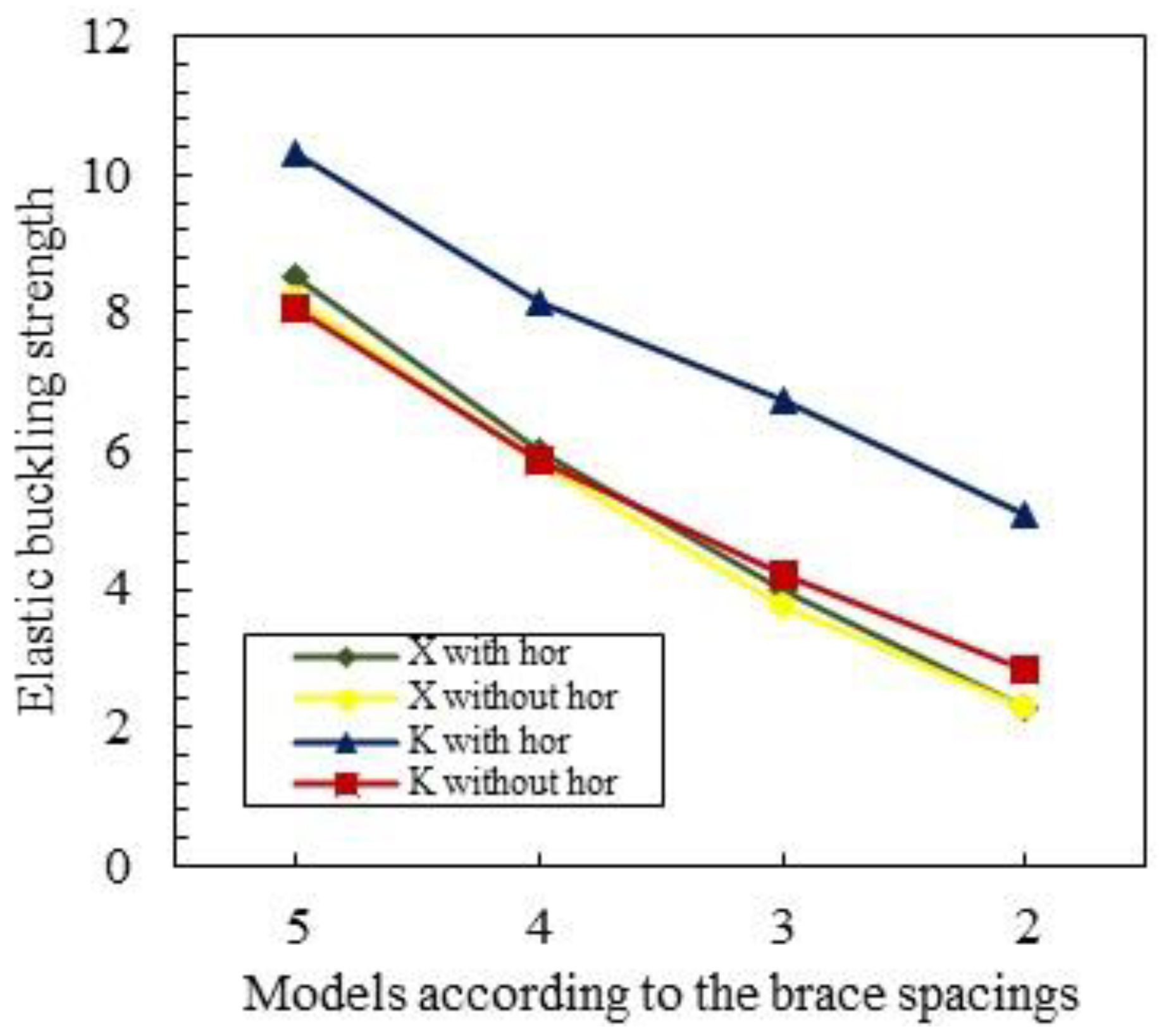
| Five equal brace spacings | 8.51 | 8.21 | 10.31 | 8.08 |
| Four equal brace spacings | 6.01 | 5.82 | 8.18 | 5.87 |
| Three equal brace spacings | 3.97 | 3.76 | 6.73 | 4.19 |
| Two equal brace spacings | 2.29 | 2.27 | 5.08 | 2.85 |
| Details | Models with X Bracing | Models with K Bracing | ||
|---|---|---|---|---|
| With Horizontal Members | Without Horizontal Members | With Horizontal Members | Without Horizontal Members | |
| Five equal brace spacings | 2.08 | 2.06 | 2.08 | 2.06 |
| Four equal brace spacings | 2.04 | 2.03 | 2.04 | 1.99 |
| Three equal brace spacings | 1.93 | 1.92 | 2.01 | 1.80 |
| Two equal brace spacings | 1.74 | 1.68 | 1.98 | 1.67 |
Disclaimer/Publisher’s Note: The statements, opinions and data contained in all publications are solely those of the individual author(s) and contributor(s) and not of MDPI and/or the editor(s). MDPI and/or the editor(s) disclaim responsibility for any injury to people or property resulting from any ideas, methods, instructions or products referred to in the content. |
© 2023 by the authors. Licensee MDPI, Basel, Switzerland. This article is an open access article distributed under the terms and conditions of the Creative Commons Attribution (CC BY) license (https://creativecommons.org/licenses/by/4.0/).
Share and Cite
Kim, P.; Han, W.S.; Kim, J.H.; Lee, J.; Kang, Y.J.; Kim, S. Analytical Investigation of the Effects of Secondary Structural Members on the Structural Behaviors of Transmission Towers. Buildings 2023, 13, 223. https://doi.org/10.3390/buildings13010223
Kim P, Han WS, Kim JH, Lee J, Kang YJ, Kim S. Analytical Investigation of the Effects of Secondary Structural Members on the Structural Behaviors of Transmission Towers. Buildings. 2023; 13(1):223. https://doi.org/10.3390/buildings13010223
Chicago/Turabian StyleKim, Pyounghwa, Whi Seok Han, Jeong Hun Kim, Jeonghwa Lee, Young Jong Kang, and Seungjun Kim. 2023. "Analytical Investigation of the Effects of Secondary Structural Members on the Structural Behaviors of Transmission Towers" Buildings 13, no. 1: 223. https://doi.org/10.3390/buildings13010223
APA StyleKim, P., Han, W. S., Kim, J. H., Lee, J., Kang, Y. J., & Kim, S. (2023). Analytical Investigation of the Effects of Secondary Structural Members on the Structural Behaviors of Transmission Towers. Buildings, 13(1), 223. https://doi.org/10.3390/buildings13010223