Article

Experimental and Numerical Study on Unreinforced Brick Masonry Walls Retrofitted with Sprayed Mortar under Uniaxial Compression

Department of Architectural Technology, Universitat Politècnica de Catalunya, 08028 Barcelona, Spain
*
Author to whom correspondence should be addressed.
Buildings 2023, 13(1), 122; https://doi.org/10.3390/buildings13010122
Submission received: 5 December 2022 / Revised: 28 December 2022 / Accepted: 30 December 2022 / Published: 3 January 2023

Abstract

:
The use of shotcrete or sprayed mortar is a common construction alternative to retrofit unreinforced brick masonry (URM), and extensive research has already been carried out in this area. However, most studies have been conducted on lateral strength, for example, eccentric compression or seismic forces. On the other hand, there are few studies about uniaxial compression, and the results of most studies confirm a strong relationship between the thickness of the retrofitting layer and whether it is a double-sided retrofitting section. However, most studies are exclusively experimental, with few samples, and lack numerical analysis; therefore, deeper research is required on this issue. In this sense, this paper combined experiments and finite element (FE) simulations to further study the uniaxial compression. A series of cyclic uniaxial compression experiments on URM retrofitting with sprayed mortar were performed. The experimental results were used to calibrate the FE model. Using these calibrated FE models, more variable parameters were run so that more reference results could be obtained. Moreover, the resulting damageable model of FE will be useful for studying the behavior in the inelastic phase. Results found that the compression strength of most composite walls retrofitted with sprayed mortar increases with the thickness of the sprayed layer and can improve the construction defects of the masonry itself. An over-thin sprayed layer reduces the range of the elastic phase of the composite wall. This phenomenon tends to stabilize with increasing thickness. The ultimate strength of the composite masonry is generally positively correlated with the overall increase in the thickness of the sprayed mortar but may cause a negative contribution to the ultimate strength of the composite masonry when the sprayed layer is too thin. The contribution of double-sided spraying to the ultimate strength of the composite wall was not as large as expected, but the contribution to the improvement of the elastic modulus of the wall was significant.

1. Introduction

An important part of the building stock in cities has centenary structures with resistances and safety less-than-satisfying compared to current standards. This fact is critical, for example, in the case of Spanish urban architecture of the 1950s, when thin brick structures were built due to an endemic shortage of dwellings in times of economic difficulties and the absence of construction standards. Thin walls may bring deficiencies in bending resistance, as well as inadequate load-bearing capacity. The current state of these buildings [1] makes the immediate renovation of these structures to recover their functionality and safety crucial. This is a global issue that, for example, the study by Fahimeh Yavartanoo et al. [2] investigated, focusing on various strengthening techniques used to enhance the resistance of URM structures to horizontal loads, and compare them. In addition, the loading situation of URM changes with renovations to the original building, such as building use changes, adding floors, and debilitating the walls.
One of the possible solutions is to spray cementitious materials on the walls, a technique with great potential, although, so far, this technique has had limited applications. At present, this spraying solution is mainly used in the construction and reinforcement of tunnels, retaining walls, and foundations. This technique uses machinery that combines water supplies, air, and components to sprayed them. This combination is performed dry or wet, depending on whether the solid materials, water, and pressure in the nozzle are mixed or if the dosed mortar and the additives in the nozzle are mixed, respectively [3,4]. In this study, the wet jet method was used, and this method was effective in reducing the rebound and significantly increasing the interface bond strength, and adding adequate additives to shotcrete or mortar, which promotes sufficient bond strength and setting time to obtain higher thicknesses in less time and avoid problems such as bounce and take-off. These ideas were confirmed by Malmgren, L. et al. [5] in their study of the rock-concrete interface. The study by Luiz Roberto et al. found that the addition of suitable additives could lead to an improvement in the consistency of the shotcrete and the ultimate strength [6]. This sprayed technique has obvious advantages, such as speed, quality, low need for construction process space, low impact in interior spaces, and high resistance in short terms, compared to other reinforcement alternatives. It also has limitations; for example, the aforementioned research project by Malmgren, L. et al. [5] pointed out that the shrinkage of shotcrete was probably causing the interface to separate before the concrete reached its supposed strength. In consequence, the sub-layer and shotcrete cannot form a composite. The main reason is the curing process shrinkage stress, which is greater than the interface bonding strength. In order to enhance the interfacial bond strength, the application of a bond agent at the interface is a common and proven method that this present research project uses. Kahn, L. et al. [7] studied the interface between shotcrete and brick using an interface agent in 1984. This study showed that a binder, such as epoxy needs to be applied or sprayed on the brick in order to form an adequate brick-concrete bond. Similar results were obtained by Beushausen, H. et al. [8] while studying the adhesion of concrete substrates.
Most studies in practical and research applications have focused on the use of shotcrete to improve the strength of URM to horizontal forces, such as earthquakes. Since masonry structures are not seismically resistant, many studies have shown that retrofitting the original structure with additional layers of shotcrete can improve its seismic resistance [9,10,11,12]. URM also improves the overall stiffness. In these retrofitting processes, the compression strength of masonry tends to increase as well. However, research studies have seldom analyzed this improvement, though it seems to be an obvious phenomenon. The common way to assess the URM reinforced by shotcrete or sprayed mortar is to directly add the compression strength of the sprayed layer to the original wall or to consider the sprayed layer thickness increased as part of the wall, which is obviously an inaccurate approach. In fact, the elastic phase of the composite wall will be very small, and in most cases, the composite wall is in an inelastic phase or an inelastic-elastic mixed phase because the composite wall has different parts of the material, which have its own material properties. This paper uses experimental results to calibrate the finite element (FE) model, and the calibrated FE model is used to simulate more different parameter conditions. This article studies the elastic phase and the behavior of the composite wall in the inelastic phase using an FE damageable model. The compression strength of a wall is often related to many factors, such as the slenderness ratio. A high slenderness ratio can make the wall eccentrically compressed or, with minor defects of its own, produce an out-of-plane bending moment and more likely to cause buckling, even if this moment is not very large [13]. To be able to study the compressive behavior of the masonry wall directly, small slenderness ratio samples will be used in this study to minimize the effect of eccentricity and to detect the lateral displacement used to determine whether there is significant out-of-plane bending. Figure 1 shows this method.

2. Sample Preparation

2.1. Masonry Samples

This research project prepared 15 masonry samples of 570 × 550 × 130 mm for compression tests with reference to EN1052-1. These 15 samples consisted of brick walls, which had a bonding agent and sprayed mortar. Since the differences in sample shapes were very small, the problems that may be posed by axial ratio were not determined. The dimensions of the clay bricks were 270 × 130 × 45 mm solid, with an average compressive strength of 50 MPa and porosity ≤ 25%, but were not weathered because these bricks had no external waterproof covering layer. Masonry mortar had a 1:5.5 mixing ratio, which is commonly used in local construction works. R32.5 cement (CEN II/B-L) and natural silica sand composed of 0.5–0.25 mm diameter were used. Table 1 details the specific mixture proportion, and the expected compressive strength was 7.5 MPa. The bonding agent was white latex formulated with polymers in aqueous dispersion called Primfix from Fixcer, with 8.5 and 38 MPa flexural strength and compression strengths, respectively, and pH 9. The sprayed mortar had a 1:4.7 mixing ratio, which is commonly used in local building works. R42.5 cement (CEN II/A-L) and natural silica sand composed of 0–5 mm diameter. Enapolymer 837, a plasticizer from ENAH, and Enahplast 42, a multifunctional additive, were used for the spraying mortar. The plasticizer increases the early strength of mortar and early bond strength. The multifunctional additive enhances the fluidity of the mortar and facilitates the spraying construction process. Table 1. presents the specific composition. The expected strength was 40 MPa.
The 15 masonry samples were reinforced with sprayed mortar with different thicknesses. According to these different thicknesses of the sprayed layer, the samples are divided into five main groups. Group 1 is the control group, which are masonry walls without sprayed layer, and groups 2 to 4 are the test groups, where the thicknesses of the single-sided sprayed layer range from 30 mm to 50 mm. Group 5 is the test group with the double-sided sprayed layer, which has a 30 mm thickness for both sides. Table 2 summarizes the main characteristics of these five sample groups.
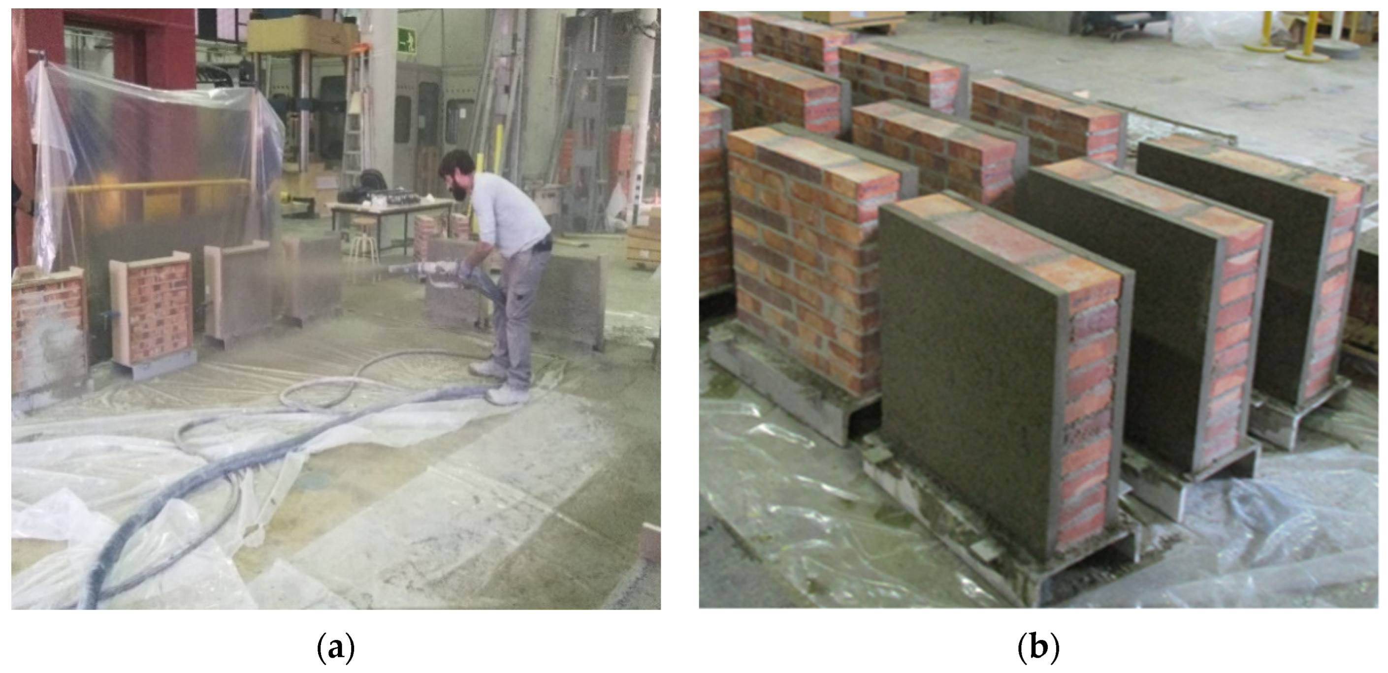
These 15 masonry walls were constructed by professional masons in the laboratory. They have the same masonry wall geometry and pattern, which follow EN1052 [14]. Brick walls were cured in a controlled environment with 95% humidity for 7 days before spraying the mortar on them. Using the method of layer-by-layer spraying, the spraying distance is about 1 m, and the pressure is about 0.15 mPa. The curing process lasted 28 days and was conducted indoors, with a controlled environment of 98% humidity and 21 degrees temperature. Figure 2 depicts these 15 sample cases and their spraying process [14].

2.2. Mechanical Property Test Samples

To be able to perform numerical simulations, it was also necessary to obtain basic mechanical property data from the material used in the test, so three types of test samples were defined: (1) sprayed mortar cylindrical samples, (2) sprayed mortar cuboid samples and (3) masonry mortar cuboid samples. Table 3 summarizes the main characteristics of these sample types, which followed EN12390. The first type of samples were 75 mm diameter cylinders of sprayed mortar, which were obtained using a drilling coring machine to a sprayed mortar block. The spraying preparation of this block strictly followed the same procedures used for the masonry wall samples, Then cured in 98% humidity and 21 degrees temperature indoors environment for 28 days. The second and third types of samples were mortar cuboids prepared following EN1015 and EN12390-5 [15,16]. They were built by pouring mortar in rectangular parallel-piped 40 × 40 × 160 mm steel molds, Then cured in 98% humidity and 21 degrees temperature indoors environment for 28 days.

3. Experimentation

3.1. Masonry Compression Tests

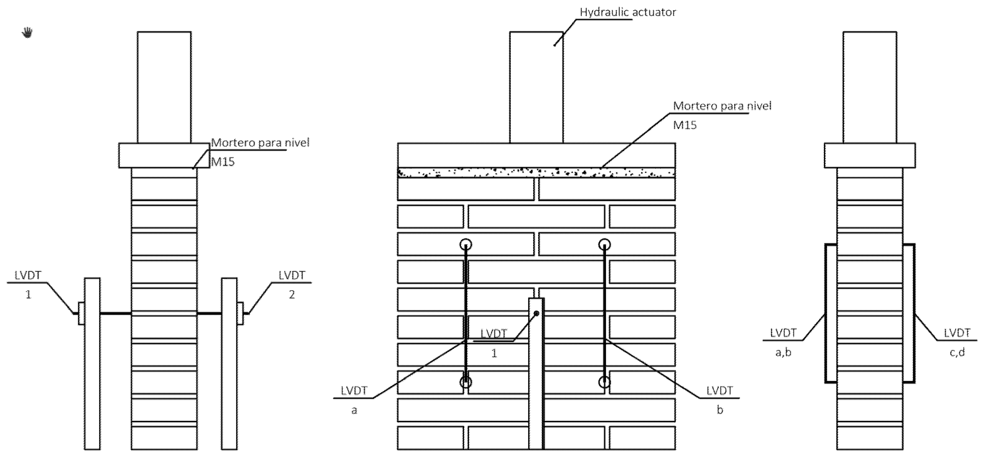
The employed test method mainly followed EN1052-1 [14]. Experiments were carried out at the UPC laboratory LATEM in 2021 using the machine, which consists of a load frame with a load cell of 4.7 MN, a dynamic actuator with a maximum capacity of 1000 kN in compression, and 650 kN in tension. The load application was controlled by servo valves both for compression and tension loads. In addition, three linear variable differential transformers (LVDTs) Temposonics ER, with stroke lengths of 50–150 mm, were set up on each side of the sample to monitor displacement in the vertical and normal directions. Figure 3 details the distribution of these six LVDTs, where LVDT1 and 2 detected out-of-plane displacements.
The load cell had a circular shaped bearing end that did not correspond to the cross-section of the sample. Therefore, a steel bearing with a thickness of 30 mm and a wooden plate with a thickness of 10 mm were used to carry the load evenly. To remove the adverse effect of the shape bearing, a preload of 10 kN was applied to the sample before testing the load.
These test load procedures had two main parts. Stage 1 consisted of loading and unloading cycles to obtain data for the measurement of Young’s modulus of the specimen. Stage 2 aimed to research the specimen’s ultimate capacity. Table 4 summarizes the procedure followed for these tests. This procedure is based on EN1052-1 and the former research projects [14,17,18,19]. Stage 1 had three identical loading-unloading cycles with an initial lower hold of 10 kN and an intermediate higher hold. Table 4 presents these cycles and holds loads, duration, and rates. Loads were a percentage of the maximum estimated load P0. This load was obtained using the compressive strength of the masonry wall, directly added to the compressive strength of the sprayed layer [20].

3.2. Mechanical Property Tests

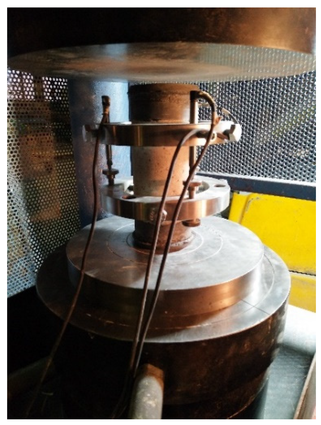
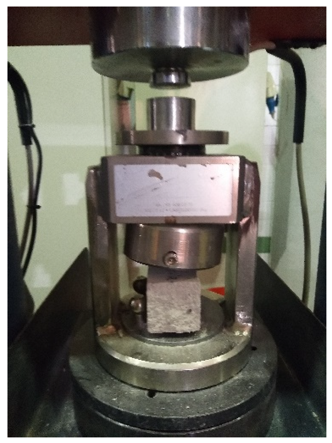
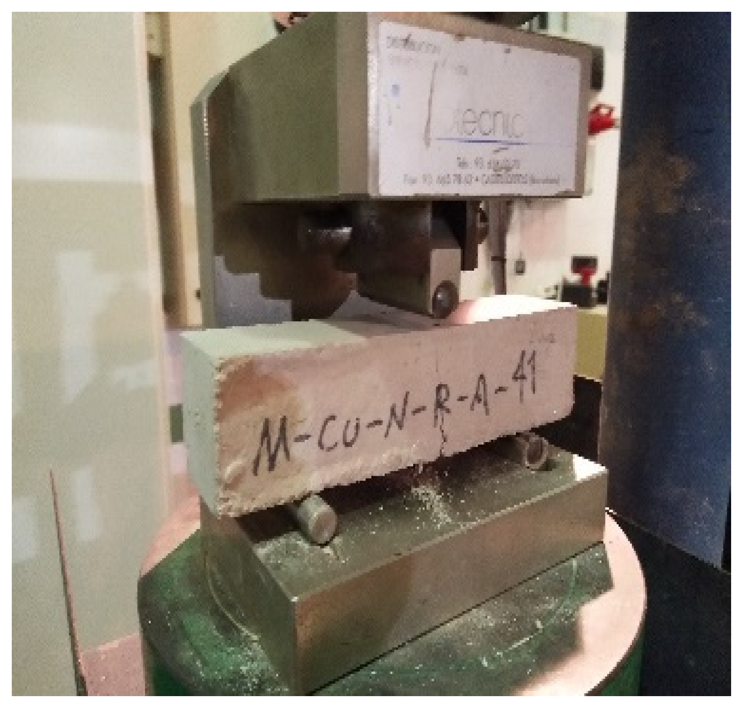
The Elastic modulus tests followed the European standards EN 12390-13 [21] using a servo-controlled machine with a maximum load capacity of 200 kN to apply the loading protocol to the sample. Three LVDTs with a range of 5 mm were fixed uniformly on the perimeter of the cylindrical sample section using a special fixture, as shown in Figure 4. They were used to monitor and record the deformation of the material during the test. The loading protocol was divided into two phases, first was the modulus of the elasticity test phase, where three load cycles with a peak value of 40 kN (approximately 0.3 times concrete compressive strength (fc)) were repeatedly applied, with a 20 s load hold between each load cycle. The second phase was the failure test, which completed the third load cycle when the machine continued applying load until the sample was destroyed. Both loading and unloading rates were 1 mm/min. The tests of compressive and flexural strength were carried out according to European standards EN12390-3 and EN12390-5 [15,22] and used servo-controlled machines with a maximum load capacity of 20 kN. The compressive and flexural tests were performed using the same sample. The sequence was to place a 40 × 40 × 160 mm rectangular sample on a bending standard test bench, load it to destruction until two separated rectangular samples were obtained, and then use these two samples for pressure testing. Figure 5 and Figure 6 show this sequence. The distance between the supports of the flexural test bench was 100 mm, and the loading point to the two sides of the support was 50 mm.

4. Experimentation Result

4.1. Mechanical Property Tests Results

Testing the mortar modulus of elasticity was performed according to method B in EN12390 part 13 [22]. Three samples were successfully tested that were smcsma2 to smcsma4. The secant modulus of elasticity (E) was calculated according to the method provided by Equation (1).
E s = σ a σ p ε a , 3 ε p , 2
where E s is secant modulus of elasticity of sprayed mortar; σ a is one-third of the maximum stress value; σ p is preload stress; ε a , 3 is strain at σ a on loading cycle 3; ε p , 2 is the strain at preload stress on loading cycle 2.
According to this calculation, the average ultimate strength is 30.13 MPa, and the average modulus is 22,706.62 MPa. Table 5 presents the detailed results.
Three samples of sprayed mortars and three samples of masonry mortar were successfully tested according to the method in parts three and five of EN12390 [15,22] and the previously described test method. The sample’s cubic compressive f c and flexural strengths f c f were counted using the method provided by Equations (2) and (3) as follows. Table 6 shows the detailed results.
f c = F A c
f c f = 3 × F × l 2 × d 1 × d 2
where f c f is flexural strength (MPa); f c is compression strength (MPa); A c is the area of the sample cross-section; F is the maximum load; l is the distance from the roller to the support; d 1 and d 2 is the length of two sides of the sample cross-section.

4.2. Masonry Test Results

All 15 samples–five groups of three samples–were successfully tested following the previously described experimental method and according to EN1052 [9]. No significant out-of-plane displacement was detected before the sample reached its peak load, which indicates that the effect of small eccentricity on the experiment is negligible. After the load value exceeds the peak, some LVDT inevitably fell off due to the peeling of the bonding material and the damage to the masonry material. Therefore, data recorded by the LVDT were mainly used for the phase before the peak load. Table 7 shows the complete results, and their calculation is shown in the following equation calculated according to Equations (4) and (5) from EN1052 [9] as follows:
E s m = F i , m a x 3 × ε i × A i
σ m , u = F i , m a x A i
where σ m , u is compressive strength); A i is the area of the sample cross-section; ε i is strains at stress equal to one-third of the maximum stress achieved.
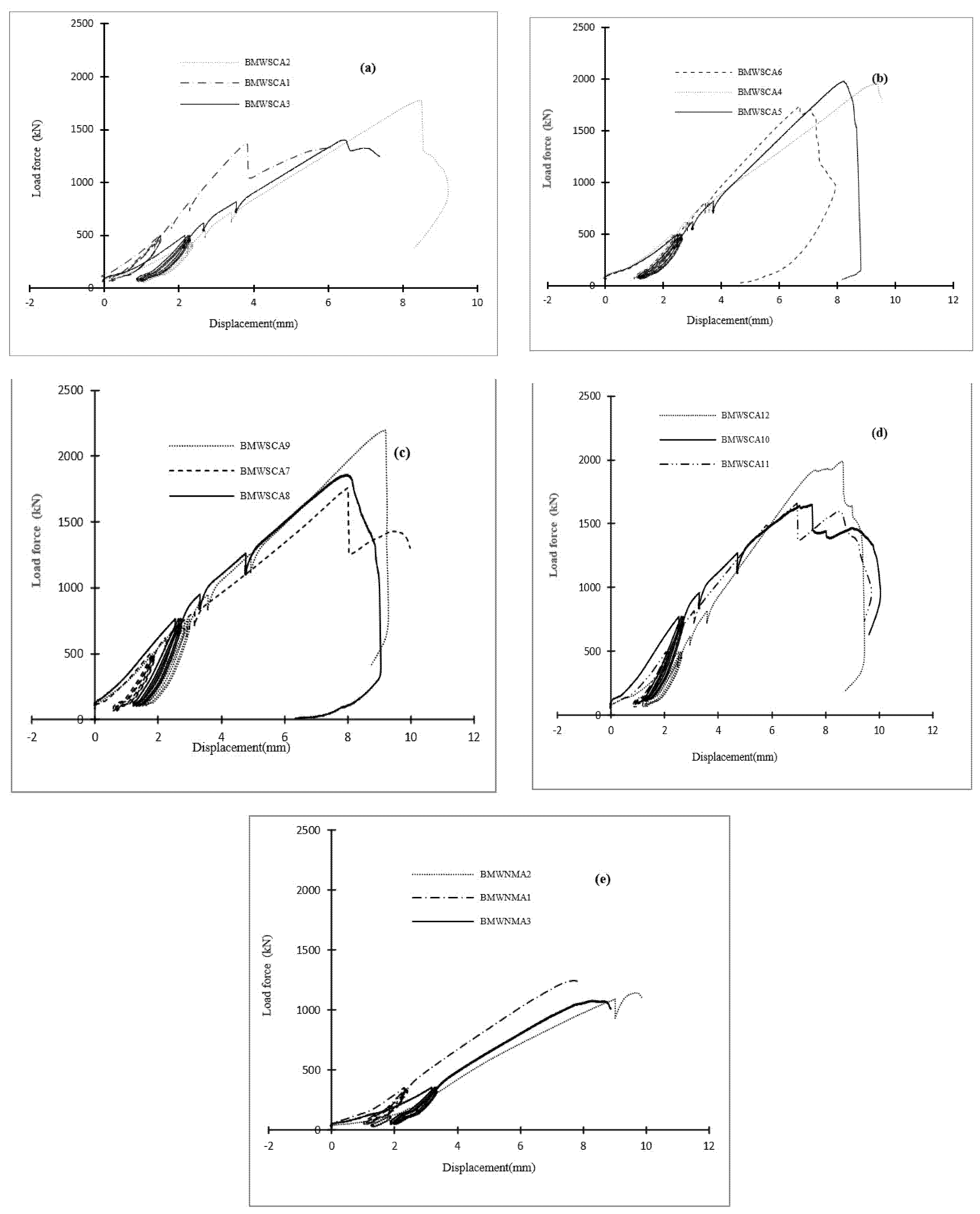
To visualize the test results, Figure 7 presents a set of force-displacement curves, from which one can observe that the composite wall retrofit with sprayed mortar makes the load-bearing capacity increase obvious, and the thickness of the sprayed mortar layer and the peak value are also positively correlated. In addition, the peak loads of the samples in group 5 did not meet expectations. In fact, the average level of their peak loads was between groups 2 and 3. However, the double-sided reinforced samples showed a strain-hardening-like behavior after the peak, which indicates good toughness and good energy dissipation performance.
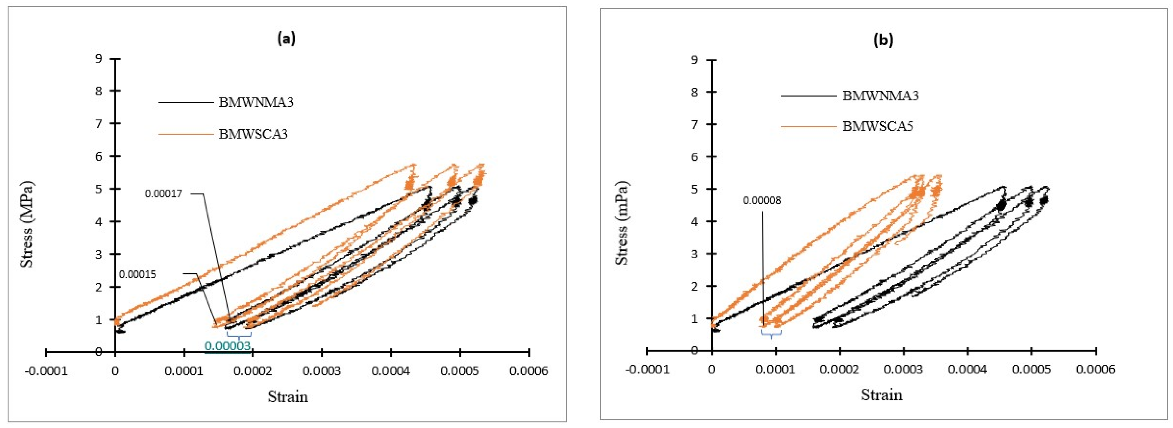
These experiments were designed for cyclic loading to obtain a more accurate modulus of elasticity and to study damage and plastic deformation. Figure 8 presents the series of stress-strain curves showing the cyclic loading phase. The graphs show the typical samples from each group to show damage and plastic deformation. A reduction in plastic deformation and damage to the wall by reinforcement can be seen. It can be observed from Figure 8a that the strain of BMNWMA3 is 0.00017 after the unloading of the first loading cycle, while the strain in the BMWSCA3-which is a composite wall with a 30 mm spray thickness-is 0.00015 in the same cycle. However, when the spray thickness reaches 40 mm or more, as shown in Figure 8b, this value is reduced to half of the former. It is possible that the cause of the strain in the masonry wall in the first cycle is twice that of the composite wall due to a construction defect in the masonry wall itself, which is clearly improved by the sprayed layer.
It can also be found that the strain difference, i.e., the damaging strain, between the first and second cycle is maintained around 0.00003 for all samples of the sprayed thickness. This may indicate that after the masonry wall’s own defects have been overcome. The sprayed layer is not particularly helpful in improving damage control.

4.3. Failure Modes

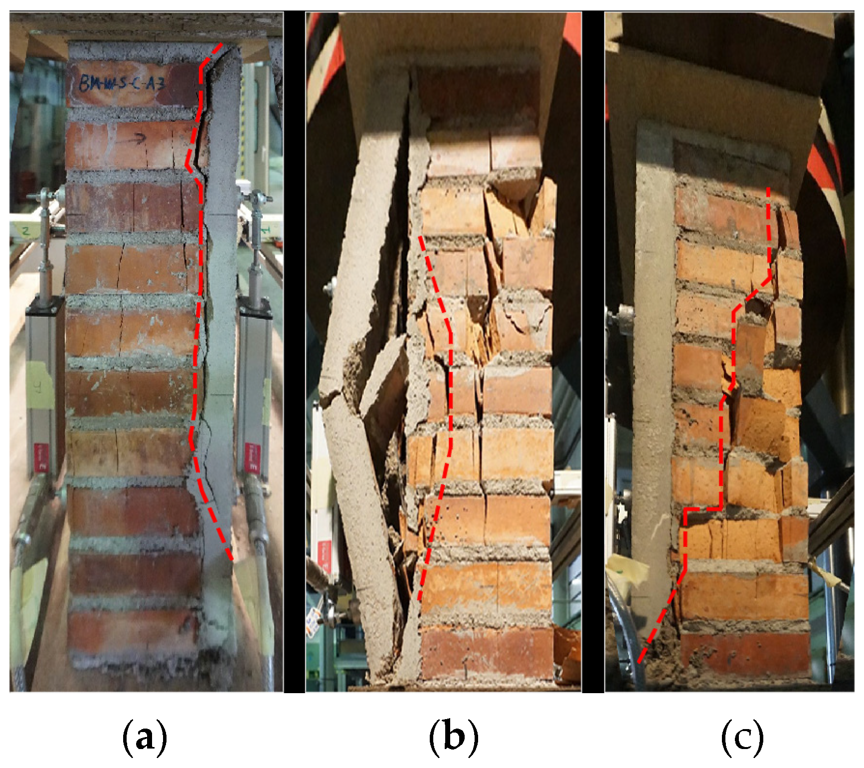
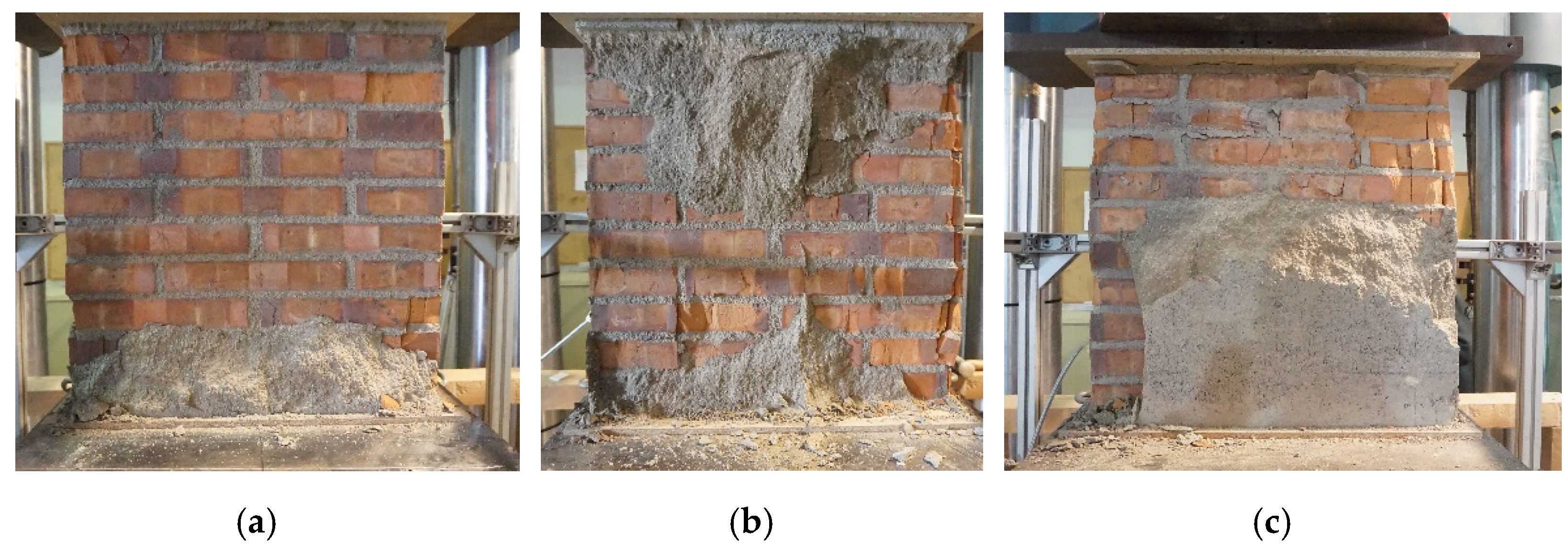
Almost all masonry wall samples showed nothing but vertical cracking, which is consistent with many previous studies. Page’s research [23] concluded that the typical cracking of brick walls under double-sided compression is along the vertical direction. Thamboo’s study [24] on concrete blocks and Olivera’s research [25] on masonry indicate that vertical cracking arises from the masonry mortar, having a greater deformation capacity in bricks. There were three typical failure modes observed from the lateral side, which are shown in Figure 9a–c.
Mode I: progressive damage occurs at the top and bottom of the interface during loading, and cracks appear on the non-sprayed side of the brick wall, with these cracks mainly concentrated in the upper half. During load peaks, the sprayed layer separates on the brick close to the interface, and the sample loses its load-bearing capacity. Mode II: during loading, progressive damage occurs at the top and bottom of the interface. The bricks appear damaged on the side without being sprayed and closed to the interface when the load is close to the peak. At the load, the sprayed layer breaks in the middle section, and the sample loses its load-carrying capacity. Mode III: during loading, cracks appear gradually along the diagonal side of the masonry wall, often uniformly. At the peak of the load, the whole separated along the crack direction, but not the interface. A similar mode of failure was observed in the masonry study [25].
There are also three typical failure modes observed from the frontal interface, which are shown in Figure 10a–c:
Mode A: very little of the lower part of the sprayed layer is bonded to the brick wall, while the top part falls off. Mode B: the bottom half of the sprayed layer is bonded to the brick wall, while the top part comes off. Mode C: the sprayed layer is partially bonded to the brick wall at the top and bottom, showing an X pattern. Most samples followed Mode I and Mode A, which means that most samples failed at the interface. Furthermore, the left and right sides of these samples tended to follow different failure modes. Among them, both BMWSCA6 and BMWSCA11 followed Mode III, meaning that they showed overall crack damage along their lateral diagonal but not their interface. BMWSCA10-12–samples with both sides sprayed–all have different damage patterns on both front and back sides, for all samples produced a sound during the test due to failure. This may indicate that the structure had a second load-bearing capacity after the first failure, and this can be corroborated with the curves of Figure 7b,d, where these two samples show a double peak or stress plateau during the final stage, and the two-peak values are relatively close. Table 8 depicts the failure modes of all samples.

5. Finite Elements Analysis and Calibration

To obtain more results to support the researchers’ analysis, this research project used the Abaqus software tool to build calibration finite element (FE) models to fit the test results in the experimental control group. Then the project used the calibrated models to simulate the load-bearing capacity of the sprayed mortar composite with different thicknesses.

5.1. Models

Therefore, these FE models were divided into calibration and test models. These models were first calibrated by testing the resultant data from the tests. The calibration models were single-sided sprayed walls 0, 30, 40, and 50 mm single-sided composite walls, which were CM1, CM2, CM3, and CM4, respectively, which were used to correspond to the sample group 1 to group 4 in the experiment. The purpose was to ensure that these models would approximately fit the test results with parameters calibrated. The test models were used to extend the test results. These models were single-sided sprayed walls with 10, 20, 60, 70, 90, 110, and 130 mm of thickness sprayed mortar, which was M1, M2, M3, M4, M5, M6, and M7, respectively. Parameters calibrated were used as models for testing the ultimate strength and failure modes. Table 9 shows the details of these models.

5.2. Materials Setup

According to the user manual of the software tool [26], the materials for the different walls’ parts were set individually, which were brick, masonry mortar, and spray mortar. To be able to simulate accurately, concrete plastic damage (CDP) is used in the material settings. CDP is a functional model used in the finite element simulation Abaqus software to simulate the nonlinear behavior of material damage, which can be run under an Explicit and Implicit mode. This plastic damage model was first proposed by Lubliner’s research group [27]. It has since been widely used in engineering simulations. For example, the CDP model was used by the Wang group [28] in their study of conventional clay brick masonry, by the Wang research team [29] in their study of brick masonry with boundary columns, and by Bolhossian’s group [30] in their study of grouted masonry. A similar approach was used in the study of historic masonry structures by Funari, M. et al. [31]. Most parameters in the material settings are derived from test results or related references [28,29,30,31], which are summarized in Table 10. The CDP parameters are summarized in Table 11, where spray mortars and masonry mortars data are derived from experimental results. As the mechanical properties of the bricks were not tested in this study, these data came from the study of clay brick masonry by Kaushik’s team research [32] and the dynamic study of clay brick by Hao’s research group study [33].

5.3. Solver, Interaction, and Mesh Setup

The solver method used is Abaqus Explicit, which is a suitable method for high-speed dynamics problems and highly nonlinear problems in which inertial forces play a role according to the characterization, and nonequilibrium forces propagate between neighboring cells as stress waves. The stability time increments of the explicit solver are generally small. When using Abaqus Explicit to simulate quasi-static problems, huge time increments are generally required if calculated with natural time periods. To rationalize the simulation process, the step time was set to 0.1 s, and the lowest frequency of the model was 180 Hz. A smoothing analysis step is used. To avoid the influence of inertial forces, the kinetic energy of material deformation or damage cannot exceed 10% of the internal energy, as similarly considered in former studies by Karapitta et al. and Dhanasekar et al. [34,35].
According to the observation of the failure mode, most of the separation occurs in the brick section. Furthermore, the authors tested the interfacial strength at the same time as this experiment, though these results will be analyzed and presented in future works. A special study considering the interface behavior is expected to be conducted later in conjunction with this paper. So, although it may have been considered that the interface will have an effect on the results, in this work, the interaction method between them is set to tie. The element type is C3D8R, with an original size of 5 × 5 mm in the mortar gap and 8 × 8 mm in the rest of the element. The boundary conditions are embedded at the top and bottom, and a vertical displacement with a total travel of 2.5 mm is applied to the upper part of the model.

5.4. Calibration

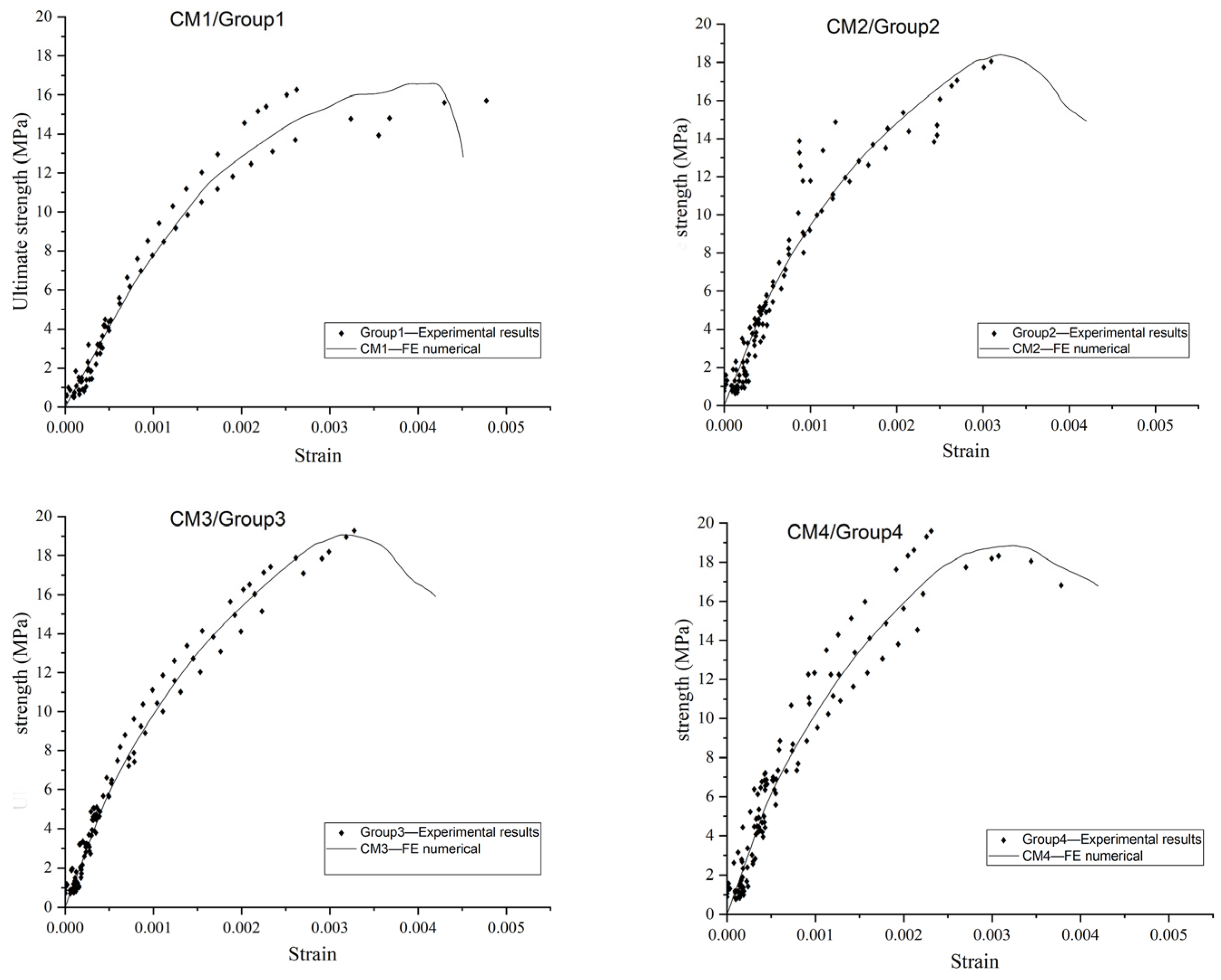
First, the kinetic energy of the model was about 1% of the internal energy, so this model could be considered a quasi-static type. In addition, this model records the stress-strain curve of the calibrated model and compares it with the experimental results. The outcomes show that the simulation results fit well with the experimental results. Figure 11 shows a comparison between these simulated and experimental results. In addition, the ultimate strength and modulus of elasticity of each model were counted and compared with the experimental results, as Table 12 details.
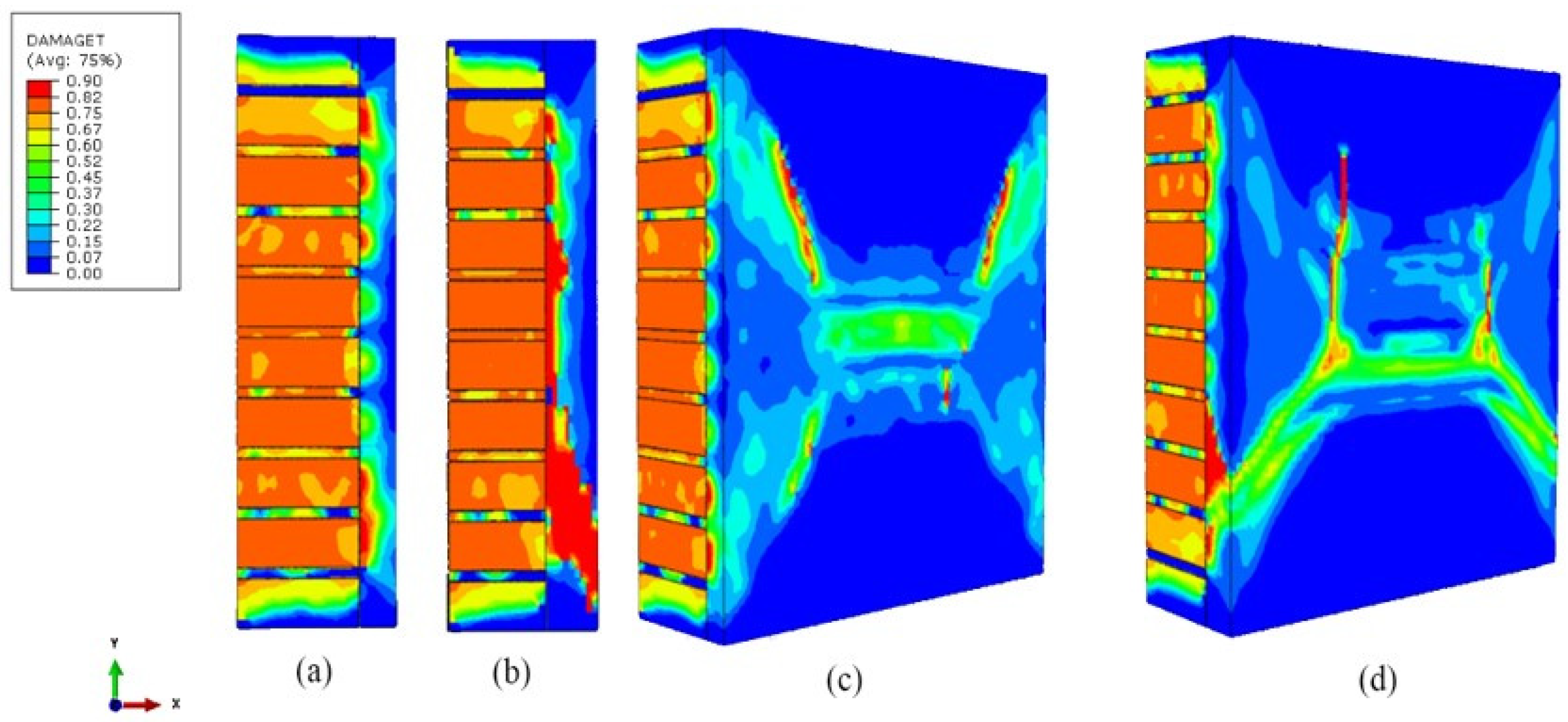
Due to the use of the CDP model, several typical damages were observed in FE results. The damages observed on the sides of the simulated results, shown in Figure 12a,b, were similar to the failure modes II and I, respectively, that had been observed in the experiments. On the front side, the damages from the simulated results were similar to the failure modes B and C, respectively, also observed in the experiment, as shown in Figure 12c,d.

6. Results and Discussion

6.1. Elastic Modulus

The method used to describe the behavior of composite masonry in the compact elastic phase is explained as follows. Since masonry is a composite material, according to the basic content of Hooke’s law of elasticity and the nature of composite mechanics [36], assuming that the strains of the two materials are the same at any point in time during the elastic phase, there is an equiproportional relationship between the mechanical properties exhibited by the two materials, as shown in Figure 13a.
As the modulus of elasticity of sprayed mortar is much greater than that of masonry walls, so set the phase before it reaches one-third of its masonry’s ultimate strength is the elastic phase, and the strain is ε m . Then it can establish the sets of equations based on Hooke’s law, as in Equation (6).
{ ε m = σ s E s   ε m = σ m E m  
where E s is the secant modulus of sprayed mortar corresponding to the strain ε m ; E m is the secant modulus of the masonry wall corresponding to the strain ε m ; σ s is the stress of sprayed mortar corresponding to the strain ε m ; σ m is the stress of the masonry wall corresponding to the strain ε m ; ε m is the strain at the one-third ultimate strength of the masonry wall;
Combining Equation (6) gives Equation (7), which expresses the equivalence relationship between the stresses and elastic moduli of the sprayed layer and the masonry.
σ s σ m = E s E m
According to the actual situation and material mechanics, the total load f applied to the composite is equal to the sum of the two partial loads. This means that the product of the stress and cross-sectional area of the composite wall, which is σ s m A is equal to the sum of the product of the stress of the masonry and its cross-sectional area, which is σ m A m , and the product of the stress of the sprayed mortar and its cross-sectional area, which is σ s   A s , as shown in Figure 13b, and all have the following relationship in Equation (8).
σ s m A = σ s A s + σ m A m
where σ s m is the stress of the composite wall corresponding to the strain ε m ; A is the cross-sectional area of the composited wall; A s is the cross-sectional area of the sprayed mortar; A m is the cross-sectional area of the masonry wall.
Dividing both sides of the equation by A at the same time, Equation (9) is obtained
σ s m = σ s A s A + σ m ( 1 A s A )
Let the ratio of the cross-sectional area of the sprayed layer to the total cross-sectional area be k 1 Equation (10).
k 1 = A s A
Bringing Equations (7) and (10) into Equation (9), we can determine a relationship equation such as Equation (11) for the composite wall and masonry under the same strain, which is ε m
σ s m = k 1 ( σ s σ m ) + σ m  
Due to the equivalence of Equation (7), then there also exists equation Equation (12).
E s m = k 1 ( E s E m ) + E m  
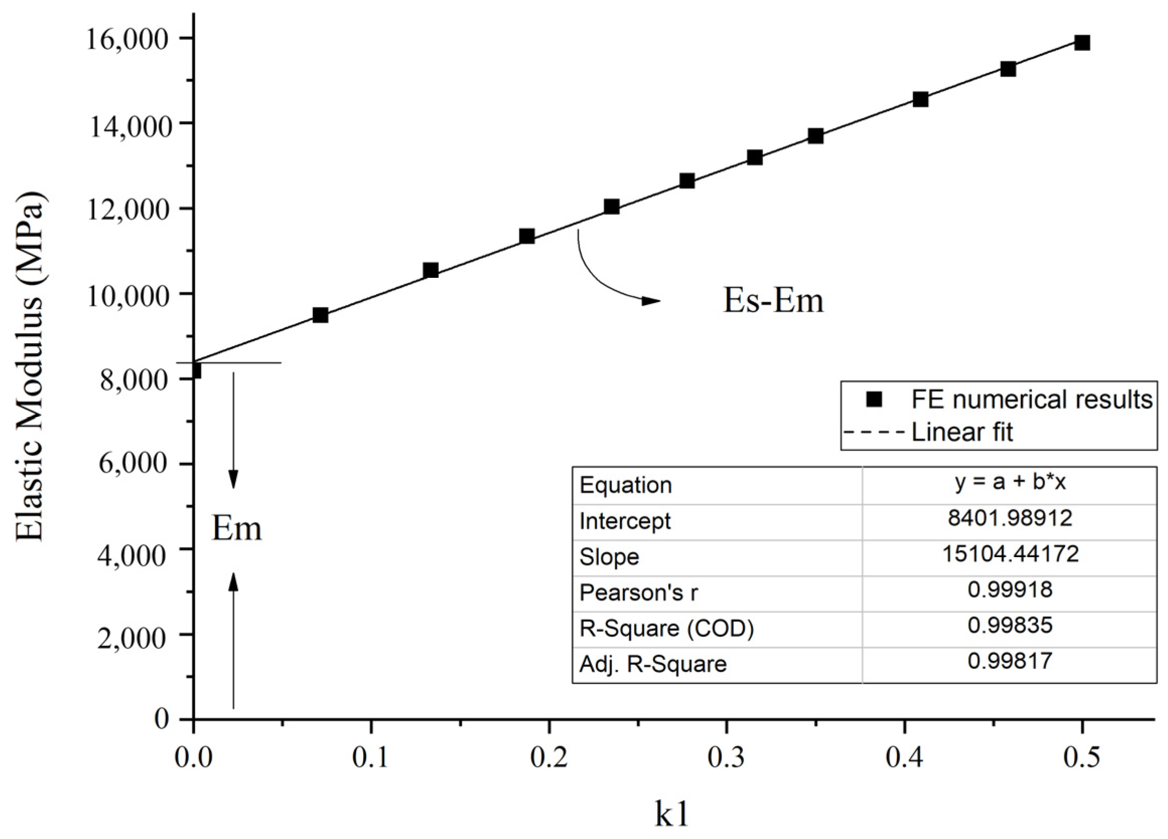
These two relations are a good description of the behavior of the composite wall during the elastic phase. As can be seen in Equation (12), the composite wall versus k 1 function is a linear function that has a slope of E s E m intercept of E m .
According to the methods mentioned above, a linear fit was made to the FE numerical results verses k 1 (ratio between the cross-section of the sprayed layer and the composite wall) the plot, which is shown in Figure 14. The linear fit R-squared is 0.998. The intercept in the fit results is 8401, which corresponds to the modulus of elasticity for the reinforced brick wall E m , which is 8576 in the FE simulation results and the slope is 15,104, which corresponds to E s E m , which is 14,130 in the FE simulation results. It could be said that the fitting results are generally consistent with Equation (12).
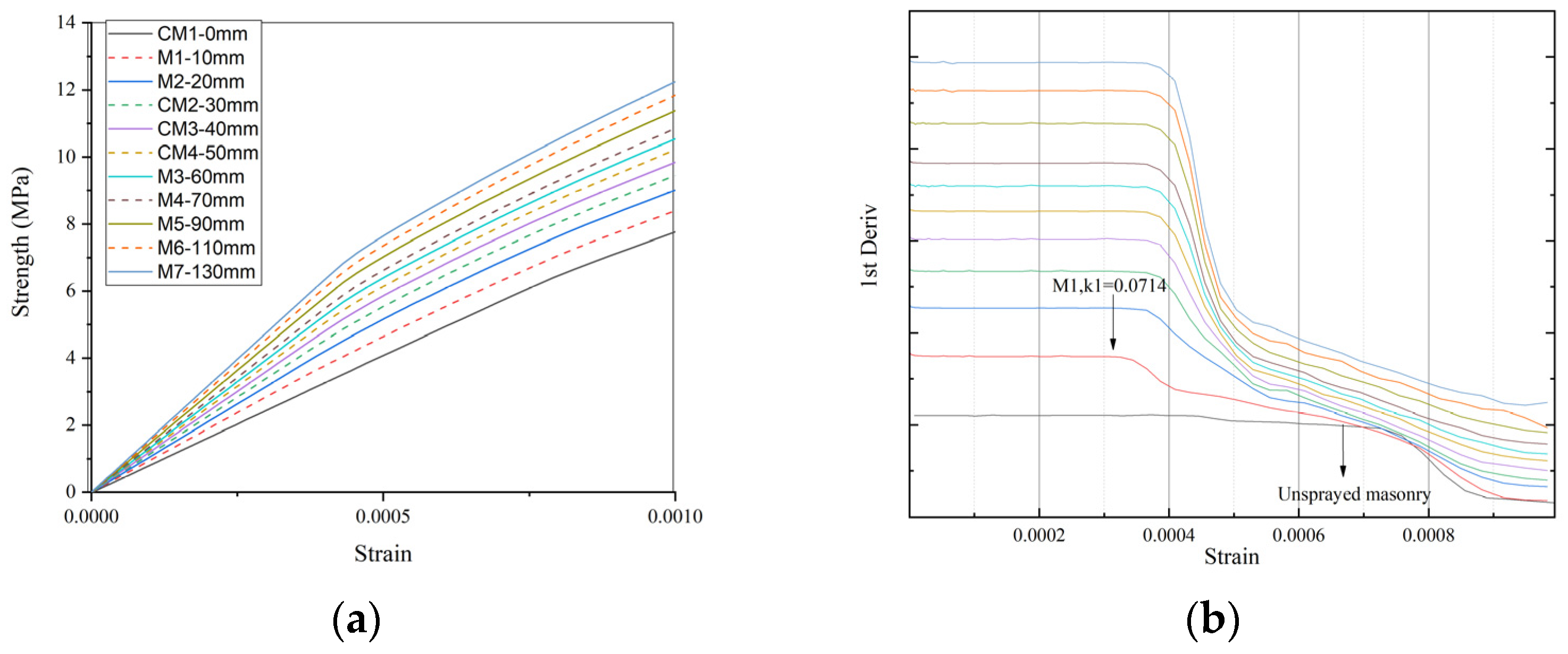
The stress-strain curves of the simulation results in the elastic phase are listed, which are shown in Figure 15. It is found that they do not have the same range of the elastic phase. A differential observation of the change rate for these curves shows that the unsprayed masonry wall has the longest elastic phase, which goes to a strain of about 0.00068. An excessively thin sprayed layer reduces the elastic phase; for example, M1 has only a 10 mm sprayed layer, and it is the smallest of all the results. In addition, when the spraying thickness increases, the elastic phase tends to stabilize.

6.2. Ultimate Strength

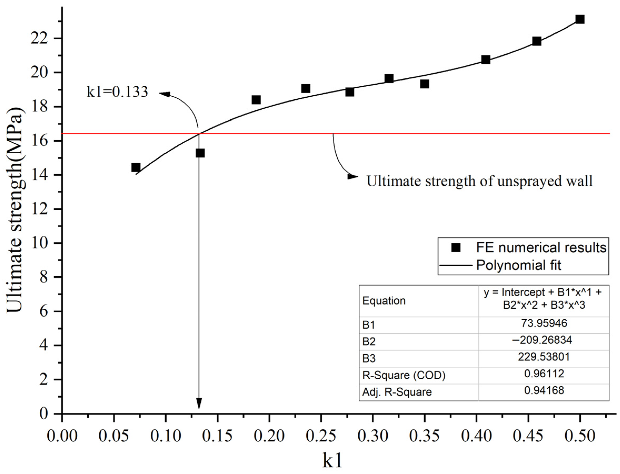
The experimental results of the ultimate strength and the FE results of the ultimate strength were also compared in ultimate strength verses k 1 plots, which are shown in Figure 16.
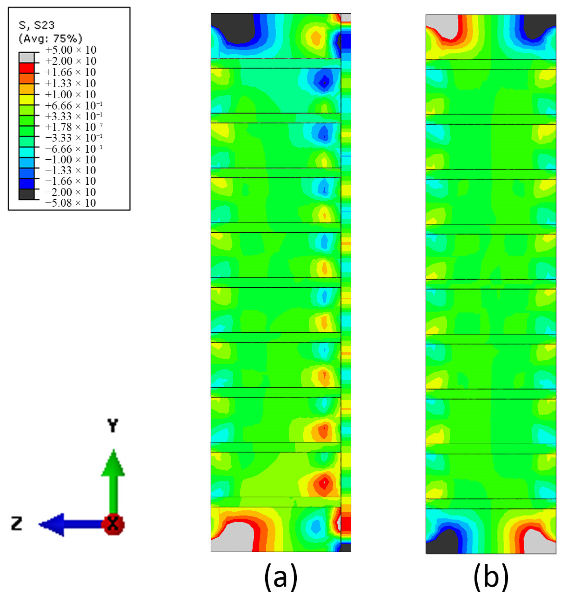
As seen in the diagram, when k 1 is smaller than 0.133, the spray layer reduces the ultimate strength of the composite wall. This phenomenon may occur since the elasticity modulus of the sprayed layer is higher than the modulus of the masonry, it is like a constraint has been formed at the edge of the masonry wall on where the sprayed layer and the brick wall meet. It may make more shear stress on the brick close to interface, which may lead them to earlier damage. This damage probably give a local fracture and finally lead to a instability to the entire structure which happened much earlier than the masonry wall don’t have the sprayed layer. This speculation is also corroborated by the results of the FE analysis. Figure 17 shown the shear stress contour map of M1 and CM1. Can be seen the shear stresses on the brick close to the sprayed interface as shown in Figure 17a appear significantly larger than those at the edges of the brick wall without the sprayed layer as shown in Figure 17b. This phenomenon is alleviated with the increase in the thickness of the sprayed layer.
On the other hand, to clearly study the effect of k 1 on the ultimate strength, the fitted function in Figure 16, shown in Equation (13), is derived to obtain the change rate of strength as shown in Equation (14).
y = 229.54 k 1 3 209.27 k 1 2 + 73.96 k 1 + 9.74
y = 688.62 k 1 2 + 418.54 k 1 + 73.96
The k 1 value corresponding to the minimum value of the Equation (14) function is first found to be 0.303 by using the method of finding the extreme value of the function. Then the k 1   value of 0.133 that distinguishes the strength contribution, as mentioned before, is also drawn in Figure 16. Then it is possible to divide the rate of change in intensity into three intervals, I, II, and III, as shown in Figure 18.
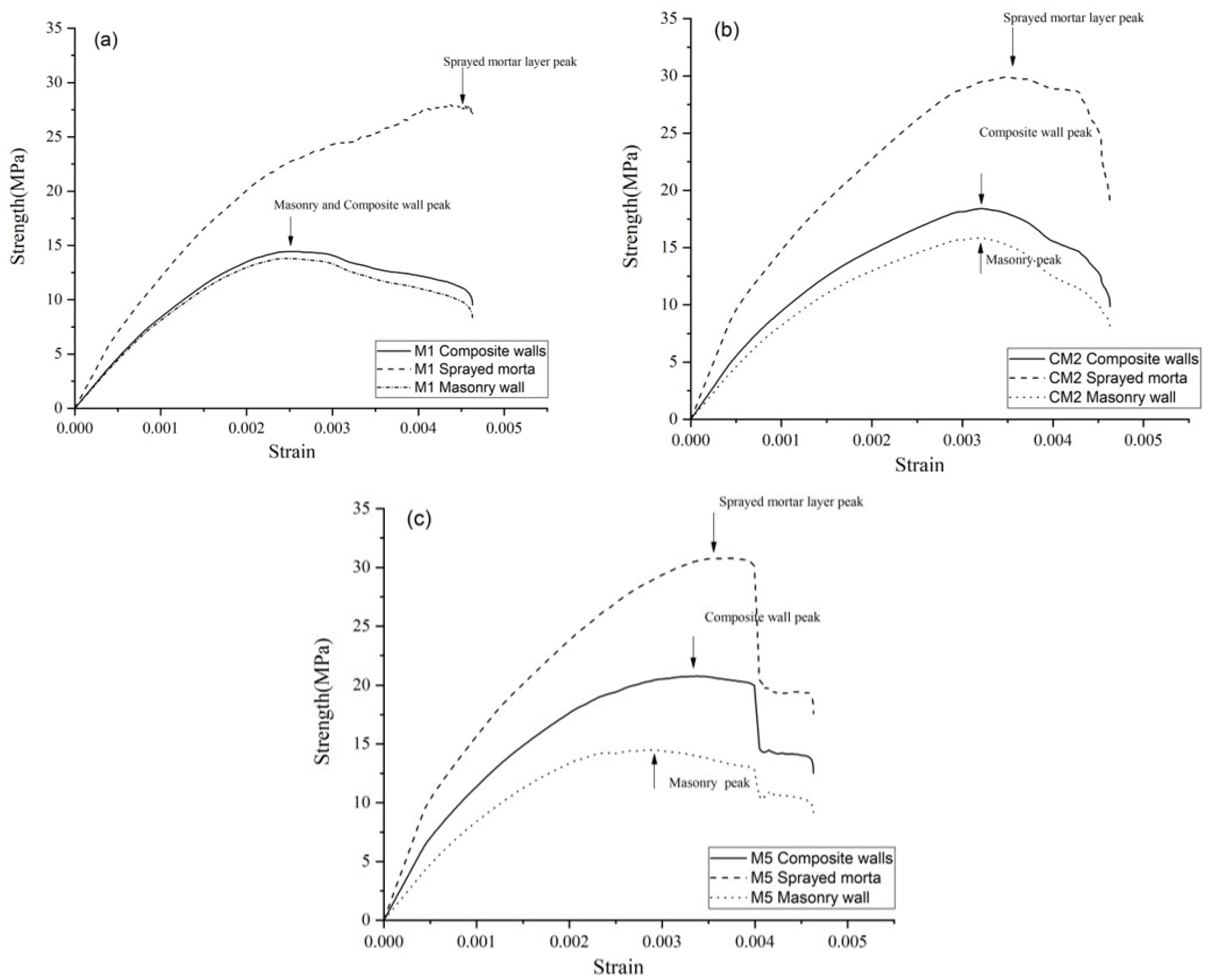
It can be seen in Figure 18 that the contribution of the thickness of the sprayed layer to the ultimate strength in interval I is negative. Interval II shows a decreasing, exponential decrease from the high-efficiency contribution from 0.133 to 0.303, which indicates that the efficiency of the contribution of the spray layer thickness to the ultimate strength tends to level off in this interval. In contrast, interval III shows an increasing exponential increase from 0.303. This indicates that the contribution of the thickness of the sprayed layer to the ultimate strength becomes more and more significant in this interval. To better understand the behavior of these three intervals, the stress-strain behavior curves of the composite wall, masonry wall, and sprayed mortar layer, respectively, were made from the FE numerical analysis results. Figure 19 shows the stress-strain curves.
For this part, three representative FE models were selected. The first one is M1, which has k 1 less than 0.133 because the sprayed layer contributes negatively to the ultimate strength of the wall at this stage. The stress-strain curves are shown in Figure 17a. For the same reason, two more samples were selected for analysis. They are CM2 and M5, and their k 1   is 0.185 and 0.41, respectively. CM2 is used to represent interval II, and M5 is used to represent interval III, which are shown in Figure 19b,c.
As can be seen in Figure.19a, the stress peak of the sprayed mortar of M1 is then very far back, at about strain 0.0045, and the stress peaks of the masonry and composite walls almost overlap, and the strain at which the stress peak of the sprayed mortar appears about 0.0025. The elastic modulus of the masonry wall and the composite wall are very close to each other.
The peak stresses of the CM2 spray mortar occur at approximately 0.0035 strain, and the peak stresses of the masonry and composite walls are close to each other, both appearing close to the peak strain of the spray mortar at approximately 0.0032. The elastic moduli of the masonry and composite walls are also close but significantly larger than those of the M1.
For M5, the peak stress of the spray mortar still appears at approximately strain 0.0035, and the peak stress of the composite wall is also at 0.0032, but the peak stress of the masonry wall regresses to approximately 0.0028. The elastic modulus of the composite wall is between that of the sprayed mortar and the masonry wall.
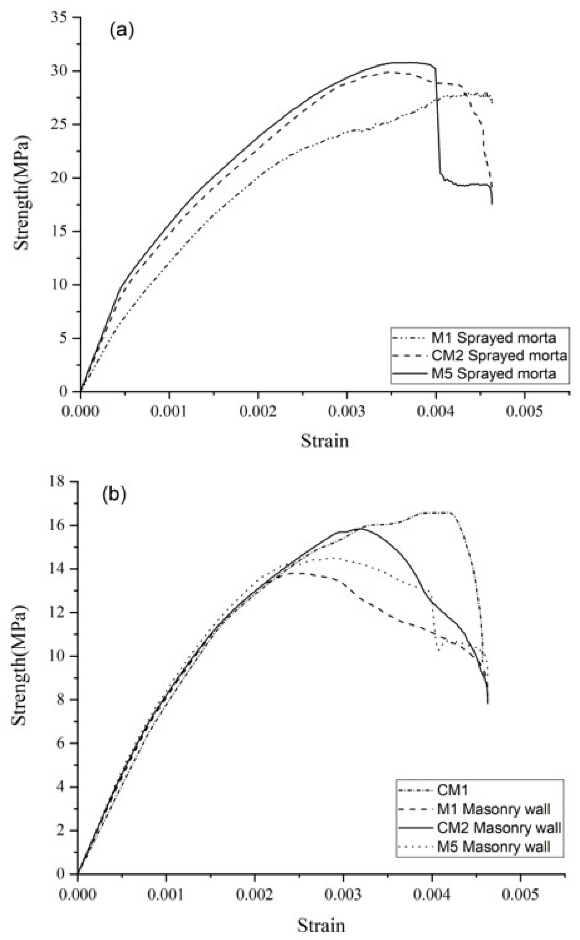
In addition, the authors also compared the stress-strain curves of the spray mortar and masonry walls for M1, CM2, and M5, which are listed in the graphs for comparison. These are shown in Figure 20a,b. The peak stress and elastic modulus of the sprayed mortar layer of M1 are much smaller than those of CM2 and M5, which are positively related to the thickness of the sprayed mortar layer. As for the masonry walls, their elastic moduli are similar and are basically at the same level as the unsprayed masonry walls. However, the peak stress of M1 is the smallest, followed by M5, and the largest is CM2, which shows that once the masonry has a sprayed layer, then the bearing capacity of the masonry wall will be greatly reduced, which may be related to the edge shear stress mentioned before. When the thickness of the sprayed layer is in interval II, the bearing capacity of the masonry wall is still increasing, but once it reaches interval III, the bearing capacity decreases.
To summarize the above analysis, when the k 1 value is less than 0.133, the spraying layer is a negative contribution to the ultimate strength of the structure, probably because the spraying mortar layer causes shear stresses to appear at the edges of the masonry wall that were not present before the sprayed, resulting in a premature local stress state reaching failure conditions. When the k 1 value falls between 0.133 and 0.303, the ultimate strength of the composite wall is improved by the sprayed layer. However, more noteworthy than this is that it improves the residual strength of the composite wall, similar to strain hardening. The efficiency exerted by each material at this stage is optimized. The improvement of the ultimate strength of the composite wall by the sprayed layer remains significant when the k 1 value is greater than 0.303. However, there is a significant decrease in the efficiency exerted by the masonry walls, with the sprayed mortar layer playing a dominant role. In addition, the overall failure of the composite wall shows brittleness, and there is no longer strain hardening.
In addition, it should be noted that the ultimate strength of the double-sided 30 mm is close to that of the single-sided 30 mm. However, it has only half of the ultimate strain and a larger modulus than the former, which may indicate that the symmetrical configuration is beneficial for the stability of the composite. The reason for the whole phenomenon may be the slight asymmetry in the wall form, combined with the small quality difference and the tiny thickness difference of the sprayed mortar on both sides, which causes them not to reach their peak at the same time, which results in the sudden change in the force of the whole composite if the mortar on one side loses its load-bearing capacity, thus losing stability. There is also a possibility that the interface adhesion is insufficient, causing the sprayed mortar layer on one side and the brick wall to separate to form a composite, thus losing the load-bearing capacity. A similar situation was encountered in the study by the Azevedo research group [37].

7. Conclusions

This research paper has conducted an updated study on the uniaxial compressive of masonry walls reinforced with sprayed mortar layers through experiments and FE simulations and draws the following main conclusions.
  • Reinforcing masonry walls with sprayed mortar layers can increase the elastic modulus of composite walls. The reinforcement efficiency is proportional to the thickness of the layer. In this case, double-sided reinforcement is more effective than single-sided reinforcement in improving the elastic modulus.
  • An elastic approach is proposed that fit well the behavior of the masonry wall in the elastic phase. It is also found that an over-thin sprayed layer reduces the range of the elastic phase of the composite wall. This phenomenon tends to stabilize with increasing thickness.
  • Reinforcing the masonry wall with a sprayed mortar layer can increase the ultimate strength of the composite wall. The strengthening efficiency is proportional to the thickness of the layer after the critical sprayed layer thickness is reached; before this thickness, the sprayed layer would have a negative contribution to the ultimate strength. The ratio between the critical sprayed layer thickness and composite wall thickness is about 0.133.
  • Considering economic issues, when the k 1 ratio-which is the sprayed thickness divided by the composite wall thickness-is greater than 0.133, and less than 0.303, the highest efficiency of the sprayed layer is achieved.
  • When the k 1 ratio is greater than 0.133 and less than 0.303, and there is significant residual stress in the composite wall after the peak stress, such as strain hardening. This phenomenon gradually disappears with increasing thickness after the k1 ratio is greater than 0.303.
  • Retrofitting masonry walls with sprayed mortar improves the cracking strain of the walls in the small deformation phase.
  • In the elastic phase, the increase in the thickness of the spray layer linearly increases the elastic modulus of the composite. The slope is E s E m .

Author Contributions

Visualization, D.H., Investigation, D.H., Conceptualization, A.A. and O.P., Methodology, A.A. and O.P., Software, D.H., Writing-original draft, D.H., Writing-review & editing, A.A. and O.P., Validation, A.A. and O.P., Supervision, A.A. and O.P. All authors have read and agreed to the published version of the manuscript.

Funding

This article is part of the Spanish government-funded competitive research project BIA2016-78740-R that aims to make advancements in the rehabilitation of urban heritage through sprayed cement mortars towards solutions that contribute to improving the sustainability and resilience of buildings in our cities.

Data Availability Statement

Data is contained within the article.

Acknowledgments

The authors thank the Laboratory of Technology of Structures and Materials “Lluis Agulló” and the professionals working there. The authors also thank the UPC Cluster TITANI initiative.

Conflicts of Interest

The authors declare no conflict of interest.

References

  1. Cornadó, C. Comportament Mecànic-Estructural dels Edificis Històrics de Murs d’obra de Fàbrica de Maó de l’Eixample de Barcelona. Ph.D. Thesis, Universitat Politècnica de Catalunya, Barcelona, Spain, 2015. [Google Scholar]
  2. Yavartanoo, F.; Kang, T.H.K. Retrofitting of Unreinforced Masonry Structures and Considerations for Heritage-Sensitive Constructions. J. Build. Eng. 2022, 49, 103993. [Google Scholar] [CrossRef]
  3. Austin, S. (Ed.) Sprayed Concrete Technology; CRC Press: Boca Raton, FL, USA, 2002; ISBN 9780429078644. [Google Scholar]
  4. Schlumpf, J.; Jahn, M. Sika Sprayed Concrete Handbook; Sika: Baar, Switzerland, 2011. [Google Scholar]
  5. Malmgren, L.; Nordlund, E.; Rolund, S. Adhesion Strength and Shrinkage of Shotcrete. Tunn. Undergr. Space Technol. 2005, 20, 33–48. [Google Scholar] [CrossRef]
  6. Prudencio, P.R., Jr. Accelerating Admixtures for Shotcrete. Cem. Concr. Compos. 1998, 20, 213–219. [Google Scholar] [CrossRef]
  7. Kahn, L. Shotcrete retrofit for unreinforced brick masonry. In Proceedings of the Eighth World Conference on Earthquake Engineering, San Francisco, CA, USA, 1 January 1984. [Google Scholar]
  8. Beushausen, H. The Influence of Concrete Substrate Preparation on Overlay Bond Strength. Mag. Concr. Res. 2010, 62, 845–852. [Google Scholar] [CrossRef]
  9. Cao, X.Y.; Feng, D.C.; Wang, Z.; Wu, G. Parametric Investigation of the Assembled Bolt-Connected Buckling-Restrained Brace and Performance Evaluation of Its Application into Structural Retrofit. J. Build. Eng. 2022, 48, 103988. [Google Scholar] [CrossRef]
  10. Shabdin, M.; Attari, N.K.A.; Zargaran, M. Experimental Study on Seismic Behavior of Un-Reinforced Masonry (URM) Brick Walls Strengthened with Shotcrete. Bull. Earthq. Eng. 2018, 16, 3931–3956. [Google Scholar] [CrossRef]
  11. Ghezelbash, A.; Beyer, K.; Dolatshahi, K.M.; Yekrangnia, M. Shake Table Test of a Masonry Building Retrofitted with Shotcrete. Eng. Struct. 2020, 219, 110912. [Google Scholar] [CrossRef]
  12. Lin, Y.; Lawley, D.; Wotherspoon, L.; Ingham, J.M. Out-of-Plane Testing of Unreinforced Masonry Walls Strengthened Using ECC Shotcrete. Structures 2016, 7, 33–42. [Google Scholar] [CrossRef]
  13. Keshava, M.; Raghunath, S.R. Experimental Investigations on Axially and Eccentrically Loaded Masonry Walls. J. Inst. Eng. Ser. A 2017, 98, 449–459. [Google Scholar] [CrossRef]
  14. BS EN 1052-1; 1999—Methods of Test for Masonry—Part 1: Determination of Compressive Strength. European Committee for Standardization: Brussels, Belgium, 1999; p. 11.
  15. EN 12390-5; Testing Hardened Concrete –Part 5: Flexural Strength of Test Specimens. European Committee for Standardization (CEN): Brussels, Belgium, 2019.
  16. CEN EN 1015-11; Methods of Test for Mortar for Masonry—Part 11: Determination of Flexural and Compressive Strength of Hardened Mortar. European Committee for Standardization: Brussels, Belgium, 1999; p. 12.
  17. Segura, J.; Pelà, L.; Roca, P. Monotonic and Cyclic Testing of Clay Brick and Lime Mortar Masonry in Compression. Constr. Build. Mater. 2018, 193, 453–466. [Google Scholar] [CrossRef]
  18. Thamboo, J.A.; Dhanasekar, M. Correlation between the Performance of Solid Masonry Prisms and Wallettes under Compression. J. Build. Eng. 2019, 22, 429–438. [Google Scholar] [CrossRef]
  19. Angiolilli, M.; Gregori, A.; Cattari, S. Performance of Fiber Reinforced Mortar Coating for Irregular Stone Masonry: Experimental and Analytical Investigations. Constr. Build. Mater. 2021, 294, 123508. [Google Scholar] [CrossRef]
  20. EN 1996-1-1; Eurocode 6: Design of Masonry Structures—Part 1-1: General Rules for Reinforced and Unreinforced Masonry Structures. European Committee for Standardization (CEN): Brussels, Belgium, 2005.
  21. EN 12390-13; Testing Hardened Concrete—Part 13: Determination of Secant Modulus of Elasticity in Compression. European Committee for Standardization (CEN): Brussels, Belgium, 2019.
  22. EN 12390-3; Testing Hardened Concrete—Part 3: Compressive Strength of Test Specimens. European Committee for Standardization (CEN): Brussels, Belgium, 2019.
  23. Page, A.W. Biaxial compressive strength of brick masonry. Proc. Inst. Civ. Eng. 1981, 71, 893–906. [Google Scholar] [CrossRef]
  24. Thamboo, J.A.; Dhanasekar, M. Behaviour of Thin Layer Mortared Concrete Masonry under Combined Shear and Compression. Aust. J. Struct. Eng. 2016, 17, 39–52. [Google Scholar] [CrossRef] [Green Version]
  25. De Oliveria, F.L.; De Hanai, J.B. Axial Compression Behavior of Concrete Masonry. Revista IBRACON de Estruturas e Materiais. 2008, 1, 158–170. [Google Scholar] [CrossRef] [Green Version]
  26. Systèmes, D. Abaqus v6. 12 Documentation-ABAQUS Analysis User’s Manual; Abaqus: Providence, RI, USA, 2012. [Google Scholar]
  27. Lubliner, J.; Oliver, J.; Oller, S.O.E. A Plastic-Damage Model for Concrete. Int. J. Solids Struct. Ing. Civ. Struct 1989, 25, 299–326. [Google Scholar] [CrossRef]
  28. Wang, X.; Lam, C.C.; Iu, V.P. Characterization of Mechanical Behaviour of Grey Clay Brick Masonry in China. Constr. Build. Mater. 2020, 262, 119964. [Google Scholar] [CrossRef]
  29. Wang, G.; Li, Y.; Zheng, N.; Ingham, J.M. Testing and Modelling the In-Plane Seismic Response of Clay Brick Masonry Walls with Boundary Columns Made of Precast Concrete Interlocking Blocks. Eng. Struct. 2017, 131, 513–529. [Google Scholar] [CrossRef]
  30. Bolhassani, M.; Hamid, A.A.; Lau, A.C.W.; Moon, F. Simplified Micro Modeling of Partially Grouted Masonry Assemblages. Constr. Build. Mater. 2015, 83, 159–173. [Google Scholar] [CrossRef]
  31. Funari, M.F.; Spadea, S.; Lonetti, P.; Fabbrocino, F.; Luciano, R. Visual Programming for Structural Assessment of Out-of-Plane Mechanisms in Historic Masonry Structures. J. Build. Eng. 2020, 31, 101425. [Google Scholar] [CrossRef]
  32. Kaushik, H.B.; Durgesh, C.; Rai, C.; Jain, S.K.; Asce, M. Stress-Strain Characteristics of Clay Brick Masonry under Uniaxial Compression. J. Mater. Civ. Eng. 2007, 19, 728–739. [Google Scholar] [CrossRef]
  33. Hao, H.; Tarasov, B.G. Experimental Study of Dynamic Material Properties of Clay Brick and Mortar at Different Strain Rates. Aust. J. Struct. Eng. Eng. Media 2008, 8, 117–132. [Google Scholar] [CrossRef]
  34. Karapitta, L.; Mouzakis, H.; Carydis, P. Explicit Finite-Element Analysis for the in-Plane Cyclic Behavior of Unreinforced Masonry Structures. Earthq. Eng. Struct. Dyn. 2011, 40, 175–193. [Google Scholar] [CrossRef]
  35. Dhanasekar, M.; Haider, W. Explicit Finite Element Analysis of Lightly Reinforced Masonry Shear Walls. Comput. Struct. 2008, 86, 15–26. [Google Scholar] [CrossRef]
  36. Kaw, A.K. Mechanics of Composite Materials; CRC Press: Boca Raton, FL, USA, 2005; ISBN 9780429125393. [Google Scholar]
  37. Azevedo, A.; Delgado, J.Q.; Guimarães, A.; Silva, F.A.; Oliveira, R. Compression Behaviour of Clay Bricks Prisms, Wallets and Walls—Coating Influence. Rev. Constr. 2019, 18, 123–133. [Google Scholar] [CrossRef]
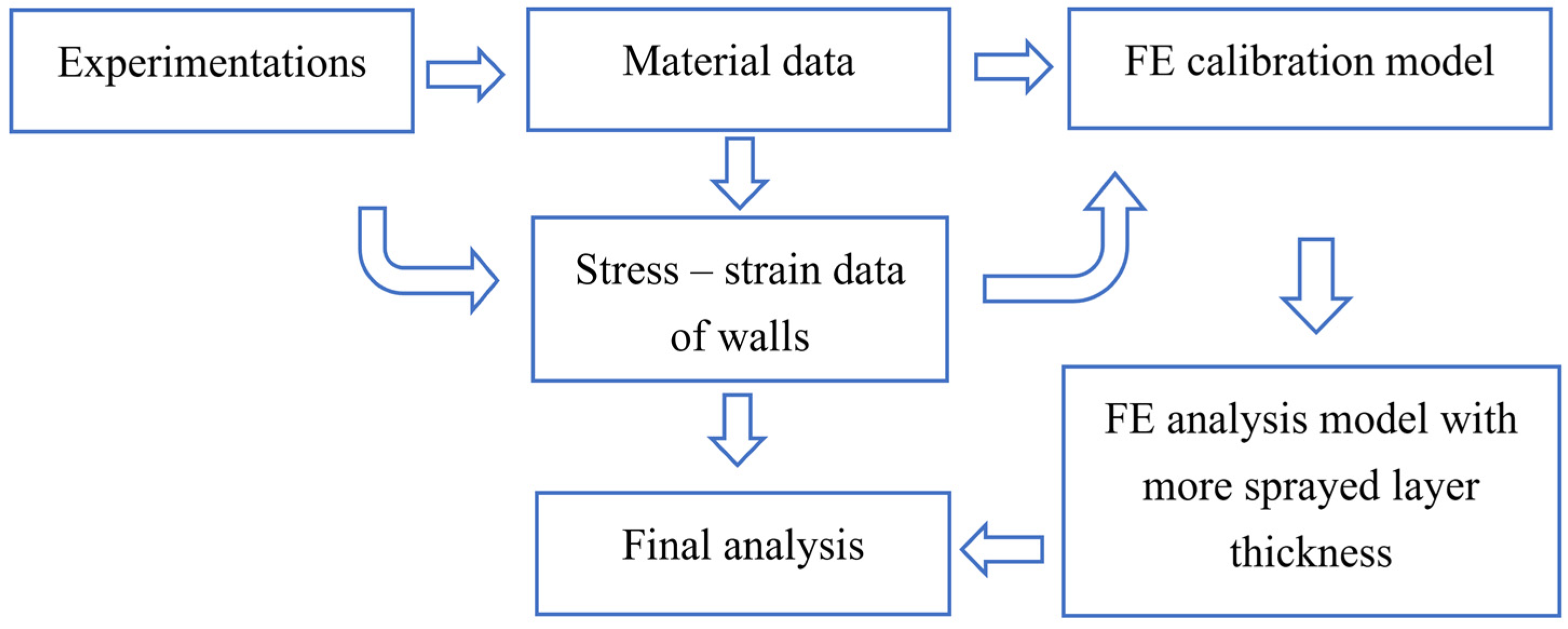
Figure 1. Masonry samples and spraying process.
Buildings 13 00122 g001
Figure 2. Sample preparation process: (a) The construction process of spraying mortar on the wall sample; (b) Finished samples.
Buildings 13 00122 g002
Figure 3. Distribution of the LVDTs, the LVDTs numbered a,b,c,d are used to monitor in-plane displacements, and the LVDTs numbered 1, 2 are used to monitor out-of-plane displacements.
Buildings 13 00122 g003
Figure 4. Photos of mechanical performance tests.
Buildings 13 00122 g004
Figure 5. Modulus test; Compression test.
Buildings 13 00122 g005
Figure 6. Flexural test.
Buildings 13 00122 g006
Figure 7. Force-displacement curves in masonry samples: (a) Sample with single-sided 30 mm thickness of sprayed layer; (b) Sample with single-sided 40 mm thickness of sprayed layer; (c) Sample with single-sided 50 mm thickness of sprayed layer; (d) Sample with double-sided 30 mm thickness of sprayed layer; and (e) Sample without the sprayed layer.
Buildings 13 00122 g007
Figure 8. Stress-strain curves for masonry samples in the load cycle: (a) Comparison of BMWNMA3 and BMWSCA3; (b) Comparison of BMWNMA3 and BMWSCA5.
Buildings 13 00122 g008
Figure 9. Side view of the sample after failure (a) Mode I; (b) Mode II; (c) Mode III.
Buildings 13 00122 g009
Figure 10. Front view of the sample after failure: (a) Mode A; (b) Mode B; (c) Mode C.
Buildings 13 00122 g010
Figure 11. Comparison of the stress-strain curve between the simulated results and the experimental result.
Buildings 13 00122 g011
Figure 12. Damage performance in FE simulation results: (a) damages similar to failure mode II; (b) damages similar to failure mode I; (c) damages similar to failure mode B; and (d) damages similar to failure mode C.
Buildings 13 00122 g012
Figure 13. (a) Stress-strain diagram of the behavior of a compressed composite wall at the same strain; (b) Schematic representation of the behavior of a compressed composite wall under the same strain; E s : Secant modulus of sprayed mortar corresponding to the strain ε m ; E m : Secant modulus of masonry wall corresponding to the strain ε m ; E s m : Secant modulus of composited wall corresponding to the strain ε m ; ε m : Strain at the one-third ultimate strength of the masonry wall.
Buildings 13 00122 g013
Figure 14. Comparison of elastics modulus from experimentation, FE numerical, estimation formula versus k1.
Buildings 13 00122 g014
Figure 15. (a) Stress-strain curves of the simulation results in the elastic phase, and their; (b) Differential curves.
Buildings 13 00122 g015
Figure 16. Comparison of ultimate strength from experimentation, FE numerical versus k1.
Buildings 13 00122 g016
Figure 17. Shear stress contour map from FE result; (a) M1; (b) CM1.
Buildings 13 00122 g017
Figure 18. Function graph of Equation (14).
Buildings 13 00122 g018
Figure 19. Comparison of stress-strain curve from FE numerical; (a) M1, 10 mm sprayed layer sample; (b) CM2,30 mm sprayed layer sample; (c) M5,90 mm sprayed layer sample.
Buildings 13 00122 g019
Figure 20. Comparison of stress-strain curve from FE numerical; (a) Sprayed layer- M1, CM2,M5 (b) Masonry wall-CM1,M1,CM2,M5.
Buildings 13 00122 g020
Table 1. Mixture proportion.
Cement
(kg/m3)
Water
(kg/m3)
Silica Sand
(kg/m3)
Polycarboxylate PlasticizerMultifunctional Additive
Masonry mortar 260 2801540--
Sprayed mortar350 1401650 2.70%1.20%
Table 2. Summary of the five types of masonry samples.
GroupSprayed Concrete ThicknessUnitsCode
1None3BMWNMA1
BMWNMA2
BMWNMA3
230 mm3BMWSCA1
BMWSCA2
BMWSCA3
340 mm3BMWSCA4
BMWSCA5
BMWSCA6
450 mm3BMWSCA7
BMWSCA8
BMWSCA9
530 mm (double face)3BMWSCA10
BMWSCA11
BMWSCA12
Table 3. Property test samples’ main characteristics.
TypeSample TypeTest ContentUnitsCode
1Cylinder of sprayed mortarElastic modulus3smcsma2
smcsma3
smcsma4
2Cuboid of sprayed mortarCompression and Flexural strength3smcusra1
smcusra2
smcusra3
3Cuboid of masonry mortarCompression and Flexural strength3mcusra1
mcusra2
mcusra3
Table 4. Summary of the tests’ procedure.
StageCyclesStepsRate (mm/min)Time (min)Load Related to P0Specimens Estimated Load P0 * (kN)
BMWNMA1-3BMWNMA1-3BMWNMA4-6BMWNMA7-9BMWNMA10-12
131. Lower hold-2≈5%10001600180021002300
2. Loading0.5-5–30%
3. Higher hold-2≈30%
4. Unloading0.5-30–5%
211. Lower hold 4-2≈5%
2. Loading 40.25-5–25%
3. Hold 5-2≈25%
4. Loading 50.25-25–37.5%
5. Hold 6-2≈37.5%
6. Loading 60.25-37.5–50%
7. Hold 7-2≈50%
8. Final loading0.25-50–100%
* Legend: P0 = estimated maximum load.
Table 5. Secant modulus of elasticity of sprayed mortar.
ε p , 2 σ p (MPa) ε a , 3 σ a * (MPa) E s (MPa)
smcsma20.0001080.110.0005178.8121,252.16
smcsma30.0000690.100.0004208.8424,904.54
smcsma40.0000420.130.0004348.8522,258.56
average0.0000730.110.0004578.8322,706.62
* σ a is about 29.3% of the ultimate intensity, which does not reach one-third. The cause was that the loading procedure was calculated based on smcsma1 ultimate strength, which was much lower than the other samples.
Table 6. Summary of strength test results for sprayed mortar and poured mortar.
f c (MPa) Mean
(MPa)
Cov * f c f (MPa) Mean
(MPa)
cov
Sprayed mortarsmcusra137.5636.190.037.767.750.04
smcusra235.467.38
smcusra335.548.11
Masonry mortarmcusra17.287.210.081.991.970.03
mcusra27.911.88
mcusra36.442.04
* Legend: Cov = coefficient of variation.
Table 7. Summary for masonry sample test results.
Group Sample F i , m a x   (kN) Mean (kN)Cov * σ m , u (MPa) Mean (MPa)Cov * E m (MPa) Mean (MPa)cov
1BMWNMA1124711560.0617.1915.940.069190.368688.480.04
BMWNMA2114415.778541.07
BMWNMA3107714.858334
2BMWSCA1136615140.1215.3216.940.1211,774.1711,172.530.11
BMWSCA2177519.9012,273.50
BMWSCA3140215.609469.93
3BMWSCA4195718920.0620.2819.610.0614,165.2913,044.270.06
BMWSCA5197920.4812,237.99
BMWSCA6174118.0712,729.52
4BMWSCA7175819360.1018.1319.470.0911,273.3813,253.630.15
BMWSCA8185518.4312,521.18
BMWSCA9219521.8415,966.32
5BMWSCA10164817660.0915.5416.650.0916,542.1614,870.980.09
BMWSCA11166015.6614,923.02
BMWSCA12198918.7613,147.76
* Legend: Cov: Coefficient of variation; F i , m a x   :Peak load; σ m , u : Peak stress of test; E m : Elastic modulus calculated using the method of EN12390-13.
Table 8. Summary of Failure Modes.
Mode IMode IIMode IIIMode AMode BMode C
BMWSCA1
BMWSCA2
BMWSCA3
BMWSCA4
BMWSCA5
BMWSCA6
BMWSCA7
BMWSCA8
BMWSCA9
BMWSCA10
BMWSCA11
BMWSCA12
Table 9. Summary of the FE model features.
Sprayed Thickness (mm)Content
CM10Calibration Group 1
M110Test
M220Test
CM230Calibration Group 2
CM340Calibration Group 3
CM450Calibration Group 4
M360Test
M470Test
M590Test
M6110Test
M7130Test
Table 10. Summary of material parameters.
Elastic ModulusPoissonDilation AngleEccentricityfb0/fc0 *KViscosity Parameters
Brick32,0000.15300.11.160.670.001
Mortar16500.18
Sprayed mortar22,7060.18
* Legend: fb0/fc0 is the ratio of initial equibiaxial compressive yield stress to initial uniaxial compressive yield stress. K is the ratio of the second stress invariant on the tensile meridian.
Table 11. Summary of CDP parameters.
Masonry mortarYield StressDamage ParameterInelastic Strain
Tensile behavior
200
0.210.70.000403
0.070.90.00364
Compressive behavior
2.500
4.80.20.00133
7.20.350.00511
20.60.0160
Sprayed mortarYield stressDamage parameterInelastic strain
Tensile behavior
7.7500
0.100.90.000354
0.000.990.00102
Compressive behavior
1000
180.050.000502
300.10.00183
36.20.30.00307
210.50.00780
100.80.00911
BrickYield stressDamage parameterInelastic strain
Tensile behavior
3.500
1.050.70.000103
0.350.90.000940
Compressive behavior
800
150.010.000231
220.050.00111
350.150.00390
400.30.00675
110.50.0116
60.80.0248
Table 12. Summary of FE numerical analysis results.
Ultimate Strength (MPa)Elastic Modulus (MPa)
FE numericalExperimentalDif (%)FE NumericalExperimentalDif (%)
CM116.515.9373.53%85768688.481.29%
M114.43- 9491-
M215.28- 10,539-
CM218.416.948.62%11,33911,172.531.49%
CM319.0619.612.80%12,53213,044.273.93%
CM418.8519.463.13%12,94613,253.632.32%
M319.65- 13,196-
M419.33- 13,692-
M520.76- 14,551-
M621.84- 15,268-
M723.11- 15,877-
Disclaimer/Publisher’s Note: The statements, opinions and data contained in all publications are solely those of the individual author(s) and contributor(s) and not of MDPI and/or the editor(s). MDPI and/or the editor(s) disclaim responsibility for any injury to people or property resulting from any ideas, methods, instructions or products referred to in the content.