Abstract
Steel frames equipped with chevron bracing (Λ-CBF) are usually less ductile than other steel systems. Therefore, in many cases, it can be convenient to design Λ-CBF to exploit their stiffness and resistance to enforce a pseudo-elastic seismic response of the building in low to moderate seismic zones. In current EC8, the rules for moderate Λ-CBF are the same as those for high ductile frames, thus potentially leading to massive, over-resistant and uneconomic systems. In the next version of EC8 new rules have been set to design moderate ductile Λ-CBF, aiming to enhance the ease of use of the code as well as to obtain less expensive structures. The new rules of the updated EC8 are based on local requirements and elastic calculation without any plastic analysis. This paper discusses these rules that are numerically investigated by means of nonlinear static analyses on a set of 8-storey steel frames designed for different seismic intensities. The performed analyses show that the frames designed according to the updated EC8 exhibit moderate ductility, preventing damage to brace-intercepted beams and reducing ductility demand on braces under compression.
1. Introduction
Chevron or inverted V concentrically braced frames (Λ-CBFs) are typically characterised by rather high lateral resistance and stiffness but poor ductile response with respect to moment-resisting frames. According to EN1998-1(2005) [1], the seismic design rules for Λ-CBFs are the same for both high and medium ductility classes, thus leading to massive and over-resistant systems, especially in low to moderate seismic zones.
Several Authors [2,3,4,5,6,7,8,9,10,11,12,13,14,15,16,17,18,19,20,21] deepened the seismic design of concentrically braced frames according to Eurocode 8, and they recognised numerous criticisms and difficulties of application of current codified rules, especially in comparison with the rules recommended by North American codes [2,4,7,19,22,23].
The seismic performance of EC8-compliant chevron bracings has been numerically assessed by [3,4,5,6,7,8,11,12,13,14,17,18,19], which showed in which terms the detailing rules of current EC8 lead to massive systems with large lateral overstrength and poor energy dissipation capacity. In particular, the studies by [3,4,12,19] highlighted that the requirement on the variation of overstrength ratio Ω does not avoid either soft-storey mechanism or it assures uniform distribution of damage along the height of the frame. Moreover, it also entails significant difficulties in selecting adequate cross sections, forcing oversized bracings at lower and intermediate levels, thus leading to almost elastic behaviour at a significant damage limit state.
In addition, the studies by [4,5,8,13,17,18,20,21] provided new seismic design criteria devoted to improving the seismic performance of chevron bracings in terms of ductility and energy dissipation capacity for high ductility class, while few European researchers specifically focused on the design of Λ-CBFs for low-to-moderate ductility class. Costanzo et al. [4,5,8] proposed design criteria to overcome the fallacies of EC8 and to improve the seismic performance by controlling the sequence of braces buckling along the building height, while D’Aniello et al. [16] demonstrated that adequate flexural stiffness of the brace-intercepted beams has a key role in guaranteeing the ductile seismic performance of chevron bracings, assuring enhanced engagement of braces under tension, and reduction of damage under compression. Bosco et al. [13] proposed a new design procedure based on an alternative evaluation of the global overstrength factor of the frame. Marino [17,18] proposed a unified approach for the seismic design of high ductility steel frames equipped with concentric bracings, according to which the lateral resistance at each storey is calculated assuming that the tension and compression bracings attain their full yielding and post-buckling strength, respectively. Longo et al. [20] and Giugliano et al. [21] proposed a new design methodology devoted to ensuring the global collapse mechanism.
The upgrading of codified seismic rules for low, medium, and high ductile concentric bracings is a deeply felt topic due to their large employment in seismic areas, by virtue of their simplicity and low cost of construction, as well as their large lateral strength and resistance. However, none of the above-mentioned studies was specifically addressed to investigate the effectiveness of the new seismic design rules for moderate ductile chevron concentrically braced frames compliant with the next Eurocode 8 [24]. In the next version of EC8 (i.e., prEN1998-1-2 [24] that is currently under revision at the time of the present article), the rules and requirements for moderate ductile Λ-CBFs have been substantially modified based on the wide existing studies [2,3,4,5,6,7,8,9,10,11,12,13,14,15,16,17,18,19,20,21].
It is worth mentioning that the concept of ductility classes has been significantly revised within prEN 1998-1-1 (2022) [25] with respect to the current version. According to EN 1998-1 (2005) [1], seismic resistant structures can be designed according to two different design concepts: (a) non-dissipative structures and (b) dissipative systems. Structures designed compliant to the concept (a) belong to ductility class low (DCL): they can be calculated based on elastic global analysis, and structural members are verified according to Eurocode 3 [26] (i.e., non-seismic code); capacity design does not apply, and a behaviour factor equal to 1.5–2 is used. DCL can be used solely for low seismicity areas with PGA lower than 0.1 g. Conversely, systems designed according to concept (b) belong to medium (DCM) or high (DCH) ductility classes depending on the expected plastic engagement, and larger behaviour factors are assigned to frames designed with reference to high ductility with respect to DCM. However, no different design rules correspond to different ductility classes, except for the class of cross sections of dissipative members (solely class 1 is allowed in DCH, while class 1 or 2 can be selected in DCM). The same global mechanism is expected regardless of ductility class, while the level of damage differs depending on the behaviour factor and the relevant design base shear. The designer can choose DCM or DCH regardless of seismic intensity.
Conversely, in prEN 1998 (2022), the ductility class is related to the intensity of the earthquake (expressed in terms of “seismic action index” Sδ, see Figure 1) and to the structural performance to which specific design criteria correspond to. Steel structural systems can be designed according to three different ductility classes: (i) DC1 (low), (ii) DC2 (medium), and (iii) DC3 (high).
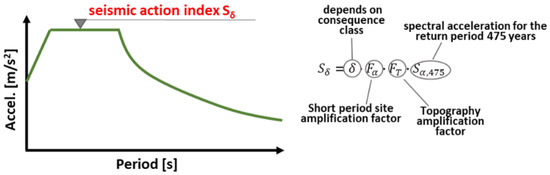
Figure 1.
Seismic action index Sδ according to prEN 1998-1 (2022).
Structures designed according to DC1 exhibit almost elastic behaviour, and the energy dissipation capacity is neglected; design checks of members and connections are carried out according to EC3. General seismic design criteria [24,25] (including the definition of seismic action and criteria of regularity in plan and elevation) apply, while no capacity design rule is considered. Design of CBFs in DC1 is permitted for sites characterised by low/moderate seismicity, i.e., Sδlim,DC1 < 5 m/s2, while for higher seismic intensity, DC2 or DC3 should be selected.
Systems in DC2 are designed according to both local and global simplified design rules devoted to guaranteeing moderate ductility and local deformation capacity adequate to the relevant ductility class: the design requirements in DC2 aim to reduce the local ductility demand rather than to ensure global ductile mechanism occurs. Concentrically braced frames can be designed in DC2 for sites characterised by moderate seismicity, i.e., Sδlim,DC2 < 6.5 m/s2.
For frames designed in DC3 stricter global and local hierarchy and ductility requirements are considered to guarantee global ductile plastic mechanism; the energy dissipation capacity of structural members and/or connections is specifically accounted for; no seismicity limit applies. Larger behaviour factors are provided for the growing ductility class, q = 1.5 for all structural types in DC1 and depending on structural typology in DC2 and DC3.
The main aim of this paper is to investigate the new seismic design rules for low-moderate ductile chevron concentrically braced frames according to the next generation of Eurocode 8 (prEN 1998-1-2(2022)). With this regard, the design rules for chevron concentrically braced frames according to the current and next EC8 are critically discussed and compared. Nonlinear static analyses were performed on 8-storey frames alternatively designed according to current DCM and to DC1 and DC2 to numerically assess and compare the seismic performance of Λ-CBFs compliant to the current and next Eurocode 8, respectively. The paper is organised as follows: Section 2 contains a discussion of the new design rules and requirements. The numerical study and results are presented in Section 3. Conclusive remarks are outlined in Section 4.
2. Evolution of Seismic Design Rules for Moderate Ductile Λ-CBFs
2.1. Behaviour Factors
According to current EN 1998-1, the behaviour factor for a regular structural system is defined as:
where q0 is the reference value of the behaviour factor for regular structural systems, set equal to 2 for chevron bracing in DCM, while αu/α1 is the plastic redistribution parameter accounting for the system overstrength due to redundancy, recommended αu/α1 = 1 for CBFs.
In prEN 1998 (2022), the q factor is given as:
For chevron concentrically braced frames, qS = 1.5, and it accounts for the design overstrength, qR = 1 accounts for the redundancy, and qD accounts for the ductility of the system, and it is set equal to 1.7; thereby, the behaviour factor q is equal to 2.5.
2.2. Design of Dissipative Members
According to the current Code, diagonal members in chevron configuration should be designed to verify at the i-th storey:
where NEd is evaluated by performing global elastic analysis.
The global slenderness (being Ncr,br the Eulerian critical load) of bracing members should be smaller than 2.
To guarantee uniform distribution of damage along the building height and to prevent soft-storey mechanism, the following condition should be met at each storey:
with where and n is the number of storeys.
Local slenderness limits are also provided to limit local buckling phenomena: current EC8 adopts the non-seismic cross-section classification given according to EN 1993, and it limits to class 1 and 2 the choice of the cross-section for diagonal members in DCM.
Design requirements for bracings according to prEN 1998-1-2 do not significantly differ with respect to the current version; the global slenderness requirement is confirmed in the next version, and prEN 1998-1-2 even specifies that the length of the bracings may be taken as the theoretical node-to-node length, disregarding the size of the gusset connections at both brace ends. The buckling length should also account for the degree of restraint given by the brace end connections.
The homogeneity condition expressed by Equation (4) is not considered according to prEN 1998 (2022). Indeed, existing studies [2,3,4,5,6,7,8,9,10,11,12,13] showed such a requirement is not sufficient to prevent soft-storey mechanisms and to ensure uniform distribution of damage along the height of the frame. Moreover, it entails significant efforts in the sizing of bracings members, leading to massive and overstrong systems.
A synoptic comparison of requirements for dissipative members according to the current and next EC8 is provided in Table 1.

Table 1.
Design of dissipative members.
2.3. Design of Non-Dissipative Members
Current EN-1998 (2005) supplies the design rules for non-dissipative members regardless of the ductility class the frame belongs to.
The columns of the braced bays must verify the following inequality:
where:
Npl,Rd(MEd) is the design resistance to the axial force of the beam or column calculated in accordance with EN 1993:1-1 [26], accounting for the interaction with the design value of bending moment;
MEd, in the seismic design situation;
NEd,G is the axial force in the beam or in the column due to the non-seismic actions in the seismic design situation;
NEd,E is the axial force in the beam or the column due to the design seismic action;
γov is the material overstrength factor;
In chevron configuration, the beam is intercepted by diagonal members at mid-length; the design rules aim at preventing plastic hinge forms at braces intersection, conversely entailing significant loss of stiffness and damage concentration at the affected level. Therefore, according to current EC8, the beam should be designed to withstand (i) all non-seismic loads neglecting the intermediate support given by bracings; (ii) the seismic-induced effects evaluated by performing a plastic-mechanism analysis to explicitly account for the force-transfer mechanism, which is activated once the brace under compression buckles. In detail, the diagonal under tension is assumed to transmit its plastic strength () while that under compression attains its residual compression capacity evaluated as , with .
As previously discussed, a simplified design procedure is recommended in the framework of the next prEN 1998-1-2 (2022) for Λ-CBFs in DC2: the resistance and stability of both beams and columns should be verified in compression, bending, and shear considering the most unfavourable combination of the axial force NEd, bending moments MEd and shear force VEd calculated as:
where NEd,G, MEd,G and VEd,G are the axial force, the bending moment, and the shear force in the non-dissipative member due to the non-seismic actions in the seismic design situation and NEd,E, MEd,E and VEd,E are the axial force, the bending moment and shear force in the non-dissipative member due to the design seismic action;
According to Equation (6), the seismic induced effects evaluated by global elastic analysis are magnified by the factor Ω, depending on the dissipative mechanism and fixed equal to 1.5 for concentric bracings.
Different from the current version, prEN1998-1-2 introduces an additional rule to control the beam’s flexural stiffness alongside its strength. Indeed, structures with strong but deformable beams are characterised by poor seismic performance, showing severe damage concentration in the braces under compression, while those in tension behave elastically [2,3,5,6,11,16,27].
In detail, the flexural stiffness kb of the brace-intercepted beams should satisfy the following:
with:
and kbr is the vertical rigidity of the bracing system equal to:
where:
Es is the elastic modulus of steel;
Ib is the second moment of area of the beam section;
Lb is the beam length;
ζ depends on the beam boundary condition (ζ = 4 for fixed ends and ζ = 1 for pinned ends);
Abr is the area of the brace section;
Lbr is the brace length;
α is the angle of the brace with respect to the beam axis.
Synoptic comparison of requirements for non-dissipative members according to current and next EC8 is provided in Table 2.
Table 2.
Design of non-dissipative members.
3. Numerical Study
3.1. Examined Structures
The design procedures given according to current and next Eurocode 8 have been applied to design a set of 8-storey 4 × 4 bays concentrically braced frames, whose plan (a) and elevation (b) configuration is shown in Figure 2, where the location of bracings in both horizontal and vertical directions is shown. The span length is equal to 7 m, while the interstorey height is 4 m at the ground floor and 3.5 at the i-th storey. A rigid diaphragm is s assumed at each level. The structural design for gravity loads and the relevant safety verifications have been carried out according to the non-seismic European codes [26,28,29,30].
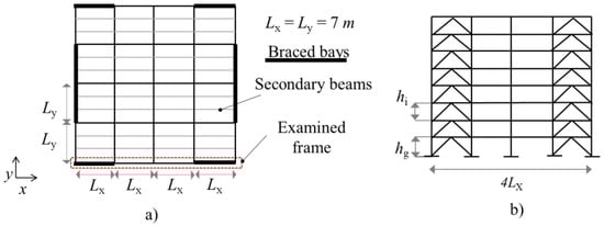
Figure 2.
Configuration of examined frames: (a) plan and (b) elevation.
Permanent and live gravity loads have been assumed to be equal to 5.2 kN/m2 and 2 kN/m2, respectively. Two different seismic intensities have been considered, namely (i) Sδ = 5 m/s2 which corresponds to the threshold value between design in DC1 and DC2 and (ii) Sδ = 6.5 m/s2 which corresponds to the threshold value between design in DC2 and DC3. In addition, a further frame was designed for DC1 for seismic intensity Sδ = 5 m/s2 to compare moderate ductile and non-dissipative design according to prEN 1998-1-2(2022) in terms of seismic performance, as well as design simplicity and material consumption.
The parameters of variation are summarised in Figure 3.
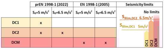
Figure 3.
Parameters of variation of designed structures.
It is worth mentioning the definition of elastic response spectrum according to prEN 1998-1-1 (2022) differs from current Eurocode 8: the amplitude of the constant acceleration branch of the new elastic response spectrum varies as a function of the seismicity class. For the sake of comparison, all designed frames (including those belonging to the current DCM) have been designed by using the response spectrum according to prEN 1998-1-1 (2022).
3.2. Design Results
The geometrical and mechanical properties of structural members for the concentrically braced frames designed for Sδ = 5 m/s2 and Sδ = 6.5 m/s2 are reported in Table 3 and Table 4, respectively. Moreover, to provide easier reading and comparison of design results, the following parameters have been calculated at each level and plotted in Figure 4 and Figure 5 for structures designed for Sδ = 5 m/s2 and Sδ = 6.5 m/s2, respectively:
Table 3.
Geometrical and mechanical properties of structural members of the frames designed for Sδ = 5 m/s2.
Table 4.
Geometrical and mechanical properties of structural members of the frames designed for Sδ = 6.5 m/s2.
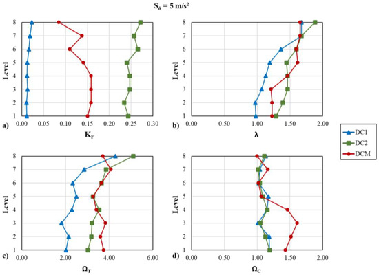
Figure 4.
Design parameters of the frames designed for Sδ = 5 m/s2: (a) beam-to-braces stiffness ratio; (b) brace normalised slenderness; (c) brace overstrength under tension; (d) brace overstrength under compression.
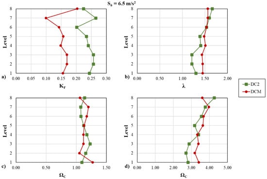
Figure 5.
Design parameters of the frames designed for Sδ = 6.5 m/s2: (a) beam-to-braces stiffness ratio; (b) brace normalised slenderness; (c) brace overstrength under tension; (d) brace overstrength under compression.
- (i)
- (ii)
- (iii)
- (iv)
The largest KF ratios ranging in 0.22–0.24 are recognised for the DC2 frame due to the specific design requirement expressed by Equation (7); Lower values could be recognised for DCM frames, ranging in (0.08–0.16) and (0.1–0.2) for Sδ = 5 m/s2 and Sδ = 6.5 m/s2 respectively; very small KF are calculated for DC1 frame. No significant differences could be recognised for brace normalised slenderness in DC2 and DCM; stockier bracings were selected in DC1 due to the smaller value of the behaviour factor. The brace overstrength ratio under tension is homogeneously distributed along the building height for structures designed according to both DCM and DC2, even though the specific requirement to assure uniform distribution of capacity-to-demand ratio along the building height (see Equation (4)) is solely considered according to DCM (current EC8). The brace overstrength under compression is homogeneously distributed along the building height for structures designed according to DC1 and DC2; larger overstrength could be recognised in DCM structures for diagonals under the fourth storey. Indeed, limiting the variation of the capacity-to-demand ratio of tension braces imposed by Equation (4) forces the designer to oversize the cross-section of diagonals at lower and intermediate storeys.
Figure 6 and Figure 7 depict the material consumption of the designed frames expressed in terms of structural weight (given in tons) (Figure 6a and Figure 7a) and of weight percentage of members (beams/columns/braces) with respect to the total structural weight (Figure 6b and Figure 7b).
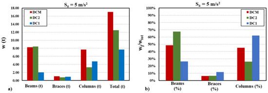
Figure 6.
Material consumption for Sδ = 5 m/s2: (a) structural weight (tons); (b) elements weight as a percentage of total structural weight.
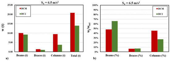
Figure 7.
Material consumption for Sδ = 6.5 m/s2: (a) structural weight (tons); (b) elements weight as a percentage of total structural weight.
The case designed according to current EC8 (DCM) shows the highest material consumption, which is mostly due to the very high value of amplification factor (1.1γovΩ, see Equation (5)). Indeed the capacity-to-demand ratio Ω was evaluated by using the tension-based approach, leading very large value of the amplification factor, even due to the need to satisfy the homogeneity condition of the overstrength variation (less than 25%, see Equation (4)). For frames designed according to prEN 1998 (2022) highest material consumption can be recognised for frames designed with reference to DC2 than DC1, mainly due to the larger beams (see Figure 6b) selected to satisfy strength and stiffness requirements.
3.3. Numerical Assessment of Current and Next EC8 Design Requirements
The non-linear behaviour of examined frames was simulated by using a 2D planar model developed in Seismostruct [31]. Masses are lumped into a selected master joint at each level. A rigid diaphragm was assumed. The vertical loads that are not tributary on the examined 2D frames are assigned to a zero-stiffness leaning column connected to the frames by pinned rigid links to account for second-order effects. The structural members are modelled using the force-based (FB) distributed inelasticity elements, which account for distributed inelasticity through the integration of material response over the cross-section and integration of the section response along the length of the element. The cross-section behaviour is reproduced by means of the fibre approach by assigning a uniaxial stress-strain relationship at each fibre. The steel hysteretic behaviour is simulated by using the Menegotto-Pinto model [32]. The diagonal element’s behaviour is simulated by using the physical-theory model (PTM) according to [33,34]. The bracing members are modelled as fixed in-plane of the frames and pinned out-of-plane. An out-of-plane imperfection Δ0 calculated according to [35] is applied at diagonals at each level. Recent studies [33,34] showed that this approach is the most appropriate to simulate both the buckling and the hysteretic behaviour of bracing elements. Columns are considered continuous through each floor beam, and the beam-to-column connections are assumed pinned. Pushover analyses have been performed considering two different load patterns, namely (i) proportional to the first mode of vibration and (ii) uniform distributions have been alternatively applied.
The accuracy of the adopted modelling assumptions is validated against experimental data, as shown in former studies carried out by the Authors [11,12,13,14,15,16,33,34]
Pushover response curves of examined frames are shown in Figure 8 and Figure 9 for Sδ = 5 m/s2 and for Sδ = 6.5 m/s2, respectively.
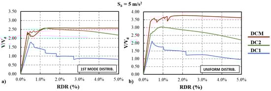
Figure 8.
Pushover response curve of the frames designed for Sδ = 5 m/s2: (a) 1st mode distribution; (b) uniform distribution.
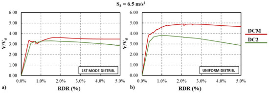
Figure 9.
Pushover response curve of the frames designed for Sδ = 6.5 m/s2: (a) 1st mode distribution; (b) uniform distribution.
The following local response parameters have also been monitored; the maximum value of the two braced bays at each story level is plotted in Figure 10, Figure 11, Figure 12 and Figure 13:
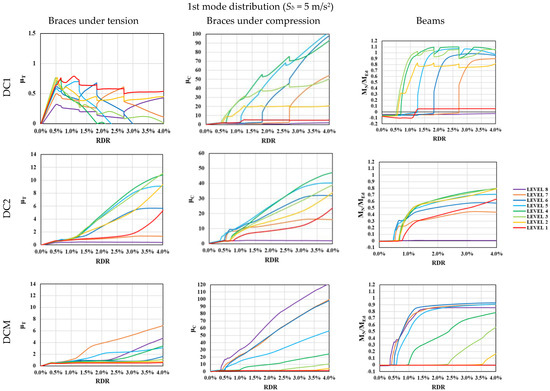
Figure 10.
Local response parameters of the frames designed for Sδ = 5 m/s2 under 1st mode distribution.
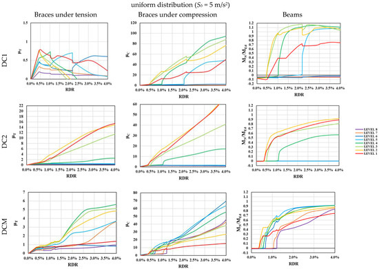
Figure 11.
Local response parameters of the frames designed for Sδ = 5 m/s2 under 1st uniform distribution.
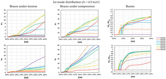
Figure 12.
Local response parameters of the frames designed for Sδ = 6.5 m/s2 under 1st mode distribution.
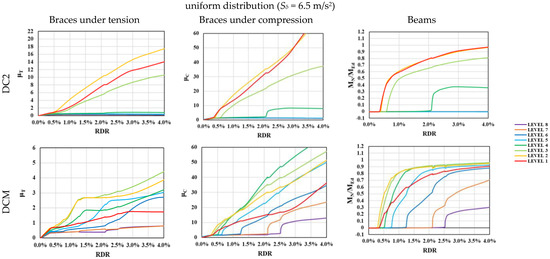
Figure 13.
Local response parameters of the frames designed for Sδ = 6.5 m/s2 under uniform distribution.
- −
- Ductility demand under tension ; dy is the axial deformation corresponding to the yielding
- −
- Ductility demand under compression ; dy is the axial deformation corresponding to the yielding and χ is the buckling reduction factor according to EC3.
- −
- Beam normalised bending capacity ; MN is the bending capacity accounting for the presence of axial force, and MEd is the bending moment acting at the brace-intercepting point.
The DC1 frame exhibits poor seismic performance due to a significant loss of strength and stiffness following the brace buckling (Figure 8). In fact, no plastic engagement of bracings could be observed under tension, while significant deterioration could be recognised under compression; the larger damage concentration is attained at intermediate levels (2–4), where plastic hinges also form in the beams (see Figure 10). The DCM and DC2 frames roughly exhibit similar responses; DC2 frames are more sensitive to second-order effects, being less massive and more deformable with respect to DCM-compliant cases (Figure 8 and Figure 9). Both DC2 and DCM frames exhibit satisfactory response, with most of the diagonals yielded under tension, while brace-intercepted beams behave in the elastic range.
Larger plastic engagement of diagonal under tension combined with lower deterioration under compression is recognised for frames designed according to DC2 (2022) than those compliant with the current DCM. Indeed, yielding under tension () occurs at roof drift ratio (RDR) around 1.0–1.1% at most levels, while diagonals of DCM-frames attain their plastic resistance at RDR > 1.5%, while larger damage under compression could be observed (see Figure 10 and Figure 12)
To allow easier interpretation of both global and local mechanisms, the damage pattern (namely bucked/yielded members) is depicted in Figure 14, Figure 15, Figure 16 and Figure 17 for Sδ = 5 m/s2 and Sδ = 6.5 m/s2, respectively.
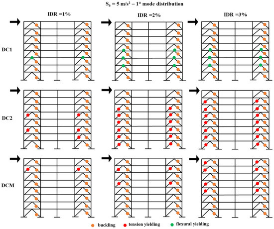
Figure 14.
Buckled/yielded members pattern for Sδ = 5 m/s2 under 1st mode distribution.
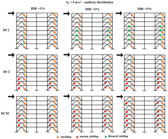
Figure 15.
Buckled/yielded members pattern for Sδ = 5 m/s2 under uniform distribution.
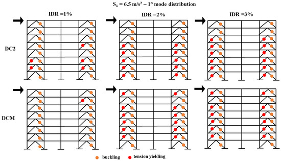
Figure 16.
Buckled/yielded members pattern for Sδ = 6.5 m/s2 1st mode distribution.
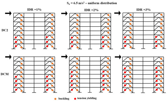
Figure 17.
Buckled/yielded members pattern for Sδ = 6.5 m/s2 under uniform distribution.
It is worth noting that even the simplified DC2 rules give an adequate performance, as well the requirement expressed by Equation (7) plays a key role in preventing damage to brace-intercepted beams and reducing ductility demand on braces under compression.
Results of pushover analyses under uniform loading patterns (See Figure 11 and Figure 13) pointed out that DC2-compliant frames are more prone to develop soft-storey mechanisms than DCM. However, the design rules provided by prEN 1998(2002) for DC2 are not intended to ensure the formation of a global plastic mechanism but solely to reduce the ductility demand where the mechanism forms.
4. Conclusive Remarks
The design procedures of the current and next Eurocode 8 for moderate ductile chevron concentrically braced frames have been investigated. The upgrading of seismic design rules for moderate ductile concentric bracings is a deeply felt topic, due to their large diffusion in seismic areas, by virtue of their simplicity and low cost of construction, as well as their large lateral strength and resistance. The assessment of the new design rules, which will potentially become in force rather soon, represents a key aspect for professionals in the sector as well as for researchers that can contribute to amending such rules before the final approval of the next version of the code.
A set of 8-storey chevron CBFs have been alternatively designed for two seismicity levels according to DCM of current EN 1998-1 (2005) and DC1 And DC2 of prEN 1998 (2022).
Higher material consumption could be recognised for the case designed according to current EC8 (DCM), mostly due to the homogeneity condition of the overstrength variation (less than 25%, see Equation (4)). For frame design, according to prEN 1998 (2022), the highest material consumption is recognised for frames designed with reference to DC2 than DC1, mainly due to the larger beams selected to satisfy strength and stiffness requirements.
Static nonlinear pushover analyses have been performed, and the following remarks can be drawn:
- −
- DC1 frame exhibits poor seismic performance with failure mainly located in the brace-intercepted beams and compression diagonals.
- −
- The frames designed for DCM and DC2 exhibit similar and satisfactory responses, with most of the diagonals yielded under tension, while brace-intercepted beams behave in the elastic range.
- −
- Results show that the simplified DC2 rules assure moderate ductility of the building, preventing damage to brace-intercepted beams and reducing ductility demand on braces under compression. However, DC2 frames are more sensitive to soft-storey mechanisms in case of pushover under a uniform load pattern.
- −
- Further numerical and theoretical investigations are necessary to investigate the local response of the details (e.g., gusset plate connections) and the global response (e.g., assessment of collapse probability, ductility demand, damage distribution, etc.) of moderate ductile chevron concentrically braced frames designed according to the next Eurocode 8. Moreover, a wider range of building archetypes should be analysed.
Author Contributions
Conceptualization, S.C. and M.D.; methodology, S.C.; software, S.C.; validation, S.C. and M.D.; formal analysis, S.C.; investigation S.C.; resources, S.C.; data curation, S.C.; writing—original draft preparation, S.C.; writing—review and editing, S.C., M.D. and R.L.; visualization, S.C.; supervision, R.L. All authors have read and agreed to the published version of the manuscript.
Funding
This research received no external funding.
Data Availability Statement
No further data are available.
Conflicts of Interest
The authors declare no conflict of interest.
References
- EN 1998-1; Design of Structures for Earthquake Resistance—Part 1: General Rules, Seismic Actions and Rules for Buildings. CEN: Brussels, Belgium, 2005.
- Costanzo, S.; Landolfo, R. Concentrically braced frames: European vs. North American Seismic Design provisions. Open J. Civ. Eng. 2017, 11, 453–463. [Google Scholar] [CrossRef][Green Version]
- Costanzo, S.; D’Aniello, M.; Landolfo, R. Seismic design criteria for chevron CBFs: European vs. North American codes (PART-1). J. Construct. Steel Res. 2017, 135, 83–96. [Google Scholar] [CrossRef]
- Costanzo, S.; D’Aniello, M.; Landolfo, R. Seismic design criteria for chevron CBFs: European vs. North American code: Proposals for the next EC8 (PART-2). J. Construct. Steel Res. 2018, 138, 17–37. [Google Scholar] [CrossRef]
- Costanzo, S.; D’Aniello, M.; Landolfo, R. Seismic design rules for ductile Eurocode compliant two storey X concentrically braced frames. Steel Compos. Struct. 2020, 36, 273–291. [Google Scholar] [CrossRef]
- Costanzo, S.; D’Aniello, M.; Landolfo, R. The influence of moment resisting beam-to-column connections on seismic behavior of chevron con-centrically braced frames. Soil Dyn. Earthq. Eng. 2018, 113, 136–147. [Google Scholar] [CrossRef]
- Costanzo, S.; Tartaglia, R.; Di Lorenzo, G.; De Martino, A. Seismic behaviour of EC8-compliant moment resisting and concentrically braced frames. Buildings 2019, 99, 196. [Google Scholar] [CrossRef]
- Costanzo, S.; D’Aniello, M.; Landolfo, R. Proposal of design rules for ductile X-CBFS in the framework of EUROCODE 8. Earthq. Eng. Struct. Dyn. 2019, 48, 124–151. [Google Scholar] [CrossRef]
- Elghazouli, A.Y. Seismic design of steel framed structures to Eurocode 8. Struct. Eng. 2017, 85, 26–31. [Google Scholar]
- Elghazouli, A.Y. Assessment of European seismic design procedures for steel framed structures. Bull. Earthq. Eng. 2010, 8, 65–89. [Google Scholar] [CrossRef]
- Tenchini, A.; D’Aniello, M.; Rebelo, C.; Landolfo, R.; da Silva, L.; Lima, L. High strength steel in chevron concentrically braced frames designed according to Eurocode 8. Eng. Struct. 2016, 124, 167–185. [Google Scholar] [CrossRef]
- Brandonisio, G.; Toreno, M.; Grande, E.; Mele, E.; De Luca, A. Seismic design of concentric braced frames. J. Construct. Steel Res. 2012, 78, 22–37. [Google Scholar] [CrossRef]
- Bosco, M.; Brandonisio, G.; Marino, E.M.; Mele, E.; De Luca, A. Ω* method: An alternative to Eurocode 8 procedure for seismic design of X-CBFs. J. Construct. Steel Res. 2017, 134, 135–147. [Google Scholar] [CrossRef]
- Faggiano, B.; Fiorino, L.; Formisano, A.; Macillo, V.; Castaldo, C.; Mazzolani, F.M. Assessment of the Design Provisions for Steel Concentric X Bracing Frames with Reference to Italian and European Codes. Open Constr. Build. Technol. J. 2014, 8, 208–215. [Google Scholar] [CrossRef][Green Version]
- Campiche, A.; Costanzo, S. Evolution of ec8 seismic design rules for x concentric bracings. Symmetry 2020, 12, 1807. [Google Scholar] [CrossRef]
- D’Aniello, M.; Costanzo, S.; Landolfo, R. The influence of beam stiffness on seismic response of chevron concentric bracings. J. Constr. Steel Res. 2015, 112, 305–324. [Google Scholar]
- Marino, E.M. A unified approach for the design of high ductility steel frames with concentric braces in the framework of Eurocode 8. Earthq. Eng. Struct. Dyn. 2013, 43, 97–118. [Google Scholar] [CrossRef]
- Marino, E.M.; Nakashina, M. Seismic performance and new design procedure for chevron-braced frames. Earthq. Eng. Struct. Dyn. 2006, 35, 433–452. [Google Scholar] [CrossRef]
- Azad, S.K.; Topkaya, C.; Astaneh-Asl, A. Seismic behavior of concentrically braced frames designed to AISC341 and EC8 provisions. J. Construct. Steel Res. 2017, 133, 383–404. [Google Scholar] [CrossRef]
- Longo, A.; Montuori, R.; Piluso, V. Plastic design of seismic resistant V-braced frames. J. Earthq. Eng. 2008, 12, 1246–1266. [Google Scholar]
- Giugliano, M.T.; Longo, A.; Montuori, R.; Piluso, V. Seismic reliability of traditional and innovative concentrically braced frames. Earthq. Eng. Struct. Dyn. 2011, 40, 1455–1474. [Google Scholar] [CrossRef]
- ANSI/AISC Standard 341-16; Seismic Provisions for Structural Steel Buildings. American Institute of Steel Construction, Inc. (AISC): Chicago, IN, USA, 2016.
- CSA-S16-14; Design of Steel Structures. Canadian Standards Association: Toronto, ON, USA, 2014.
- CEN/TC 250/SC 8; prEN 1998-1-2: 2022, Eurocode 8, Design of Structures for Earthquake Resistance, Part 1-2: General Rules and Seismic Action. CEN: Brussels, Belgium, 2022.
- CEN/TC 250/SC 8; prEN 1998-1-1: 2022, Eurocode 8, Design of Structures for Earthquake Resistance, Part 1-1: General Rules and Seismic Action. CEN: Brussels, Belgium, 2022.
- EN 1993:1-1; Eurocode 3: Design of Steel Structures—Part 1-1: General Rules and Rules for Buildings. CEN: Brussels, Belgium, 2005.
- Costanzo, S.; D’Aniello, M.; Landolfo, R.; De Martino, A. Critical discussion on seismic design criteria for cross concentrically braced frames. Ing. Sismica Int. J. Earthq. Eng. 2018, 35, 23–36. [Google Scholar]
- EN 1990; Eurocode 0: Basis of Structural Design. Danish Standards: Charlottenlund, Denmark, 2001.
- EN 1991-1-1; Eurocode 1: Actions on—Part 1-1: General Actions—Densities, Self-Weight, Imposed Loads for Buildings. BSI: London, UK, 2002.
- EN 1994-1-1; Eurocode 4: Design of Composite Steel and Concrete—Part 1.1: General Rules and Rules for Buildings. BSI: London, UK, 2004.
- Seismosoft. SeismoStruct—A Computer Program for Static and Dynamic Nonlinear Analysis of Framed Structures. 2011. Available online: www.seismosoft.com (accessed on 12 October 2022).
- Menegotto, M.; Pinto, P.E. Method of analysis for cyclically loaded R.C. plane frames including changes in geometry and non-elastic behaviour of elements under combined normal force and bending. In Proceedings of the Symposium on the Resistance and Ultimate Deformability of Structures Acted on by Well Defined Repeated Loads, Lisbon, Portugal, 13–14 September 1973. [Google Scholar]
- D’Aniello, M.; La Manna Ambrosino, G.; Portioli, F.; Landolfo, R. The influence of out-of-straightness imperfection in Physical-Theory models of bracing members on seismic performance assessment of concentric braced structures. Struct. Des. Tall Spec. Build. 2015, 24, 176–197. [Google Scholar]
- D’Aniello, M.; La Manna Ambrosino, G.; Portioli, F.; Landolfo, R. Modelling aspects of the seismic response of steel concentric braced frames. Steel Compos. Struct. Int. J. 2013, 15, 539–566. [Google Scholar] [CrossRef]
- Dicleli, M.; Calik, E.E. Physical Theory Hysteretic Model for Steel Braces. J. Struct. Eng. Asce 2008, 134, 1215–1228. [Google Scholar] [CrossRef]
Disclaimer/Publisher’s Note: The statements, opinions and data contained in all publications are solely those of the individual author(s) and contributor(s) and not of MDPI and/or the editor(s). MDPI and/or the editor(s) disclaim responsibility for any injury to people or property resulting from any ideas, methods, instructions or products referred to in the content. |
© 2023 by the authors. Licensee MDPI, Basel, Switzerland. This article is an open access article distributed under the terms and conditions of the Creative Commons Attribution (CC BY) license (https://creativecommons.org/licenses/by/4.0/).