Abstract
GFRP sections with filler concrete material form promising structural components for structures; therefore, the structural performance of them has been investigated with increasing popularity. However, the performance of these composites degrades when fully composite action cannot be developed at the interface in where the literature hosts limited knowledge. Different techniques, such as abraded and sand-bonded surface treatments, were investigated experimentally to improve the bond-slip behavior between GFRP and concrete; however, there is a need to define shear mechanism at the interface of the numerical models. In this study, first, the average frictional bearing strengths were extracted for the treated and untreated inner surfaces using experimental results; then, the coulomb friction model was utilized to transfer the shear stresses between two dissimilar materials. Numerical models were verified by the experimental results, and different parametric studies were investigated by varying the amount and shape of GFRP in the cross section, compressive strength of concrete including the non-linear material behavior and interface frictional contact models. The findings showed that the interface strength can improve the flexural capacity of the concrete-filled GFRP beams by about 15.4%. Square GFRP box sections can be suggested for the construction of hybrid beams instead of rectangular sections, whereas the 10% areal ratio in a square cross section reached 103% load capacity improvement. The increased nominal compressive strength of concrete in hybrid beams can increase the hollow GFRP beams’ nominal load capacities and elastic stiffness of the hybrid beams in between; however, the relative gain is reduced due to increased compressive strength of concrete.
1. Introduction
Engineers have always sought new quests to increase the effectiveness of their design, and composite structures are one of these effective inventions to accommodate in many structures. Reinforcement materials, such as steel and fiber reinforced polymer (FRP), are used to cover concrete’s weakness under tensile stresses [1]. Even though FRP reinforcement does not have plastic behavior and negligible shear strengths in the transverse direction [2], FRPs offer high tensile strength with light material weight along with other promising properties [3,4]. Different forms of FRPs are commonly used in civil industries and are becoming attractive in research activities. Glass FRPs (GFRPs) are generally preferred types of FRPs due to their lower cost and easy access relative to the other counterparts, i.e., carbon and aramid [5,6]. The pultrusion method provides standardized, cheaper, and faster production for hollow structural members [7]. FRP pultrusion method offers new design concepts to the new structures and existing structures by strengthening applications [8]. The use of pultruded GFRP with infilled concrete has been investigated as column members as an alternative to the wrapping with FRP fabrics, and these members are typically subjected to the axial and lateral loads together. Ultimate strength, stiffness, and ductility improvements have been reported for the GFRP columns infilled with concrete columns [9,10,11,12]. Under seismic loading conditions, the use of hybrid FRP columns was suggested [13] due to their extensive lateral deformation capacities. Similarly, the flexural performance of the hybrid beams including fully and partially concrete-filled hollow GFRP sections has been studied by several researchers, [1,14,15,16,17], load capacity and initial stiffness improvements were reported, and partially filled hollow GFRP sections did not cause significant load capacity drops; therefore, optimization of partially concrete-filled GFRP sections was suggested by [9]. Additionally, deflection reductions with hybrid beams allows for utilizing increased span lengths when compared to hollow GFRP beams that have the same cross section [18].
The importance of shear transferring action was addressed in the literature by implementing mechanical shear connectors or adhesively bonded joints between concrete and GFRP sections [19,20,21,22] where the two dissimilar materials contact at one or two faces similar to the single or double lap joints. In a large scale beam, hybrid beam bending tests revealed an obvious slip between the FRP tube and concrete materials [23]. Contact surface strength between the infill concrete and GFRP was studied experimentally within small scale specimens [24,25,26,27]. However, the effect of the confined shear strength of the concrete-filled GFRP beams has not been numerically studied in the literature.
In this study, the structural characteristic of the bond-slip behavior was extracted from the experimental bending tests by selecting the proper friction coefficient for the corresponding surface treatment, and any experimental work throughout the paper refers to the results of [28]. Flexural performance of the hybrid beams due to lack of fully composite action was investigated and the effect of the shear resistance to composite action was articulated in this study. Load capacity and stiffness improvements due to slenderness variation of the hollow GFRP sections and concrete’s compressive strength in a hybrid beam is presented, including the interface shear resistance within the verified numerical models. This study practically guides the designer to quantify material selection for the hybrid beam design and the expected interface fracture stress for specific inner surface treatments.
2. Materials and Methods
2.1. Concrete and GFRP Beams
The validation of the concrete stress-strain behavior was made with the [29] FE program for the nominal compressive strength of 40 MPa concrete cube specimens. In addition to the compressive strength, tension strength of cube specimens was predicted using the same FE model, concrete material behavior for the hybrid beam design was shown in Figure 1a, and an approximate 10.70% error was calculated between the numerical results and adopted experimental [28]. After the FE model validation was confirmed, the nominal compressive strengths of concrete materials were selected from standardized nominal compressive strengths of concrete, and their mechanical properties were obtained from the [30] standard and validated with the FE model results. Table 1 provides the detail of the concrete compressive properties used in parametric studies. The maximum error of 25.6% was obtained from the concrete type that has a 50 MPa compressive strength; however, errors obtained from the tensile strength prediction can be negligible considering the compressive strengths. Nevertheless, it was given here to account for the tensile crack initiation during the FE model analysis. The constructed concrete material model was able to predict tensile and compressive cracking within the pultruded GFRP sections.
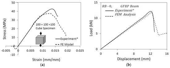
Figure 1.
Verification of numerical material models with adopted experimental result * [28]: (a) Concrete Compression Results; (b) GFRP Beam Bending Results.

Table 1.
Nominal and numerical strength of the concrete.
The lengthwise mechanical properties were adopted from the reference results [28], and the assigned GFRP material properties are given in Table 2 for the considered geometrical GFRP sections. The experimental load-deflection curve of the hollow GFRP beam was validated with numerical analysis as shown in Figure 1b. The difference between load–deflection curves were calculated as load capacity and peak deflection errors and are about 1.12% and 4.21% between the reference work and FE model analysis, respectively. These results are provided in Table 3.
Table 2.
Flexural properties of GFRP material for numerical modelling [28].
Table 3.
Validation of the GFRP beam bending results.
2.2. Finite Element Modelling
Pultruded GFRP box beams were set under a four-point loading test with 1500 mm gross span and 1350 mm clear span length. One typical test set-up representation with different cross-sections and dimensions can be seen in Figure 2a. The square box GFRP sections were tested in flexure where the outer width and height are 100 mm with 4 mm wall thickness. For the rest of the numerical analysis, the properties of the GFRP sections were assumed to be identical to the ones obtained from the experimental results. Typical cross sections of the validated numerical results are given in Figure 2b.
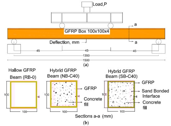
Figure 2.
(a) Four-point test configuration of the GFRP beams; (b) Cross sections with reference, RB-0, natural, NB-C40, and sanded surfaces, SB-C40.
Structural solid brick elements, SOLID185, were selected from [29]’s library, and the material properties of the GFRP materials given in Table 2 were assigned to the FE beam models. The maximum stress failure criterion was defined for the GFRP material in both directions using the critical fracture stresses given in Table 2. When the bottom layer of GFRP reaches the failure criteria, the stiffness of that element is multiplied by the stiffness reduction factor (0.90), due to the elimination of the numerical convergence issues after crack initiations; therefore, the load started to drop when the critical stress criterion was satisfied. An FE mesh study was investigated using three different element sizes, 120 mm, 80 mm and 20 mm, and all three yielded similar numerical results with negligible differences in hollow GFRP beam models; however, the smallest element size, 20 mm, was assigned to the FE models to capture the contact interface sliding accurately for the hybrid beam models [31]. The interface layer was constructed by the contact definition by using the COTA173 and TARGE170 elements to account for the inner surface friction strength due to flexure. The contact algorithm equation at the interface was defined in Equation (1).
The initial study showed that the constructed FE models can accurately predict the reference work using concrete and GFRP material models; therefore, maximum load capacities, fracture initiations, and relative material stiffness including the interface slip behavior between the concrete and GFRP beam were studied with the developed FE models. The later investigations focused on the parametric study of the hybrid beam models where the GFRP beams were filled with concrete material.
The notations can be read as:
- = shear stiffness in contact region,
- = normal stress in contact region,
- = incremental slip in longitudinal and transverse directions in contact region,
- = equivalent slip increment in longitudinal and transverse directions in contact region,
- = the friction stress in longitudinal, , and transverse directions, ,
- = frictional coefficient.
3. Parametric Inputs of the Numerical Studies
The important design aspects of the hybrid beam models are presented in this section. The selected parameters and their values are defined in the numerical models, and detailed explanations are provided in each subsection before presenting the results.
3.1. Inner Surface Bearing Strength
The important aspect of two dissimilar materials working together is the interface slip behavior where the slip starts and how it affects the composite action. This will be addressed in the FE models with the friction coefficients, which allow slip when the interface shear stresses exceed the critical shear stresses at the interface of the concrete and GFRP beam. Natural, NB and sand-bonded, SB, hollow beams were filled with concrete that has a nominal 40 MPa compressive strength of CL40, as obtained from the reference work. In the first part of the numerical study, inner surface bearing strengths were determined by the assigned contact model. A normal hybrid beam, NB-CL40, was investigated where there was not any mechanical surface treatment applied other than roughening and cleaning the inner surface. This was named the natural friction coefficient between the GFRP and concrete materials. In the second surface treatment, the inner surface of the GFRP beam was sand-bonded to create additional mechanical contact between the GFRP and concrete materials [28], and this was considered the sand-bonded hybrid beam with infilled concrete, SB-CL40. It was assumed that surface friction coefficients were independent from the compressive strength of the concrete. Even though this can be a subject of another study, a slight variation may be expected for the slip behavior due to the variation of concrete’s compressive strength.
3.2. Areal GFRP Reinforcement Ratio in Different Cross-Sections
The relative amount of GFRP material in concrete-infilled GFRP hybrid beams was investigated in this part of this study. Three different cross-sections, square, rectangular and tube, are considered to vary the GFRP area in a cross section. The gross area was kept constant while varying the GFRP’s wall thicknesses which corresponds to the 10%, 15%, 25%, 35% and 50% of the cross-sectional area. The slenderness of the hollow square and hollow rectangular (100 × 100 and 100 × 50, height × width dimensions in mm) sections, and tubular section (100 mm outer diameter) in a hybrid beam model were considered by varying GFRP wall thickness. It was assumed that the hybrid beams were modeled with infill concrete that have a 40 MPa compressive strength and sand-bonded surface treatment, which has a 0.3 friction coefficient. The details of the cross-sections and other modelling parameters are presented in Table 4. The performance of these hybrid beams with varied GFRP wall thicknesses was investigated by their nominal and normalized aspects of engineering judgments. Normalized results were obtained by dividing the nominal hybrid beam results by the hollow beam’s, removing the infill concrete from the section while keeping the others constant.
Table 4.
Properties of the cross-sections for areal ratios.
3.3. Filler Concrete
The compressive strength of the infill concrete material in the hybrid beams was investigated by varying the nominal compressive strengths of the infill concrete from 16 MPa to 50 MPa (C16, C20, C30, C40, and C50). The GFRP beam was modeled the same as the reference GFRP beam’s geometry that has a 100 mm × 100 mm cross section, 4 mm wall thickness and a 1350 mm clear span length, and was tested under four-point bending test configuration. The section names and properties of the investigated beams are given in Table 5 with the considered compressive strengths of the infill concrete materials. The interface of the concrete and GFRP section was assumed to have some level of mechanical friction, and it was taken as the same as the experimentally obtained 0.3 friction coefficient of the sand-bonded hybrid beam. Therefore, it was assumed that the surface friction coefficient does not depend on the concrete’s compressive strength but on the surface condition. The flexural performance of the hybrid beams for different types of concrete materials will be discussed in this section.
Table 5.
Compressive strength of different concrete fillers.
4. Results and Discussions
4.1. Characterization of the Inner Bearing Strength
The bond-slip behavior of the hybrid beams was investigated by extracting their maximum friction stresses and sliding distances over time. The intensity of the friction stresses increased as the friction coefficient was increased for the roughened surfaces, and the changes due to friction coefficients are given in Table 6. The upper and lower bound friction coefficients (fully bonded and 0.001) from the FE models were presented within the same table. Three-dimensional schematic views of the contact elements for the NB-CL40 and SB-CL40 beams at their maximum stresses and sliding distances are shown in Figure 3a–d. The friction stresses were concentrated at load applied lines, where the normal pressures are expected to be high, in Figure 3a,b for the NB-CL40 and SB-CL40 beams, respectively. In parallel to the stress concentrations, sliding distances became smaller when the inner surface treatment quality was increased as seen in Figure 3d for SB-C40 beams. The localized stress and sliding contours for the NB-C4L0 beam in Figure 3a,c were more distributed along the contact length when compared to the SB-CL40 beam in Figure 3c,d. Therefore, the provided maximum shear stresses at the interface can be considered 0.07 MPa and 0.24 MPa inner bearing strengths for the concrete-filled GFRP box beams that have natural surface preparations and sand-bonded surface preparations, respectively. The relation between the surface friction coefficients and inner bearing strengths that form the numerical analysis are given in Table 6. On the other hand, there is not any clear definition of the inner bearing strength of the concrete-filled GFRP sections in practice. However, the natural bond strength at the interface of steel and concrete composite members can be predicted using Equation (2) given in AISC 360 (2016) for comparison purposes, and it was predicted to be 0.84 MPa using the same equation and geometrical properties of the GFRP sections, which cannot be larger than 0.7 MPa between the steel and concrete composite sections. Nevertheless, the numerically predicted inner surface bearing strengths given in Table 6 were obtained for less than the code-based calculated value of 0.7 MPa. This concluded that the inner surface bond-slip behavior can be accurately included in the analytical design and numerical modeling approaches for the flexural design of concrete-infilled GFRP beams. Further experimental studies are necessary to calibrate the inner surface strengths due to different surface treatments.
Table 6.
Load and deflections of the GFRP box beam with FE Model Analysis.
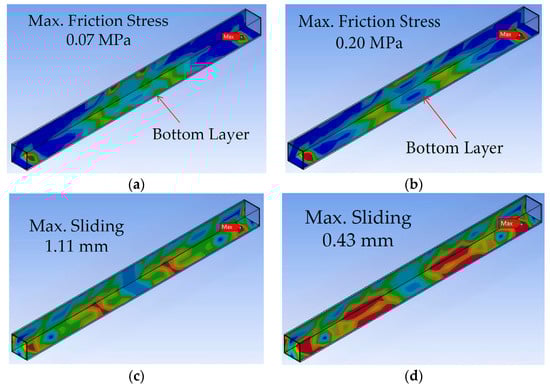
Figure 3.
Maximum stress and sliding distance overtime of the hybrid beams; (a) NB-CL40 Beam; (b) SB-CL40 Beam; (c) NB-CL40 Beam; (d) SB-C4L0 Beam.
The notations in Equation (2) are,
- = Interface bond strength,
- = Wall thickness,
- = Maximum of depth or height in a cross-section.
Frictional coefficients in the FE models were varied from unbonded to fully bonded contact with 0.1 increments, and load-deflection curves of the experimentally studied hybrid beams [28], NB-CL40 and SB-CL40, were compared with the FE model results. It was shown that the peak loads were predicted with a minimal error by choosing 0.1 and 0.3 friction coefficients for normal, NB-CL40, and sand-bonded, SB-CL40, hybrid beams, respectively. The maximum difference between experimental and numerical load capacities was 2.4% and 1.7% among the considered hybrid beams. These results showed that the ultimate load capacities can be approximated with negligible error using numerical analysis. In another numerical study, interface friction coefficients of 0.25 and 0.50 were suggested in axially loaded small-scale columns [27], and two caused negligible differences for the axial load capacities. In the bending of the hybrid beams, the difference can reach up to 19.6% for flexural load capacities. On the other hand, vertical deflections where the ultimate load capacities were captured produced relatively larger errors (7.4% and 29.7%) for the NB-CL40 and SB-CL40 beams using the FE models. Load-deflection curves in Figure 4 showed that the sudden load drop did not develop with the sand-bonded surface treatment. Nevertheless, the peak load capacities were considered as a reference value to validate the FE models and surface friction coefficients. Load-deflection curves from the FE model and experimental results are plotted in Figure 4 with the selected frictional coefficients including the upper and lower bounds. The flexural stiffness of the hybrid beams using the FE models was predicted slightly more than the flexural stiffness of the experimentally tested beams, and gradually increased in parallel to the increased friction coefficients. This behavior can be seen for the sand bonded SB-CL40 hybrid beam in Figure 4; however, stiffness started to drop at about 5 kN when the critical shear stress was reached at the interface. Later, it dropped below the stiffness of the normal bonded beam, NB-CL40, which was normally unexpected and inconsistent with the FE results. Further experimental studies are needed to understand the missing knowledge of the effects of surface treatments for the concrete-infilled hybrid GFRP beams.
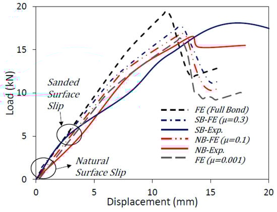
Figure 4.
Load-deflection capacity of hybrid beams with assigned contact friction coefficients (µ).
The maximum reserved load capacity for the fully bonded beam can be calculated to be approximately 15.4% (maximum) more than the load capacity of the naturally bonded beam, NB-CL40. At the same time, deflections can be reduced as much as 9.6% when the reserved load and stiffness capacities of the concrete-filled GFRP beam can be utilized with an improved contact mechanism, as can be seen from Figure 4.
4.2. Areal GFRP Reinforcement Ratio in Different Cross-Sections
The performance of the hybrid beams was presented by the amount of GFRP material in a total cross-section. The areal ratio of the GFRP and concrete was varied by changing the wall thickness of the GFRP beam while keeping the cross-section constant. Areal ratios (10%, 15%, 25%, 35%, and 50%) of GFRP material in a cross-section were represented by the A10, A15, A25, A35 and A50 labels from Figure 5, Figure 6 and Figure 7. For comparison purposes, hollow and hybrid beams’ load-deflection curves were included in these figures. Three different hollow and hybrid beam models with square, SB, rectangular, RB and tubular, TB, cross-sections were investigated, and their results will be compared and discussed in this section. The GFRP beams were compact sections considering the filled steel box and tubular section definitions [32]. These beams are labeled as cross-section—areal-ratio—hollow (O) or hybrid (H) beam order, and SB-A10-O, for example, can be read as a hollow square beam with 10% GFRP in a cross section.
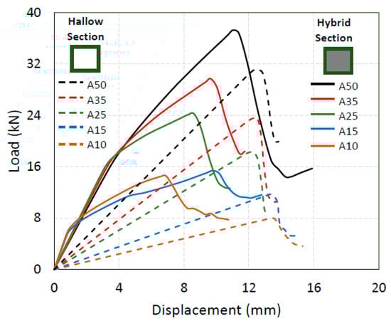
Figure 5.
Load-deflection curves of areal change in square beams.
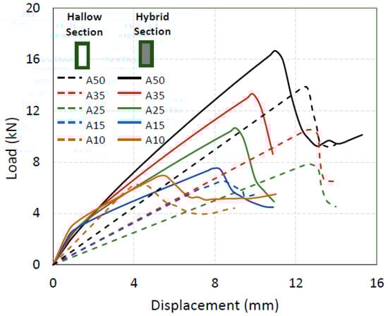
Figure 6.
Load-deflection plot of areal change in rectangular beams.
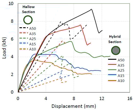
Figure 7.
Load-deflection plot of areal change in tubular beams.
4.2.1. Square Beams, SB
The constant gross area in a square beam was 10,000 mm2 (100 mm × 100 mm) and the wall thicknesses were calculated according to the areal ratios of GFRP from 10% to 50% of the total gross area. Hollow square beams showed linear load-deflection curves until the GFRP reached the rupture stresses, and hybrid beams improved the load capacities, initial stiffnesses and deflections as the amount of GFRP in a section was increased. Typically, hybrid beams showed bi-linear load-deflection curves in Figure 5 following the tension cracks of concrete. When the wall thickness of the GFRP section was increased, the bottom layer of infill concrete moves towards the centroid, and strain at that location becomes smaller; therefore, the tension crack of concrete is postponed, and GFRP can hold the tension stresses until the bottom layer of infill concrete reaches the cracking strain. This concluded the reason for the inflection points on the bi-linear load-deflection curves of the hybrid beams in Figure 5.
The maximum load capacity, 37.8 kN, was attained by the SB-A50-H beam where the maximum areal ratio of the GFRP section was provided; however, the highest load capacity improvement was attained with the SB-A10-H beam by 103% among the hollow square sections. Similarly, the deflections of the hollow beams at their peak loads were reduced between 14% and 50% with the increased GFRP wall thickness. On the other hand, the initial stiffness of the hybrid beams slightly reduced as the wall thickness of the GFRP section increased, as seen in Figure 5. This can be explained by the change of elastic modulus in a cross-section where the increased wall thickness replaces the concrete with GFRP material. Relative elastic modulus between the dissimilar materials in a composite cross-section can yield an initial stiffness increase or decrease depending on the thickness and orientation of the materials in a cross-section. As a result, the hollow square beam with the least wall thickness SB-A10-0 benefited the most from the use of infill concrete among the hybrid beams.
4.2.2. Rectangular Beams, RB
The constant gross area in rectangular beams was 5000 mm2 (100 mm × 50 mm) and the wall thicknesses were calculated using the areal ratios from 10% to 50% of the total gross area. Hollow rectangular beams showed linear load-deflection curves in Figure 6 until the GFRP reaches rupture stresses such as the hollow square GFRP beams. Similar conclusions can be drawn from the square hybrid beam results for the rectangular beams. The maximum load capacity gain was 36% with the hybrid RB-A25-H beam over the hollow RB-A25-O beam, but the rectangular hybrid RB-A15-H and RB-A10-H beams provided the least effective results among the hybrid rectangular beams in terms of the load capacity, deflection, and initial stiffness. Similarly, slender hybrid beam application in a rectangular hollow shape did not produce load capacity gains as effectively as the slender square shapes. Following the tension cracking of the concrete, load-deflections curves of the rectangular hybrid beams showed bilinear behavior. As discussed earlier in the square beam section, the difference between the elastic modulus of concrete and GFRP materials caused the initial stiffness variation for the hybrid beams.
4.2.3. Tubular Beam, TB
Tube GFRP section was another geometrical consideration for the effectiveness of the hybrid beams. The constant gross area in the tubular beams was 7854 mm2 (100 mm diameter) and the wall thicknesses were assigned according to the areal ratios of GFRP from 10% to 50% of the total gross area. Hollow tubular beams showed linear load-deflection curves in Figure 7 until the GFRP reaches rupture stresses such as the hollow square and rectangular beams due to linear material properties. Gradual load capacity increase was obtained with the increased GFRP wall thickness, a maximum relative gain of 84% was obtained by the tubular hybrid TB-A10-H beam, and it was gradually reduced to 21% with the increased GFRP’s areal ratio in the cross-section. One major difference were the deflections at the peak loads for the tubular sections when compared to the hybrid box GFRP sections. The deflections of the hybrid tubular beams before the first inflection point were reduced in descending order as the GFRP thickness was increased, as shown in Figure 7; however, the deflection at the ultimate load capacities was obtained more than their hybrid beam models’ when the tubular section becomes more compact, i.e., TB-A35-H and -TB-A50-H beams.
4.2.4. Comparison of GFRP Section Geometries
The detailed graphical representation of all three cross-sections in a hybrid beam model under flexure is shown in Figure 8 for the normalized load, displacement and stiffness variations by changing the GFRP amount in a total cross-section. The square section is more efficient for the use of load capacity, deflection and stiffness enhancements. When a 25% GFRP ratio in a cross-section was provided in cross section all the sections’ normalized flexural performances became similar except for the deflections of the tubular section. The change of elastic modulus in a cross-section yielded a poor flexural performance for tubular sections. Even though the tubular section had some load capacity and stiffness gain with filler concrete in Figure 7, the tubular sections should not be preferred when the confining GFRP section has a lower modulus than the filler concrete. Additionally, the reduced concrete stress block and reduced moment arm in a tubular shape is expected to yield reduced flexural performances compared to the box shapes. On the other hand, filler material postpones the local buckling of compression flanges for slender tubular sections.
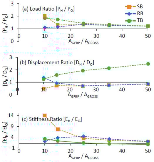
Figure 8.
Effect geometrical shape on (a) loads; (b) deflections; (c) stiffness.
4.3. Compressive Strength of Filler Concrete
The performance of the hybrid beam with different concrete compressive strengths is presented in this section. It should be noted that the tension strength of the concrete was included in these results. Sand-bonded hybrid beam’s experimental results, SB-CL40, were verified by the FE models, and the same FE model was explored with different concrete infill materials given in Table 1. The effect of the concrete compressive strength on the performance of the hybrid square beams is given in Table 7. In this table, the results are presented for the beam’s nominal load capacities, deflections and stiffnesses results. To evaluate the effectiveness of the hybrid beams, load-deflection curves are plotted with their nominal and normalized loads capacities of the hybrid beams in Figure 9.
Table 7.
Different Concrete Strengths Considerations.
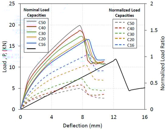
Figure 9.
Nominal and normalized load deflection curves of hybrid beams with varied concrete.
The nominal load capacity of the reference beam, RB-0, was gradually increased from 34% to 60% by increasing the compressive strength of infill concrete in a hybrid beam from 16 MPa to 50 MPa. On the other hand, the economic value of concrete can be measured by its compressive strength; therefore, normalized results were calculated by dividing nominal load capacities by nominal concrete compressive strengths (units in kN per MPa). As opposed to the nominal load capacities, the normalized load capacities showed that the hybrid beam having the lowest compressive strength of concrete as filler, SB-C16, benefitted the most from the hybrid beam model. The economical effectiveness of the hybrid beam gradually reduces with the increased compressive strength of the filler concrete as shown in Figure 9.
The maximum deflection of the SB-C16 beam was obtained at about 8.86 mm which is about 25% less than the reference beam’s, RB-0, deflection. The increased compressive strength of the concrete with SB-C50 beam showed 7.71 mm deflection and this was with about 35% improved deflection capacity of the beam. The difference between the SB-C16 and SB-C30 beam’s deflection was about 1 mm. This showed that the increased compressive strength of the concrete in a hybrid beam has a negligible effect on the deflections. This difference can be inferred as the increase of flexural rigidity of the concrete due to elastic modulus calculation using the compressive strength. These results concluded that the use of hybrid beams provides improved load capacities and filler material selection can be optimized considering the filler’s compressive strength, the of the hybrid beam and the economic value of GFRP beams in a hybrid beam design.
5. Conclusions
Flexural performance of concrete-filled GFRP beams including the inner surface bearing strengths were investigated using the FE models. The experimental results from a reference study were adopted to validate numerical material models, and interface stress distributions were extracted using the FE models. Hybrid beams with the natural and sand bonded surfaces have 0.07 MPa and 0.24 MPa inner bearing strengths, which were found to be represented by 0.1 and 0.3 surface friction coefficients in numerical modelling, respectively. The upper strength limit and surface friction coefficients can be increased with improved further with proper surface contact mechanisms. These results are still immature and require further exploration with more research to be specified in a code provision. The dimensions of the hybrid beams can be reduced with proper interface strengths while improving the flexural stiffness. It was expected that different forms of shear transferring mechanism need to be investigated.
One practical friction coefficient, 0.3, was drawn from the numerical results and included in the parametric results of the hybrid beams. It was found that the hallow square GFRP sections provided the most capacity gain among the rectangular and tubular shapes. The geometry of the tubular section was not found to be suitable for a beam element. The GFRP layer serves as the longitudinal reinforcement for the hybrid beam design; therefore, the amount GFRP has a positive effect on the flexural performance of these hybrid beams. When filler concrete has different compressive strengths in a hybrid beam, the nominal load capacity of the hybrid beams and their initial stiffnesses increased, and deflections at their peak loads were slightly reduced in parallel to the increased compressive strength of concretes. However, when these improvements were judged after normalizing the results per unit concrete strength (per MPa), it was observed that the hybrid beam benefits less with concrete, which has a higher compressive strength. Additionally, GFRP profiles are recommended to be used to protect steel reinforcement against environmental attacks for the hybrid sections when steel is presented in concrete.
Author Contributions
Data curation, A.S.S.; Investigation, T.Ü. and A.S.S.; Methodology, T.Ü.; Validation, T.Ü. and A.S.S.; Writing—original draft, T.Ü. and A.S.S.; Writing—review and editing, T.Ü. All authors have read and agreed to the published version of the manuscript.
Funding
This research received no external funding.
Institutional Review Board Statement
Not applicable.
Informed Consent Statement
Not applicable.
Data Availability Statement
The numerical data is available upon request.
Conflicts of Interest
The authors declare no conflict of interest.
Notations
| Flexural rigidity of GFRP | |
| Interface bond strength between steel and concrete | |
| Maximum of dept or height in a cross-section of steel box | |
| Moment of inertia of GFRP section | |
| Shear stiffness in contact region | |
| Length of specimen | |
| Moment at crack initiation | |
| Moment due to unit load | |
| Normal stress in contact region | |
| Total applied load on four-point bending test | |
| Incremental slip in longitudinal and transverse directions in contact region | |
| Thickness of the specimen | |
| Wall thickness of steel box | |
| Displacement under at the mid-length | |
| Cross head displacement at crack initiation | |
| Frictional coefficient | |
| Critical failure stress at crack initiation | |
| Friction stress in longitudinal, , and transverse directions, |
References
- Fam, A.; Rizkalla, S. Flexural Behavior of Concrete-Filled Fiber-Reinforced Polymer Circular Tubes. J. Compos. Constr. 2002, 6, 123–132. [Google Scholar] [CrossRef]
- Masuelli, M.A. Introduction of Fibre-Reinforced Polymers Polymers and Composites: Concepts, Properties and Processes; IntechOpen: London, UK, 2013. [Google Scholar]
- Bilotta, A.; Ceroni, F.; Nigro, E.; Pecce, M. Strain Assessment for the Design of NSM FRP Systems for the Strengthening of RC Members. Constr. Build. Mater. 2014, 69, 143–158. [Google Scholar] [CrossRef]
- Chan, C.W.; Zhang, S.S.; Yu, T. Circular Fibre-Reinforced Polymer (FRP)-Concrete-Steel Hybrid Multitube Concrete Columns: Compressive Behaviour. Constr. Build. Mater. 2021, 272, 121609. [Google Scholar] [CrossRef]
- Cheung, M.M.S.; Tsang, T.K.C. Behaviour of Concrete Beams Reinforced with Hybrid FRP Composite Rebar. Adv. Struct. Eng. 2010, 13, 81–93. [Google Scholar] [CrossRef]
- Ulger, T.; Okeil, A.M. Strengthening by Stiffening: Fiber-Reinforced Plastic Configuration Effects on Behavior of Shear-Deficient Steel Beams. J. Compos. Constr. 2017, 21, 04017011. [Google Scholar] [CrossRef]
- Abbass, A.A.; Abid, S.R.; Arna’ot, F.H.; Al-Ameri, R.A.; Özakça, M. Flexural Response of Hollow High Strength Concrete Beams Considering Different Size Reductions. Structures 2020, 23, 69–86. [Google Scholar] [CrossRef]
- Al-saadi, A.U.; Aravinthan, T.; Lokuge, W. Structural Applications of Fibre Reinforced Polymer (FRP) Composite Tubes: A Review of Columns Members. Compos. Struct. 2018, 204, 513–524. [Google Scholar] [CrossRef]
- Togay, O. Concrete-Filled FRP Tubes: Manufacture and Testing of New Forms Designed for Improved Performance. J. Compos. Constr. 2013, 17, 280–291. [Google Scholar] [CrossRef]
- Mohamed, H.M.; Masmoudi, R. Axial Load Capacity of Concrete-Filled FRP Tube Columns: Experimental versus Theoretical Predictions. J. Compos. Constr. 2010, 14, 231–243. [Google Scholar] [CrossRef]
- Liao, W.-C.; Perceka, W.; Tseng, L.-W.; Nguyen, D.-T. Cyclic Behavior of High-Strength Fiber-Reinforced Concrete Columns under High Axial Loading Level. ACI Struct. J. 2021, 118, 103–116. [Google Scholar]
- Jalalpour, M.; Alkhrdaji, T. Backbone Curves of FRP Confined Concrete Columns for Nonlinear Analysis BT. In 10th International Conference on FRP Composites in Civil Engineering; Ilki, A., Ispir, M., Inci, P., Eds.; Springer International Publishing: Cham, Switzerland, 2022; pp. 1254–1265. [Google Scholar]
- Zhu, C.Y.; Zhao, Y.H.; Sun, L. Seismic Performance of FRP-Reinforced Concrete-Filled Thin-Walled Steel Tube Considering Local Buckling. J. Reinf. Plast. Compos. 2018, 37, 592–608. [Google Scholar] [CrossRef]
- Nordin, H.; Täljsten, B. Testing of Hybrid FRP Composite Beams in Bending. Compos. Part B Eng. 2004, 35, 27–33. [Google Scholar] [CrossRef]
- Muttashar, M.; Manalo, A.; Karunasena, W.; Lokuge, W. Influence of Infill Concrete Strength on the Flexural Behaviour of Pultruded GFRP Square Beams. Compos. Struct. 2016, 145, 58–67. [Google Scholar] [CrossRef]
- Yang, Y.; Xue, Y.; Zhang, T.; Tian, J. Strctural Performance of GFRP Concrete Composite Beams. Struct. Eng. Mech. 2018, 68, 485–495. [Google Scholar] [CrossRef]
- Yuan, J.-S.; Xin, Z.; Gao, D.; Zhu, H.; Chen, G.; Hadi, M.N.S.; Zeng, J.-J. Behavior of Hollow Concrete-Filled Rectangular GFRP Tube Beams under Bending. Compos. Struct. 2022, 286, 115348. [Google Scholar] [CrossRef]
- Liu, T.; Feng, P.; Lu, X.; Yang, J.-Q.; Wu, Y. Flexural Behavior of Novel Hybrid Multicell GFRP-Concrete Beam. Compos. Struct. 2020, 250, 112606. [Google Scholar] [CrossRef]
- Correia, J.R.; Branco, F.A.; Ferreira, J.G. Flexural Behaviour of Multi-Span GFRP-Concrete Hybrid Beams. Eng. Struct. 2009, 31, 1369–1381. [Google Scholar] [CrossRef]
- Manalo, A.C.; Aravinthan, T.; Mutsuyoshi, H.; Matsui, T. Composite Behaviour of a Hybrid FRP Bridge Girder and Concrete Deck. Adv. Struct. Eng. 2012, 15, 589–600. [Google Scholar] [CrossRef]
- Koaik, A.; Bel, S.; Jurkiewiez, B. Experimental Tests and Analytical Model of Concrete-GFRP Hybrid Beams under Flexure. Compos. Struct. 2017, 180, 192–210. [Google Scholar] [CrossRef]
- Alachek, I.; Reboul, N.; Jurkiewiez, B. Experimental and Finite Element Analysis of Push-out Shear Test for Adhesive Joints between Pultruded GFRP and Concrete. Int. J. Adhes. Adhes. 2020, 98, 102552. [Google Scholar] [CrossRef]
- Xie, F.; Chen, J.; Dong, X.; Feng, B. Flexural Behavior of GFRP Tubes Filled with Magnetically Driven Concrete. Materials 2018, 11, 92. [Google Scholar] [CrossRef] [PubMed] [Green Version]
- Gautam, B.P.; Matsumoto, T. Shear Deformation and Interface Behaviour of Concrete-Filled CFRP Box Beams. Compos. Struct. 2009, 89, 20–27. [Google Scholar] [CrossRef]
- Luck, J.D.; Bazli, M.; Rajabipour, A. Bond between Fibre-Reinforced Polymer Tubes and Sea Water Sea Sand Concrete: Mechanisms and Effective Parameters: Critical Overview and Discussion. Fibers 2022, 10, 8. [Google Scholar] [CrossRef]
- Ülger, T. Experimental Investigation of Inner Bearing Strength of the Concrete Filled GFRP Box Sections with Different Contact Mechanisms. Exp. Tech. 2022, 1–12. [Google Scholar] [CrossRef]
- Veerapandian, V.; Pandulu, G.; Jayaseelan, R.; Sathish Kumar, V.; Murali, G.; Vatin, N.I. Numerical Modelling of Geopolymer Concrete In-Filled Fibre-Reinforced Polymer Composite Columns Subjected to Axial Compression Loading. Materials 2022, 15, 3390. [Google Scholar] [CrossRef]
- Aydın, F.; Sarıbıyık, M. Investigation of Flexural Behaviors of Hybrid Beams Formed with GFRP Box Section and Concrete. Constr. Build. Mater. 2013, 41, 563–569. [Google Scholar] [CrossRef]
- ANSYS® Academic Research Mechanical, Release 15, Help System, Material Reference, ANSYS Inc. Available online: https://www.ansys.com/academic/terms-and-conditions (accessed on 1 August 2022).
- Building Code Requirements for Structural Concrete; ACI Committee 318; ACI Committee: Farmington Hills, MI, USA, 2019.
- Ulger, T.; Okeil, A.M. Analysis of Thin-Walled Steel Beams Retrofitted by Bonding GFRP Stiffeners: Numerical Model and Investigation of Design Parameters. Eng. Struct. 2017, 153, 166–179. [Google Scholar] [CrossRef]
- Specification for Structural Steel Buildings; AISC 360; American Institute of Steel Construction: Chicago, IL, USA, 2016.
Publisher’s Note: MDPI stays neutral with regard to jurisdictional claims in published maps and institutional affiliations. |
© 2022 by the authors. Licensee MDPI, Basel, Switzerland. This article is an open access article distributed under the terms and conditions of the Creative Commons Attribution (CC BY) license (https://creativecommons.org/licenses/by/4.0/).