Abstract
Contemporary engineering in the construction field has put forward higher requirements on the value utilization of building information models, and as the prefabricated building is the core of construction industrialization, using BIM (Building Information Model) technology to realize the forward design of prefabricated buildings and maximize the value of BIM is in urgent demand in the current construction industry. However, in the application process of forward design, there is a lack of standardized implementation guidance and mature technical support, leading to many problems such as a redundancy of model information, heterogeneity of data information, and low efficiency of transmission. Based on this, this paper proposes a model view delivery method of forward design for prefabricated buildings. Firstly, a simplified assembly model and an assembly knowledge model are designed and extended with IFC (Industry Foundation Classes), then we realize the knowledge visualization expression by combining with an ontology semantic system. For the model view of a prefabricated building domain, this paper realizes the reusable concept module by ontology IDM (Information Delivery Manual) and properties selection of knowledge graphs, and then completes the model view delivery through data mapping and IfcDoc (Ifc Documentation Generator) tool output. Finally, the implementation model of information delivery management for forward design is built with model view delivery as the central link.
1. Introduction
In recent years, the construction field has paid more attention to the application of building information model (BIM) technology. Forward design means that the design of the project from the conception to the construction and operation and maintenance stages is completed based on a BIM model. In the whole life cycle of the project, there is no need to use two-dimensional drawings to carry out information exchange and data transmission in the traditionnal sense so as to realize the vision of information parameterization, collaborative optimization, and automatic drawing. Whole-specialty and whole-process forward design is a design mode that follows the construction logic, which can give full play to the advantages of BIM parameterization and realize the real value of BIM technology [1].
Meanwhile, with the reduction in the demographic dividend and the sharp increase in labor costs caused by the sharp drop in labor, the State Council has issued policies to vigorously develop the prefabricated construction industry. In view of the factory standardized production characteristics of prefabricated building components, applying BIM forward design to prefabricated buildings, giving full play to the building standardization and digitalization capabilities of BIM technology [2], improving the efficiency and quality of information sharing and collaborative management, is the cornerstone for the realization of the information integration of engineering projects. However, due to the lack of standardized implementation guidance and related technical support, there are still many challenges in the application of BIM forward design in actual prefabricated engineering [3].
In terms of technology support, there is a need for not only applicable software, but also accurate data sharing and collaboration [4]. At present, the mainstream BIM software in the construction market includes:
- (1)
- Autodesk’s revit series software;
- (2)
- Graphisoft’s ArchiCAD series software;
- (3)
- Bentley’s Bentley series software.
The mainstream BIM software can achieve smooth data exchange on their respective BIM system platforms; the function of the application is relatively mature. However, it is difficult to realize the BIM forward design of all specialties in a project using only the software products of one manufacturer. At this time, the importance of BIM data standards is reflected [4]. To meet the application demands, not only technical data standards but also application standards are needed. The US proposed the NBIMS standard in 2006 [5] and has been actively promoting a 3D design modeling standard to replace the 2D standard in the past few years. The UK has also made detailed requirements for BIM applications in a strategic document in 2011 [6]. In addition, many scholars have developed interfaces between software to achieve the data transfer of BIM information between different software platforms. In the Chinese construction market, China still adopts the mapping standard of 2D design, which has the weaknesses of repeated application and low efficiency. The design, labeling, and drawing standards of foreign BIM software do not match with domestic drafting standards.
Figure 1 combs the challenges and solutions of the BIM software application of forward design [1,7]. First, Figure 1 shows the forward and collaborative design mechanisms of BIM technology in the design stage, and further demonstrates the forward design software involved in structural specialty and illustrates the interaction between the software. Then, it illustrates the challenges faced by the application of BIM technology for forward design in the design stage and the corresponding solutions. As shown, industry foundation classes (IFC), the international framework for dictionaries (IFD) and the information delivery manual (IDM) are the three types of standards for software development in the construction industry [8]. Data exchange based on open common standards is more suitable for collaborative applications of BIM technology, but the lack of model views in specific exchange scenarios restricts the development of specialty software. Therefore, this paper takes model view delivery in forward design as an entry point for research.
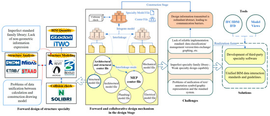
Figure 1.
The status of BIM software application of forward design.
There are still some challenges in realizing the model view delivery of BIM forward design:
- The guidance standard for the implementation is not well developed.
- Model information is redundant and incomplete. The inconsistency of data standards of each participant leads to the duplication of model information.
- Data information is heterogeneous and at a low utilization rate.
Due to the data heterogeneity, there is a lack of unified semantic description and machine identification. In another specific scenario, the reuse of data cannot be realized on the basis of the existing MVD (model view definition), it still needs to be redefined, so the information utilization rate is low.
Therefore, this research proposes a method of model view delivery of forward design for prefabricated buildings, which provides new ideas to solve the above problems; the method firstly designs a simplified assembly model and carries out information extraction and collaborative design among the specialties based on the extended IFC architecture, systematically solving the key problems of the standardization, intelligence, and integration of prefabricated buildings. Meanwhile, the integrated delivery of data information based on IDM and MVD is used as a grip to realize BIM forward design. This paper constructs an assembly knowledge model, and establishes an extensible ontology model through data mapping transformation combined with the ontology semantic system, which solves the problems of data heterogeneity and inadequate semantic expression for the integrated delivery based on IDM and MVD, realizes the reuse of information, and improves the efficiency of data utilization; it truly promotes the collaborative work of multi-stakeholders.
2. Literature Review
2.1. Assembly Modeling
The concept of “assembly” begins with the assembly of parts and components in the mechanical design industry. It refers to the process of assembling the parts according to the specified technical requirements and becoming qualified products after adjustment and testing. The construction industry has always adopted the concept of assembly in the process of development [9], splitting the whole building, prefabricating each component in the factory, and finally installing and connecting on site to realize the assembly of the building.
The assembly model refers to the orderly placement of various parts and components in space, and the model is formed through assembly relations [10]. Assembly design refers to the recursive subdivision of initial abstractions into logical subsystems (that is, sub-assemblies) up to the part level. Since the 1970s, a variety of assembly model structures have been proposed, which can be divided into three types:
- (1)
- graph-based structure type;
- (2)
- hierarchy-based structure type;
- (3)
- virtual chain-based hybrid model structure type (Deneux and Shi, 2003).
On this basis, in order to satisfy the top-down assembly collaborative design, many scholars have conducted extensive research on improving assembly model information and expressing complex assembly relations [11,12].
Jiang et al. [10] proposed an assembly model based on assembly constraint transformation, which can describe assembly information such as assembly structure hierarchy, assembly constraint relationships, and the assembly sequence of products. Zhao et al. [13] studied the problem of assembly sequence planning for large-scale assembly and proposed an integrated assembly model including assembly constraint equations and an assembly process structure tree, which could describe the hierarchical relationship of the assembly process and simplify the identification method of sub-assembly. Chen et al. [14] proposed a multi-level assembly model in order to obtain abstract information, skeleton information, and detailed information involved in the assembly process. Zhang et al. [15] introduced the concept of an assembly feature pair to solve the problem of knowledge interaction between the assembly modeling and simulation, which consists of a shape feature pair on two parts and assembly behavior. According to the structural characteristics of prefabricated buildings, this paper introduces the concept of “assembly modeling” and constructs the hierarchical structure and professional structure of an assembly model of prefabricated buildings by referring to the existing prefabricated building nomenclature [16].
2.2. Ontology and Knowledge Graph
Ontology originates from the field of philosophy and is a systematic description of the abstract essence of objective existence. A knowledge graph is essentially an ontological semantic network based on graphics.
The mapping transformation for ontology data mainly refers to the transformation between the IFC standard language EXPRESS and ontology language OWL (web ontology language). Xu et al. [17] constructed the IPC-to-OWL conversion rules through the analysis of EXPRESS and OWL languages. In the aspect of ontology-based expansion and improvement, Terkaj and Sojic [18] designed an expansion method for IfcOWL, which defined a WHERE rule in EXPRESS language in OWL class expression and combined it with IfcOWL, and solved the data compatibility problem between different BIM software to a certain extent.
The research and application of ontology semantic networks and knowledge graphs in the field of architecture mainly includes two aspects: collaborative interaction and inference checking. Pauwels and Terkaj [19] and Pauwels et al. [20] made use of the logical basis of the resource description framework and semantic web technology to support the interactivity of data and integrate the relationship between semantic information and model information. Ontology and semantic web technology provide an opportunity for the semantic expression of domain knowledge. Research on inference checking in architecture field is widely based on ontology and SPARQL [21]. Farias et al. [22] combined IfcOWL ontology with SWRL rules to extract architectural views more intuitively and flexibly than MVD.
2.3. Defining Model Views
MVD is a subset of IFC schema for specific data exchange scenarios, which provides a series of implementation guidance for the information exchange process and realizes the data exchange based on IFC standards in all disciplines and stages of construction projects in the form of standardized information delivery. In terms of MVD standard research, some scholars have proposed MVD research methods based on the IFC standard [23,24]. The Virtual Building Laboratory (VBL) of Tampere University of Technology in Finland has obtained the certification of the official organizations IAI ITM and IAI IC for its research on the MVD standard format.
The implementation of IFC shall meet the requirements of end users defined in IDM. MVD ensures that the output of IDM can be converted to IFC mode and promotes the interoperability between software. In 2012, BSI released an integrated IDM/MVD method named the “integration process of IFC based data exchange”; that is, IDM first captures the business processes and exchange requirements at the user level [25], and then MVD defines a subset of IFC schema based on the exchange requirements identified by IDM. In this process, IDM defines the documents that determine the exchange requirements in the workflow within the scope, which are mixed with IFC entities, attributes, and types into MVD [26], and MVD developers define the model view by mapping the exchange requirements and functional components to the IFC schema. In addition, MVD also includes the model specification of data exchange to support software developers and professional researchers to apply the binding process of MVD to the IFC interface of software, develop the import and export functions of IFC in BIM software by referring to these model views [26], and finally test the IFC model of software exchange according to the specified MVD to ensure the accuracy of data conversion [27].
In addition to the officially released MVD, some model views can be created to solve the interoperability problems between different disciplines. Arayici et al. [28] creates an interoperability specification for the design process based on the IDM/MVD integration method. Eastman et al. [24] and Jeong et al. [29] constructed the core concept of model views in the field of precast concrete for stable data exchange, and tested the program of MVD in this field [30]. The American Engineering Research and Development Center proposed MVD standard development process NBIMS [5], and developed MVD for equipment management [31]. Lee [32] and Won et al. [33] constructed a concept based unofficial MVD standard algorithm to extract components in an IFC model. Lee et al. [34] established MVD in the field of precast concrete based on the implementation path and integration method of IDM and MVD, and proposed verification methods based on rules to authenticate the implementation of the corresponding model view of IFC instance files.
In addition, compared with traditional model view creation methods, the MVD document tool IfcDoc (IFC documentation generator) provides a more convenient method, so that IDM is not necessarily required for the delivery of some model views to identify delivery requirements and business processes, which improves the consistency of the model view definition and computer interpretation ability [35]. Developers can create concepts and add entities, attributes, and constraints according to the specific exchange requirements of different functions provided by IfcDoc tools, use concept templates to provide common IFC standard definitions for entity types and their relationships and rules, and allow access to various definitions and requirements applied to objects. At present, the MVD standard relies on a modular concept template [23], that is, the module of IFC fragment. After MVD is built using IfcDoc, it can be exported as an mvdXML file for future reuse and included in IDM. The mvdXML format in the IfcDoc tool is an open standard and independent schema, which can be used to define model subsets and capture MVD data formats, allowing developers to create, edit, and reuse model view concepts [36].
In existing studies, scholars have provided the implementation of IFC extension and MVD in the corresponding fields. However, there are still some problems in the implementation of model view delivery:
- (1)
- The definition of the model view lacks logical expression form, and the problem of data heterogeneity is still unresolved;
- (2)
- MVD is currently only compatible with IFC standard architecture;
- (3)
- The entire mvdXML file needs to be reconstructed when modifying a simple view [22];
- (4)
- The MVD concept cannot be reused consistently and effectively in different fields, and the efficiency of information exchange is low.
At present, solely using the IFC standard mode cannot fully achieve the data interaction of the whole life cycle of the building. Ontology theory can be used to define IDM and form a reliable link between IDM and MVD. In addition, the integration of ontology and semantic network technologies provides a way to describe domain knowledge structurally and promote its reusability. The knowledge information system of ontology models clarifies the rules and limitations of domain specific exchange, which can help solve the current IDM and MVD-based model view delivery problems.
3. Methodology
For the model view delivery method in the BIM forward design process of assembled buildings, this paper firstly combs the forward design process of prefabricated buildings, and analyzes the assembly characteristics and assembly relationships of prefabricated buildings by drawing on the assembly concept in the mechanical field. For prefabricated buildings, the assembly features are a set of data information related to the parts and components and assembly, expressed as according to the component data items and the calculation method .
The assembly relationship reflects the mutual constraints between parts and components, including the fit relationship and connection relationship. Fit relationship information = {assembly part/component, geometric element, fit relationship type}, according to the component data item , part data item , geometric element data item , fit relationship data item , and calculation method , and the data structure can be expressed as . Connection relationship information = {assembly part/component, connection relationship type, connection relationship details}, according to the component data item , part data item , connection relationship data item , connection relationship details , and calculation method , and the data structure can be expressed as .
Therefore, the assembly model can be expressed as a set of functions of parts, components, and assembly relations, which is expressed as according to the calculation method . Based on the above analysis, this paper designs a forward design-based assembly model and a corresponding assembly knowledge model, then expresses and extends them with IFC. According to the three IFC extension mechanisms currently provided, combined with the assembly characteristics and assembly relations of prefabricated buildings, this paper mainly focuses on IFC extension for the component entities, attribute definitions, and association relations of assembly models. Adding the prefabricated building entity (IfcPrefabricatedBuilding) can describe the overall architecture of the assembly model. For the part layer of the assembly model (i = 1, 2, …, n), the extension of the parts can be achieved by adding property sets. Meanwhile, the geometric elements m and fit relations coo in the assembly relation R of the model are determined by extending the definition of attributes such as the material, geometry, and reinforcement information of the parts and components.
Then, through the IFC representation of knowledge and EXPRESS-OWL conversion of data, a BIM shared ontology is constructed based on the ontology concept and extended to the production ontology. Protégé ontology modeling software can visually express the knowledge to form a knowledge graph. Using machine readability and the structure visualization of ontology model, delivery requirements are constructed as an ontology IDM, and editable and reusable model views are an output in the IfcDoc program through ontology data parsing and OWL/XML-mvdXML data mapping conversion. Then, this paper establishes the information delivery process and delivery management model of each participant with model view delivery as the core. Finally, the feasibility of model view delivery of forward design for prefabricated buildings is demonstrated through the case study of a prefabricated building. The flow chart is shown in Figure 2.
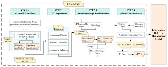
Figure 2.
An overall research methodology.
4. Forward Design Processes for Prefabricated Buildings
4.1. Analysis of Forward Design Process of Prefabricated Building
Architectural design is generally divided into three stages: scheme design, preliminary design, and construction design. Forward design is a process based on BIM technology to achieve design tasks. From the beginning of the scheme design, parameterized design, collaborative management, model optimization, and automatic drawing are directly carried out in the 3D model. Introducing this into the design of prefabricated buildings can greatly improve quality and efficiency. Figure 3 shows the overall coordination process between the BIM-based forward design method and the prefabricated building design.
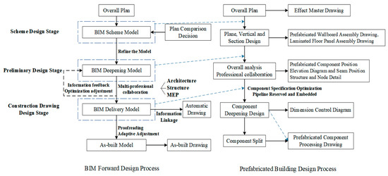
Figure 3.
Forward design process of prefabricated building.
In the scheme design stage, a rough BIM scheme model is formed after the comparative decision of the architectural planning scheme, and the plane, vertical, and section design of the building is carried out, then the prefabricated wallboard drawing and laminated floor panel drawing are generated.
In the preliminary design stage, the model is further refined to form a BIM deepening model. This stage emphasizes the collaborative design, with each specialty feeding back model information to the architectural design, then conducting overall analysis, optimization, and adjustment, and eventually determining the prefabricated component position, structure, and node details, etc.
In the construction drawing design stage, the BIM delivery model is formed. The model in this stage is mainly used to deepen the design of the components and automatically generate the detailed dimension control diagram, and then the components are split to form the prefabricated component processing drawing, and finally serve the production, construction, operation, and maintenance stages to complete the forward design of the prefabricated building.
4.2. Assembly Model Building Based on Forward Design
The purpose of constructing the information model of a prefabricated building is to regard the prefabricated building as a separable model, so as to realize the systematization of the assembly relations of prefabricated components and even embedded parts.
4.2.1. Hierarchy Establishment of Assembly Model
In the actual architectural design process, the design stages are usually not continuous, but iterative, recursive, and mixed [14]. Based on this feature, an assembly model based on forward design is established. The overall structure is shown in Figure 4. With the expansion of design depth, the prefabricated building is decomposed into several sub-assemblies or parts. When each sub-assembly completes the forward design, the forward design of the prefabricated building is completed.

Figure 4.
Overall structure of assembly model.
According to the hierarchical relations among parts, prefabricated components, and prefabricated buildings, the overall assembly is expressed in a tree-like structure, and the hierarchical distribution of prefabricated buildings is obtained, as shown in Figure 5.
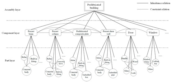
Figure 5.
Hierarchical distribution structure of assembly model.
Tree nodes represent sub-assemblies of different levels, which mainly contain their entity properties. Dotted lines between nodes indicate that one or more assembly relationships exist between components or parts. Therefore, the assembly model expresses the mixed model of hierarchy and relation, and reflects the framework of the whole 3D model.
4.2.2. Specialties Distribution of Assembly Model
The assembly model consists of three parts: architecture, structure, and MEP (electrical, HVAC, water supply and drainage). Figure 6 shows the distribution structure of the assembly model. The architectural model occupies the dominant position, and the data information generated by it is inherited and extracted by the structural and MEP professional design respectively, and the MEP design in turn inherits and extracts the data information generated by the structural model. The professional information is extracted and integrated repeatedly, and finally meets the design requirements.
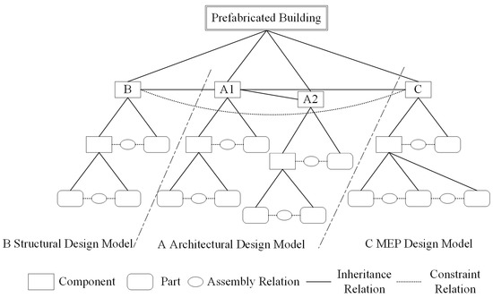
Figure 6.
Assembly model specialized distribution structure.
4.3. Assembly Knowledge Model Construction Based on Forward Design
The assembly knowledge contained in the prefabricated building is the basic knowledge that plays a guiding role. It includes:
- (1)
- The assembly requirements of the embedded parts, parts, reinforcement, and concrete body in the design and production stage of prefabricated components;
- (2)
- The technical requirements of assembly and connection between precast components and cast-in-place structures on the construction site;
- (3)
- The operation and maintenance data information of assembly components and equipment in subsequent stages.
According to the characteristics of prefabricated buildings, the assembly characteristics and assembly relations of prefabricated buildings can be further subdivided into five aspects of assembly knowledge information according to the requirements of assembly, as shown in Figure 7.
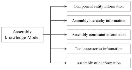
Figure 7.
Classification of assembly knowledge model information.
- Component Entity Information
Component entity information is the entity basis of model assembly, which mainly includes specific parameters such as the geometric information and physical properties of prefabricated components that constitute prefabricated buildings, and provides a necessary information basis for the subsequent assembly process.
- Assembly Hierarchy Information
The assembly hierarchy information refers to the subordinate relationship among the embedded parts, parts, prefabricated components, and the whole building that constitute the prefabricated building. It is usually expressed as a tree diagram. Assembly hierarchy information plays a key role in clarifying the assembly sequence and preventing combination errors.
- Assembly Constraint Information
Assembly constraint information is the key to complete the assembly, and it is the correct description of the relative relations between parts and parts and components, mainly including geometric constraints and physical constraints.
- Tool Accessories Information
Tool parts information refers to the information of auxiliary tools and equipment needed in each stage of a prefabricated building, such as the tool parts in the hoisting process of steel beams, lifting claws, screws, and other components in the construction stage.
- Assembly Rule Information
Assembly rule information refers to a series of specific assembly rule methods summarized in the process of the production, construction, operation, and maintenance of prefabricated buildings according to the specification requirements and from many assembly practices, including sequence, process practices, product and equipment maintenance methods, etc.
5. IFC Extension for Assembly Model and Knowledge Information
Due to the lack of unified information exchange standards, there is no effective information sharing between BIM model data and heterogeneous information in the knowledge base. The assembly model and knowledge information expression based on IFC standards can transform the assembly structure information and assembly relationship information of the model into a unified data expression mode. At the same time, the unstructured assembly knowledge information can be transformed into a structured knowledge system to realize the professional relevance and consistency between the assembly model and knowledge information.
Based on the assembly features and assembly relationships of prefabricated buildings, this paper mainly extends IFC for the component entities, attribute definitions, and association relationships of the assembly model, so as to realize the description of the assembly model architecture in the IFC standard system, as shown in Figure 8: the IFC extended EXPRESS-G diagram of the assembly model.
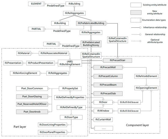
Figure 8.
EXPRESS-G diagram for extended assembly model.
Adding IFC entities is the most direct way to expand the model in the extension of IFC entity definitions. In Figure 8, the entity of a prefabricated building (IfcPrefabricatedBuilding) is a new entity. By adding this entity, the overall architecture of the assembly model is described. This entity is associated with the original building entity (IfcBuilding) through IfcRelAggregates, which is well integrated with the IFC data model and avoids ambiguity and conflict in the model system. For the component layer of the assembly model, the IFC model already has a relatively complete description system, such as door entity (IfcDoor), window entity (IfcWindow), curtain wall entity (IfcCurtain), etc. On this basis, the precast wall entity (IfcPrecastwall), precast column entity (IfcPrecastColumn), precast beam entity (IfcPrecastBeam), and precast slab entity (IfcPrecastSlab) are added. These components are derived from the building component entity (IfcBuildingElement).
For the part layer, the extension of parts can be realized by adding a property set. Take the door component as an example, as shown in Figure 8, there are newly added property sets, such as door glass window (Pset_DoorGlazing), reserved door opening (Pset_ReservedHoleofDoor), door handle (Pset_DoorKnob), etc. These multiple property sets (IfcPropertySet) are associated with multiple door entities (IfcDoors) through property relationship entities (IfcRedefinesByProperties). At the same time, the geometric element and fit relationship in the assembly relationship of the model are extended and determined through the property definitions of the material, geometry, and reinforcement information of components. Among them, the material property establishes the association between the component and the component material through the material association entity (IfcAssociatesMaterial) by the material entity (IfcMaterial). The geometric property is associated with the description entity (IfcRepresentation) by the representation property of the component. Rebar properties can establish the association of components and stiffeners (IfcReinforcingElement), including its derived rebar entity (IfcReinforcingBar) and other information through IfcRelAggregates.
For the association relationship of components, in addition to the association of door, window, and wall components relying on the opening entity mentioned above, taking beams and slabs as an example, the precast beam entity (IfcPrecastBeam) and precast slab entity (IfcPrecastSlab) can be associated based on the component association entity (IfcRelConnectsElement). The relationship between components of different disciplines can be established based on IfcRelAssignsToProduct. In addition, the connection relationship of different material parts, such as the association between reinforcement and concrete, can also be extended based on this relational entity.
Assembly knowledge information is also extended by IFC according to the above method, in which the extension methods of component entity information, assembly hierarchy information, and component association relations have been fully described, and tool accessory information is extended in the entity categories of IfcDiscreteAccessory and IfcFastener under IfcSharedComponentElements, while assembly rule information is extended in the form of property sets according to the component it belongs to. Revit software enables the representation of assembly knowledge information in BIM models.
6. An Ontology-Based Integrating Processes for IDM and MVD Development
EXPRESS language is the core of BIM model information sharing, but its incomplete semantic expression limits the description of knowledge. The integration of ontology and semantic network technology provides a method to establish and improve the knowledge system structurally and increase its reusability [37]. Transforming BIM data into formal OWL language and using the rich expression of semantic systems can better organize knowledge clearly and provide support for knowledge storage, transmission, and sharing.
6.1. BIM Ontology for Prefabricated Buildings
In construction projects, it is necessary to build relevant ontologies in multiple fields such as design, production, construction, operation, and maintenance. Building their own ontologies separately in each field will form a huge amount of concept, relationship, and other information, and the lack of shared vocabulary between fields makes the information sharing of ontologies in each field more difficult, so it is necessary to manually solve the inconsistency of concepts in each field, which is inefficient. Therefore, the above problems can be solved by constructing a shared ontology containing common concepts in multiple domains and expanding it into other domain ontologies.
- (1)
- BIM shared ontology
Parts and components are the basic components of the assembled building BIM model. Therefore, as long as the basic attributes of each part and component are clear, an assembly model can be accurately defined. According to the basic attributes of assembly components, we can build a basic BIM shared ontology. Other fields such as production or construction can build the corresponding domain ontology by expanding and adding their own attributes, so as to improve the utilization efficiency.
Taking the production stage of prefabricated building components as an example, this paper expands the shared ontology into production ontology through BIM. The internet-based ontology resources “QUDT Ontology” [38] and Free Class OWL Ontology are used to assist the description. QUDT ontology is used to describe various quantities and units of components, and FC ontology is used to describe construction materials. However, due to the particularity of the production of fabricated building components, it is used to describe production materials in this paper.
Shared ontology uses the resource description framework (RDF)/OWL language to provide a common vocabulary for the concepts of various domain ontologies. The BIM shared ontology (BIMSO) constructed in this paper aims to provide a conceptual knowledge model. Different professionals can build and use their own domain ontology to facilitate data information interaction and sharing. Figure 9 is the conceptual diagram of the BIM shared ontology, where fc:BuildingAndProductionMaterials is created by the ontology Free Class OWL Ontology (FC) and qudt_schema:Unit is established by QUTD ontology.
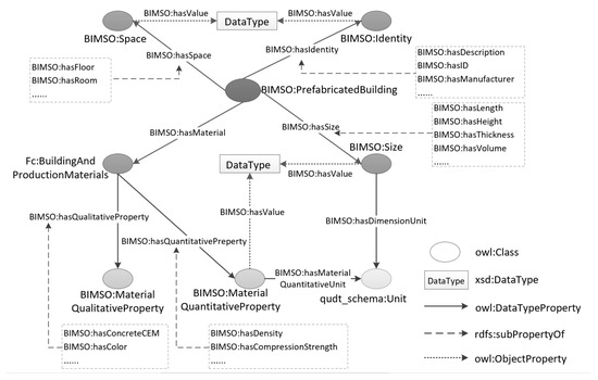
Figure 9.
Conceptual diagram of BIM shared ontology.
- (2)
- BIM production ontology
On the basis of BIM shared ontology, BIM production ontology (BIMPO) is extended, which can be applied to the field of assembly production and construction and lay a foundation for building knowledge graphs. BIMPO aims to provide a conceptual model to express the assembly knowledge information of the model in the production stage. Using RDF/OWL language, it is mainly limited to reflecting the information related to the component production process, such as attribute information including production line equipment and tools.
Figure 10 shows the BIM production ontology. By extending BIMSO:PrefabricatedBuilding and adding information related to component production (BIMSO:hasComponentProduction), the BIM production ontology (BIMPO:ProductionElement) is obtained.
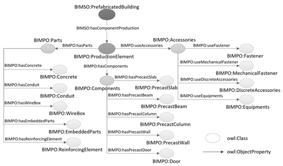
Figure 10.
Conceptual diagram of BIM production ontology.
- (3)
- Ontology Knowledge Framework of Assembly Model
The ontology-based knowledge framework system mainly includes classes, object properties, data properties, and instances. This part of the content is combed and predefined as the basis for the creation of the ontology model.
- (4)
- Classes of assembly knowledge
Class is the most basic element in the knowledge graph. The classes in the assembled building ontology model mainly include component information, part information, and accessory information. These three basic classes are represented by components, parts, and accessories, respectively, as shown in Table 1.

Table 1.
Definition of assembly knowledge base class.
- (5)
- Object properties of assembly knowledge
The object property can be defined in the knowledge graph to describe the non-hierarchical relationship between classes. For example, in the assembly model, components are composed of parts, represented by “hasParts”. In the process of production and assembly, components and parts need to use tools and accessories, represented by “useAccessories”. It can be described hierarchically in the object properties, for example, the “hasParts” property includes sub properties such as “hasConcrete”, “hasReinforcingElement”, and “hasEmbeddedParts”, which can be used to express in more detail that the precast slab component class includes the concrete body, reinforcement element (steel bar), embedded parts, and other parts.
We set the domain, range, and characteristics of these object properties. The value field defines the relationship between the start point and the end point, and the property represents the relationship between the start point and the end point. Function properties include functional, inverse functional, transitive, symmetric, antisymmetric, reflexive, and irreflexive. For example, the object property “hasParts”, whose definition field is “Components” and value field is “Parts” is functional because the object property can only connect one individual part.
- (6)
- Data properties of assembly knowledge
In the knowledge framework, the data property is used to establish the relationship between classes and data, that is, data are connected with classes through data properties. The data property and data types of knowledge information in the assembly knowledge model are analyzed. Among them, the assembly hierarchy information has been reflected in the establishment of class level, so its data property only defines part parameters. Taking the component entity information as an example, the data properties are shown in Table 2.

Table 2.
Example of component entity information data property.
- (7)
- Instances creation of assembly knowledge
Since class is an abstract concept, it is necessary to build individuals to express the specific criteria of the class. The specific cases of all classes form an instance library. An engineering project is equivalent to an instance library, and all kinds of products involved in the project process are corresponding instances. For example, for the abstract concept of the precast slab class, you can select specific slab components in the project from individual cases by adding instances under the precast slab. Table 3 shows examples of the formal expression of classes based on the network ontology language OWL.

Table 3.
OWL examples of assembly knowledge classes.
6.2. Forward Design Model View Delivery Based on Knowledge Graph
The core management goal of knowledge construction is to solve the problem of the low degree of information sharing and reuse in different disciplines and stages caused by heterogeneous data. Through knowledge construction, IDM and MVD knowledge are formalized by using the definition of knowledge category and hierarchy in an ontology semantic system, and the exchange rules and restrictions in specific fields are clarified to provide a consistent link between IDM and MVD, so as to optimize the model view delivery method, solve the problems in the current MVD development, and reduce the time and workload of developing MVD [39].
6.2.1. Ontology-Based Delivery Requirements for Prefabricated Buildings
In the process of MVD development following the NBIM standard, due to the difference between MVD developers and software suppliers, considering various actual modeling environments, the delivery requirements are inconsistent with the definition of IDM.
We establish the specific IDM of a prefabricated building based on ontology, and specify the hierarchical description related to performance implementation and business rules through the machine-readable classification of classes, subclasses, and relationships. In the ontology model, classes and instances required for the delivery process of prefabricated buildings include entities, relationships, attributes, object properties, data properties, etc. This section mainly analyzes the relationships, attributes and object properties of delivery requirements. Table 4 shows the definition of relationships, attributes, and object properties of delivery requirements based on ontology.

Table 4.
Definition of delivery requirements relationship, attributes and properties based on ontology.
- (1)
- Relationships
There are six basic types of relationships between entity objects: combination, allocation, connection, association, definition, and declaration. They are described in ontology-based delivery requirements through class relationships, as shown in Table 4. They are RelDecomposes, RelAssigns, RelConnections, RelAssociates, RelDefines, and RelDeclares, respectively.
- (2)
- Attributes
In the IFC standard, entity attributes include direct attributes, derived attributes, and inverse attributes. According to the constraints of attributes, they are divided into mandatory attributes and optional attributes. An entity must provide the value of its mandatory attributes, and the value of optional attributes can be ignored. In addition, in IFC standards, an attribute can reference multiple other entities. If the attribute is gray, it means that the attribute is not used.
- (3)
- Object Properties
Object properties are more detailed definitions of properties of entities related to construction projects according to regions and specifications. In ontology-based property descriptions, they are definitions of the object properties of construction projects. In the previous section, the object property representation of assembly hierarchy information is mentioned. This paragraph mainly describes the ontology of relevant object properties in delivery requirements for the above attributes.
The above ontology data structure is mapped and extended on the basis of IFC schema, which is convenient to convert ontology IDM into mvdXML format through IFC standard schema.
6.2.2. Delivery Model Views Based on Knowledge Graph
Due to the good organization and classification of IDM by ontology models, ontology knowledge is managed and edited through the explicit data hierarchy of Protégé software to help the effective transmission and efficient utilization of data information in the process of the project.
In the ontology model, the association between class and object properties makes the data set established by users possess certain relationship restrictions, which ensure the consistency of IDM. Using the knowledge graph and clustering in the Protégé tool, we can effectively explain the relationship between IDM ontologies, and define the concept description module for MVD. Taking the prefabricated wall component as an example, Figure 11 shows the relationship between the prefabricated wall class and the attributes class through the object properties in the ontology model.
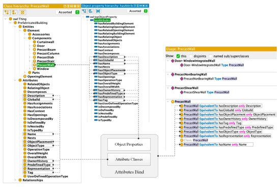
Figure 11.
Relationship between prefabricated wall class and attribute classes through object properties.
Through the visual representation of ontology, Figure 12 shows the knowledge atlas related to the prefabricated wall class and its neighborhood, as well as the relationship explored through the incremental expansion of graphics. It shows the attributes of the prefabricated wall class and added instances. In addition, the precast column class, window class, and door class are RelatedObjects of the precast wall class: the precast wall class is associated with the relation class RelAggregates through the object property isDecomposedBy. Similarly, RelAggregates is associated with precast window, so the precast wall class is associated with the precast column class. At the same time, the prefabricated wall class is connected with the opening relationship class RelVoidsElement through the object property hasRelatedOpeningElement, and then connected to the filling relationship class RelFillsElement through the entity class OpeningElement, and finally associated with the window class and door class.
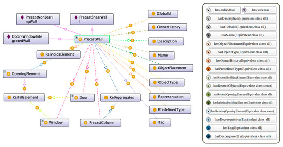
Figure 12.
Ontology relationship diagram of prefabricated wall and its domain.
In the ontology-based assembly knowledge model, when the map contains too much knowledge, the components associated through the RelAggregates tend to show complex relationships. These relationships can be managed through filtering functions or limiting some relationship types to expand the relationships to reduce the complexity of the graphics; therefore, MVD developers can effectively identify the conceptual modules required in a specific exchange scenario. As shown in Figure 13, the relationship between the RelAggregates class related to the precast slab class and its neighborhood class is shown. The associated objects of the precast wall class are represented by the object property hasRelatedObjects. RelAggregates is the key intermediary to connect these component classes. All component classes are connected to RelAggregates through the object property isDecomposedBy, and finally become the associated components of the prefabricated wall classes.

Figure 13.
Relationship between the RelAggregates class and its neighborhood class.
Designing the data filtered by properties as a conceptual description allows MVD developers to more intuitively identify the source of the conceptual description and determine the accuracy of its definition. Figure 14 shows the conceptual diagram relationship of prefabricated walls and columns associated by RelAggregates after property filtering. Therefore, establishing the data specification of IDM through the defined ontology ensures that the MVD developed based on ontology can query the concept module more efficiently.
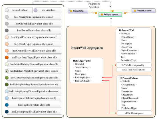
Figure 14.
Conceptual diagram of prefabricated walls and columns aggregated by RelAggregates.
In addition, because the class name of the ontology is unique, the ontology model can be used for data retrieval. Where MVD developers need to design conceptual modules with aggregation relationships, they can reuse the predefined aggregation modules shown in Figure 14. The scalability of the template can enable users in different fields to focus on the necessary exchange requirements, realize the reuse and distribution of knowledge, and greatly improve the efficiency of developing IDM and MVD.
In the forward design process of prefabricated buildings, there are multiple deliveries of models with different granularity among disciplines. Therefore, MVD concepts are reused among disciplines many times, and the model view where the same reuse concept is located also carries out data mapping of different scenes over many iterations. In the development process based on IDM and MVD, the ontology model exported in OWL/XML format can be parsed to generate concept modules, converted into mvdXML files, and imported into IfcDoc tools.
Since IfcDoc can automatically generate MVD documents, ontology-based IDM can be converted under the IFC standard according to a specific MVD. The conversion process from OWL/XML format to mvdXML includes XML expression mapping between OWL and mvdXML, an ontology language based on the IFC standard, in which class is mapped to EntityRule, and object property is mapped to AttributeRule. Figure 15 shows an example of the mapping transformation between OWL/XML and mvdXML for prefabricated wall components aggregation relations. In this mapping process, the classes GlobalId, OwnerHistory, RelAggregates, and PrecastColumn are automatically converted into the entities IfcGloballyUnqueId, IfcOwnerHistory, IfcRelAggregates, and IfcPrecastColumn, which follow the conceptual structure in IFC schema. Therefore, ontology is used as the basic model of MVD specification development to transform the format of custom tables and documents into software recognizable patterns, so as to realize the sharing and reuse of concept description and rule sets in the process of the project. The resulting mvdXML data can capture the concept template, model view, exchange requirements, and concept usage in IfcDoc.
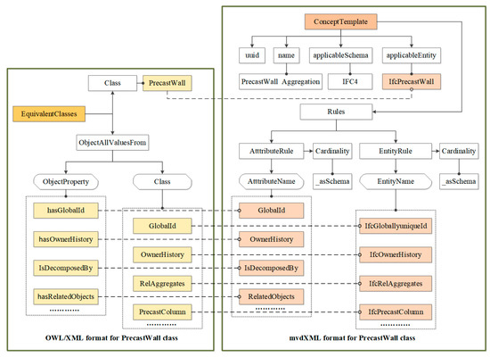
Figure 15.
Data mapping between OWL/XML and mvdXML of prefabricated wall class aggregation relationship.
7. Model Views Delivery Management of Multi-Stakeholder
The BIM forward design model supports all participants to participate in various tasks throughout the life cycle of the project, involving information exchange between different professionals and software at different stages. The realization of effective communication and cooperative management among multi-stakeholders is the key to the success of the project.
7.1. Process of Information Delivery Management of Forward Design for Prefabricated Buildings
According to the forward design process of prefabricated buildings, this section analyzes the information delivery management based on a BIM model over the whole life cycle of the project, covering the data transmission from design to production, construction, operation, and maintenance stages and among specialties, as shown in Figure 16.
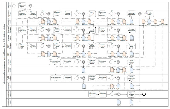
Figure 16.
Process of information delivery management of forward design for prefabricated buildings.
The design phase includes architectural design, structural design, and MEP design. First of all, the architectural designer designs the architectural scheme according to the project needs and planning of the construction unit. After examination and approval, the initial architectural scheme model A_ER.1 is formed, and the sub-models A_ER.1-S_ER.1 and A_ER.1-M_ER.1 are extracted to meet the exchange requirements of the structural and MEP specialties in the scheme design stage. Structural and MEP designers conduct their own specialty scheme design according to the model information transmitted by architectural professionals to form the structural and MEP scheme models S_ER.1 and M_ER.1. At the same time, sub-models S_ER.1-A_ER.1, S_ER.1-M_ER.1 and M_ER.1-A_ER.1, M_ER.1-S_ER.1 that meet the exchange requirements are extracted, so as to allow the transmission of models and data information coordination among professionals, and complete the design of BIM scheme model. The preliminary design and construction drawing design stages progress in the same way. Finally, the building, structure, and MEP models A_BIM, S_BIM, and M_BIM completed by collaborative design are transferred to the architectural designer for integration, and the design of BIM delivery model BIM.CO is completed.
In the production stage, the sub-model BIM.CO-P_ER.1 is extracted according to the final delivery model in the design stage. The information needed for the production of prefabricated components in the model is extracted, and the production model P_ER.1 is formed after a proofreading review with the designers, and the production model P_ER.2 is formed after adding the relevant knowledge information in the production stage. The sub-models P_ER.2-C_ER.1 and P_ER.2-O_ER.1 required in the construction and operation stages are extracted, and the final production model P_BIM is transferred to the BIM delivery model for the integration of model data and information. The construction stage and operation and maintenance stages progress in the same way, before the final model corresponding to each stage is integrated into the BIM delivery model.
7.2. Implementation Model of Information Delivery Management of Forward Design for Prefabricated Building
Based on the above information delivery process for forward design, and considering the demands of multiple stakeholders, this section proposes the implementation model of multi-stakeholder information delivery management of forward design for prefabricated buildings, as shown in Figure 17.
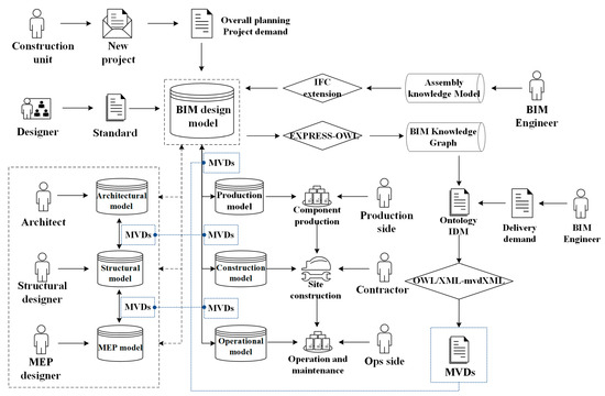
Figure 17.
Information delivery management model of forward design for prefabricated buildings.
First of all, a new project is selected by the construction unit, and the designer carries out BIM model design according to its overall planning and project demands. The BIM engineer adds knowledge information in the assembly knowledge model to the BIM design model through IFC extension, and forms the BIM knowledge graph through EXPRESS-OWL data mapping and ontology modeling. On this basis, the corresponding ontology IDM is constructed according to the delivery requirements between specialties or stages. We generate the corresponding model view MVDS through the data transformation mapping of OWL/XML-mvdXML. These model views will be used for software data transmission, and after the completion of professional collaborative design, sub-model information of subsequent stages will be extracted according to the design model. The production model guides the manufacturer to prefabricate components, the construction model guides the construction party to assemble components on site, and the operation and maintenance model guides the operation and maintenance party to operate and maintain equipment and products in the subsequent use process of the project.
8. Case Study
The case is a complex #1 office building project in Nanjing City, which has six floors. The building is L-shaped with a total construction area of 9144 square meters. It adopts a prefabricated frame structure, including prefabricated components as shown in Table 5.

Table 5.
Project Component Statistics.
8.1. Establishment of Assembly Model Based on IFC
The assembly model is established in Revit, and the structural system and maintenance system models are shown in Figure 18 and Figure 19.
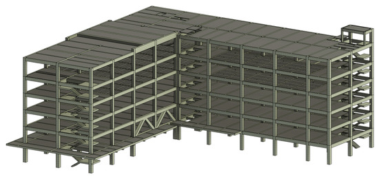
Figure 18.
Structural system of assembly model.
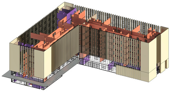
Figure 19.
Maintenance System of assembly model.
After establishing the preliminary model, based on the data structure of the IFC standard, an algorithm is used to extract the basic information of the independent component. According to the selected component type, the target component is extracted from the IFC physical file, and the final extracted IFC physical file is extended by means of the IFC entity expansion and property set expansion. In the IFC standard system, a new prefabricated building storey entity (IfcPrefabricatedBuildingStorey) and its associated entity (IfcRelContainedInSpatialStructure) and related building component entity (IfcBuildingElement) derived sub-entities are added. Table 6 lists some of the building component extension entities and property sets.

Table 6.
Example of assembled model extended component entities and property sets.
On the basis of the extracted architecture basic data information, further IFC extension of the structural and MEP professional components and parts information is carried out to form the structural design model and MEP design model. Taking the first floor of the project as an example, Figure 20 shows the application of the assembly model structure and the MEP professional IFC extension opened by IFCWebServer.
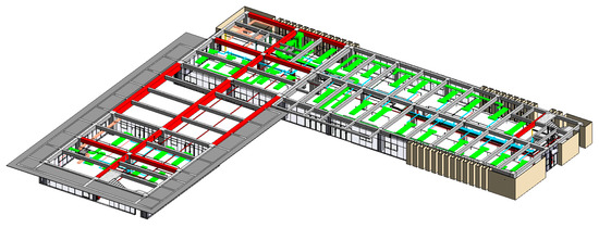
Figure 20.
Application demonstration after Structure and MEP specialties extended.
8.2. Knowledge Graph of Assembly Model
According to the conversion mapping rules between EXPRESS and OWL, the IFC-based assembly model is converted into a BIM ontology, before creating the knowledge graph in Protégé software.
8.2.1. Ontology Instance Creation
Based on the knowledge framework of the BIM shared ontology constructed in the previous section, we extend the case project and create instances. The whole project is added as an individual in the knowledge framework, where the specific components and parts correspond to the specific individuals of component class and part class, as shown in Table 7.

Table 7.
Example of class-individual mapping.
In the “PrefabricatedBuilding” class, we create an individual of this project—“No.1OfficeBuilding” (#1 Office Building); add data properties—project number, project name, project address, construction unit, design unit, production unit, construction unit, supervision unit, operation and maintenance unit, start date, construction period, and other properties; and add object properties—“hasComponents” corresponds to the components, as shown in Figure 21.
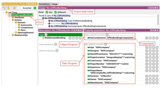
Figure 21.
Project individual creation.
In the “Components” class, we create the project components individual—“OfficeBuildingComponents”; add data properties—component entity information, assembly knowledge information, and other properties; and add object properties—“hasParts” corresponding to the parts, as shown in Figure 22.
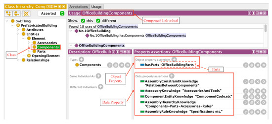
Figure 22.
Component individual creation.
In the “Accessories” class, we create a project tool accessory individual—“OfficeBuildingAccessories”. Take auxiliary equipment as an example, we create an example of equipment in the “AuxiliaryEquipment” class—“Crane” (crane); add data properties—equipment model, manufacturer, maximum lifting height, boom length, number of equipment, and other properties; and add object properties—“hasOperator” and “hasAccendant” to connect equipment operators and maintenance personnel, and other properties, as shown in Figure 23.
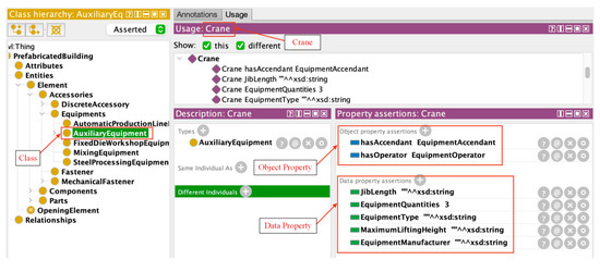
Figure 23.
Auxiliary device individual creation.
8.2.2. Visual Expression of Assembly Model Knowledge
Through the creation of instances based on the shared ontology knowledge framework, corresponding link relationships are formed among assembly items, assembly components, assembly parts, and tool accessories. Starting from the starting point of the link, each additional individual will point to another individual through the setting of object properties. The specific information about components, parts, and tool accessories is defined in each individual with corresponding data properties, which finally forms the knowledge graph of the BIM assembly model as in Figure 24.
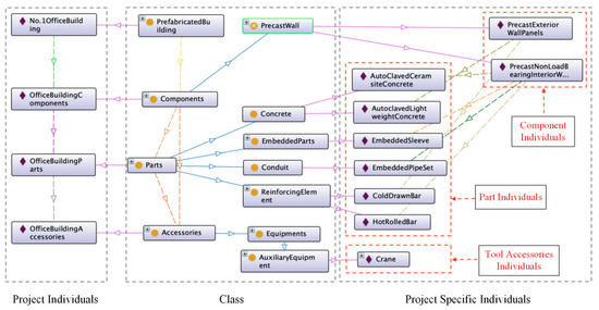
Figure 24.
Knowledge graph of BIM assembly model.
8.3. Model View Delivery of Forward Design
8.3.1. Ontology-Based IDM-MVD Delivery of Assembly Model
The ontology-based delivery model enables MVD developers to manage classes and attributes in a single knowledge graph, and the attribute-filtered data show the description and origin of the concept more intuitively. Taking the material delivery requirements of prefabricated wall components between the design and production phases as an example, Figure 25 shows the concept map associated with the material through RelAssociatesMaterial after the attribute filtering of prefabricated wall components, which can be reused when developing material association concepts for other components.
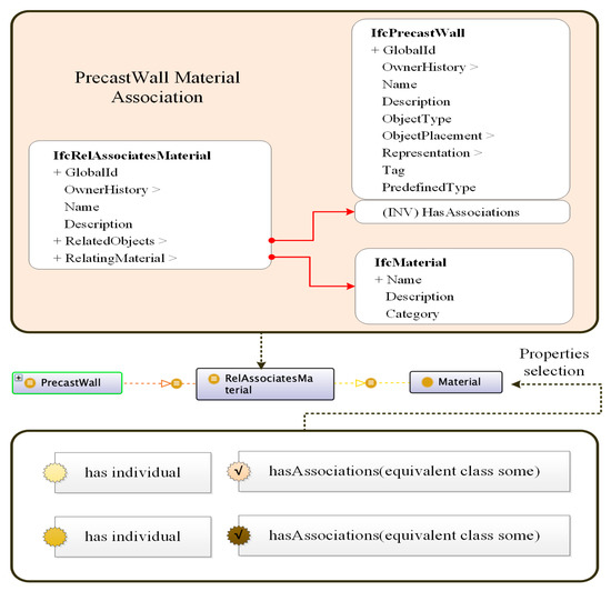
Figure 25.
Prefabricated wall components and materials conceptual drawing.
8.3.2. Data Mapping Output of Ontology Model Views
Parsing the ontology model of prefabricated wall components exported in OWL/XML format and mapping the conversion to mvdXML files for importing into the IfcDoc tool, Figure 26 shows the model view of the entities and properties associated with the prefabricated wall materials defined by the mvdXML file in the IfcDoc application. In this case, explicit attributes are presented in black, such as GlobalId; inverse attributes are presented in gray, such as hasAssignments; and black connecting lines represent semantic links, for example, GlobalId must be of the type IfcGloballyUniqueId.
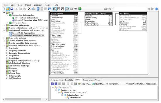
Figure 26.
Entity and property model views of material association concepts for prefabricated wall.
9. Conclusions
This paper takes the forward design of prefabricated buildings as a link, combines BIM collaborative management, the IFC standard system, assembly knowledge theory, ontology theory, IDM-MVD information delivery, and other multi-domain knowledge bases to conduct in-depth research on forward collaborative design and the model view delivery of assembly models based on IFC and ontology, and accomplishes the following work.
The complete process of BIM forward design for prefabricated building is combed. Drawing on the assembly concept of the machinery manufacturing industry, this paper designs the assembly model in terms of both layers and specialties, and expresses and extends it by IFC, which provides a reliable data standard for collaborative management among various specialties and stages. An assembly knowledge model applicable to prefabricated buildings is constructed by combining the ontology semantic system. Through knowledge extension and semantic transformation, the assembly knowledge model is expressed as an extensible ontology model, which reduces the model’s repetitive construction and improves the efficiency of knowledge information utilization. The integrated delivery of data information is analyzed from the perspective of IDM and MVD. The definition of IDM delivery demands is performed by using ontology to filter and focus the model view through the properties of the knowledge graph, and complete the model view delivery after the data mapping conversion and the view output of the official standard program IfcDoc. The method achieves the machine readability of knowledge information, avoids heterogeneity and redundancy of information demands and expression rules, and provides a new idea of efficient model view delivery.
Forward collaborative design of the building whole life cycle is a huge and complex process. This paper theoretically illustrates the feasibility of the forward design of prefabricated buildings with model view delivery as the core, but there are still many problems to be further explored in practical application. This paper presents a detailed analysis of language mapping methods in terms of language systems and semantic rules; in the future, the corresponding procedures can be fully utilized or extended to achieve the automatic conversion of languages or formats, and improve the efficiency and accuracy of mapping. The MVD output of the model view delivery method constructed in this paper still needs to be further developed and applied in software, then the information interaction can finally be realized in a specific field.
Author Contributions
Conceptualization, Z.X. and H.Z.; methodology, Z.X., J.W. and H.Z; software, J.W. and H.Z.; investigation, J.W. and H.Z.; writing—original draft preparation, Z.X., J.W. and H.Z.; writing—review and editing, Z.X., J.W. and H.Z.; visualization, J.W. and H.Z.; funding acquisition, Z.X. All authors have read and agreed to the published version of the manuscript.
Funding
This work was supported by the National Natural Science Foundation of China (NSFC-72071043), the Natural Science Foundation of Jiangsu Province (BK20201280), and the MOE (Ministry of Education in China) Project of Humanities and Social Sciences (20YJAZH114).
Data Availability Statement
Data are contained within the article. Additional supporting data presented in this study are available on request from the corresponding author.
Conflicts of Interest
The authors declare no conflict of interest.
References
- Masood, R.; Lim, J.B.P.; González, V.A.; Roy, K.; Khan, K.I.A. A Systematic Review on Supply Chain Management in Prefabricated House-Building Research. Buildings 2022, 12, 40. [Google Scholar] [CrossRef]
- Zhang, J.; Long, Y.; Lv, S.; Xiang, Y. BIM-enabled modular and industrialized construction in China. Procedia Eng. 2016, 145, 1456–1461. [Google Scholar] [CrossRef]
- Tan, T.; Chen, K.; Xue, F.; Lu, W. Barriers to Building Information Modeling (BIM) implementation in China’s prefabricated construction: An interpretive structural modeling (ISM) approach. J. Clean. Prod. 2019, 219, 949–959. [Google Scholar] [CrossRef]
- Pruskova, K.; Kaiser, J. Implementation of BIM Technology into the Design Process Using the Scheme of BIM Execution Plan. IOP Conf. Ser. Mater. Sci. Eng. 2019, 471, 022019. [Google Scholar] [CrossRef]
- East, W.E. An Overview of the US National building Information Model Standard (NBIMS). Comput. Civ. Eng. 2007, 59–66. [Google Scholar] [CrossRef]
- Eadie, R.; Browne, M.; Odeyinka, H.; McKeown, C.; McNiff, S. BIM implementation throughout the UK construction prodateject lifecycle: An analysis. Autom. Constr. 2013, 36, 145–151. [Google Scholar] [CrossRef]
- Ma, Z.; Zhang, D.; Li, J. A dedicated collaboration platform for Integrated Project Delivery. Autom. Constr. 2018, 86, 199–209. [Google Scholar] [CrossRef]
- Asmi, E.; Robert, S.; Haas, B.; Zreik, K. A standardized approach to BIM and energy simulation connection. Int. J. Des. Sci. Technol. 2015, 21, 59–82. [Google Scholar]
- Yuan, Q. Research On BIM Design Standard of Prefabricated Building. Int. J. Educ. Econ. 2021, 4, 4. [Google Scholar]
- Jiang, D.; Na, G.; Ji, K. Research on Assembly Model Based on Assembly Constraints Transformation. Procedia Eng. 2012, 29, 770–774. [Google Scholar] [CrossRef][Green Version]
- Kim, K.-Y.; Manley, D.G.; Yang, H. Ontology-based assembly design and information sharing for collaborative product development. Comput. Des. 2006, 38, 1233–1250. [Google Scholar] [CrossRef]
- Rachuri, S.; Han, Y.H.; Foufou, S.; Feng, S.C.; Roy, U.; Wang, F.; Sriram, R.D.; Lyons, K.W. A model for capturing product assembly information. J. Comput. Inf. Sci. Eng. 2006, 6, 11–21. [Google Scholar] [CrossRef][Green Version]
- Zhao, S.; Hong, J.; Zhao, H.; Li, S.; Ding, L. Research on assembly sequence planning method for large-scale assembly based on an integrated assembly model. Proc. Inst. Mech. Eng. Part B J. Eng. Manuf. 2012, 226, 733–744. [Google Scholar] [CrossRef]
- Chen, X.; Gao, S.; Yang, Y.; Zhang, S. Multi-level assembly model for top-down design of mechanical products. Comput. Aided Des. 2012, 44, 1033–1048. [Google Scholar] [CrossRef]
- Zhang, J.; Xu, Z.; Li, Y.; Jiang, S. Framework for the integration of assembly modeling and simulation based on assembly feature pair. Int. J. Adv. Manuf. Technol. 2015, 78, 765–780. [Google Scholar] [CrossRef]
- Lou, J.; Lu, W.; Xu, J.; Li, X.; Wang, J. Nomenclature for offsite construction. Build. Res. Inf. 2022, 2, 1–15. [Google Scholar] [CrossRef]
- Xu, Z.; Wang, X.; Zhou, W.; Yuan, J. Study on the Evaluation Method of Green Construction Based on Ontology and BIM. Adv. Civ. Eng. 2019, 2019, 5650463. [Google Scholar] [CrossRef]
- Terkaj, W.; Šojić, A. Ontology-based representation of IFC express rules: An enhancement of the ifc owl ontology. Autom. Constr. 2015, 57, 188–201. [Google Scholar] [CrossRef]
- Pauwels, P.; Terkaj, W. Express to owl for construction industry: Towards a recommendable and usable ifc owl ontology. Autom. Constr. 2016, 63, 100–133. [Google Scholar] [CrossRef]
- Pauwels, P.; De Farias, T.M.; Zhang, C.; Roxin, A.; Beetz, J.; De Roo, J.; Nicolle, C. A performance benchmark over semantic rule checking approaches in construction industry. Adv. Eng. Inform. 2017, 33, 68–88. [Google Scholar] [CrossRef]
- Zhong, B.; Gan, C.; Luo, H.; Xing, X. Ontology-based framework for building environmental monitoring and compliance checking under BIM environment. Build. Environ. 2018, 141, 127–142. [Google Scholar] [CrossRef]
- De Farias, T.M.; Roxin, A.; Nicolle, C. A rule-based methodology to extract building model views. Autom. Constr. 2018, 92, 214–229. [Google Scholar] [CrossRef]
- Venugopal, M.; Eastman, C.M.; Sacks, R.; Teizer, J. Semantics of model views for information exchanges using the industry foundation class schema. Adv. Eng. Inform. 2012, 26, 411–428. [Google Scholar] [CrossRef]
- Eastman, C.; Sacks, R. Introducing a new methodology to develop the information delivery manual for AEC projects. In Proceedings of the CIB W78 2010: 27th International Conference, Cairo, Egypt, 16–19 November 2010; pp. 16–18. [Google Scholar]
- Eastman, C.M.; Jeong, Y.S.; Sacks, R.; Kaner, I. Exchange model and exchange object concepts for implementation of national BIM standards. J. Comput. Civ. Eng. 2010, 24, 25–34. [Google Scholar] [CrossRef]
- Zhang, C.; Beetz, J.; Weise, M. Interoperable validation for IFC building models using open standards. J. Inf. Technol. Constr. 2015, 20, 24–39. [Google Scholar]
- Lee, Y.C.; Eastman, C.M.; Lee, J.K. Validations for ensuring the interoperability of data exchange of a building information model. Autom. Constr. 2015, 58, 176–195. [Google Scholar] [CrossRef]
- Arayici, Y.; Fernando, T.; Munoz, V.; Bassanino, M. Interoperability specification development for integrated BIM use in performance based design. Autom. Constr. 2018, 85, 167–181. [Google Scholar] [CrossRef]
- Jeong, Y.S.; Eastman, C.M.; Sacks, R.; Kaner, I. Benchmark tests for BIM data exchanges of precast concrete. Autom. Constr. 2009, 18, 469–484. [Google Scholar] [CrossRef]
- Aram, S.; Eastman, C.; Sacks, R. Requirements for BIM platforms in the concrete reinforcement supply chain. Autom. Constr. 2013, 35, 1–17. [Google Scholar] [CrossRef]
- East, E.W.; Nisbet, N.; Liebich, T. Facility management handover model view. J. Comput. Civ. Eng. 2013, 27, 61–67. [Google Scholar] [CrossRef]
- Lee, G. Concept-Based Method for Extracting Valid Subsets from an Express Schema. J. Comput. Civ. Eng. 2009, 23, 128–135. [Google Scholar] [CrossRef]
- Won, J.; Lee, G.; Cho, C. No-Schema Algorithm for Extracting a Partial Model from an IFC Instance Model. J. Comput. Civ. Eng. 2013, 27, 585–592. [Google Scholar] [CrossRef]
- Lee, Y.C.; Eastman, C.M.; Solihin, W.; See, R. Modularized rule-based validation of a BIM model pertaining to model fviews. Autom. Constr. 2016, 63, 1–11. [Google Scholar] [CrossRef]
- Pinheiro, S.; Wimmer, R.; O’Donnell, J.; Muhic, S.; Bazjanac, V.; Maile, T.; Frisch, J.; van Treeck, C. MVD based information exchange between BIM and building energy performance simulation. Autom. Constr. 2018, 90, 91–103. [Google Scholar] [CrossRef]
- Jiang, S.; Wu, Z.; Zhang, B.; Cha, H.S. Combined MvdXML and Semantic Technologies for Green Construction Code Checking. Appl. Sci. 2019, 9, 1463. [Google Scholar] [CrossRef]
- Anumba, C.J.; Issa, R.R.; Pan, J.; Mutis, I. Ontology-based information and knowledge management in construction. Constr. Innov. 2008, 8, 218–239. [Google Scholar] [CrossRef]
- Theissen, L.J.; Kröger, M.; Heinrichs, B.; Decker, S. LISSU: Continuous Monitoring of SOA Communication with Constraint-Based Validation. SN Comput. Sci. 2022, 3, 293. [Google Scholar] [CrossRef]
- Lee, Y.C.; Eastman, C.M.; Solihin, W. An ontology-based approach for developing data exchange requirements and model views of building information modeling. Adv. Eng. Inform. 2016, 30, 354–367. [Google Scholar] [CrossRef]
Publisher’s Note: MDPI stays neutral with regard to jurisdictional claims in published maps and institutional affiliations. |
© 2022 by the authors. Licensee MDPI, Basel, Switzerland. This article is an open access article distributed under the terms and conditions of the Creative Commons Attribution (CC BY) license (https://creativecommons.org/licenses/by/4.0/).