
Structural Analysis and Design of Sustainable Cross-Laminated Timber Foundation Walls

 , and
, and
Abstract
:1. Introduction
2. Sustainability Considerations
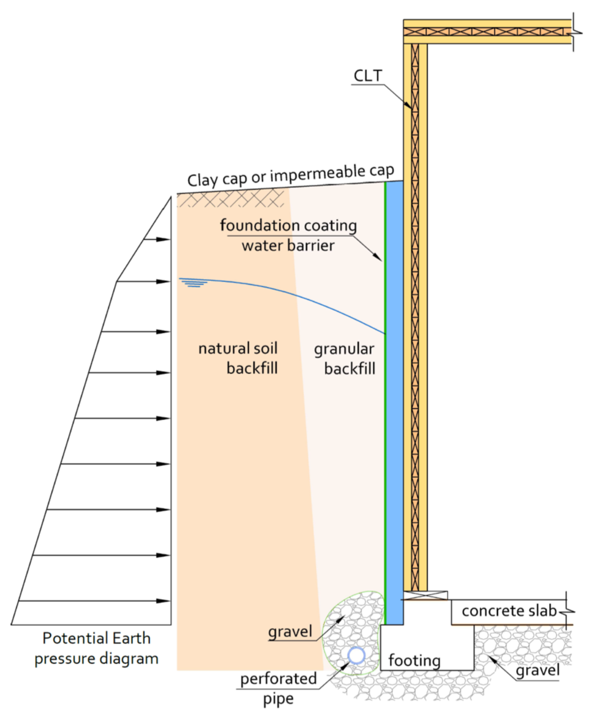
3. Geothermal and Hygrothermal Considerations
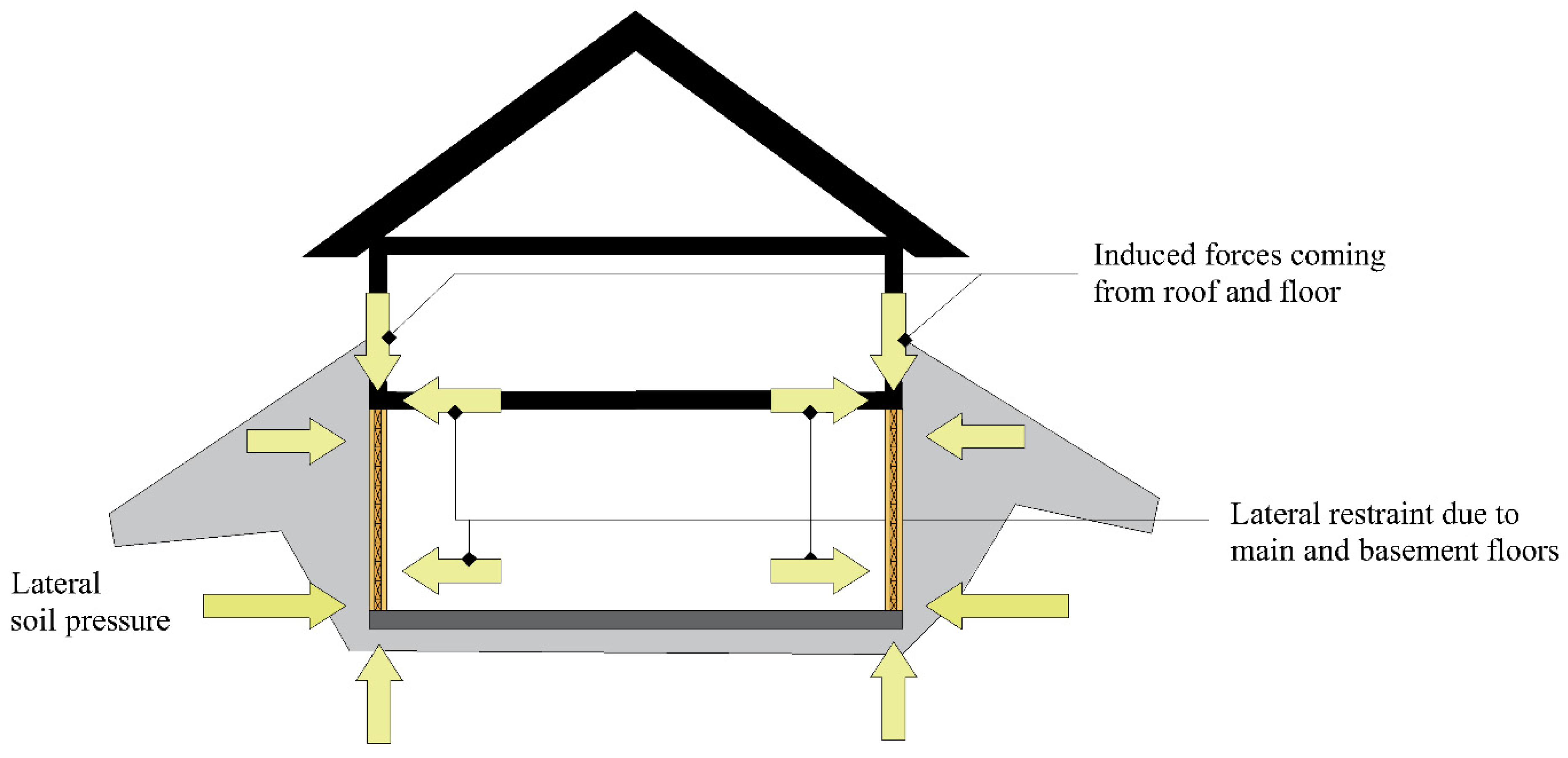
4. Structural Analysis and Design
4.1. Design Objective, Methodology, and Design Loads
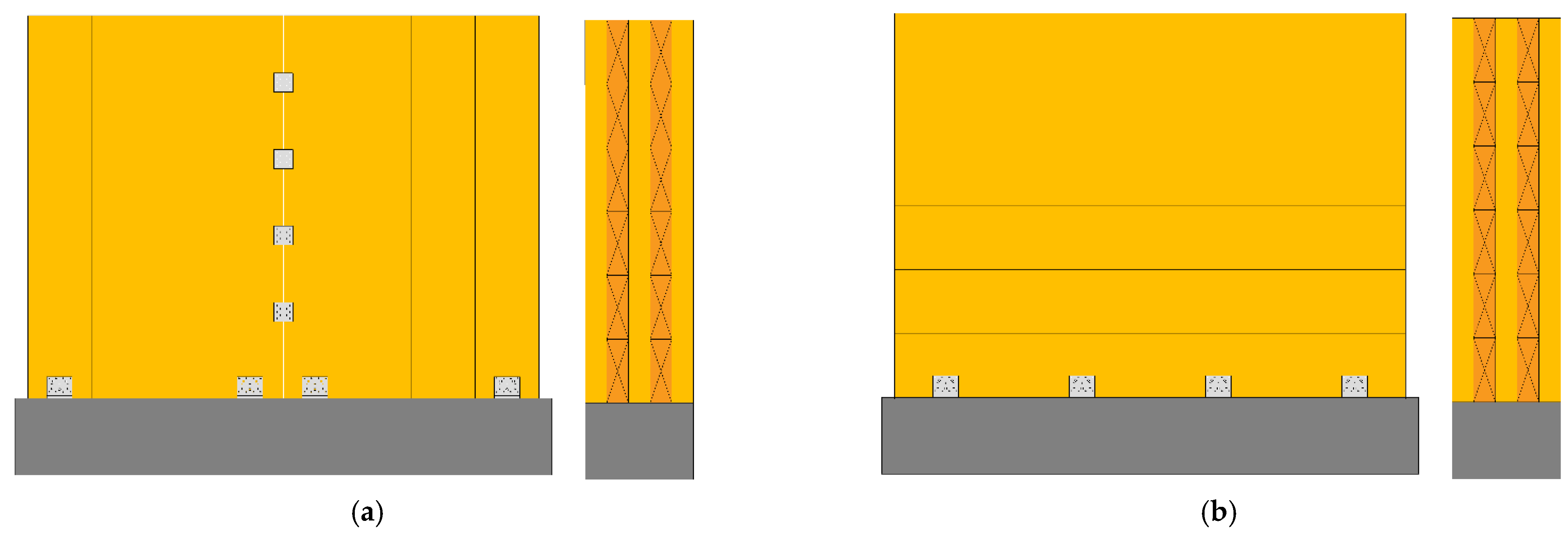
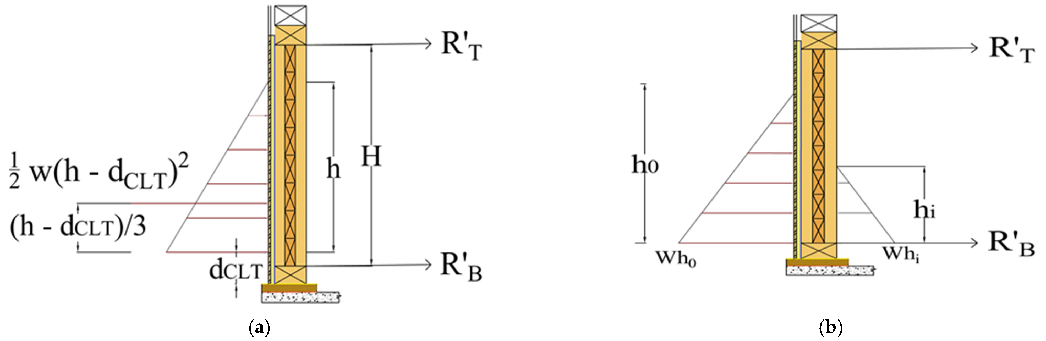
4.2. CLT Panel Analysis and Design
4.2.1. Ultimate Limit States
4.2.2. Serviceability Limit States
4.2.3. Pre-Engineered Selection Tables
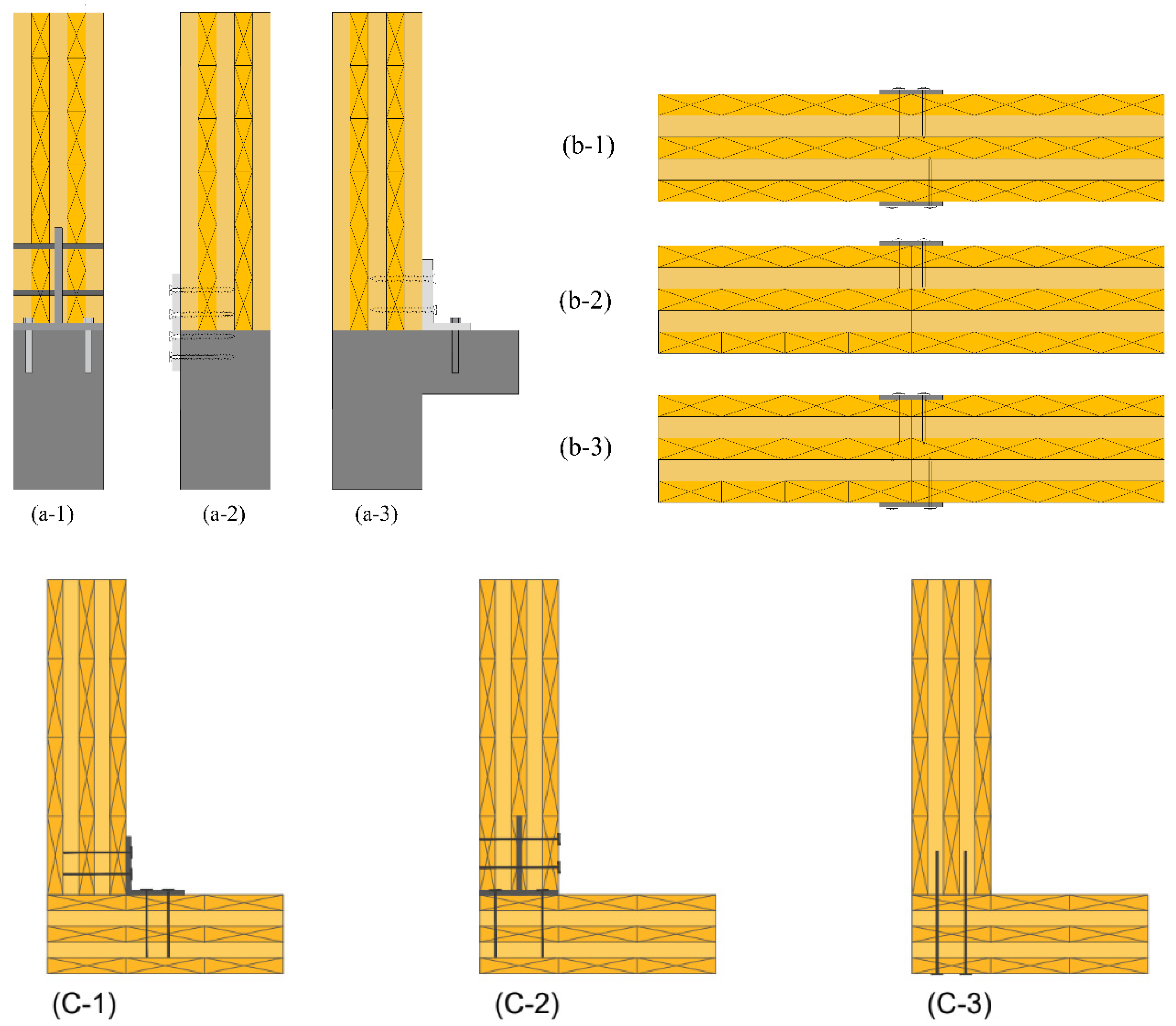
4.3. Connections
4.4. Design Verification
5. Summary and Conclusions
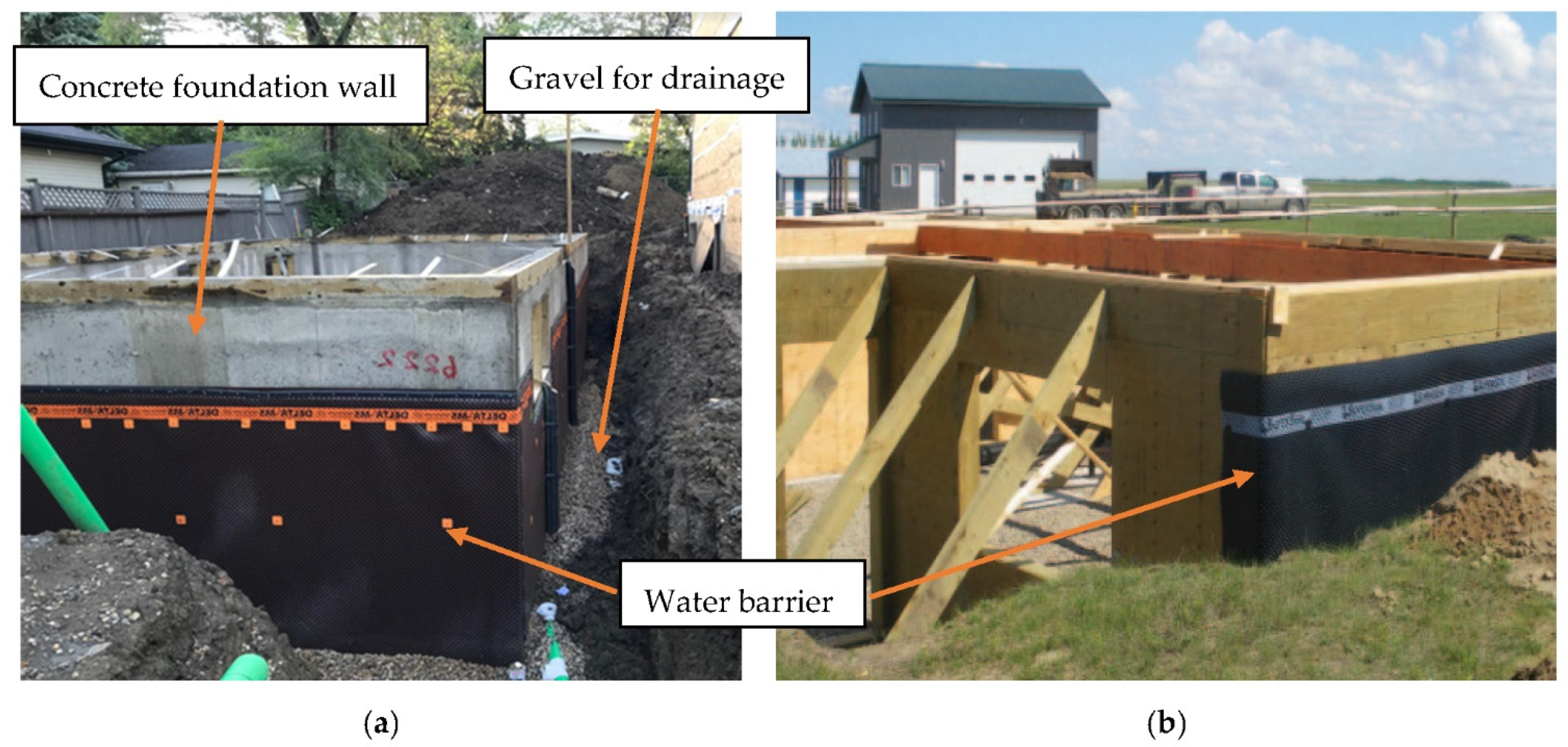
- Cross-laminated timber (CLT) can be used as an alternative solution for concrete foundation walls, commonly used in low-rise residential buildings. This solution may overcome the issues that inherently exist when using concrete for such applications, such as cracking and possibility of water penetration, high thermal loss, long construction time, feeling of dampness, mold and mildew growth, problems with construction at low temperatures, difficulty of construction in remote locations, and difficulty of finishing within the construction time.
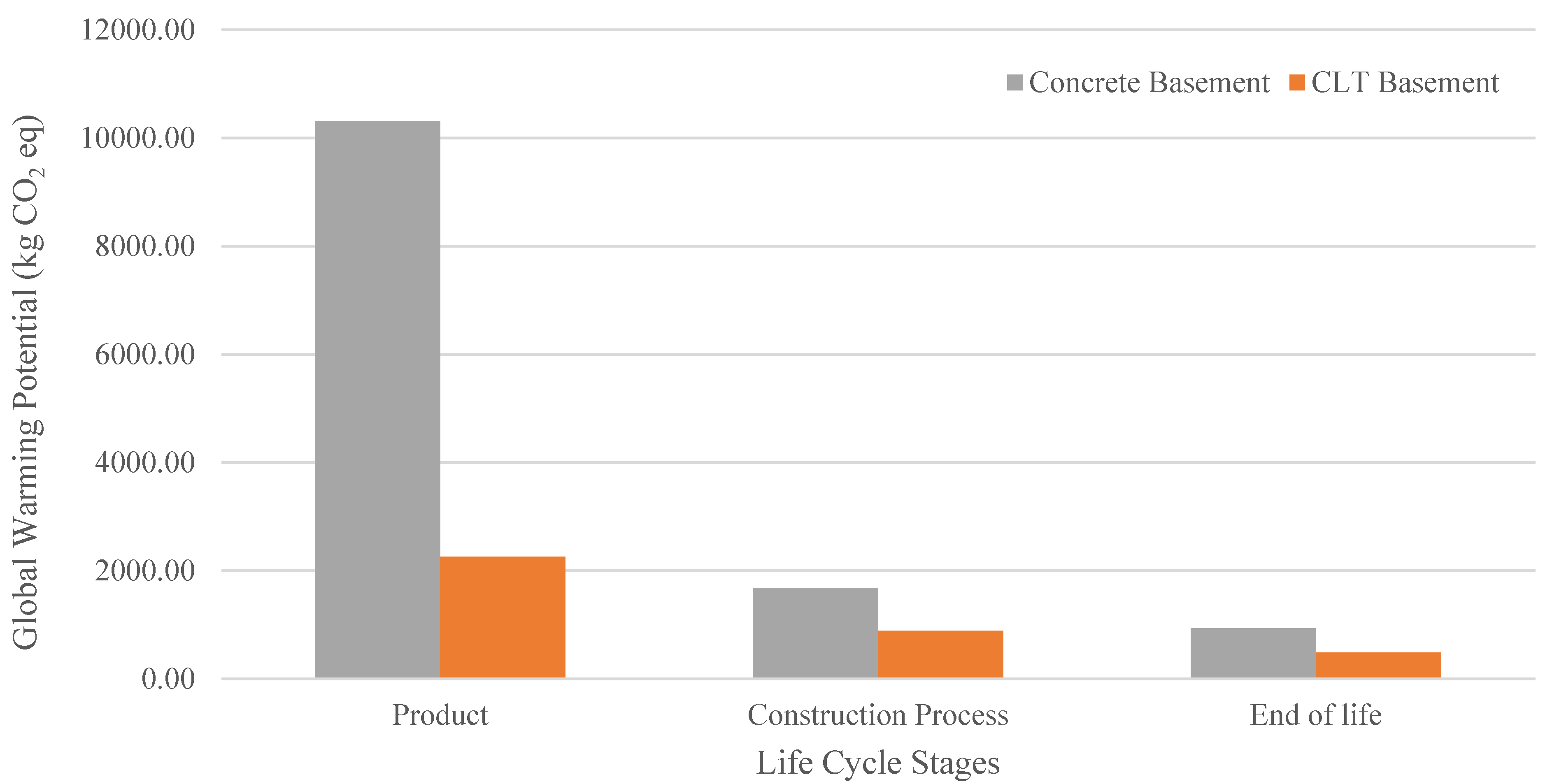
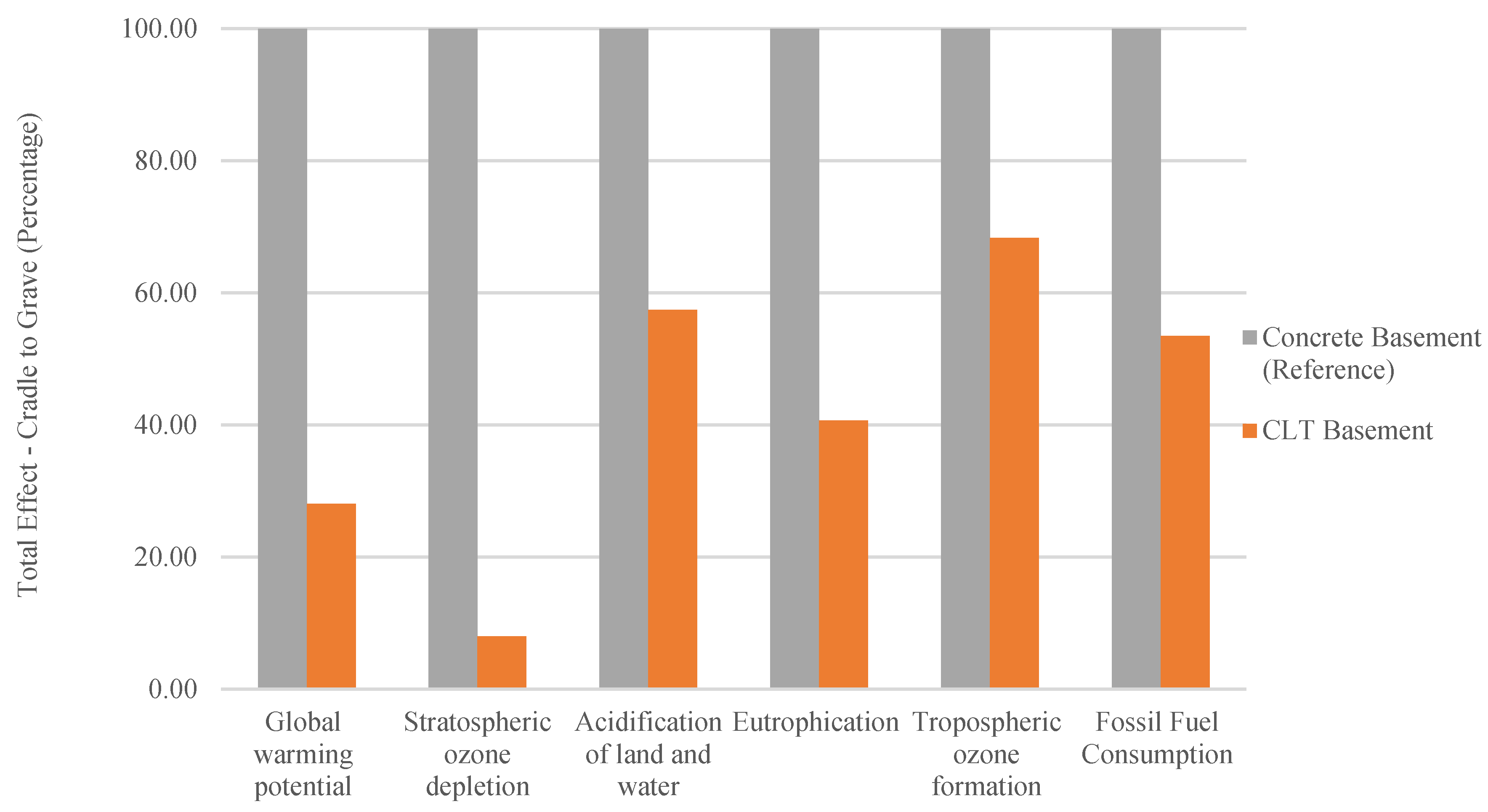
- When compared to equivalent concrete systems, CLT foundation walls can significantly improve all environmental measures, such as acidification potential and global warming potential.
- For various scenarios, including soil type and backfill height, a simplified analysis procedure for designing laminate thicknesses and the standardized number of layers in CLT basement walls was discussed. The results were presented in the form of pre-engineered design tables. These tables are provided to replace existing reinforced concrete foundation walls commonly used in low-rise construction. Advanced finite element analysis was performed on sample architypes to validate the simplified analysis procedure used for design. It was shown that the proposed analysis procedure and the calculated pre-engineered tables produce conservative and efficient results.
- Depending on the soil type and backfill height, 3–7-ply CLT panels are sufficient for net wall heights of up to 3 m in the vertical arrangement. In general, three-ply CLT was deemed sufficient for most anticipated cases. However, using a horizontal arrangement, five-ply CLT is required as a minimum. As a result, for economic reasons, it is suggested to use CLT in the vertical arrangement.
- Designing very stiff panel-to-panel connections in the vertical arrangement will assure the designers of the panels’ structural integrity and prevent potential water penetration problems at the connection locations. Detailed modeling of panel-to-panel connections did not seem to change the results significantly.
Author Contributions
Funding
Institutional Review Board Statement
Informed Consent Statement
Data Availability Statement
Acknowledgments
Conflicts of Interest
Appendix A

| Maximum Wall Height (m) | Maximum Backfill Height (m) | Maximum Inside Backfill Height (m) | Soil Classes | |||||||
|---|---|---|---|---|---|---|---|---|---|---|
| GW, GP, GM, SW, SP | GC, SM | SM-SC, SC, ML, ML-CL | CL | |||||||
| Number | Thickness | Number | Thickness | Number | Thickness | Number | Thickness | |||
| 1.5 | 1.2–1.5 | 0.5–1.2 | 3 | 87 | 3 | 87 | 3 | 87 | 3 | 87 |
| 1.8 | 1.2–1.8 | 0.5–1.5 | 3 | 87 | 3 | 87 | 3 | 87 | 3 | 87 |
| 2 | 1.2–2 | 0.5–1.8 | 3 | 87 | 3 | 87 | 3 | 87 | 3 | 87 |
| 2.2 | 1.2–1.8 | 0.5–1.2 | 3 | 87 | 3 | 87 | 3 | 87 | 3 | 87 |
| 2–2.2 | 0.5–2 | 3 | 87 | 3 | 87 | 3 | 87 | 3 | 87 | |
| 2.4 | 1.2–1.5 | 0.5–1.2 | 3 | 87 | 3 | 87 | 3 | 87 | 3 | 87 |
| 1.8 | 0.5- 1.5 | 3 | 87 | 3 | 87 | 3 | 87 | 5 | 139 | |
| 2 | 0.5–2 | 3 | 87 | 3 | 87 | 3 | 87 | 5 | 139 | |
| 2.2–2.4 | 0.5–2.2 | 3 | 87 | 3 | 87 | 5 | 139 | 5 | 139 | |
| 2.7 | 1.2 | 0.5–1 | 3 | 87 | 3 | 87 | 3 | 87 | 3 | 87 |
| 1.5–2 | 0.5–1.8 | 3 | 87 | 3 | 87 | 5 | 139 | 5 | 139 | |
| 2.2–2.4 | 0.5–2.2 | 3 | 87 | 3 | 87 | 5 | 139 | 5 | 139 | |
| 3 | 1.2–1.8 | 0.5–1.5 | 3 | 87 | 3 | 87 | 5 | 139 | 5 | 139 |
| 2–2.2 | 0.5–2 | 3 | 87 | 5 | 139 | 5 | 139 | 5 | 139 | |
| Crawl Space Design | ||||||||||
| 2.7 | 2.7 | 0.5–2.4 | 3 | 87 | 3 | 87 | 5 | 139 | 5 | 139 |
| 3 | 2.4 | 0.5–2.2 | 5 | 139 | 5 | 139 | 5 | 139 | 5 | 139 |
| 2.7 | 0.5–2.2 | 5 | 139 | 5 | 139 | 5 | 139 | 5 | 139 | |
| 3 | 0.5–2.7 | 5 | 139 | 5 | 139 | 5 | 139 | 5 | 139 | |
| Basement Wall Design | ||||||||||
| 2.7 | 2.7 | 0 | 3 | 87 | 5 | 139 | 5 | 139 | 5 | 139 |
| 3 | 2.7 | 0 | 3 | 87 | 5 | 139 | 5 | 139 | 7 | 191 |
| 3 | 0 | 5 | 139 | 5 | 139 | 7 | 191 | 7 | 191 | |
| Maximum Wall Height (m) | Maximum Backfill Height (m) | Maximum Inside Backfill Height (m) | Soil Classes | |||||||
|---|---|---|---|---|---|---|---|---|---|---|
| GW, GP, GM, SW, SP | GC, SM | SM-SC, SC, ML, ML-CL | CL | |||||||
| No. Layers | Thickness | No. Layers | Thickness | No. Layers | Thickness | No. Layers | Thickness | |||
| 1.5 | 1.2–1.5 | 0.5–1.2 | 3 | 87 | 3 | 87 | 3 | 87 | 3 | 87 |
| 1.8 | 1.2–1.8 | 0.5–1.5 | 3 | 87 | 3 | 87 | 3 | 87 | 3 | 87 |
| 2 | 1.2–2 | 0.5–1.8 | 3 | 87 | 3 | 87 | 3 | 87 | 3 | 87 |
| 2.2 | 1.2–1.8 | 0.5- 1.2 | 3 | 87 | 3 | 87 | 3 | 87 | 3 | 87 |
| 2–2.2 | 0.5–2 | 3 | 87 | 3 | 87 | 3 | 87 | 5 | 139 | |
| 2.4 | 1.2–1.5 | 0.5–1.2 | 3 | 87 | 3 | 87 | 3 | 87 | 3 | 87 |
| 1.8 | 0.5–1.5 | 3 | 87 | 3 | 87 | 3 | 87 | 5 | 139 | |
| 2–2.4 | 0.5–2.2 | 3 | 87 | 3 | 87 | 5 | 139 | 5 | 139 | |
| 2.7 | 1.2 | 0.5–1 | 3 | 87 | 3 | 87 | 3 | 87 | 5 | 139 |
| 1.5–2.4 | 0.5–2.2 | 3 | 87 | 3 | 87 | 5 | 139 | 5 | 139 | |
| 2.7 | 0.5–2.4 | 3 | 87 | 5 | 139 | 5 | 139 | 5 | 139 | |
| 3 | 1.2–1.8 | 0.5–1.5 | 3 | 87 | 3 | 87 | 5 | 139 | 5 | 139 |
| 2–2.2 | 0.5–2 | 3 | 87 | 5 | 139 | 5 | 139 | 5 | 139 | |
| 2.4–2.7 | 0.5–2.4 | 5 | 139 | 5 | 139 | 5 | 139 | 5 | 139 | |
| 3 | 0.5–2.7 | 5 | 139 | 5 | 139 | 5 | 139 | 7 | 191 | |
| Maximum Wall Height (m) | Maximum Backfill Height (m) | Maximum Inside Backfill Height (m) | Soil Classes | |||||||
|---|---|---|---|---|---|---|---|---|---|---|
| GW, GP, GM, SW, SP | GC, SM | SM-SC, SC, ML, ML-CL | CL | |||||||
| No. Layers | Thickness | No. Layers | Thickness | No. Layers | Thickness | No. Layers | Thickness | |||
| 1.5 | 1.2–1.5 | 0.5–1.2 | 3 | 87 | 3 | 87 | 3 | 87 | 3 | 87 |
| 1.8 | 1.2–1.8 | 0.5–1.5 | 3 | 87 | 3 | 87 | 3 | 87 | 3 | 87 |
| 2 | 1.2–2 | 0.5–1.8 | 3 | 87 | 3 | 87 | 3 | 87 | 3 | 87 |
| 2.2 | 1.2–1.5 | 0.5- 1.2 | 3 | 87 | 3 | 87 | 3 | 87 | 3 | 87 |
| 1.8 | 0.5–1.5 | 3 | 87 | 3 | 87 | 3 | 87 | 5 | 139 | |
| 2–2.2 | 0.5–2 | 3 | 87 | 3 | 87 | 5 | 139 | 5 | 139 | |
| 2.4 | 1.2 | 0.5–1 | 3 | 87 | 3 | 87 | 3 | 87 | 3 | 87 |
| 1.5–2.4 | 0.5–2.2 | 3 | 87 | 3 | 87 | 5 | 139 | 5 | 139 | |
| 2.7 | 1.2–1.8 | 0.5–1.5 | 3 | 87 | 3 | 87 | 5 | 139 | 5 | 139 |
| 2–2.4 | 0.5–1.2 | 3 | 87 | 5 | 139 | 5 | 139 | 5 | 139 | |
| 3 | 1.2 | 0.5–1 | 3 | 87 | 3 | 87 | 5 | 139 | 5 | 139 |
| 1.5–1.8 | 0.5–1.5 | 3 | 87 | 5 | 139 | 5 | 139 | 5 | 139 | |
| 2–2.2 | 0.5–2 | 5 | 139 | 5 | 139 | 5 | 139 | 5 | 139 | |
| Crawl Space Design | ||||||||||
| 2.7 | 2.7 | 0.5–2.4 | 5 | 139 | 5 | 139 | 5 | 139 | 5 | 139 |
| 3 | 2.4 | 0.5–2.2 | 5 | 139 | 5 | 139 | 5 | 139 | 7 | 191 |
| 2.7 | 0.5–2.4 | 5 | 139 | 5 | 139 | 5 | 139 | 7 | 191 | |
| 3 | 0.5–2.7 | 5 | 139 | 5 | 139 | 5 | 139 | 7 | 191 | |
| Basement Wall Design | ||||||||||
| 2.7 | 2.7 | 0 | 5 | 139 | 5 | 139 | 5 | 139 | 7 | 191 |
| 3 | 2.4 | 0 | 5 | 139 | 5 | 139 | 5 | 139 | 7 | 191 |
| 2.7 | 0 | 5 | 139 | 5 | 139 | 7 | 191 | 7 | 191 | |
| 3 | 0 | 5 | 139 | 5 | 139 | 7 | 191 | 7 | 191 | |
| Maximum Wall Height (m) | Maximum Backfill Height (m) | Maximum Inside Backfill Height (m) | Soil Classes | |||||||
|---|---|---|---|---|---|---|---|---|---|---|
| GW, GP, GM, SW, SP | GC, SM | SM-SC, SC, ML, ML-CL | CL | |||||||
| No. Layers | Thickness | No. Layers | Thickness | No. Layers | Thickness | No. Layers | Thickness | |||
| 1.5 | 1.2–1.5 | 0.5–1.2 | 3 | 87 | 3 | 87 | 3 | 87 | 3 | 87 |
| 1.8 | 1.2–1.8 | 0.5–1.5 | 3 | 87 | 3 | 87 | 3 | 87 | 3 | 87 |
| 2 | 1.2–2 | 0.5–1.8 | 3 | 87 | 3 | 87 | 3 | 87 | 3 | 87 |
| 2.2 | 1.2–1.8 | 0.5–1.2 | 3 | 87 | 3 | 87 | 3 | 87 | 3 | 87 |
| 2–2.2 | 0.5–2 | 3 | 87 | 3 | 87 | 3 | 87 | 5 | 139 | |
| 2.4 | 1.2–1.5 | 0.5–1.2 | 3 | 87 | 3 | 87 | 3 | 87 | 3 | 87 |
| 1.8 | 0.5–1.5 | 3 | 87 | 3 | 87 | 3 | 87 | 5 | 139 | |
| 2–2.4 | 0.5–2.2 | 3 | 87 | 3 | 87 | 5 | 139 | 5 | 139 | |
| 2.7 | 1.2 | 0.5–1 | 3 | 87 | 3 | 87 | 3 | 87 | 5 | 139 |
| 1.5–2.4 | 0.5–2.2 | 3 | 87 | 3 | 87 | 5 | 139 | 5 | 139 | |
| 2.7 | 0.5–2.4 | 3 | 87 | 5 | 139 | 5 | 139 | 5 | 139 | |
| 3 | 1.2–1.8 | 0.5–1.5 | 3 | 87 | 3 | 87 | 5 | 139 | 5 | 139 |
| 2–2.2 | 0.5–2 | 3 | 87 | 5 | 139 | 5 | 139 | 5 | 139 | |
| 2.4–2.7 | 0.5–2.4 | 5 | 139 | 5 | 139 | 5 | 139 | 5 | 139 | |
| Crawl Space Design | ||||||||||
| 3 | 3 | 0.5–1 | 5 | 139 | 5 | 139 | 7 | 191 | 7 | 191 |
| 1–2.7 | 5 | 139 | 5 | 139 | 5 | 139 | 7 | 191 | ||
| Basement Wall Design | ||||||||||
| 3 | 3 | 0 | 5 | 139 | 5 | 139 | 7 | 191 | 7 | 191 |
| Maximum Wall Height (m) | Maximum Backfill Height (m) | Maximum Inside Backfill Height (m) | Soil Classes | |||||||
|---|---|---|---|---|---|---|---|---|---|---|
| GW, GP, GM, SW, SP | GC, SM | SM-SC, SC, ML, ML-CL | CL | |||||||
| No. Layers | Thickness | No. Layers | Thickness | No. Layers | Thickness | No. Layers | Thickness | |||
| 1.5 | 1.2–1.5 | 0.5–1.2 | 3 | 87 | 3 | 87 | 3 | 87 | 3 | 87 |
| 1.8 | 1.2–1.8 | 0.5–1.5 | 3 | 87 | 3 | 87 | 3 | 87 | 3 | 87 |
| 2 | 1.2–2 | 0.5–1.8 | 3 | 87 | 3 | 87 | 3 | 87 | 3 | 87 |
| 2.2 | 1.2–1.8 | 0.5–1.2 | 3 | 87 | 3 | 87 | 3 | 87 | 3 | 87 |
| 2–2.2 | 0.5–2 | 3 | 87 | 3 | 87 | 5 | 139 | 5 | 139 | |
| 2.4 | 1.2–1.5 | 0.5–1.2 | 3 | 87 | 3 | 87 | 3 | 87 | 3 | 87 |
| 1.8 | 0.5- 1.5 | 3 | 87 | 3 | 87 | 3 | 87 | 5 | 139 | |
| 2–2.4 | 0.5–2.2 | 3 | 87 | 3 | 87 | 5 | 139 | 5 | 139 | |
| 2.7 | 1.2 | 0.5–1 | 3 | 87 | 3 | 87 | 3 | 87 | 5 | 139 |
| 1.5–2.4 | 0.5–2.2 | 3 | 87 | 3 | 87 | 5 | 139 | 5 | 139 | |
| 2.7 | 0.5–2.4 | 3 | 87 | 5 | 139 | 5 | 139 | 5 | 139 | |
| 3 | 1.2–1.8 | 0.5–1.5 | 3 | 87 | 3 | 87 | 5 | 139 | 5 | 139 |
| 2–2.2 | 0.5–2 | 3 | 87 | 5 | 139 | 5 | 139 | 5 | 139 | |
| 2.4–2.7 | 0.5–2.4 | 5 | 139 | 5 | 139 | 5 | 139 | 5 | 139 | |
| Crawl Space Design | ||||||||||
| 3 | 3 | 0.5–1 | 5 | 139 | 5 | 139 | 5 | 139 | 7 | 191 |
| 1–2.7 | 5 | 139 | 5 | 139 | 5 | 139 | 5 | 139 | ||
| Basement Wall Design | ||||||||||
| 3 | 3 | 0 | 5 | 139 | 5 | 139 | 7 | 191 | 7 | 191 |
| Maximum Wall Height (m) | Maximum Backfill Height (m) | Maximum Inside Backfill Height (m) | Soil Classes | |||||||
|---|---|---|---|---|---|---|---|---|---|---|
| GW, GP, GM, SW, SP | GC, SM | SM-SC, SC, ML, ML-CL | CL | |||||||
| No. Layers | Tickness | No. Layers | Tickness | No. Layers | Tickness | No. Layers | Tickness | |||
| 1.5 | 1.2–1.5 | 0.5–1.2 | 5 | 139 | 5 | 139 | 5 | 139 | 5 | 139 |
| 1.8 | 1.2–1.8 | 0.5–1.5 | 5 | 139 | 5 | 139 | 5 | 139 | 5 | 139 |
| 2 | 1.2–2 | 0.5–1.8 | 5 | 139 | 5 | 139 | 5 | 139 | 5 | 139 |
| 2.2 | 1.2–1.8 | 0.5–1.5 | 5 | 139 | 5 | 139 | 5 | 139 | 5 | 139 |
| 2–2.2 | 0.5–2 | 5 | 139 | 5 | 139 | 5 | 139 | 5 | 139 | |
| 2.4 | 1.2–1.8 | 0.5–1.5 | 5 | 139 | 5 | 139 | 5 | 139 | 5 | 139 |
| 2–2.4 | 0.5–2.2 | 5 | 139 | 5 | 139 | 5 | 139 | 5 | 139 | |
| 2.7 | 1.2 | 0.5–1 | 5 | 139 | 5 | 139 | 5 | 139 | 5 | 139 |
| 1.5–2.4 | 0.5–2.2 | 5 | 139 | 5 | 139 | 5 | 139 | 5 | 139 | |
| 3 | 1.2–1.8 | 0.5–1.5 | 5 | 139 | 5 | 139 | 5 | 139 | 5 | 139 |
| 2–2.2 | 0.5–2 | 5 | 139 | 5 | 139 | 5 | 139 | 5 | 139 | |
| Crawl Space Design | ||||||||||
| 2.7 | 2.7 | 0.5–2.4 | 5 | 139 | 5 | 139 | 5 | 139 | 5 | 139 |
| 3 | 2.7 | 0.5–2.2 | 5 | 139 | 5 | 139 | 5 | 139 | 5 | 139 |
| 3 | 0.5–2.7 | 5 | 139 | 5 | 139 | 5 | 139 | 5 | 139 | |
| Basement Wall Design | ||||||||||
| 2.7 | 2.7 | 0 | 5 | 139 | 5 | 139 | 5 | 139 | 7 | 191 |
| 3 | 2.7 | 0 | 5 | 139 | 5 | 139 | 5 | 139 | 7 | 191 |
| 3 | 0 | 5 | 139 | 5 | 139 | 7 | 191 | 7 | 191 | |
| Maximum Wall Height (m) | Maximum Backfill Height (m) | Maximum Inside Backfill Height (m) | Soil Classes | |||||||
|---|---|---|---|---|---|---|---|---|---|---|
| GW, GP, GM, SW, SP | GC, SM | SM-SC, SC, ML, ML-CL | CL | |||||||
| No. Layers | Tickness | No. Layers | Tickness | No. Layers | Tickness | No. Layers | Tickness | |||
| 1.5 | 1.2–1.5 | 0.5–1.2 | 5 | 139 | 5 | 139 | 5 | 139 | 5 | 139 |
| 1.8 | 1.2–1.8 | 0.5–1.5 | 5 | 139 | 5 | 139 | 5 | 139 | 5 | 139 |
| 2 | 1.2–2 | 0.5–1.8 | 5 | 139 | 5 | 139 | 5 | 139 | 5 | 139 |
| 2.2 | 1.2–1.8 | 0.5–1.2 | 5 | 139 | 5 | 139 | 5 | 139 | 5 | 139 |
| 2–2.2 | 0.5–2 | 5 | 139 | 5 | 139 | 5 | 139 | 5 | 139 | |
| 2.4 | 1.2–1.5 | 0.5–1.2 | 5 | 139 | 5 | 139 | 5 | 139 | 5 | 139 |
| 1.8 | 0.5–1.5 | 5 | 139 | 5 | 139 | 5 | 139 | 5 | 139 | |
| 2–2.4 | 0.5–2.2 | 5 | 139 | 5 | 139 | 5 | 139 | 5 | 139 | |
| 2.7 | 1.2 | 0.5–1 | 5 | 139 | 5 | 139 | 5 | 139 | 5 | 139 |
| 1.5–2.4 | 0.5–2.2 | 5 | 139 | 5 | 139 | 5 | 139 | 5 | 139 | |
| 2.7 | 0.5–2.4 | 5 | 139 | 5 | 139 | 5 | 139 | 5 | 139 | |
| 3 | 1.2–1.8 | 0.5–1.5 | 3 | 87 | 3 | 87 | 5 | 139 | 5 | 139 |
| 2–2.2 | 0.5–2 | 3 | 87 | 5 | 139 | 5 | 139 | 5 | 139 | |
| 2.4–2.7 | 0.5–2.4 | 5 | 139 | 5 | 139 | 5 | 139 | 5 | 139 | |
| 3 | 0.5–2.7 | 5 | 139 | 5 | 139 | 5 | 139 | 7 | 191 | |
| Crawl Space Design | ||||||||||
| 3 | 3 | 0.5–2.7 | 5 | 139 | 5 | 139 | 5 | 139 | 5 | 139 |
| Basement Wall Design | ||||||||||
| 3 | 3 | 0 | 5 | 139 | 5 | 139 | 5 | 139 | 7 | 191 |
| Maximum Wall Height (m) | Maximum Backfill Height (m) | Maximum Inside Backfill Height (m) | Soil Classes | |||||||
|---|---|---|---|---|---|---|---|---|---|---|
| GW, GP, GM, SW, SP | GC, SM | SM-SC, SC, ML, ML-CL | CL | |||||||
| No. Layers | Tickness | No. Layers | Tickness | No. Layers | Tickness | No. Layers | Tickness | |||
| 1.5 | 1.2–1.5 | 0.5–1.2 | 5 | 139 | 5 | 139 | 5 | 139 | 5 | 139 |
| 1.8 | 1.2–1.8 | 0.5–1.5 | 5 | 139 | 5 | 139 | 5 | 139 | 5 | 139 |
| 2 | 1.2–2 | 0.5–1.8 | 5 | 139 | 5 | 139 | 5 | 139 | 5 | 139 |
| 2.2 | 1.2–1.8 | 0.5–1.5 | 5 | 139 | 5 | 139 | 5 | 139 | 5 | 139 |
| 2–2.2 | 0.5–2 | 5 | 139 | 5 | 139 | 5 | 139 | 5 | 139 | |
| 2.4 | 1.2 | 0.5–1 | 5 | 139 | 5 | 139 | 5 | 139 | 5 | 139 |
| 1.5–2.4 | 0.5–2.2 | 5 | 139 | 5 | 139 | 5 | 139 | 5 | 139 | |
| 2.7 | 1.2–1.8 | 0.5–1.5 | 5 | 139 | 5 | 139 | 5 | 139 | 5 | 139 |
| 2–2.4 | 0.5–1.2 | 5 | 139 | 5 | 139 | 5 | 139 | 5 | 139 | |
| 3 | 1.2 | 0.5–1 | 5 | 139 | 5 | 139 | 5 | 139 | 5 | 139 |
| 1.5–1.8 | 0.5–1.5 | 5 | 139 | 5 | 139 | 5 | 139 | 5 | 139 | |
| 2–2.2 | 0.5–2 | 5 | 139 | 5 | 139 | 5 | 139 | 5 | 139 | |
| Crawl Space Design | ||||||||||
| 2.7 | 2.7 | 0.5–2.4 | 5 | 139 | 5 | 139 | 5 | 139 | 5 | 139 |
| 3 | 2.4 | 0.5–2.2 | 5 | 139 | 5 | 139 | 5 | 139 | 7 | 191 |
| 2.7 | 0.5–2.4 | 5 | 139 | 5 | 139 | 5 | 139 | 7 | 191 | |
| 3 | 0.5–2.7 | 5 | 139 | 5 | 139 | 5 | 139 | 7 | 191 | |
| Basement Wall Design | ||||||||||
| 2.7 | 2.7 | 0 | 5 | 139 | 5 | 139 | 7 | 191 | 7 | 191 |
| 3 | 2.4 | 0 | 5 | 139 | 5 | 139 | 5 | 139 | 7 | 191 |
| 2.7 | 0 | 5 | 139 | 5 | 139 | 7 | 191 | 7 | 191 | |
| 3 | 0 | 5 | 139 | 5 | 139 | 7 | 191 | 7 | 191 | |
| Maximum Wall Height (m) | Maximum Backfill Height (m) | Maximum Inside Backfill Height (m) | Soil Classes | |||||||
|---|---|---|---|---|---|---|---|---|---|---|
| GW, GP, GM, SW, SP | GC, SM | SM-SC, SC, ML, ML-CL | CL | |||||||
| No. Layers | Tickness | No. Layers | Tickness | No. Layers | Tickness | No. Layers | Tickness | |||
| 1.5 | 1.2–1.5 | 0.5–1.2 | 5 | 139 | 5 | 139 | 5 | 139 | 5 | 139 |
| 1.8 | 1.2–1.8 | 0.5–1.5 | 5 | 139 | 5 | 139 | 5 | 139 | 5 | 139 |
| 2 | 1.2–2 | 0.5–1.8 | 5 | 139 | 5 | 139 | 5 | 139 | 5 | 139 |
| 2.2 | 1.2–1.8 | 0.5–1.2 | 5 | 139 | 5 | 139 | 5 | 139 | 5 | 139 |
| 2–2.2 | 0.5–2 | 5 | 139 | 5 | 139 | 5 | 139 | 5 | 139 | |
| 2.4 | 1.2–1.5 | 0.5–1.2 | 5 | 139 | 5 | 139 | 5 | 139 | 5 | 139 |
| 1.8 | 0.5–1.5 | 5 | 139 | 5 | 139 | 5 | 139 | 5 | 139 | |
| 2–2.4 | 0.5–2.2 | 5 | 139 | 5 | 139 | 5 | 139 | 5 | 139 | |
| 2.7 | 1.2 | 0.5–1 | 5 | 139 | 5 | 139 | 5 | 139 | 5 | 139 |
| 1.5–2.4 | 0.5–2.2 | 5 | 139 | 5 | 139 | 5 | 139 | 5 | 139 | |
| 2.7 | 0.5–2.4 | 5 | 139 | 5 | 139 | 5 | 139 | 5 | 139 | |
| 3 | 1.2–1.8 | 0.5–1.5 | 3 | 87 | 3 | 87 | 5 | 139 | 5 | 139 |
| 2–2.2 | 0.5–2 | 3 | 87 | 5 | 139 | 5 | 139 | 5 | 139 | |
| 2.4 | 0.5–2.2 | 5 | 139 | 5 | 139 | 5 | 139 | 5 | 139 | |
| Crawl Space Design | ||||||||||
| 3 | 2.7 | 0.5–2.4 | 5 | 139 | 5 | 139 | 5 | 139 | 5 | 139 |
| 3 | 3 | 0.5–1 | 5 | 139 | 5 | 139 | 7 | 191 | 7 | 191 |
| 1–2.7 | 5 | 139 | 5 | 139 | 5 | 139 | 7 | 191 | ||
| Basement Wall Design | ||||||||||
| 3 | 3 | 0 | 5 | 139 | 5 | 139 | 7 | 191 | 7 | 191 |
| Maximum Wall Height (m) | Maximum Backfill Height (m) | Maximum Inside Backfill Height (m) | Soil Classes | |||||||
|---|---|---|---|---|---|---|---|---|---|---|
| GW, GP, GM, SW, SP | GC, SM | SM-SC, SC, ML, ML-CL | CL | |||||||
| No. Layers | Tickness | No. Layers | Tickness | No. Layers | Tickness | No. Layers | Tickness | |||
| 1.5 | 1.2–1.5 | 0.5–1.2 | 5 | 139 | 5 | 139 | 5 | 139 | 5 | 139 |
| 1.8 | 1.2–1.8 | 0.5–1.5 | 5 | 139 | 5 | 139 | 5 | 139 | 5 | 139 |
| 2 | 1.2–2 | 0.5–1.8 | 5 | 139 | 5 | 139 | 5 | 139 | 5 | 139 |
| 2.2 | 1.2–1.8 | 0.5–1.2 | 5 | 139 | 5 | 139 | 5 | 139 | 5 | 139 |
| 2–2.2 | 0.5–2 | 5 | 139 | 5 | 139 | 5 | 139 | 5 | 139 | |
| 2.4 | 1.2–1.5 | 0.5–1.2 | 5 | 139 | 5 | 139 | 5 | 139 | 5 | 139 |
| 1.8 | 0.5–1.5 | 5 | 139 | 5 | 139 | 5 | 139 | 5 | 139 | |
| 2–2.4 | 0.5–2.2 | 5 | 139 | 5 | 139 | 5 | 139 | 5 | 139 | |
| 2.7 | 1.2 | 0.5–1 | 5 | 139 | 5 | 139 | 5 | 139 | 5 | 139 |
| 1.5–2.4 | 0.5–2.2 | 5 | 139 | 5 | 139 | 5 | 139 | 5 | 139 | |
| 3 | 1.2–1.8 | 0.5–1.5 | 3 | 87 | 3 | 87 | 5 | 139 | 5 | 139 |
| 2–2.2 | 0.5–2 | 3 | 87 | 5 | 139 | 5 | 139 | 5 | 139 | |
| 2.4–2.7 | 0.5–2.4 | 5 | 139 | 5 | 139 | 5 | 139 | 5 | 139 | |
| Crawl Space Design | ||||||||||
| 2.7 | 2.7 | 0.5–2.4 | 5 | 139 | 5 | 139 | 5 | 139 | 5 | 139 |
| 3 | 2.7 | 0.5–2.4 | 5 | 139 | 5 | 139 | 5 | 139 | 5 | 139 |
| 3 | 0.5–1 | 5 | 139 | 5 | 139 | 5 | 139 | 7 | 191 | |
| 1–2.7 | 5 | 139 | 5 | 139 | 5 | 139 | 5 | 139 | ||
| Basement Wall Design | ||||||||||
| 2.7 | 2.7 | 0.5–2.4 | 5 | 139 | 5 | 139 | 5 | 139 | 7 | 191 |
| 3 | 3 | 0 | 5 | 139 | 5 | 139 | 7 | 191 | 7 | 191 |
References
- ASHI; Basement Cracks and Leaks. ASHI Reporter; ASHI: Fenton, MI, USA, March 2007; Available online: https://www.homeinspector.org/Newsroom/AuthorDetails/131 (accessed on 8 July 2022).
- CMHC. Monitored Thermal Performance of ICF Walls in MURBs; Research Highlights 65863; Canada Mortgage and Housing Corporation: Ottawa, ON, USA, 2007. [Google Scholar]
- CAN/ULC-S717.1; Standard for Flat Wall Insulating Concrete Form (ICF) Units Materials Properties. Underwriter Laboratory: Ottawa, ON, USA, 2017.
- ANSI/AWC. Permanent Wood Foundation Design Specification with Commentary; ANSI/AWC: Leesburg, VA, USA, 2015. [Google Scholar]
- CSA S406-16; Specification of Permanent Wood Foundations for Housing and Small Buildings. Canadian Standards Association: Toronto, ON, Canada, 2016.
- CMHC. Preserved Wood as a Potential Source of Arsenic and Fungi in the Foundation Walls of Homes; Research Highlights 65891; Canada Mortgage and Housing Corporation: Ottawa, ON, Canada, 2007. [Google Scholar]
- Wood Preservation Canada. Permanent Wood Foundation. 2021. Available online: https://woodpreservation.ca/wp-content/uploads/2021/09/PWF-Publication-2021.pdf (accessed on 8 July 2022).
- Karacabeyli, E.; Gagnon, S. CLT Handbook; Special Publication SP-532E FPInnovations; CLT: Pointe Claire, QC, Canada, 2019. [Google Scholar]
- Gibson, G.J. Permanent Wood Foundations—The Illustrated Practical Applications Manual; Craftsman Book Company of America Inc.: Carlsbad, CA, USA, 1990. [Google Scholar]
- Canadian Wood Council. Permanent Wood Foundations; Canadian Wood Council: Ottawa, ON, Canada, 2016. [Google Scholar]
- Buxbaum, C.; Seiler, A.; Pankratz, O. Study on the Hygrothermal Performance of Wooden Basement Systems of Floating Houses in “Passive House Technology”; Building Simulation: Beijing, China, 2007. [Google Scholar]
- Buxbaum, C.; Pankratz, O.; Schorer, M.; Thalhammer, W. Habitable Basement Concepts Made in Timber Construction—Assessment on the Durability of Walls and Floor Slabs Made of Solid Cross-Laminated Timber Boards. In Proceedings of the 10th World Conference on Timber Engineering, Miyazaki, Japan, 2–5 June 2008. [Google Scholar]
- Athena Sustainable Materials Institute. Athena Impact Estimator for Buildings v5.4 Software and Database; Athena Sustainable Materials Institute: Ottawa, ON, Canada, 2019. [Google Scholar]
- USGBC. LEED Reference Guide for Building Design and Construction; Version 4; USGBC: Washington, DC, USA, 2020. [Google Scholar]
- CFEM. Canadian Foundation Engineering Manual, 4th ed.; Canadian Geotechnical Society: Calgary, AB, Canada, 2006. [Google Scholar]
- National Research Council of Canada. National Building Code; NRC: Ottawa, ON, Canada, 2015. [Google Scholar]
- Sitar, N.; Mikola, R.G.; Candia, G. Seismically induced lateral earth pressures on retaining structures and basement walls. In Geotechnical Engineering State of the Art and Practice: Keynote Lectures from GeoCongress 2012; ASCE: Reston, VA, USA, 2012; pp. 335–358. [Google Scholar]
- ASCE7; Minimum Design Loads for Buildings and Other Structures. American Society of Civil Engineers: Reston, VA, USA, 2016.
- CSA O86-19; Engineering Design in Wood. Canadian Standards Association: Toronto, ON, Canada, 2019.
- ANSI/AWC. NDS National Design Specification (NDS) for Wood Construction; ANSI/AWC: Leesburg, VA, USA, 2015. [Google Scholar]
- Computers & Structures. Sap2000: Integrated Solution for Structural Analysis and Design; Computers & Structures: Berkeley, CA, USA, 2021. [Google Scholar]


| Measures | LEED LCA Cradle to Grave Effects | ||
|---|---|---|---|
| Concrete Basement (Reference) | CLT Basement | Percentage Reduction | |
| Global warming potential (kg CO2 eq) | 12932.87 | 3628.97 | 72% |
| Acidification of land and water (kg SO2 eq) | 68.70 | 39.44 | 43% |
| Eutrophication (kg N eq) | 5.85 | 2.38 | 59% |
| Tropospheric ozone formation (kg O3 eq) | 1486.02 | 1014.89 | 32% |
| Fossil Fuel Consumption (MJ) | 106271.79 | 56804.32 | 47% |
| Maximum Wall Height (m) | Maximum Backfill Height (m) | Maximum Inside Backfill Height (m) | Soil Classes 1 | |||||||
|---|---|---|---|---|---|---|---|---|---|---|
| GW, GP, GM, SW, SP | GC, SM | SM-SC, SC, ML, ML-CL | CL | |||||||
| Number | Thickness | Number | Thickness | Number | Thickness | Number | Thickness | |||
| 1.5 | 1.2–1.5 | 0.5–1.2 | 3 | 105 | 3 | 105 | 3 | 105 | 3 | 105 |
| 1.8 | 1.2–1.8 | 0.5–1.5 | 3 | 105 | 3 | 105 | 3 | 105 | 3 | 105 |
| 2 | 1.2–2 | 0.5–1.8 | 3 | 105 | 3 | 105 | 3 | 105 | 3 | 105 |
| 2.2 | 1.2–1.8 | 0.5–1.2 | 3 | 105 | 3 | 105 | 3 | 105 | 3 | 105 |
| 2–2.2 | 0.5–2 | 3 | 105 | 3 | 105 | 3 | 105 | 3 | 105 | |
| 2.4 | 1.2–1.5 | 0.5–1.2 | 3 | 105 | 3 | 105 | 3 | 105 | 3 | 105 |
| 1.8 | 0.5–1.5 | 3 | 105 | 3 | 105 | 3 | 105 | 3 | 105 | |
| 2 | 0.5–2 | 3 | 105 | 3 | 105 | 3 | 105 | 3 | 105 | |
| 2.2–2.4 | 0.5–2.2 | 3 | 105 | 3 | 105 | 3 | 105 | 5 | 175 | |
| 2.7 | 1.2 | 0.5–1 | 3 | 105 | 3 | 105 | 3 | 105 | 3 | 105 |
| 1.5–2 | 0.5–1.8 | 3 | 105 | 3 | 105 | 3 | 105 | 3 | 105 | |
| 2.2–2.4 | 1–2.2 | 3 | 105 | 3 | 105 | 5 | 175 | 5 | 175 | |
| 3 | 1.2–1.8 | 0.5–1.5 | 3 | 105 | 3 | 105 | 3 | 105 | 5 | 175 |
| 2–2.2 | 1–2 | 3 | 105 | 3 | 105 | 5 | 175 | 5 | 175 | |
| Crawl Space Design | ||||||||||
| 2.7 | 2.2–2.4 | 0.5–1 | 3 | 105 | 3 | 105 | 5 | 175 | 5 | 175 |
| 2.2–2.4 | 1–2.2 | 3 | 105 | 3 | 105 | 3 | 105 | 5 | 175 | |
| 2.7 | 0.5–1.5 | 3 | 105 | 3 | 105 | 5 | 175 | 5 | 175 | |
| 2.7 | 1.5–2.4 | 3 | 105 | 3 | 105 | 5 | 175 | 5 | 175 | |
| 3 | 2.2 | 0.5–0.8 | 3 | 105 | 3 | 105 | 5 | 175 | 5 | 175 |
| 2.4 | 0.5–1.2 | 3 | 105 | 3 | 105 | 5 | 175 | 5 | 175 | |
| 2.4 | 1.5–2.2 | 3 | 105 | 3 | 105 | 5 | 175 | 5 | 175 | |
| 2.7 | 0.5–1.4 | 3 | 105 | 3 | 105 | 5 | 175 | 5 | 175 | |
| 2.7 | 1.5–2.4 | 3 | 105 | 3 | 105 | 5 | 175 | 5 | 175 | |
| 3 | 0.5–2 | 3 | 105 | 3 | 105 | 5 | 175 | 7 | 245 | |
| 3 | 2–2.7 | 3 | 105 | 3 | 105 | 5 | 175 | 5 | 175 | |
| Basement Wall Design | ||||||||||
| 2.7 | 2.7 | 0 | 3 | 105 | 3 | 105 | 5 | 175 | 5 | 175 |
| 3 | 2.4 | 0 | 3 | 105 | 3 | 105 | 5 | 175 | 5 | 175 |
| 2.7 | 0 | 3 | 105 | 3 | 105 | 5 | 175 | 5 | 175 | |
| 3 | 0 | 3 | 105 | 3 | 105 | 5 | 175 | 7 | 245 | |
| Color code | Limit state governing the design (reasons that 3-Ply CLT did not work and we had to use 5- or 7-ply CLT) | |||||||||
| Deflection | ||||||||||
| Out-of-plane shear | ||||||||||
| Out-of-plane shear and deflection | ||||||||||
| Maximum Wall Height (m) | Maximum Backfill Height (m) | Maximum Inside Backfill Height (m) | Soil Classes 1 | |||||||
|---|---|---|---|---|---|---|---|---|---|---|
| GW, GP, GM, SW, SP | GC, SM | SM-SC, SC, ML, ML-CL | CL | |||||||
| Number | Thickness | Number | Thickness | Number | Thickness | Number | Thickness | |||
| 1.5 | 1.2–1.5 | 0.5–1.2 | 3 | 105 | 3 | 105 | 3 | 105 | 3 | 105 |
| 1.8 | 1.2–1.8 | 0.5–1.5 | 3 | 105 | 3 | 105 | 3 | 105 | 3 | 105 |
| 2 | 1.2–2 | 0.5–1.8 | 3 | 105 | 3 | 105 | 3 | 105 | 3 | 105 |
| 2.2 | 1.2–1.5 | 0.5–1.2 | 3 | 105 | 3 | 105 | 3 | 105 | 3 | 105 |
| 1.8 | 0.5–1.5 | 3 | 105 | 3 | 105 | 3 | 105 | 3 | 105 | |
| 2 | 0.5–1.8 | 3 | 105 | 3 | 105 | 3 | 105 | 3 | 105 | |
| 2.2 | 0.5–2 | 3 | 105 | 3 | 105 | 3 | 105 | 3 | 105 | |
| 2.4 | 1.2–2 | 0.5–1.8 | 3 | 105 | 3 | 105 | 3 | 105 | 3 | 87 |
| 2.2–2.4 | 0.5–2.2 | 3 | 105 | 3 | 105 | 3 | 105 | 5 | 175 | |
| 2.7 | 1.2–1.8 | 0.5–1.5 | 3 | 105 | 3 | 105 | 5 | 175 | 5 | 175 |
| 2–2.4 | 0.5–1 | 3 | 105 | 3 | 105 | 5 | 175 | 5 | 175 | |
| 2–2.4 | 1.2–2.2 | 3 | 105 | 3 | 105 | 5 | 175 | 5 | 175 | |
| 3 | 1.2 | 0.5–1 | 3 | 105 | 3 | 105 | 3 | 105 | 5 | 175 |
| 1.5–1.8 | 0.5–1.5 | 3 | 105 | 3 | 105 | 5 | 175 | 5 | 175 | |
| 2 | 0.8–1.8 | 3 | 105 | 3 | 105 | 5 | 175 | 5 | 175 | |
| 2.2 | 0.5–1.2 | 3 | 105 | 3 | 105 | 5 | 175 | 5 | 175 | |
| 2.2 | 1.2–2.2 | 3 | 105 | 3 | 105 | 5 | 175 | 5 | 175 | |
| Crawl Space Design | ||||||||||
| 2.4 | 2.2–2.4 | 0.5–1 | 3 | 105 | 3 | 105 | 5 | 175 | 5 | 175 |
| 2.7 | 2.7 | 0.5–1.5 | 3 | 105 | 3 | 105 | 5 | 175 | 5 | 175 |
| 2.7 | 1.5–2.4 | 3 | 105 | 3 | 105 | 5 | 175 | 5 | 175 | |
| 3 | 2.4 | 0.5–1 | 3 | 105 | 3 | 105 | 5 | 175 | 5 | 175 |
| 2.4 | 1–1.4 | 3 | 105 | 3 | 105 | 5 | 175 | 5 | 175 | |
| 2.4 | 1.4–2.4 | 3 | 105 | 3 | 105 | 5 | 175 | 5 | 175 | |
| 2.7 | 0.5–1.2 | 3 | 105 | 5 | 175 | 5 | 175 | 7 | 245 | |
| 2.7 | 1.2–1.8 | 3 | 105 | 5 | 175 | 5 | 175 | 5 | 175 | |
| 2.7 | 1.2–2.4 | 3 | 105 | 5 | 175 | 5 | 175 | 5 | 175 | |
| 3 | 0.5–1.2 | 3 | 105 | 5 | 175 | 7 | 245 | 7 | 245 | |
| 3 | 1.2–1.8 | 3 | 105 | 5 | 175 | 5 | 175 | 7 | 245 | |
| 3 | 1.8–2.8 | 3 | 105 | 5 | 175 | 5 | 175 | 5 | 175 | |
| Basement Wall Design | ||||||||||
| 2.7 | 2.7 | 0 | 3 | 105 | 3 | 105 | 5 | 175 | 7 | 245 |
| 3 | 2.4 | 0 | 3 | 105 | 3 | 105 | 5 | 175 | 5 | 175 |
| 2.7 | 0 | 3 | 105 | 3 | 105 | 5 | 175 | 7 | 245 | |
| 3 | 0 | 3 | 105 | 5 | 175 | 7 | 245 | 7 | 245 | |
| Color code | Limit state governing the design (reasons that 3-Ply CLT did not work and we had to use 5- or 7-ply CLT) | |||||||||
| Deflection | ||||||||||
| Out-of-plane shear | ||||||||||
| Out-of-plane shear and deflection | ||||||||||
| Bending, bending + axial load, and deflection | ||||||||||
| Model Label | Model A | Model B | Model C | Model S (Simplified) |
|---|---|---|---|---|
| Type | FE model | FE model | FE model | Analytical model–beam analogy |
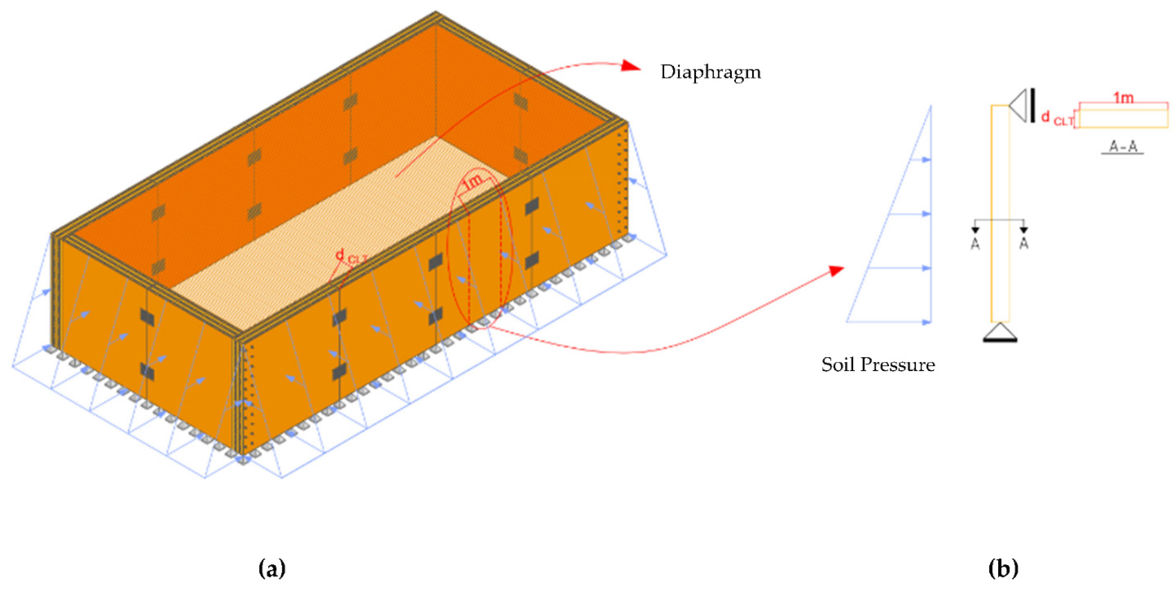
| Architype size | 6 m × 12 m × 3 m | 12 m × 12 m × 3 m | 6 m × 12 m × 3 m | 1 m × 3 m |
| Panel-to-panel connections | Excluded | Excluded | Included | Excluded |
| Layer Name | Distance | Thickness (mm) | Type | Material | Material Angle |
|---|---|---|---|---|---|
| 1 | 0 | 35 | Shell | CLT—longitudinal | 0 |
| 2 | 35 | 35 | Shell | CLT—transverse | 90 |
| 3 | 70 | 35 | Shell | CLT—longitudinal | 0 |
| 4 | 105 | 35 | Shell | CLT—transverse | 90 |
| 5 | 140 | 35 | Shell | CLT—longitudinal | 0 |
| No. Plies | Model Label | Model A | Model B | Model C | Model S (Simplified) |
|---|---|---|---|---|---|
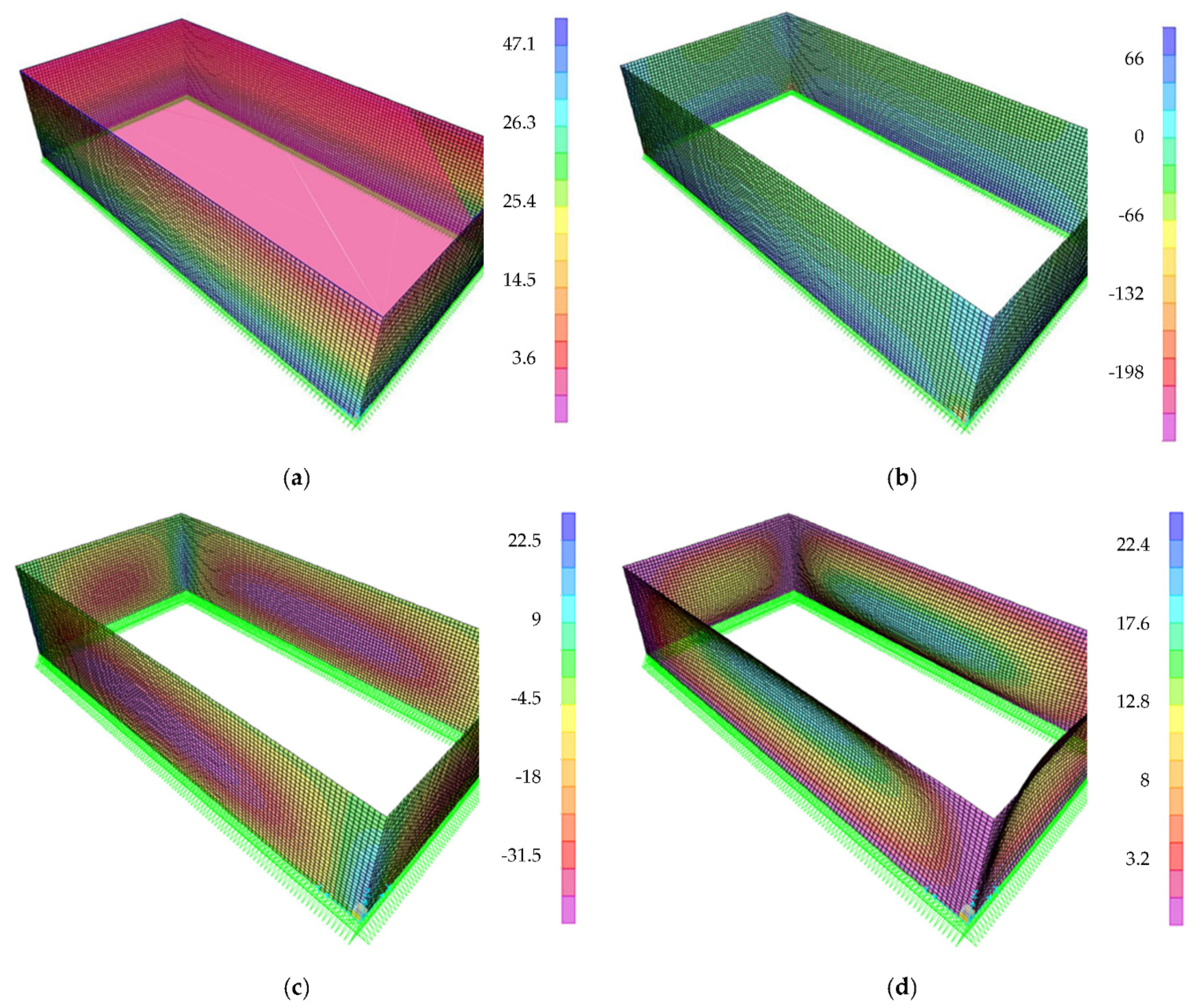
| 3-Ply CLT | Maximum moment—factored (kN·m/m) | 40 | 40 | 42 | 41 1 |
| Location of maximum moment | Middle of longer walls—middle height | Middle of walls | Middle of longer walls—middle panels—middle height | 1.268 from the bottom of the wall 2 | |
| Maximum shear—factored (kN/m) | 68 | 68 | 71 3 | 71 4 | |
| Location of maximum shear | Bottom of walls | Bottom of walls | Bottom of longer walls—middle panels | Bottom of walls | |
| Maximum deflection—unfactored (mm) | 20 | 20 | 22 | 24 5 | |
| Location of maximum deflection | Middle of longer walls—middle height | Middle of walls | Middle of longer walls—middle panels—middle height | Approximately middle height | |
| 5-Ply CLT | Maximum moment—factored (kN·m/m) | Similar to 3-ply CLT | |||
| Location of maximum moment | |||||
| Maximum shear—factored (kN/m) | |||||
| Location of maximum shear | |||||
| Maximum deflection—unfactored (mm) | 4 | 4 | 5 | 6 | |
| Location of maximum deflection | Middle of longer walls—middle height | Middle of walls | Middle of longer walls—middle panels—middle height | Approximately middle height | |
| 7-Ply CLT | Maximum moment—factored (kN·m/m) | Similar to 3-ply and 5-ply CLT | |||
| Location of maximum moment | |||||
| Maximum shear—factored (kN/m) | |||||
| Location of maximum shear | |||||
| Maximum deflection—unfactored (mm) | 2 | 2 | 2 | 3 | |
| Location of maximum deflection | Middle of longer walls—middle height | Middle of walls | Middle of longer walls—middle panels—middle height | Approximately middle height | |
Publisher’s Note: MDPI stays neutral with regard to jurisdictional claims in published maps and institutional affiliations. |
© 2022 by the authors. Licensee MDPI, Basel, Switzerland. This article is an open access article distributed under the terms and conditions of the Creative Commons Attribution (CC BY) license (https://creativecommons.org/licenses/by/4.0/).
Share and Cite
Daneshvar, H.; Fakhrzarei, M.; Imamura, F.; Chen, Y.; Deng, L.; Chui, Y.H. Structural Analysis and Design of Sustainable Cross-Laminated Timber Foundation Walls. Buildings 2022, 12, 979. https://doi.org/10.3390/buildings12070979
Daneshvar H, Fakhrzarei M, Imamura F, Chen Y, Deng L, Chui YH. Structural Analysis and Design of Sustainable Cross-Laminated Timber Foundation Walls. Buildings. 2022; 12(7):979. https://doi.org/10.3390/buildings12070979
Chicago/Turabian StyleDaneshvar, Hossein, Mahboobeh Fakhrzarei, Fernanda Imamura, Yuxiang Chen, Lijun Deng, and Ying Hei Chui. 2022. "Structural Analysis and Design of Sustainable Cross-Laminated Timber Foundation Walls" Buildings 12, no. 7: 979. https://doi.org/10.3390/buildings12070979
APA StyleDaneshvar, H., Fakhrzarei, M., Imamura, F., Chen, Y., Deng, L., & Chui, Y. H. (2022). Structural Analysis and Design of Sustainable Cross-Laminated Timber Foundation Walls. Buildings, 12(7), 979. https://doi.org/10.3390/buildings12070979