Article

The Modification of the Estimated Seismic Behaviour of R/C Low-Rise Buildings Due to SSI

by
Paraskevi K. Askouni
* and
Dimitris L. Karabalis
Department of Civil Engineering, University of Patras, 26504 Patras, Greece
*
Author to whom correspondence should be addressed.
Buildings 2022, 12(7), 975; https://doi.org/10.3390/buildings12070975
Submission received: 3 June 2022 / Revised: 30 June 2022 / Accepted: 4 July 2022 / Published: 8 July 2022
(This article belongs to the Section Building Structures)

Abstract

:
A numerical investigation of the seismic behaviour of asymmetrical low-rise reinforced concrete (R/C) frames is performed considering the deformability of the supporting soil. The typical rigid base assumption is adopted by most current seismic design codes for ordinary buildings, implicitly assuming that the “beneficial” influence of the Soil-Structure Interaction (SSI) effects results in a decrease of the internal forces of a structure. However, in recent research works, SSI is found to affect the structural response in not always a beneficial manner and occasionally in a detrimental one. In the current study, the non-linear time-domain seismic analyses of selected 2D and 3D symmetric and asymmetric R/C framed buildings are presented considering initially the fixed base assumption. Subsequently, these R/C building models, subjected to the same seismic excitations, are analysed considering SSI, by applying a set of orthogonal footings with tie beams which interact with the soil medium. In addition, in the 3D models, the case of a foundation mat supporting the frames is examined. Comparisons between the numerical response results obtained for the examined supporting conditions yield useful conclusions regarding the modified elastoplastic estimated behaviour of common low-rise R/C buildings due to SSI, which can be used for the improvement of the seismic design codes.

1. Introduction

In the conventional seismic design, e.g., Eurocode 8 [1], common reinforced concrete (R/C) buildings are considered to be supported on rigid soil. According to these provisions, the soil deformability necessarily needs to be taken into account only for the design of special structures, structures founded on very soft soils, structures with massive or deep-seated foundations, slender tall structures, such as towers, masts and chimneys, or structures where P-Δ effects may be important to the structural response. Additionally, the current seismic code [1] adopts as adequate and conservative the consideration of a rigid soil in the seismic design of usual R/C framed buildings. Moreover, the consideration of the soil deformability in the usual seismic structural design rests on the initiative of the design engineer, to discriminate a possible adverse influence on the seismic response [1], as well as the choice of the appropriate method and engineering tools to confront the latter issue.
However, the dynamic Soil-Structure Interaction (SSI), as compared to the traditional fixed base assumption, has been found to strongly affect the seismic response of structures by increasing the natural period and the participation of the fundamental mode resulting in greater maximum deformations, increased ductility structural demand and large residual displacements [2,3,4,5]. Furthermore, SSI can cause unfavourable seismic behaviour of R/C common structures by (a) increasing internal forces and base shear [6,7,8,9] and (b) modifying the modal shapes of R/C framed buildings, particularly those supported on softer soils, and, thus, amplifying the vertical component of the seismic response [10].
In view of the vast number of articles available for SSI, in the following, a brief, but indicative, literature review is attempted besides the more general references [2,3,4,5] mentioned previously. Oz et al. [11] reported on an increase in interstorey drift seismic demands in the first stories of multi-storey R/C buildings when SSI is considered, as compared to fixed base boundary conditions. Tomeo et al. [12] investigated moment-resisting R/C frames by using non-linear dynamic analyses for various earthquake excitations, concluding that SSI may lead to a reduction of the estimation of seismic demands while pointing to a wide dispersion of numerical results for various SSI modelling approaches and the significance of SSI effect only for very soft soils [12]. Arapakou and Papadopoulos [13] performed parametric analyses of R/C structures with grid strip footings on a flexible soil and reported that SSI leads to a redistribution of the bending moments in the superstructure and foundation. A synthesis of the scientific knowledge on SSI is presented in [14], where SSI simulation techniques are described, some multistorey buildings are analysed and general recommendations for modelling SSI effects on buildings are provided. Summarising the aforementioned indicative research, SSI has been identified to affect the seismic response of special structures in view of global response parameters, e.g., the lateral roof displacement, interstorey drift and the storey shear [14].
The typical fixed base assumption, usually via simplified analytic or semi-analytic approaches, is commonly considered in the various investigations examining the effect of asymmetry on structural response. Rutenberg et al. [15] used approximate analytical formulations for the evaluation of the modal characteristics of asymmetric wall-frame structures. In a series of publications, De La Llera and Chopra [16,17,18,19] studied asymmetric buildings using simplified models and analytical formulations and presented the seismic response of macroscopic structural quantities. Bosco et al. [20,21] developed a simple method for the evaluation of the in-plan irregularity of asymmetric buildings and presented numerical results of a case study. In addition, Bosco et al. [22] performed a comparison study regarding available non-linear static analysis methods for the assessment of the seismic response of asymmetric buildings. Jiang and Kuang [23] evaluated the inelastic seismic response of two-way asymmetrical multi-storey R/C buildings by using an analytical method and illustrated the coupling of the lateral-torsional components of the structural response. A fast assessment method for determining the drift demand in multi-storey asymmetrical buildings has been presented by Khatiwada et al. [24]. Interesting reviews on the seismic behaviour of asymmetrical structures can be found in Refs [25,26,27,28].
Pilarska and Maleska [29] performed seismic time-history analyses of two steel geodesic domes omitting the SSI effect, since this was not necessary for these case domes according to the provisions of Eurocode 8 [1]. Fan et al. [30] investigated the applicability of the provisions of the current seismic codes for the non-structural components of single-layer spherical reticulated shells considering a direct fixed connection of the boundary shell nodes to the ground, i.e., neglecting SSI. Double-layered steel grid-shell domes were analysed by response spectrum seismic analyses by Nair et al. [31], considering the fixed base assumption. Roopa et al. [32] conducted response spectrum seismic analysis of a single layer latticed geodesic steel dome comparing the SSI consideration to the fixed base assumption. Karavasilis et al. [33] investigated the seismic response of spherical steel tanks considering the fluid-structure-soil interaction. SSI was considered by Bhargava et al. [34] in the evaluation of the seismic fragility of an elevated water-retaining structure, consisting of a hollow circular base raft, the hollow supporting concrete tower, the spherical tank and the central cylindrical access shaft. The importance of the SSI effects on the seismic response was underlined by Talaslidis et al. [35] in the transient analysis by the finite element method (FEM) of a steel storage tank with a circular in-plan shape. An examination of the role of SSI was performed by Kumar et al. [36] by the seismic time-history analysis of a nuclear containment structure with a dome at its top. Summarising the latter research works, among the various works available in the worldwide literature, occasionally the consideration of SSI turns to affect the seismic response of domes, or structures including a dome at the top, or structures with a circular in-plan shape, while, on the other hand, sometimes, the role of SSI may be neglected as not necessarily required in these case structures [1].
Moreover, the influence of the earthquake incidence angle on the structural response is investigated in various research works for the typical fixed base assumption, where global response parameters are used for the evaluation of the response results [37,38,39,40,41,42]. In the later works, investigations are performed on the critical angle of seismic incidence concerning the most detrimental structural response.
In the current investigation, an attempt is made to demonstrate the modification of the estimated seismic behaviour of usual low-rise R/C frames in detail, in 2D and 3D conditions, due to the deformability of the supporting soil, as compared to the fixed base assumption. The non-linear behaviour of R/C sections is taken into account in the current non-linear time-history analyses (NLTH), which provide more accurate results than other types of analysis, although they are more computationally intensive [22], since, among other reasons, a significant number of accelerograms is necessary [1].
The aim of this work is to study the effects of SSI on the most common R/C buildings, i.e., low-rise framed structures with asymmetries in the spatial distribution of cross-sections and stiffnesses of vertical members, as they are often met in common engineering practice. This asymmetry is expressed in terms of dimensionless parameters similar to Refs [7,8,9]. Seismic response results of NLTH analyses, including SSI, are obtained for 2D and 3D R/C frames and are compared to those obtained for the same frames supported on a fixed base. The evaluation of the non-linear response results is performed on the basis of global response parameters and a detailed investigation of the redistribution of the internal forces of R/C elements due to SSI, while using the dimensionless parameters for the relative asymmetry of vertical R/C elements.

2. Description of R/C Structures and Methodology

As a first step, ordinary 2D R/C building frames are investigated by NLTH analyses under ground motion to identify the role of SSI on their seismic behaviour. The non-linear response results of the dynamic analyses of the 2D R/C frames considering the ground deformability are compared to the respective ones obtained for the typical fixed base assumption, which serves as a reference point. Then, a group of simple one- and three-storey 3D building frames are examined by NLTH analyses to observe the SSI effect on the 3D structural response.

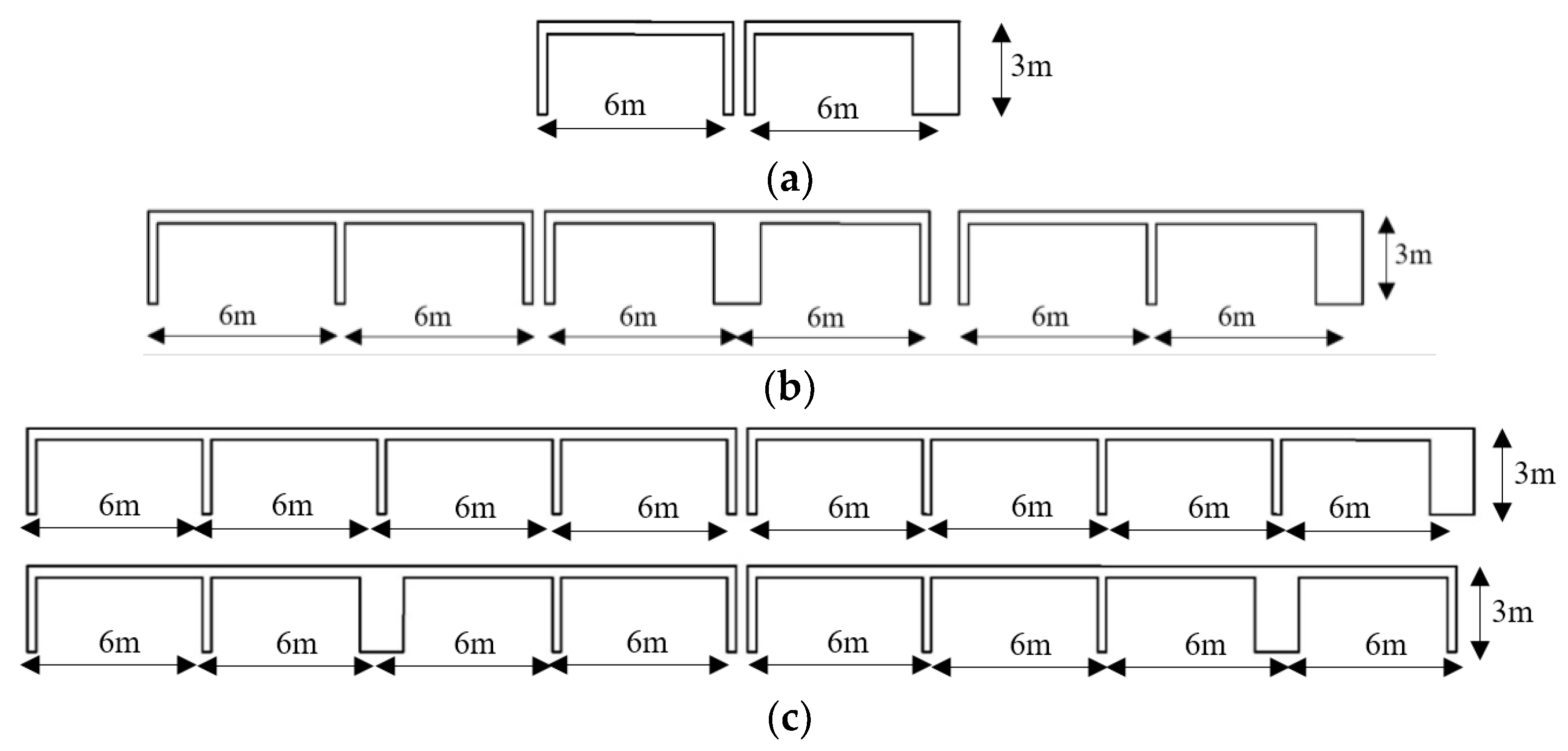
2.1. One-Storey 2D R/C Frames

The one-storey 2D R/C building frames with one, two and four equal spans of 6.0 m, shown in Figure 1a–c, and a height of 3.0 m are considered, for reasons of simplicity, as corresponding to common R/C buildings. Initially, all the vertical elements have the same cross-section of 0.40 × 0.40 m2, while the horizontal R/C beams have a constant cross-section of 0.25 × 0.50 m2. Subsequently, a simple structural asymmetry is introduced by increasing the cross-section of only one vertical element, as shown in Figure 1a–c, referred to as “wall”, in small incremental steps from 0.40 × 0.40 m2 to 0.30 × 2.00 m2. The material used for all 2D R/C elements is concrete C20/25 with steel reinforcement B500c. A uniform load of 34 kN/m is applied upon the R/C horizontal beam, which accounts for the entire dead and live load of typical R/C buildings with domestic/residential and office use as well as the self-weight of perimetric masonry walls [43]. The contribution of the masonry wall infills to the frame stiffness is neglected [44,45], since the present study focuses on the effect of the relative asymmetry of the vertical R/C elements on the structural seismic response.
The 2D R/C frames are dimensioned as ordinary buildings (importance factor γI = 1.0) according to the seismic provisions of the relevant Eurocodes [1,46] for a ductility class medium (DCM), including capacity design of joints and R/C elements in shear, and assumed to stand on a rigid soil of a site with zone ground acceleration ag = 0.36 g. The design assumptions, according to the seismic code [1], are design spectrum of type 1, viscous damping ratio of 5%, soil type C and behaviour factor estimated for each building frame by [1]. The foundation of the 2D frames is designed as orthogonal R/C footings interconnected with R/C tie beams and dimensioned according to the current codes [1,47].
For the purposes of this work, a suitable elastoplastic mechanical model [48,49,50] is chosen for the simulation of the elastoplastic behaviour of R/C sections under strong loading. Thus, elastoplastic point hinges are applied at both ends of all R/C elements accounting for all material and sectional features, such as dimensions, steel reinforcement, reduced stiffness, elastoplastic mechanical limits of strength, deformation/curvature, etc. [48,49,50]. The simplification of the elastoplastic behaviour of R/C sections by the application of elastoplastic point hinges at the ends of R/C elements is convenient and widely used for the non-linear dynamic analysis of whole framed R/C structures [51,52]. The employed elastoplastic mechanical model [48,49,50] provides complete information on the failure quantities for the R/C sections, such as the yielding and ultimate bending moments, the yielding, ultimate and plastic curvature and the yielding, ultimate and plastic chord rotation angles, as well as the ductility demand calculated in terms of the chord rotation at the R/C cross-section [1,51,52].
In the available literature, a vast variety of SSI models can be found, e.g., Refs [53,54,55,56,57], from the simplest to the most complicated ones. However, this study aims at demonstrating the important role of SSI in the seismic analysis and design of common low-rise R/C buildings. To this end, the interest of this numerical investigation is focused on the modification of the seismic behaviour of R/C buildings due to SSI, as compared to the fixed base assumption, in combination with the simple aforementioned geometrical asymmetry, avoiding the unnecessary complexity introduced by the numerous parameters of the SSI formulations [4,5] and neglecting possible non-linear soil behaviour, such as soil liquefaction, ground subsidence and foundation uplift [58,59,60,61]. Therefore, the SSI model selected here makes use of discrete elements comprised of a simple spring-dashpot-mass system. This system is applied at the basis of each vertical element, whereas its numerical values are calculated according to [62]. For this study, the soil properties are assumed as Poisson ratio νs = 0.4, soil density ρs = 1750 kgr/m3, modulus of elasticity Es = 150 MPa and shear velocity Vs = 175 m/sec, corresponding to a medium clay.
The non-linear time history (NLTH) analyses are performed for an artificial accelerogram compatible with the design spectrum [1], constructed by ETABS [63] based on the earthquake of Argostoli (Kefalonia, Greece) of 2014 [64], with a moment magnitude Mw = 6.0, epicentre 38.25 N, 20.39 E and depth 10.0 km. The NLTH analyses of all 2D R/C frames are accomplished by ETABS [63], first under the assumption of a rigid base and then with the inclusion of SSI.

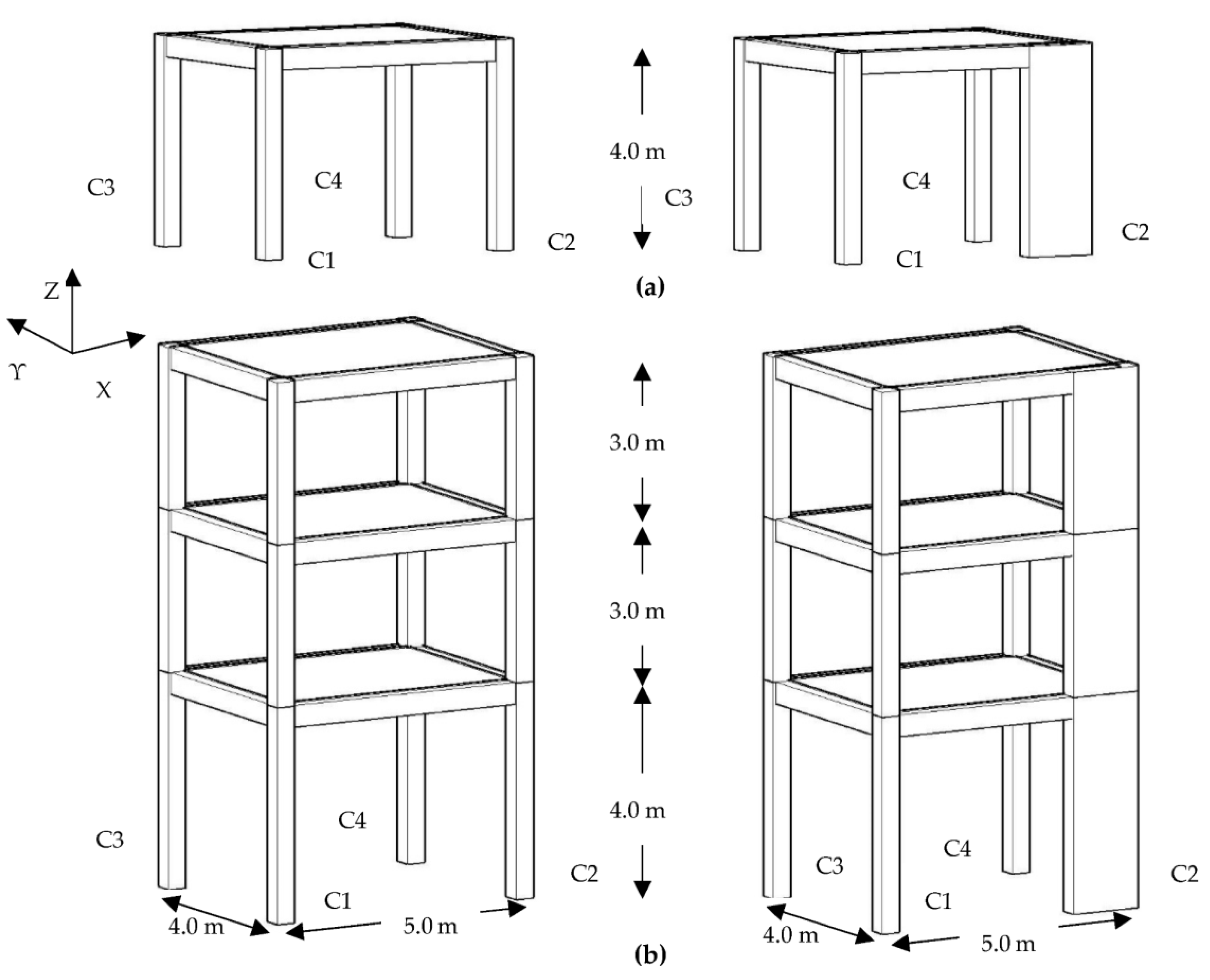
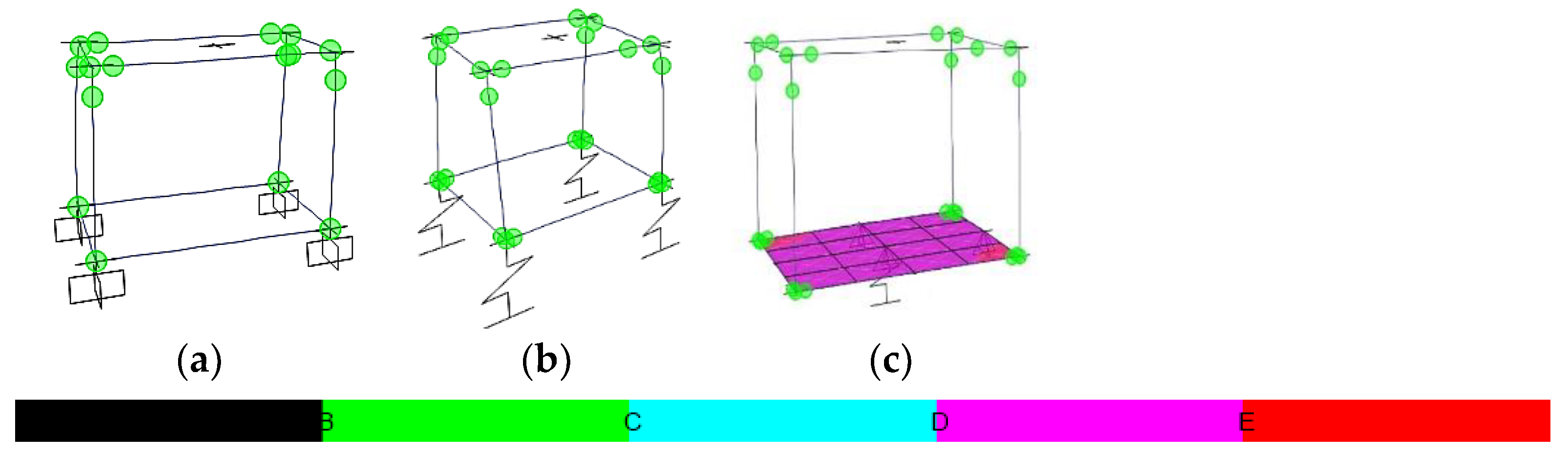
2.2. One- and Three-Storey 3D R/C Frames

The one-storey, 4 m height, 3D R/C building frames shown in Figure 2a are typical of small, low-rise common R/C buildings which consist of a 5.0×4.0 m2 slab supported by perimetric beams and four columns at the corners, similar to a design model analysed in Ref. [65]. By adding two more similar-in-plan stories with a height of 3.0 m, over the described one-storey 3D building, the three-storey 3D building is formed as shown in Figure 2b [65]. A simple geometrical in-plan asymmetry is introduced by increasing the cross-section of only one column, i.e., C2, which in the following is referred to as “wall”, in small consecutive steps from 0.40 × 0.40 m2 on the 1st storey, or 0.35 × 0.35 m2 on the 2nd and 3rd stories, up to 0.30 × 2.00 m2. The remaining columns, i.e., C1, C3 and C4, are kept at a constant cross-section of 0.40 × 0.40 m2 on the 1st storey or 0.35 × 0.35 m2 on the 2nd and 3rd stories. The horizontal R/C beams have a constant cross-section of 0.25 × 0.60 m2 at all stories. Diaphragm action is assumed for each floor due to the presence of R/C slabs with a thickness of 0.15 m. The global coordinate system is shown in Figure 2.
The material of the 3D frames is C20/25 with steel reinforcement B500c. The one- and three-storey R/C frames are designed as ordinary buildings (the importance factor is 1.0) according to the provisions of relevant Eurocodes [1,46]. The load on the floors consists of a 2 kN/m2 dead load and 0.6 kN/m2 live load [43]. The weight of a perimeter wall is considered through the application of a dead load of 12.24 kN/m on the R/C beams on the 1st storey and 8.64 kN/m on the 2nd and 3rd stories, and a wall parapet of 1 m height is considered over the 3rd storey with a dead load of 3.6 kN/m. The 3D R/C buildings are seismically designed for DCM including capacity design of joints and R/C elements in shear, for the typical rigid base assumption [1] (Figure 3a). The dimensioning assumptions, following the provisions of the current seismic code [1], are zone ground acceleration ag = 0.36 g, type 1 of the design spectrum, viscous damping ratio 5%, soil type C and behaviour factor estimated for each 3D building frame by [1]. The design seismic loading is considered for both horizontal global directions following the 30% combination rule and considering an accidental eccentricity of 5% [1].
The foundation of the 3D buildings is designed in two ways. At first, a system of orthogonal R/C footings, at the base of vertical elements, interconnected with R/C beams is designed to support each 3D building. Next, an R/C foundation mat with internal beams interconnecting the bases of vertical elements is designed for each 3D building frame. Both foundation types are designed and dimensioned according to the provisions of the current codes [1,46,47].
Similarly, to the previous Section 2.1, the SSI effect is considered by the application of a spring-dashpot-mass system at the basis of each vertical element, for the case of a foundation consisting of footings with tie beams (Figure 3b), calculated as in [62]. For the foundation mat case, considered rigid for all practical purposes, a spring-dashpot-mass discrete system is applied at the geometrical centre of the foundation mat (Figure 3c) to represent a deformable soil [62]. For the current analyses, the soil properties are considered as follows: Poisson ratio νs = 0.4, soil density ρs = 1600 kgr/m3, modulus of elasticity Es = 150 MPa and shear velocity Vs = 183 m/sec, corresponding to a medium clay, type C ground.
The elastoplastic behaviour of R/C sections is considered by the same (as in Section 2.1) elastoplastic mechanical model [48,49,50], by the application of elastoplastic point hinges at both ends of all R/C elements [51,52]. The NLTH analyses of the 3D buildings are performed employing the three components, i.e., two horizontal and one vertical, of the accelerograms recorded by the earthquakes of (i) Vasiliki (Lefkada, Greece) on 17 November 2015, with moment magnitude Mw = 6.4 and peak ground acceleration (PGA) of 3.63 m/sec2 in the north-south direction, 3.27 m/sec2 in the east-west direction and 2.58 m/sec2 in the vertical direction and (ii) Lixouri (Kefalonia, Greece) on 3 February 2014, with Mw = 6.1 and PGA of 5.93 m/sec2 in the north-south direction, 5.03 m/sec2 in the east-west direction and 5.03 m/sec2 in the vertical direction. More information on the location, soil type, proximity to the fault, etc., for these strong ground motions can be found in [64]. Furthermore, the acceleration spectrum of the Vasiliki earthquake is found in [9] to be relatively close to the design spectrum [1], and thus, is considered appropriate for the current NLTH analyses. The Lixouri earthquake is chosen for the present NLTH analyses, as an example of strong seismic motion with an acceleration spectrum much greater [9] than the design spectrum [1]. It should be noted that the current work investigates the effect of SSI combined with the simple relative asymmetry of the vertical R/C elements of various low-rise framed R/C buildings on the seismic structural response. It is not indented to provide a detailed study on the seismic design and analysis of R/C buildings, which is the subject of an entirely different area of research [51,52].
From the available literature, e.g., Refs [37,38,39,40,41,42], it is clear that the incidence angle “φ” of the seismic motion has a serious effect on the response of a structure. In the current study, based on the geometry of the described 3D building frames, the selected earthquake incidence angles are φ = 0° and φ = 90°, i.e., along the two primary geometrical axes, and φ = 45°, close to the geometrical diagonal axis, as shown in Figure 4.
The 3D NLTH analyses of the 3D building frames are performed by ETABS [63] at first for the typical rigid soil assumption, then by considering SSI with individual footings interconnected with tie beams, and a foundation mat. All the 3D NLTH analyses are performed for the aforementioned earthquakes for the three selected incidence angles. The seismic response results are evaluated through global, as well as detailed (local) parameters, i.e., at the level of each R/C element and storey.

3. Numerical Results and Discussion

In this section, the seismic response results of the R/C 2D and 3D building frames of Figure 1 and Figure 2, when subjected to the described ground motions of Section 2, are presented and discussed. The current NLTH analyses aim to investigate the modification of the seismic response parameters due to SSI in 2D and 3D conditions, considering the simple geometrical asymmetry of the cross-section and stiffness of the R/C vertical elements, which is numerically expressed by the following ratios: “I(wall)/I(col)” is the ratio of the moment of inertia of the wall to column vertical element and similarly “A(wall)/A(col)” referring to the cross-sections and “J(wall)/J(col)” referring the polar moment of inertia of R/C elements. In the following plots, the ratios I(wall)/I(col) and A(wall)/A(col) are depicted at the horizontal axis, which means that the value of I(wall)/I(col) and A(wall)/A(col) equal to one refers to the symmetric building with equal cross-sections of the vertical elements.
More specifically, there are presented plots of the maximum interstorey drift ratio, IDR, with the notations “r.s.” for rigid soil, “s” for SSI considering a foundation consisting of footings interconnected with tie beams or “m” for SSI considering foundation mat, on both horizontal directions, X and Y, along with the ratio A(wall)/A(col). The maximum IDR values of the current analyses are graphically compared to the limit IDR values for the seismic performance levels [66], as mentioned here for convenience, IO (Immediate Occupancy), LS (Life Safety) and CP (Collapse Prevention), which read 1%, 2% and 4%, respectively, for R/C frames.
Dimensionless plots of internal forces of R/C vertical elements are shown as follows. The ratio of the maximum absolute value of the internal bending moment of a vertical element for SSI consideration by footings with tie beams, to the respective value, at the same location, for the rigid soil assumption, is called here “M(s)/M”. Considering the foundation mat, in addition to the case of the 3D buildings, a similar ratio is “M(m)/M”. These ratios, M(s)/M and M(m)/M, are plotted at the lower section “bot” and the upper section “up” of each vertical element at each storey and shown here only for their major internal axis, to save space. Interest is raised in the behaviour of the vertical R/C elements, which are the major ones, as usual in the seismic design and analysis of R/C building frames [1,51,52].
Similarly, the ratio of the internal shear forces is defined as “V(s)/V” for the case of footings and “V(m)/V” for the case of foundation mat to rigid soil assumption. These ratios of internal shear forces are presented here only for the major internal axis, due to space limitations. Respectively, the ratio of internal torque of vertical R/C elements (around the longitudinal axis of each element) is defined as “T(s)/T” for footings with tie beams and “T(m)/T” for foundation mat to the rigid soil.
Similarly, the maximum absolute value of the storey moment is examined at both X and Y global axes (Figure 2) by the use of the dimensionless ratio “Mb(s)/Mb” or “Mb(m)/Mb” for footings or foundation mat to rigid soil, respectively, examined at both global horizontal axes. Consequently, the ratios “Vb(s)/Vb” and “Vb(m)/Vb” refer to the storey shear considering SSI via footings with tie beams, or foundation mat to rigid soil. Finally, the ratios “Tb(s)/Tb” or “Tb(m)/Tb” refer to the storey torque, around the Z global axis (Figure 2).
In some selected plots, a dashed black vertical line is added, labelled as “wall”, referring to the limit of the geometrical wall definition [1,46]. Additionally, a blue solid vertical line, labelled as “K(wall) > 3K(beam)”, indicates the limit of the wall stiffness being greater than three times the beam stiffness, which is the qualitative limit of characterising a vertical R/C element as “wall”. The behaviour of the elastoplastic hinges at the element ends is presented in selected plots, with notation for each R/C section of the following limits: “A” refers to elastic behaviour, “B” refers to yielding bending moment limit [1,46,67], “C” refers to ultimate bending moment limit [1,46,67], “D” refers to residual bending moment limit [1,46,67] and “E” refers to values of bending moments greater than the maximum moments and deformations greater than the ultimate deformation [1,46,67]. All the necessary limits of bending moment, chord rotation and deformation have been already calculated by the aforementioned elastoplastic model for each end of R/C elements and induced in the analysis model by ETABS [63].
The use of dimensionless parameters to evaluate the analysis results serves better to provide more general and objective remarks. Due to space limitations, only the most characteristic response plots are presented here.

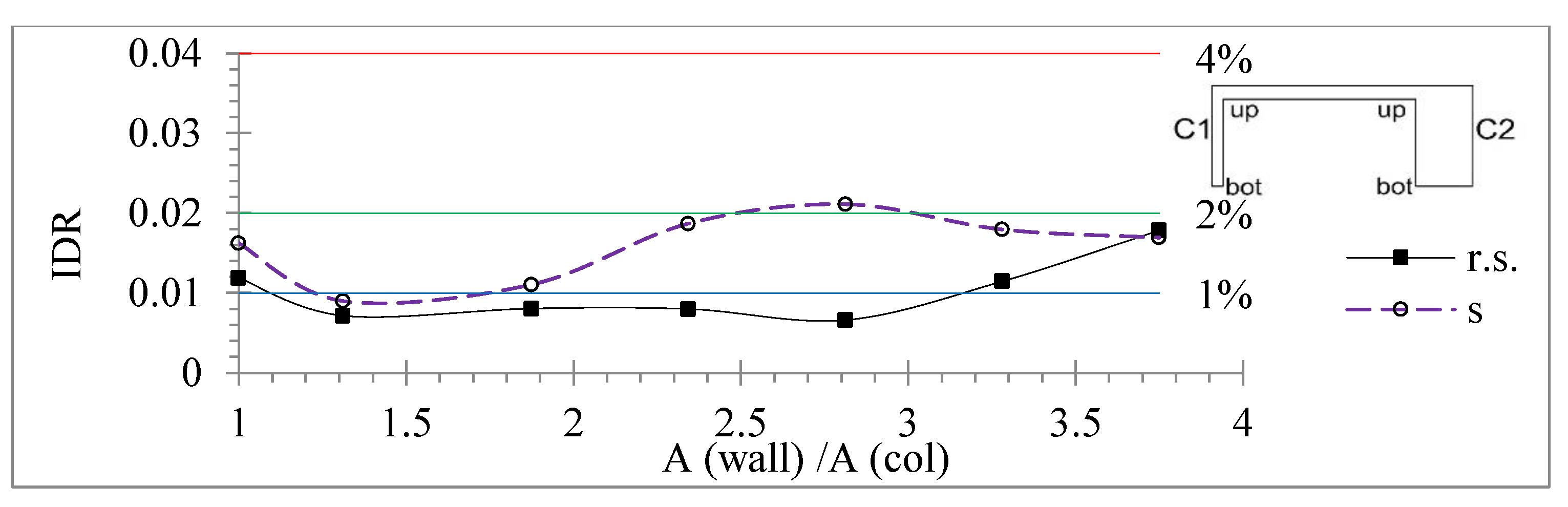
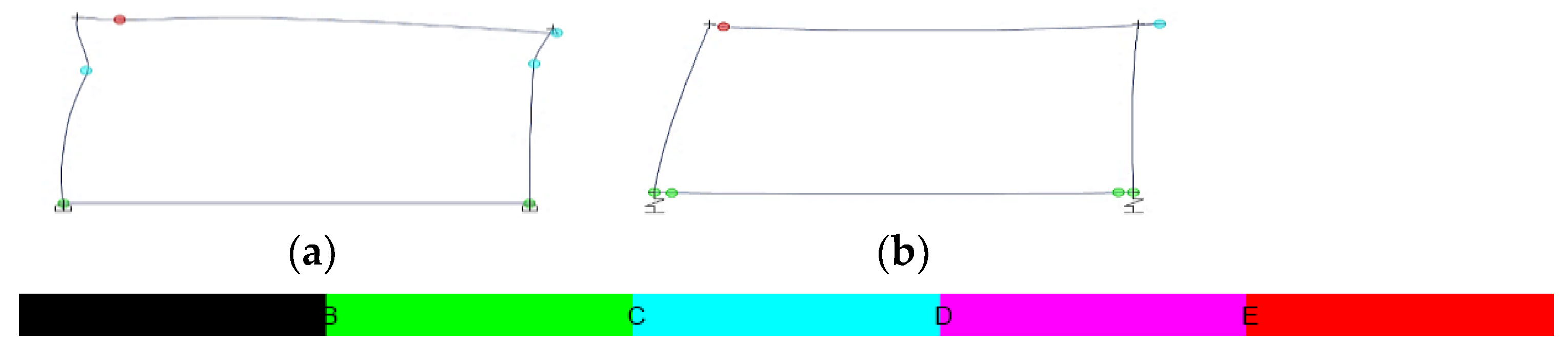
3.1. One-Storey 2D R/C Building Frames

Starting from the one-storey 2D R/C frames with one span, the IDR has greater values for SSI than rigid soil for almost all wall sections (Figure 5). The IDR for SSI remains almost below the limit of 2% for all sections except for A(wall)/A(col) = 2.81, where it exceeds slightly the limit of 2% while staying constantly within the limit of 4% (Figure 5). The formation of elastoplastic hinges is similar for both supporting conditions, as shown in Figure 6.
At the one-storey 2D R/C frames with two spans by altering the middle R/C vertical element, the M(s)/M at the bottom of vertical elements varies, tending to decrease along with the increase of the I(wall)/I(col) to 0.96 for C1, 0.63 for C2 and 0.58 for C3 (Figure 7a). The M(s)/M for the top section of C1 tends to variably increase along with the increase of the wall section up to 2.92 for I(wall)/I(col) = 39.55 and decreases down to 0.96 for I(wall)/I(col) = 93.75. As shown in Figure 7a, the M(s)/M for the top section of C2 and C3 increases up to 2.06 and 3.08, respectively, for the limit of the “wall” section and decreases to 0.76 and 0.54, respectively, for the largest wall section.
As observed in Figure 7b, the V(s)/V ratio of C1 and C3 varies, tending to increase along with the increase of the wall section up to 1.48 and 0.43 for A(wall)/A(col) ≤ 2.81, and decreases for greater wall sections down to 0.91 and 0.55, respectively, for the greatest wall section. The wall section benefits from SSI by the decreasing V(s)/V ratio along with its increase down to 0.69 for the greatest wall section (Figure 7b). A small influence of SSI on the redistribution of internal bending moment and shear forces is observed in the case of the symmetrical frame (Figure 7a,b).
At the two-spanned 2D one-storey frames, as indicatively shown in Figure 8, the formation of elastoplastic hinges tends to be quite similar for SSI and rigid soil. The SSI tends to relieve the hinges at the top section of vertical elements, as compared to the rigid soil in Figure 8.
At the 2D one-storey frames with two spans by altering the extreme column, C3, as shown in Figure 9, the IDR for SSI variably increases along with the increase of A(wall)/A(col) even with values greater than the limit of 4%, i.e., up to 4.1% for A(wall)/A(col) = 1.875 and 5.4% for A(wall)/A(col) = 3.28. The IDR for rigid soil varies in the range of 1.2~3.4% for all wall sections, within the limit of 4%. The behaviour of elastoplastic hinges tends to be overwhelmed, moving to a worse performance level [1] for SSI, compared to rigid soil, as shown in Figure 10, specifically more at the basis of the vertical R/C elements.
Next, at the 2D one-storey frames with four spans by altering the middle vertical element, as shown in Figure 11, the IDR for rigid soil variably increases up to 4.4%, i.e., over the 4% limit, for the “wall” cross-section limit and decreases variably along with the increase of A(wall)/A(col) to 3.4% for the greatest wall section. The IDR for SSI variably increases up to 3.9% for the wall cross-section limit and decreases to 2% for the greatest wall section. For the symmetric frame, i.e., A(wall)/A(col) = 1, the IDR has very close values for both SSI and rigid soil, as in Figure 11. As observed in Figure 12, SSI tends to stress more the elastoplastic hinges at the base of vertical elements, as well as the hinges at the ends of the foundation tie beams, as compared to the rigid soil.
At the 2D one-storey frames with four spans by altering the 4th vertical element, as shown in Figure 13, the IDR for rigid soil varies in the range of 1.6~3.2% and for SSI varies in a smaller range of 1.3~2.5%. At the symmetric frame with four spans, very close values of IDR are observed for both SSI and rigid soil for great wall sections, e.g., A(wall)/A(col)≥ 3.28 (Figure 13). As shown in Figure 14, for the four-spanned frame with equal cross-sections of columns, SSI tends to overwhelm the hinges at the tie beams and the top sections of the columns, more than the rigid soil. As identically shown in Figure 15, at the four-spanned frame with the 4th column cross-section as 100/30 cm, SSI stresses the basis of most of the vertical elements, the ends of the tie beams and the top section of the column C5.
Moving to the 2D one-storey frame with four spans by altering the extreme vertical element, as in Figure 16, the M(s)/M of all vertical elements varies along with the increase of the wall section, showing greater values at the top section than the respective bottom section of the vertical elements. The M(s)/M of the top and base section of the wall tends to have smaller values than the respective ratio of the wall (Figure 16). Similarly, the V(s)/V of the wall tends to decrease along with the increase of A(wall)/A(col) down to 0.77 for the greatest wall section (Figure 17). The V(s)/V ratio of C1 and C2 varies, tending to decrease for greater wall sections in the range of 1.37~0.54 (Figure 17). The V(s)/V ratio of C3 and C4 varies, tending to increase even up to 2.35 and 2.33, respectively. The closer columns to the wall, which are C3 and C4, are harmed more by SSI than the more remote columns from the wall, which are C1 and C2, in terms of the M(s)/M and V(s)/V ratios (Figure 16 and Figure 17).
As shown in Figure 16 and Figure 17, for the symmetric frame with four spans with equal cross-sections of vertical elements, the SSI influence on the M(s)/M and V(s)/V ratios tends to be small for the columns C2, C3 and C4, and greater for the wall, C5 and the column C1, which is the most remote from the wall. As indicatively shown in Figure 18, at the 2D frame with four spans by altering the extreme vertical element with wall section 100/30 cm, the elastoplastic hinges of the basis of the R/C vertical elements are stressed more from the rigid soil, while the hinges at the tie beams and the top sections of the R/C vertical elements are stressed more from SSI than the rigid soil assumption.
In addition, after the performance of all NLTH analyses, all the elastoplastic hinges are checked for a possible shear failure according to the provisions of [67] and found not to overpass the shear limit of each R/C section conforming to the guidelines of the current design codes [1,46]. This means that the R/C elements of the investigated frames are successfully designed [1,46] to avoid shear failure at both supporting conditions.

3.2. One-Storey 3D R/C Framed Buildings

At the one-storey 3D R/C frames, as shown in Figure 18, a small and rather beneficial influence of SSI is obvious for the symmetric case, regarding the M(s)/M plot for the Vasiliki earthquake φ = 45°. However, for greater wall sections (Figure 18), the M(s)/M variably increases along with the increase of I(wall)/I(col) with maximum values up to 1.99 for the wall top section, 1.29 for the wall bottom section and 1.68~1.70 for the top and bottom section of C1, respectively. The M(s)/M of top and bottom sections of C3 and C4 varies in the range of 0.90~1.15 with decreasing tendency for greater wall sections (Figure 18).
The torsion ratio of all vertical R/C elements varies, tending to decrease for smaller wall sections, i.e., J(wall)/J(col) ≤ 20, while for greater wall sections, it tends to increase up to 1.12~1.21, as shown in Figure 19a,b. A strong influence of SSI is observed for the symmetric building, with a benefitting effect in T(s)/T down to 0.92, as in Figure 20, and a detrimental effect in T(m)/T up to 1.65, as in Figure 19.
As shown in Figure 20, for the Lixouri earthquake and φ = 0°, the V(m)/V ratio of the wall decreases along with the increase of A(wall)/A(col) down to 0.64 for the greatest wall section. However, simultaneously, the V(m)/V of the columns increases along with the increase of A(wall)/A(col) up to 2.06 for C1, 1.43 for C3 and 1.88 for C4 (Figure 20).
As observed in Figure 21a, for the Vasiliki earthquake and φ = 45°, the Vb ratio on the X axis for footings and foundation mat to rigid soil tends to increase variably with overlapping values up to 1.26 and 1.44, respectively, for the greatest wall section. On the Y axis, for the Vasiliki earthquake and φ = 0°, the Vb ratio for footings varies in the range of 1.1~0.85, tending to decrease along with the increase of the wall section (Figure 21b), while the Vb ratio for foundation mat varies with an increasing tendency in a small range of values, i.e., 0.63~0.78.
For the Vasiliki earthquake and φ = 0°, as presented in Figure 22a, on the X axis, the Mb(s)/Mb ratio varies, tending to decrease along with the increase of I(wall)/I(col) in the range of 1.04~0.83, while the Mb(m)/Mb increases variably in the range of 0.9~1.34. Respectively, on the Y axis (Figure 22b), the Mb(s)/M varies in the range of 1~1.1 along with the increase of I(wall)/I(col), while the Mb(m)/Mb tends to increase in the range of 0.96~1.41.
For the Vasiliki earthquake and φ = 90° (Figure 23a) regarding the asymmetrical 3D building frame, the Tb(s)/Tb ratio varies in the range of 0.8~1.26, while the Tb(m)/Tb varies, tending to increase in the range of 1.04~1.16 along with the increase of J(wall)/J(col). For the Lixouri earthquake and φ = 90° (Figure 23b), the Tb(s)/Tb variably increases in the range of 0.8~1.25, while the Tb(m)/T varies, tending to increase in the range of 0.99~1.32. However, for the symmetrical 3D building, local increased values are observed in Figure 23a,b up to 1.5 for the Tb(s)/Tb and up to 2.66 for the Tb(m)/Tb.
For the Lixouri earthquake and φ = 45°, the IDR on the X axis tends to decrease along with the increase of A(wall)/A(col) for footings and the rigid soil assumption with a range of values 2.3~1.2%, where the IDR for the rigid soil has constantly smaller values (Figure 24a). The IDR on the X axis for foundation mat variably decreases in the range of 2.4~1.9%. The IDR on the Y axis for footings and rigid soil slightly increases along with the increase of A(wall)/A(col) in the range of 2.1~2.4% (Figure 24b). The IDR on the Y axis for the foundation mat varies in the range of 2.8~3.1% along with the increase of the wall section (Figure 24b). The IDR on both axes has smaller values for the rigid soil assumption and greater for the foundation mat (Figure 24a,b).
Concerning the behaviour of the elastoplastic hinges, as shown in Figure 25, Figure 26 and Figure 27, all hinges behave within the limits of the regulation provisions [1,46]. The footings and the foundation mat tend to stress more the hinges at the ends of the tie beams than the rigid soil assumption. Furthermore, the foundation mat tends to stress more the hinges on the top section of the vertical elements than the other supporting conditions. For all the NLTH analyses, the shear limit value [67] was not exceeded in any elastoplastic hinges of the R/C members, conforming to the standards of the current codes [1,46].

3.3. Three-Storey 3D R/C Framed Buildings

On the 1st storey of the three-storey 3D building frames, for the Lixouri earthquake and φ = 90° (Figure 28), the M(m)/M of the wall variably decreases along with the increase of I(wall)/I(col) down to 0.83 for its bottom and 0.71 for its top section. Respectively, the M(m)/M of the columns tends to increase up to 1.37 for the bottom and 1.2 for the top sections of C1, up to 1.34 for the top and 1.13 for the bottom section of C4, and up to 1.06 for the bottom and 1.02 for the top section of C3, all values for the greatest wall section. The greater increase of M(m)/M of the columns is observed for I(wall)/I(col) over the limit of the “wall” section according to the current codes, as plotted in Figure 28.
On the 2nd storey, as in Figure 29, the M(m)/M variably decreases along with the increase of I(wall)/I(col) down to 0.67 for the bottom sections of C1 and C2, to 0.73 for the top of C1 and 0.91 for the top of C2, all values for the greatest wall section. Meanwhile, the M(m)/M variably increases up to 1.43 for the top of C3, 1.24 for the bottom of C4, and close to 1.1 for the bottom of C3 and top of C4 (Figure 29).
On the 3rd storey, as observed in Figure 30, the M(s)/M varies for all vertical elements in the range of 1.25~0.84, tending to greater values for C1 and C4 and smaller values for the wall. Additionally, the top section of vertical elements appears to be stressed more than the respective bottom section by SSI by foundation mat, regarding the M(s)/M.
As observed in Figure 31a,b, for the Lixouri earthquake, on the 1st storey for φ = 45°, the T(s)/T for all vertical elements variably tends to decrease along with the increase of the wall section in the range of 1.73~0.65, tending close to 1.18 for the greatest wall section, while on the 3rd storey for φ = 0°, the T(s)T varies in the range of 1.14~0.97 tending to 1 for the greatest wall section.
On the 1st storey under the Vasiliki earthquake and φ = 45°, the V(m)/V of the wall decreases variably along with the increase of the A(wall)/A(col) in the range of 0.96~0.63 (Figure 32). The V(m)/V of C1 tends to increase up to 1.28 for A(wall)/A(col) = 2.81 and decreases to 0.84 for the greatest wall section. The V(m)/V of C4 varies, tending to increase more intensely over the “wall” limit up to 1.49~1.43. The V(m)/V of C4 increases up to 1.41 for the “wall” limit and decreases for greater wall sections down to 1.13 for the greatest wall section. The “wall” limit appears to be a limit on the behaviour of vertical elements concerning the V(s)/V ratio. The limit of “K(wall) > 3K(beam)” indicates a smaller influence of SSI by values of the V(s)/V closer to 1 (Figure 32).
As shown in Figure 33a, on the 1st storey for φ = 0° under the Lixouri earthquake, the Vb ratio on the X axis has greater values for footings to rigid soil with decreasing tendency in the range of 0.96~1.11, while for foundation mat to rigid soil shows decreasing values in the smaller range of 0.99~0.83. On the 1st storey for φ = 0° under the Vasiliki earthquake (Figure 33b), the Vb ratio on the Y axis has overlapping values for both supporting conditions for A(wall)/A(col) ≤ 2.34 in the range of 0.84~0.97, while for greater wall sections, the Vb ratio on the Y axis increases for the foundation mat, variably tending to 1.14 for the greatest wall section, while for footings the Vb(s)/Vb increases up to 1.28 for A(wall)/A(col) = 2.81 and decreases down to 0.82 for the greatest wall section.
On the 1st storey for φ = 0° under the Vasiliki earthquake, the Mb(s)/Mb on the X axis varies, tending to in the range of 1.33~1.06, while the Mb(s)/Mb varies in the range of 1.21~0.97 (Figure 34a). On the 1st storey for φ = 45° under the Vasiliki earthquake, the Mb(s)/Mb on the Y axis variably increases in the range of 1.17~1.38 along with the increase of I(wall)/I(col), while the Mb(m)/Mb on Y axis fluctuates in the range of 1.08~1.32 (Figure 34b). From Figure 34a,b, the footings to rigid soil case seem to provide a more detrimental effect on the structure than the case of foundation mat, given the Mb(s)/Mb or Mb(m)/Mb ratios.
Under the Lixouri earthquake for φ = 45°, the IDR on the X axis varies in the range of 1~2.6%, tending mostly to smaller values for the rigid soil and greater for the foundation mat (Figure 35a). Similarly, as shown in Figure 35b, the IDR on the Y axis has overlapping values tending to increase for all supporting conditions in the range of 2.7~4.2%, where great values are observed for the rigid soil assumption, even greater than the limit of 4% for A(wall)/A(col) ≥ 2.81.
As observed in Figure 36 for the symmetric 3D three-storey building under the Vasiliki earthquake for various incidence angles, the case of footings (Figure 36b) stresses the elastoplastic hinges at the base of vertical elements and tie beams more than the rigid soil (Figure 36a), while the case of foundation mat (Figure 36c) stresses, even more, the hinges at the base of vertical elements compared to the other supporting conditions.
As observed in Figure 37 for the three-storey building with wall section 125/30 cm under the Lixouri earthquake for various φs, the footings foundation (Figure 37b) stresses more the hinges at the bases and the top section of the vertical elements on the 1st storey and at the tie beams, as compared to rigid soil (Figure 37a). The foundation mat (Figure 37c) similarly stresses the basis of the vertical elements to rigid soil (Figure 37a) and more at the hinges at the tie beams and the top sections of columns of the 1st storey.
At the three-storey building with a wall section 200/30cm under the Lixouri earthquake for φ = 45°, the case of rigid soil stresses more the elastoplastic hinges of the vertical element and the beams of the upper stories (Figure 38a), as compared to the SSI considerations (Figure 38b,c). The foundation mat (Figure 38c) seems to relieve more of the hinges at the vertical elements, as compared to the footings (Figure 38b) and rigid soil assumption (Figure 38a).
The rigid soil case, as defined by the current seismic codes for ordinary buildings, serves as a useful reference point for comparison to SSI, as observed in previous figures. The shear limit of each R/C section [67] was not exceeded at any elastoplastic hinge, as all were checked at the NLTH analyses and expected according to the provisions of the current design codes [1,46].
The investigation of the SSI effects in a few case studies of large multistorey buildings [14] has highlighted the importance of SSI, based on the examination of macroscopic response parameters, and provided general guidelines on the methods and models appropriate for SSI [14]. However, the current study emphasised the role of SSI in the modification of the estimated seismic response of the most common, low-rise R/C framed buildings, by examining macroscopic and other parameters in detail, and thus, leading to practical conclusions for the improvement of the seismic design of such structures.
In addition, as mentioned by the current seismic codes [1,46], the structural asymmetry, even in more complex multistorey 3D R/C frames [21,27], has already been examined in terms of structural eccentricity and torsional radius. The current NLTH analyses, providing more accurate results than other methods [22], of the simple low-rise R/C frames focus on the effect of the relative stiffness asymmetry of the vertical R/C elements, by using the appropriate aforementioned dimensionless ratios.

4. Conclusions

The purpose of this paper is to investigate and discuss the modification of the seismic behaviour of simple low-rise R/C framed buildings due to SSI, in 2D and 3D conditions, considering a simple relative asymmetry of the cross-section and stiffness of vertical R/C members. The elastoplastic behaviour of R/C elements is taken into account in the NLTH analyses through an appropriate elastoplastic model by applying point hinges at both ends of R/C elements. The adopted numerical response results of the examined framed R/C models are limited and based on the aforementioned elastoplastic model of R/C sections. The effect of earthquake incidence angle is considered in the NLTH analyses, while the SSI effect, through two considerations, i.e., the footings with tie beams and the foundation mat, is compared to the usual rigid base assumption. The case of the symmetric building frame is included in the analysis models, too. Dimensionless parameters are preferred for the comparison of the results of the NLTH analyses by ground excitation to provide objective remarks in the current multiparametric investigation. From the current seismic elastoplastic analyses of the selected 2D and 3D building frames, the following conclusions can be drawn.
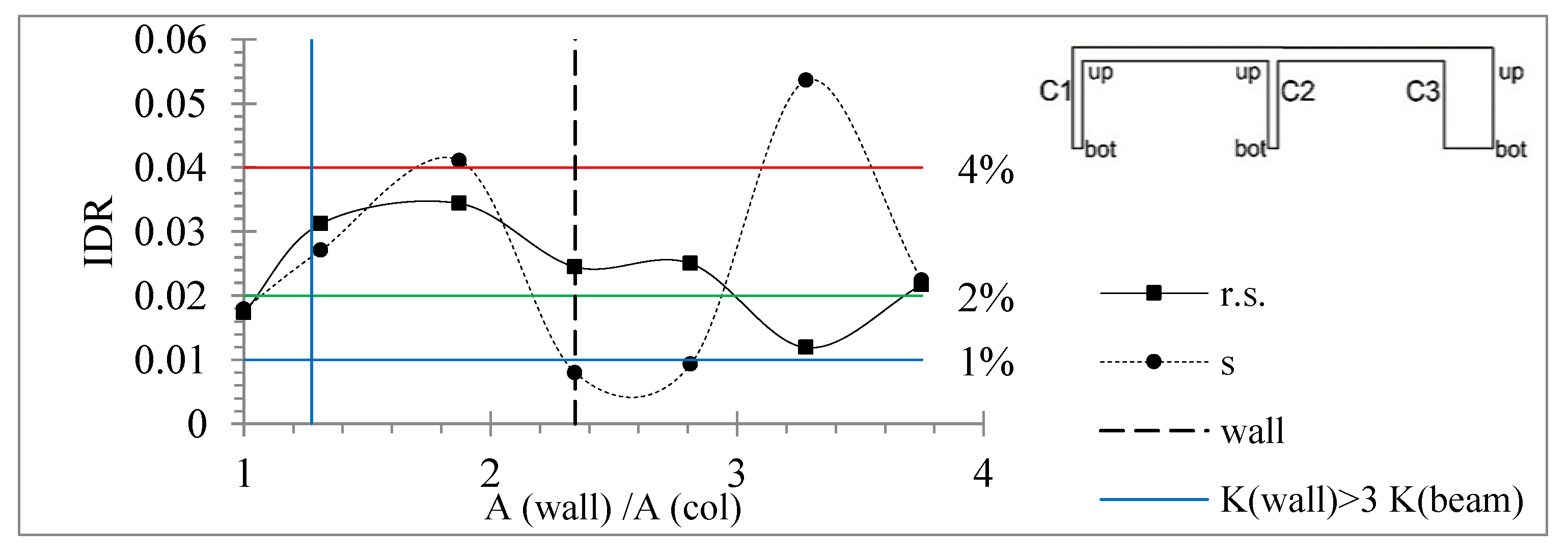
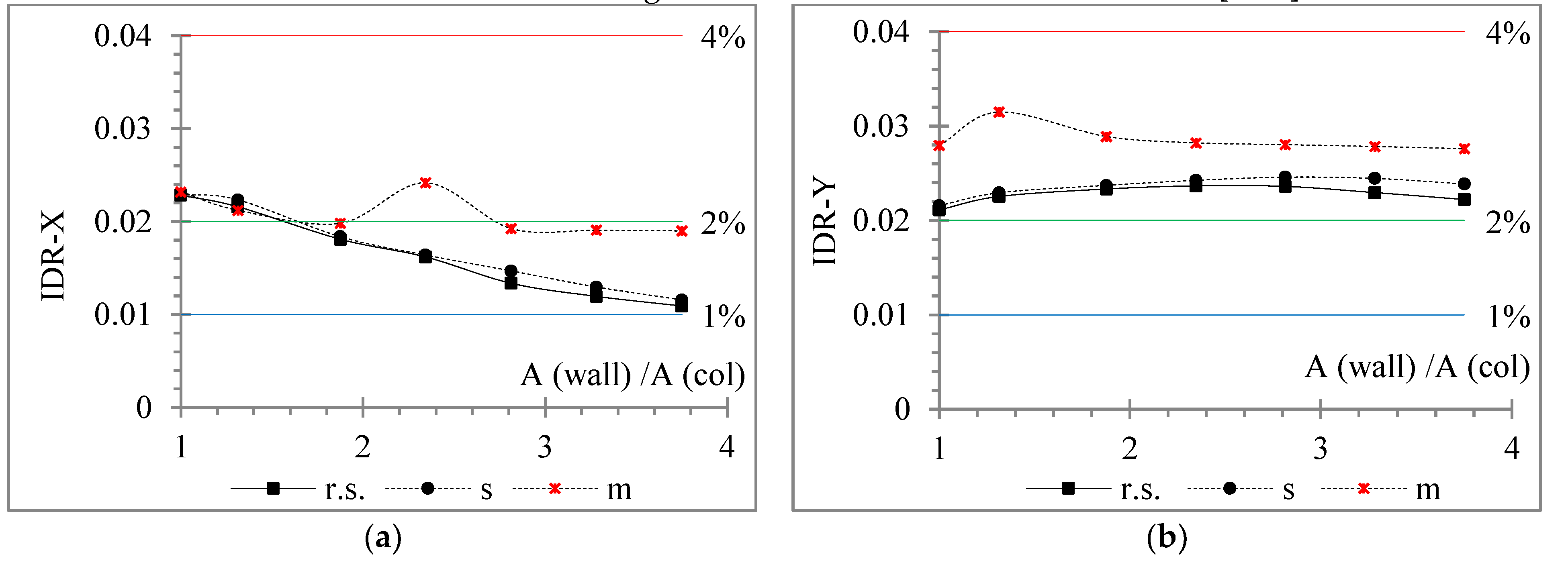
  • The IDR tends to increase due to SSI, more for the case of foundation mat than for footings with tie beams, occasionally even up to five times greater than for the rigid soil assumption.
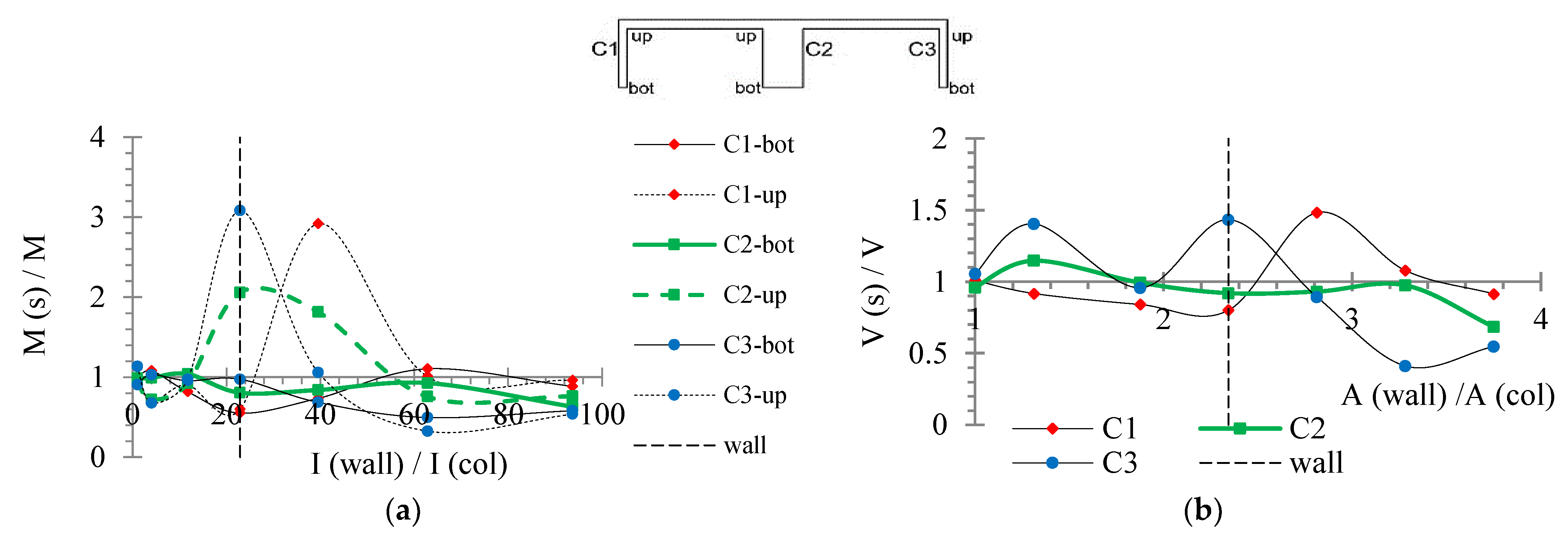
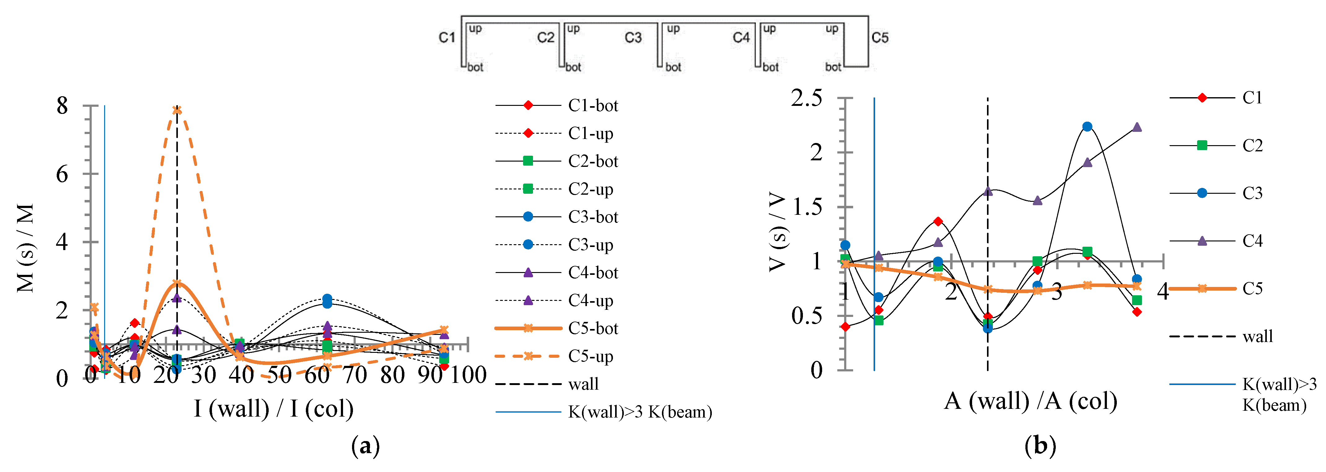
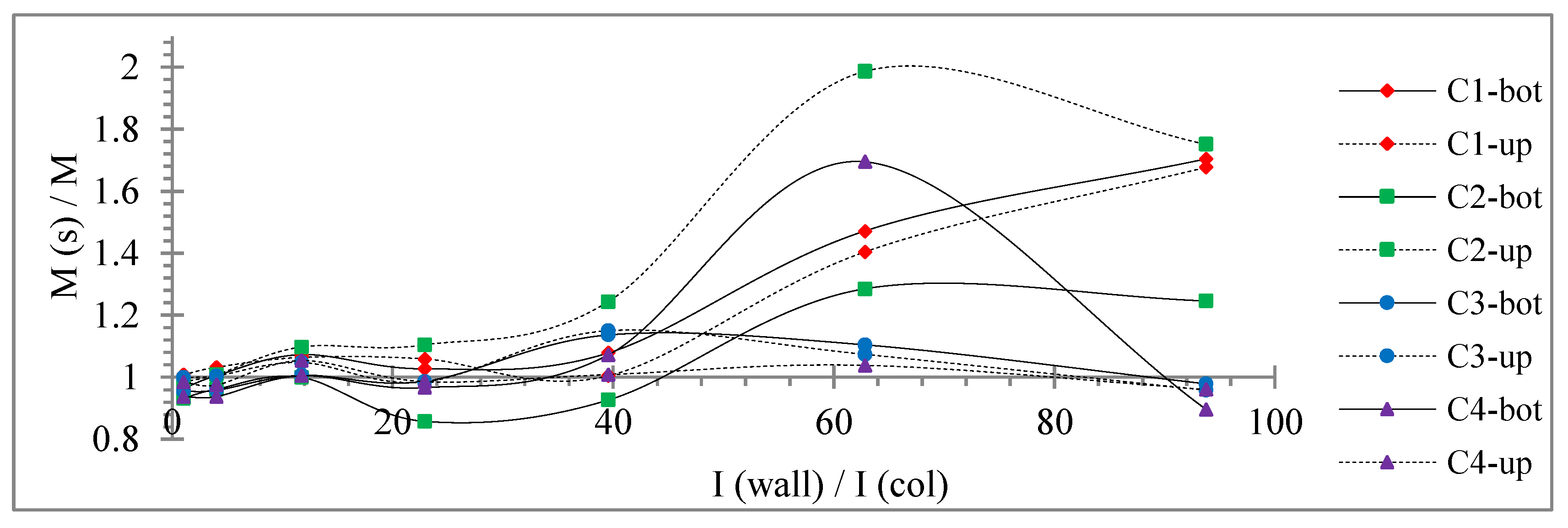
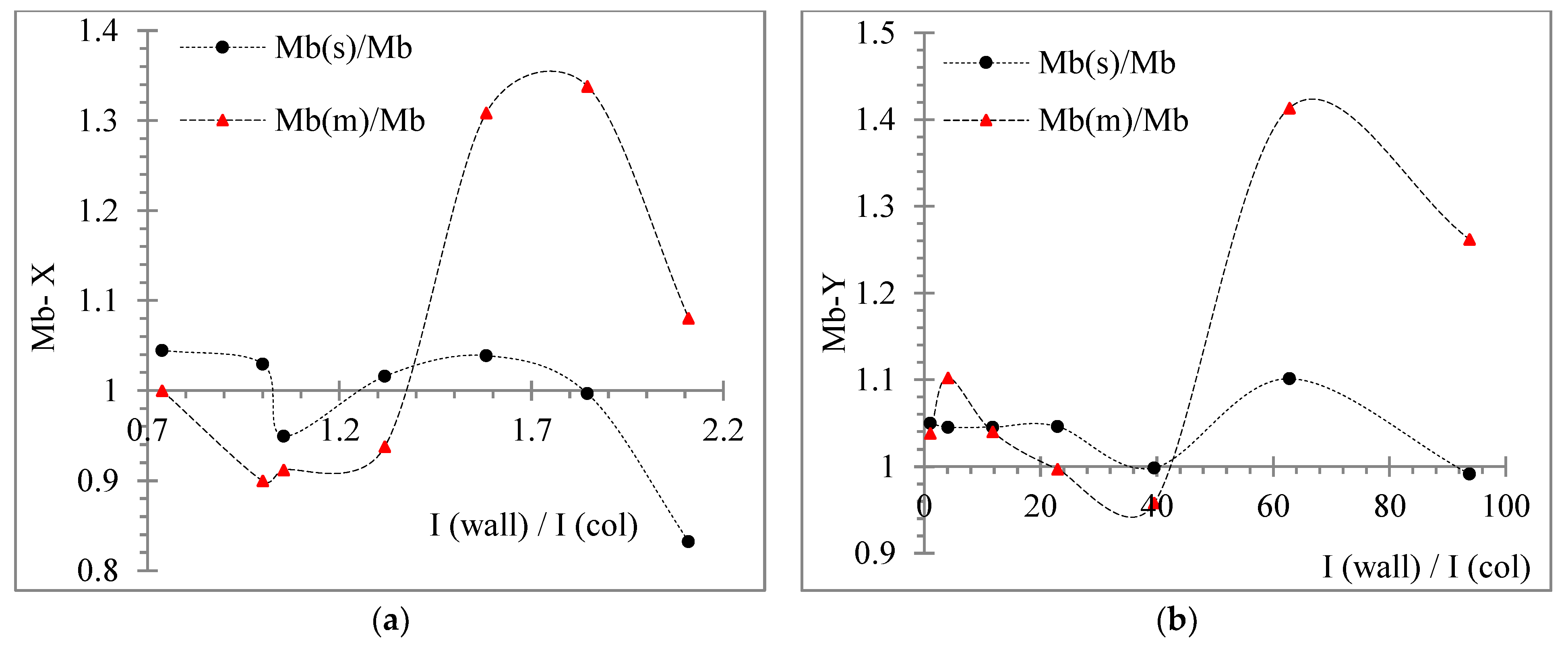
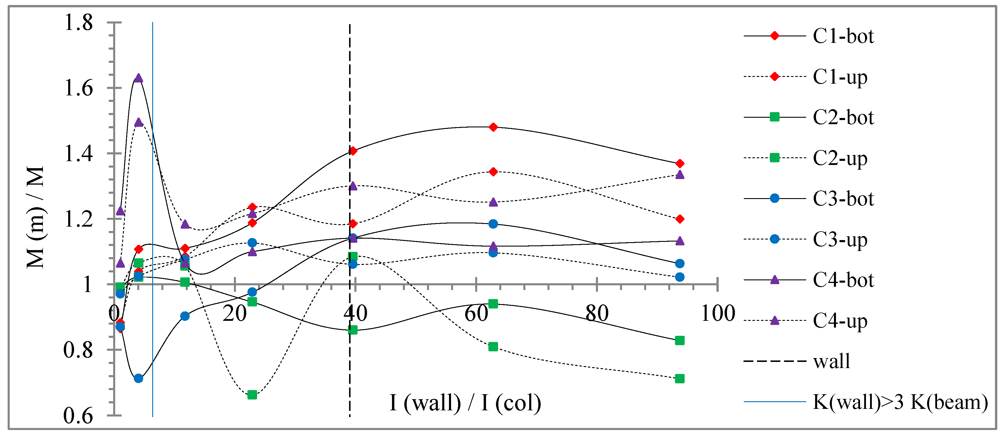
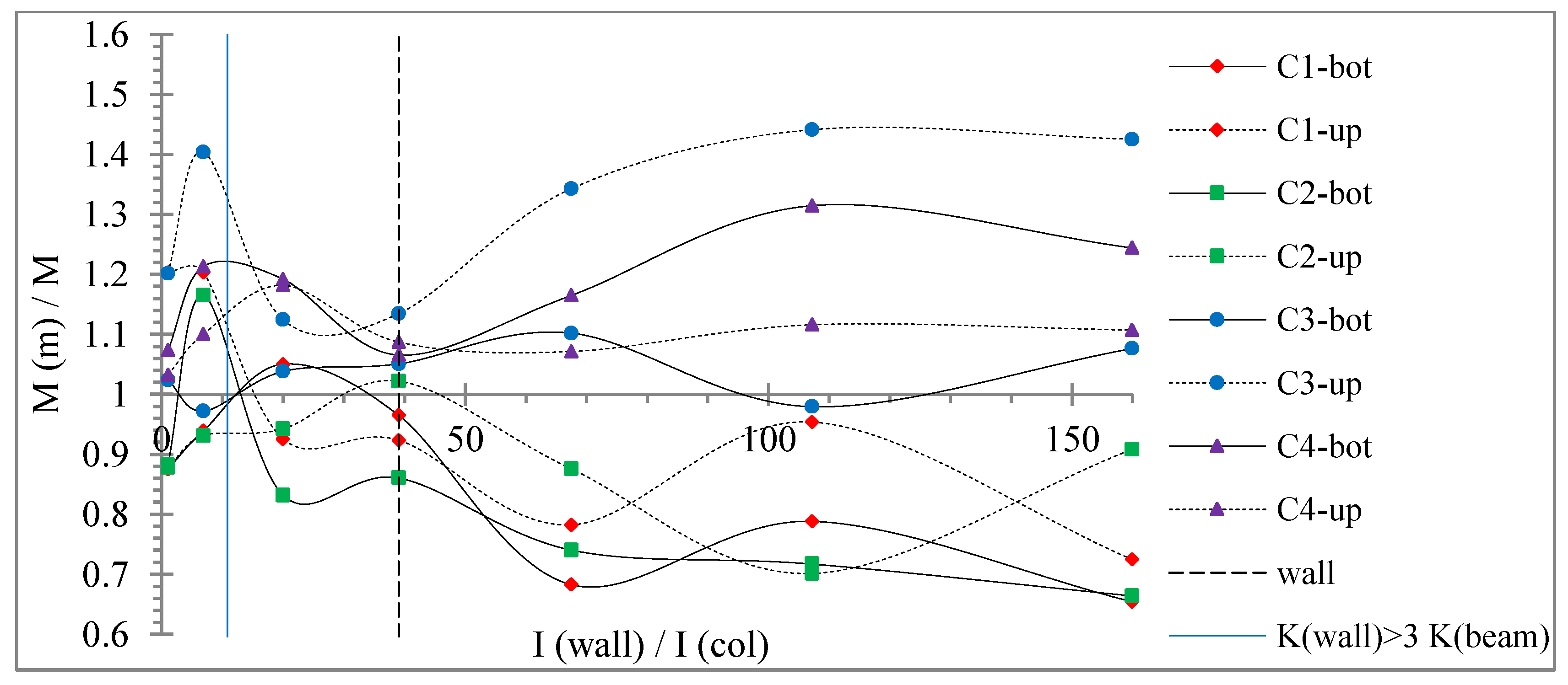
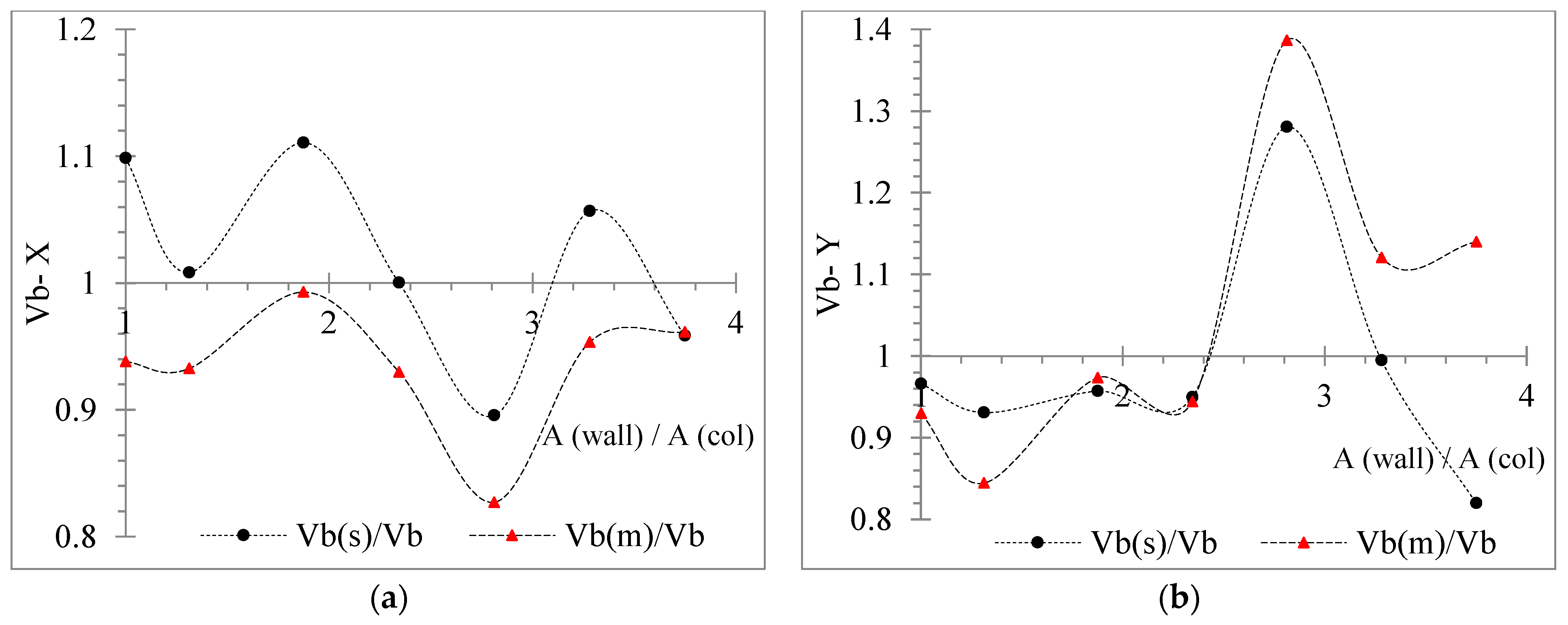
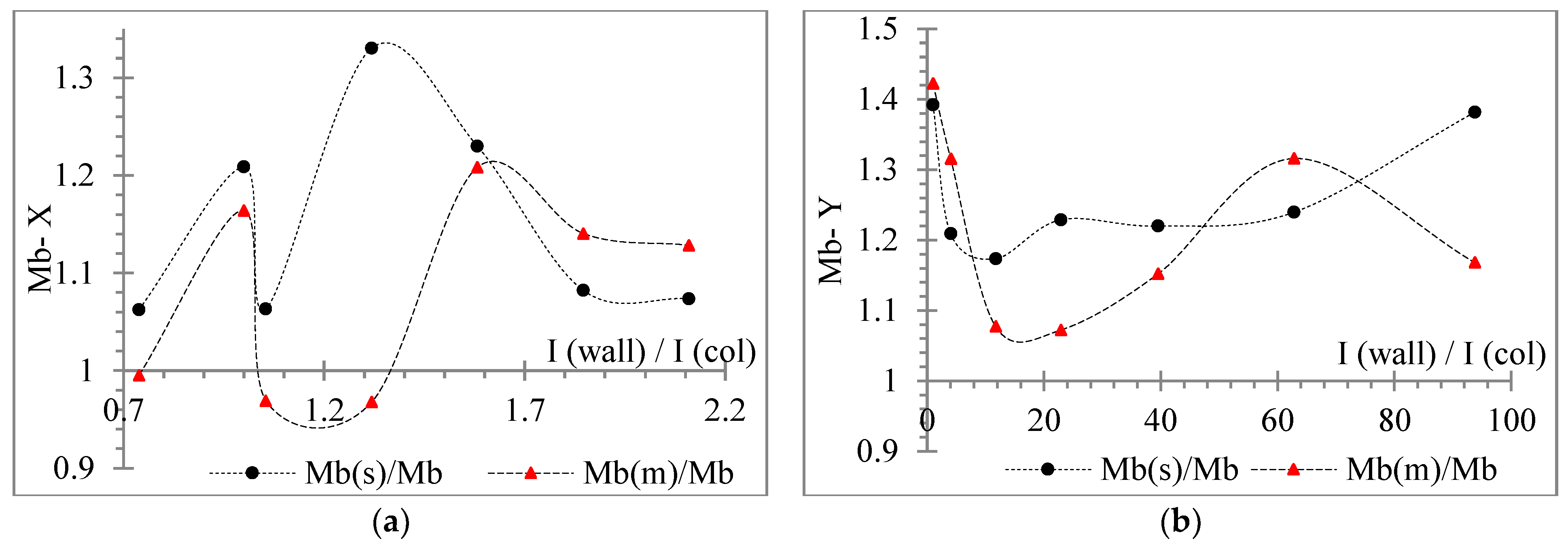
  • Considering the ratios of the internal bending moment and shear force of the vertical R/C elements, the columns tend to be stressed due to SSI, while the wall tends to be relieved. Indicatively, an increase in the ratio of the internal bending moment due to SSI up to 1.7 times and of the ratio of the shear force up to 2 times, as compared to the rigid soil, can be observed. In the 3D buildings, column C1, which is connected by an R/C beam to the wall along with the major local axis, seems to be overwhelmed more than the rest columns.
  • SSI affects variably the internal torque ratio of the vertical elements, in a different way for each earthquake, incidence angle and storey.
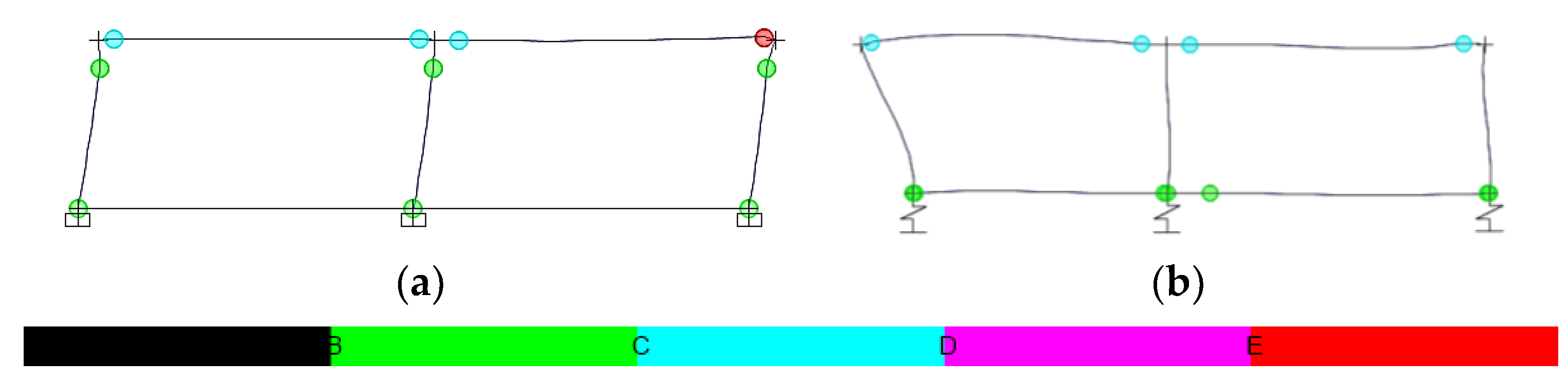
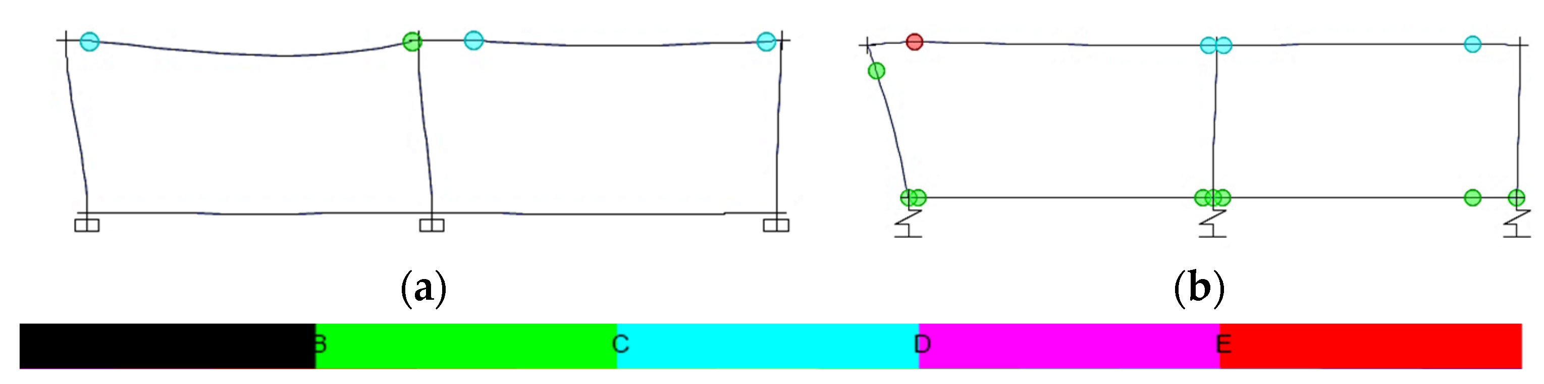
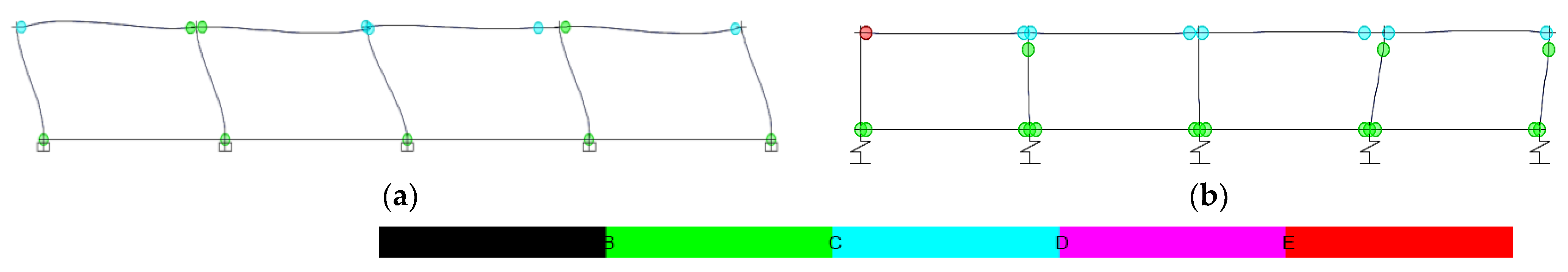
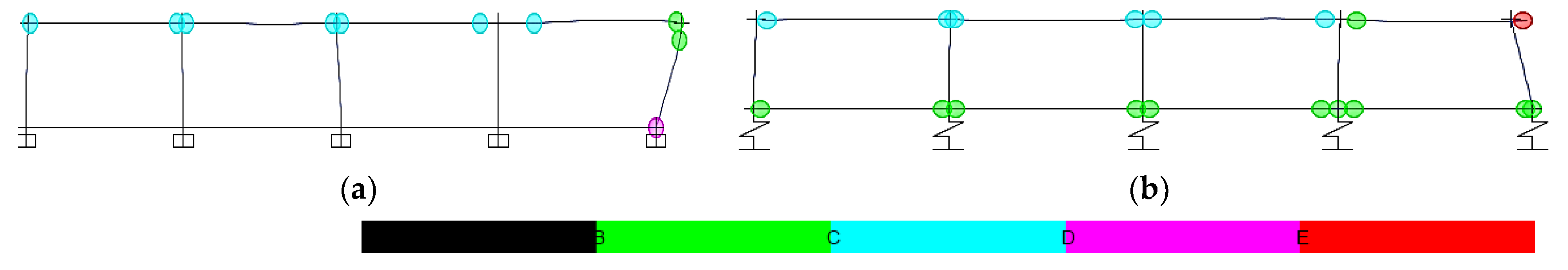
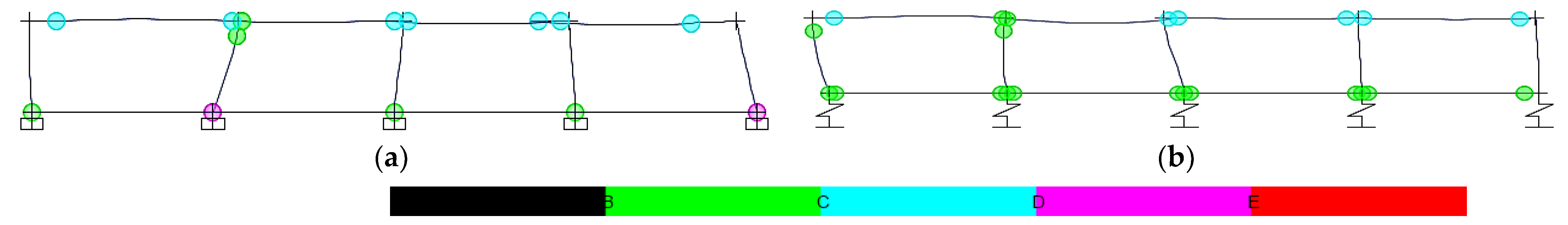
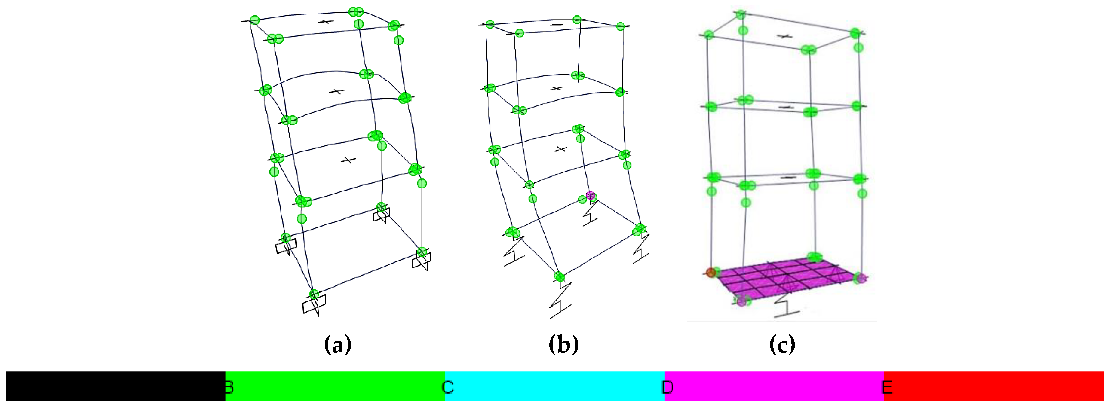
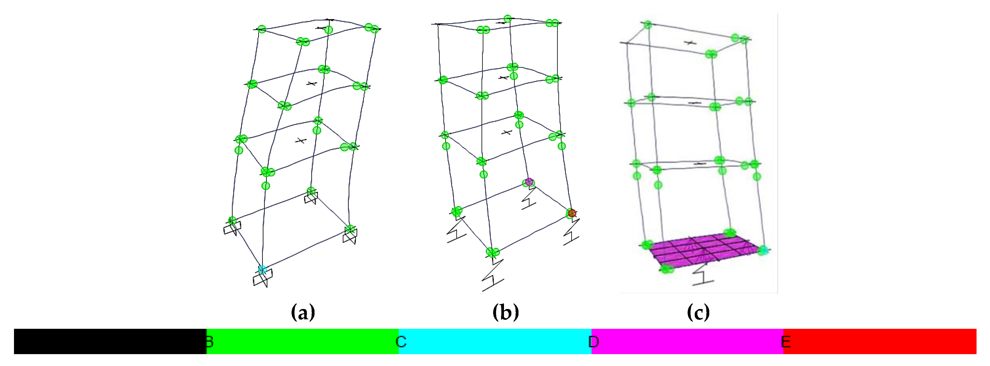
  • The top section of vertical elements is stressed more than the respective bottom section due to SSI, in terms of the internal bending moment ratio and by observations of the elastoplastic hinge behaviour, where a shift to a worse performance level tends to be observed for SSI, as compared to the rigid soil assumption.
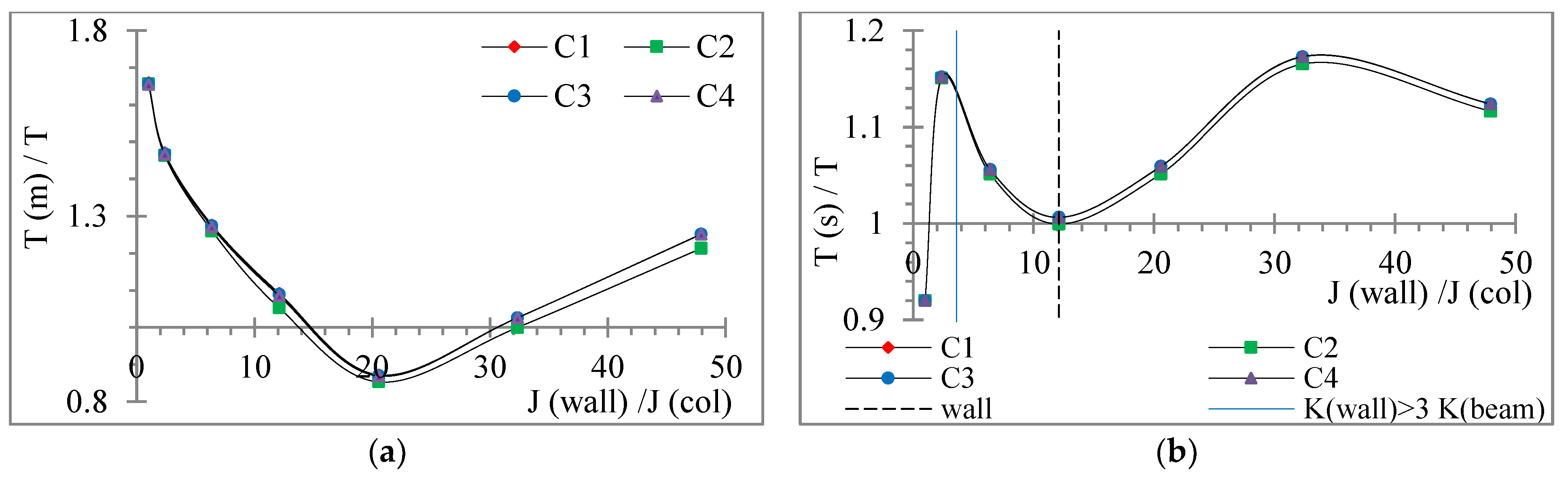
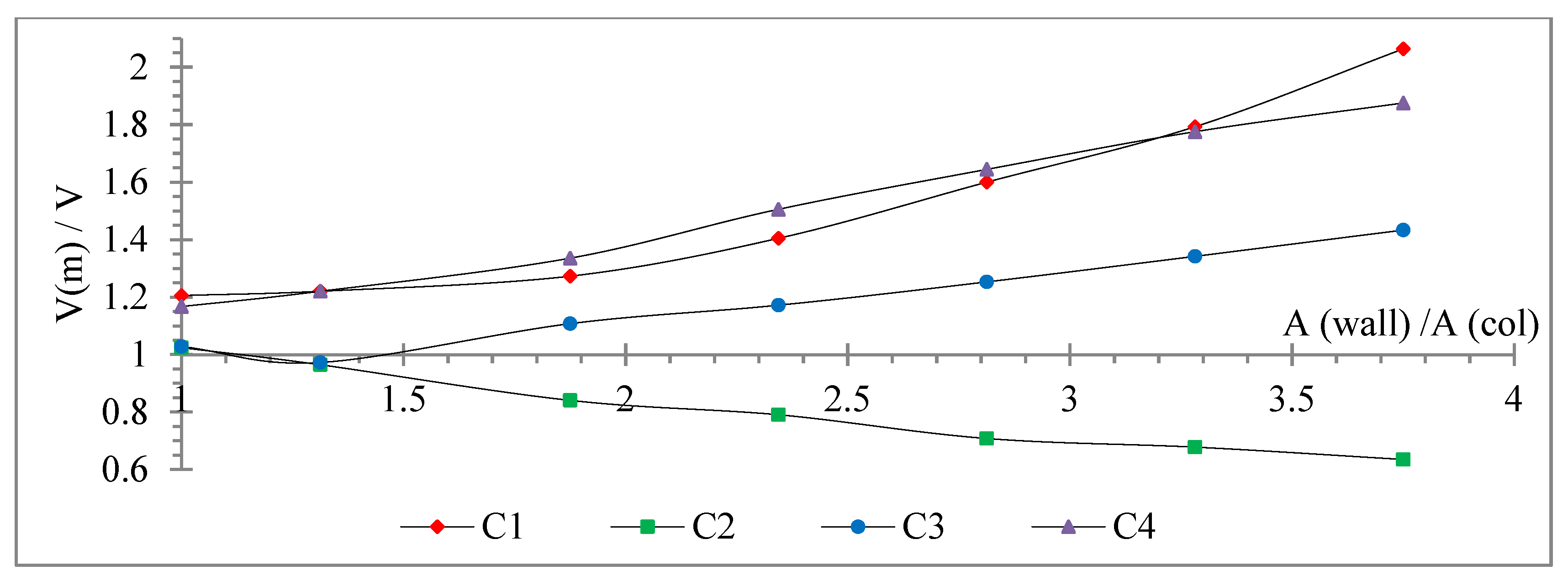
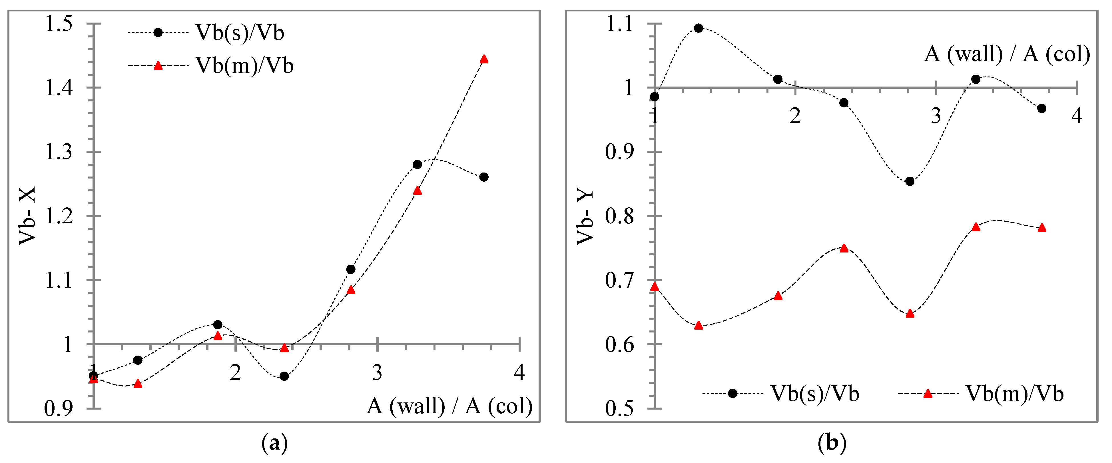
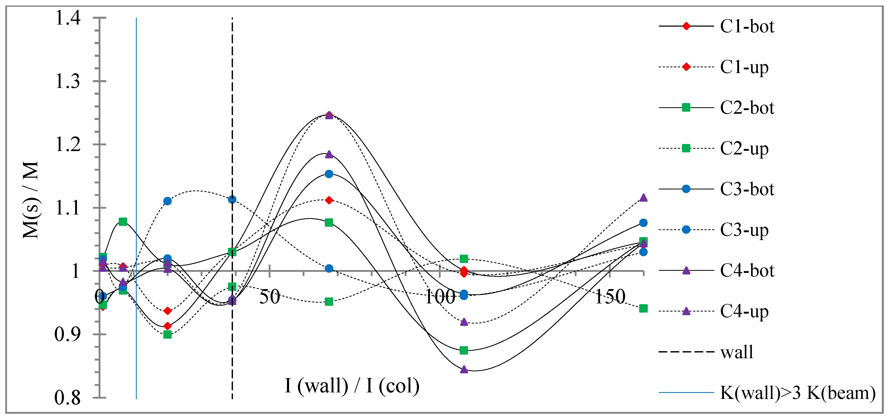
  • The storey force, moment and torque ratios are strongly affected by SSI, showing fluctuating plots, tending to greater values for foundation mat than for footings, as compared to rigid soil, e.g., even up to 1.75.
  • The symmetrical R/C building seems to be less affected by SSI in terms of smaller but noticeable values of the dimensionless ratios of internal and storey forces, and occasionally for the rest response plots.
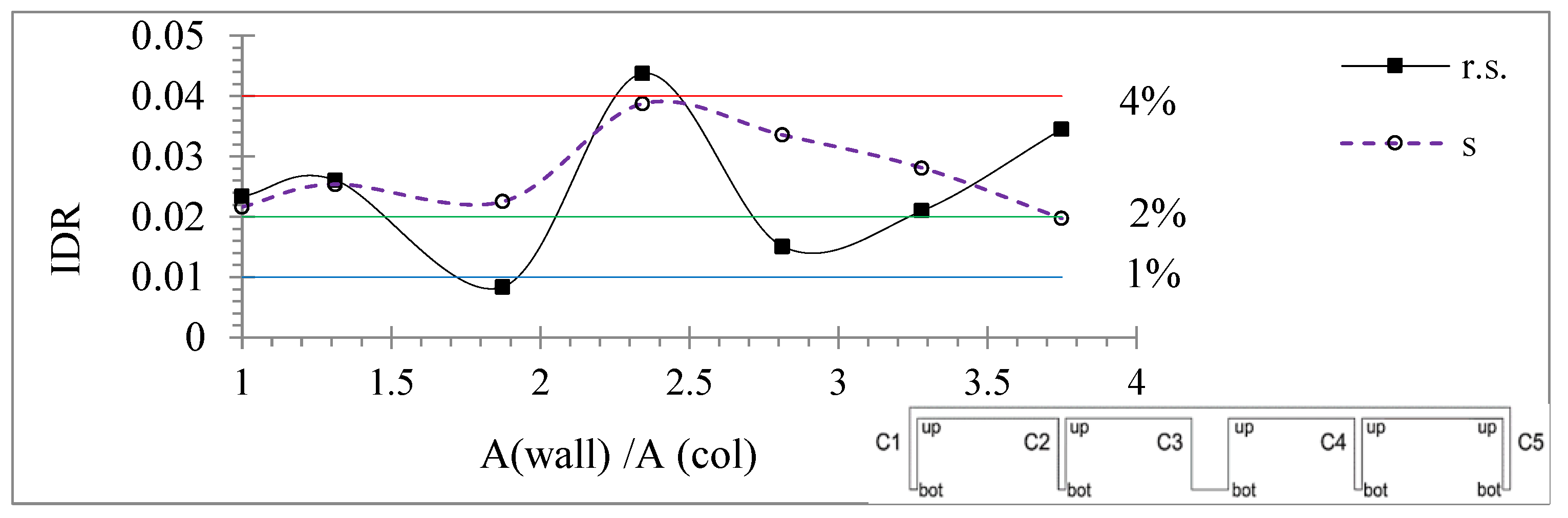
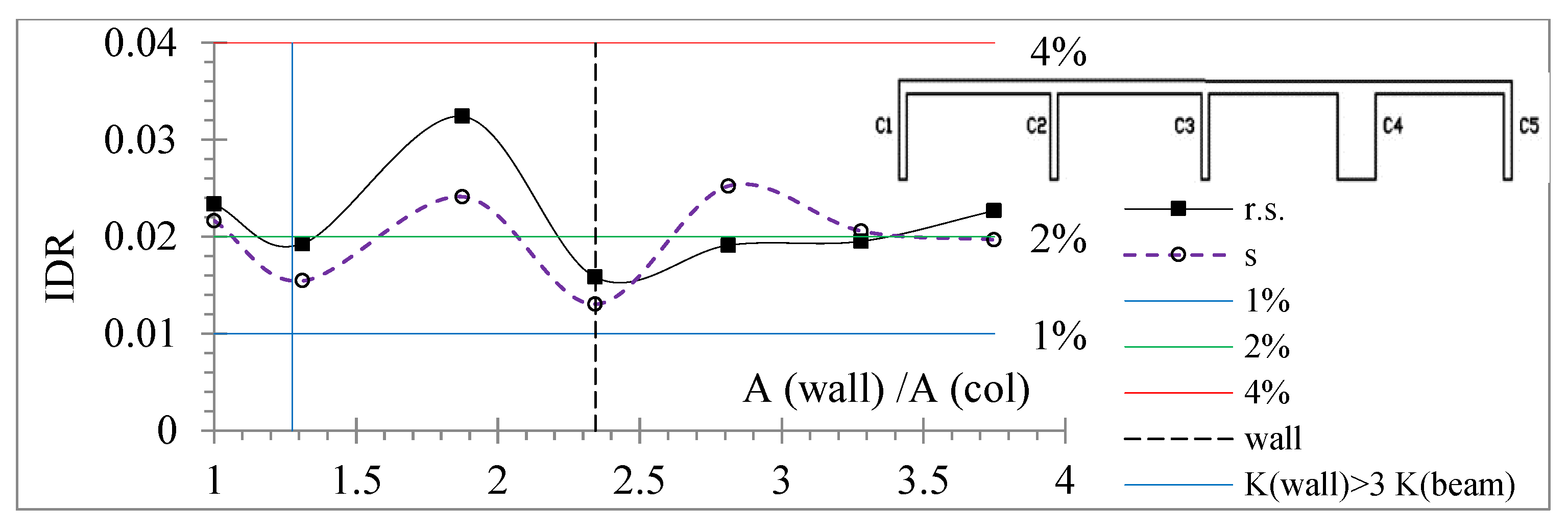
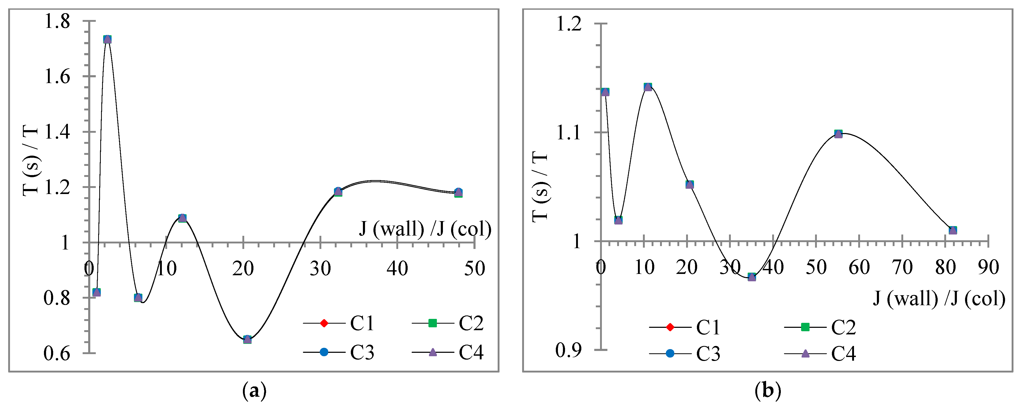
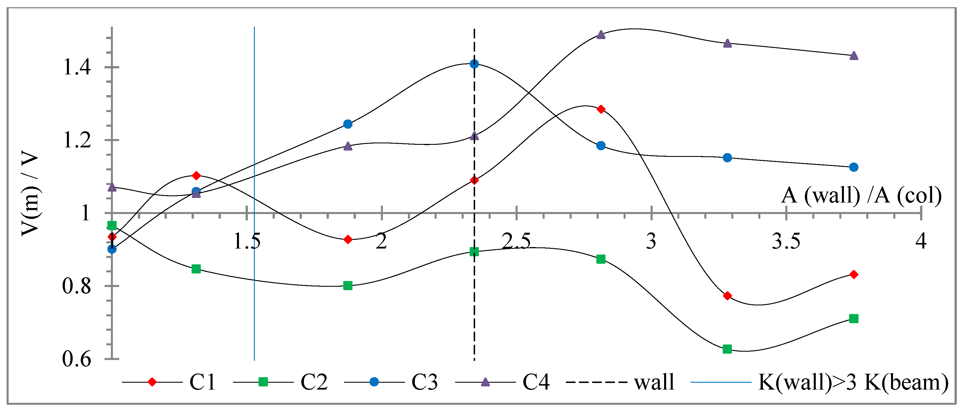
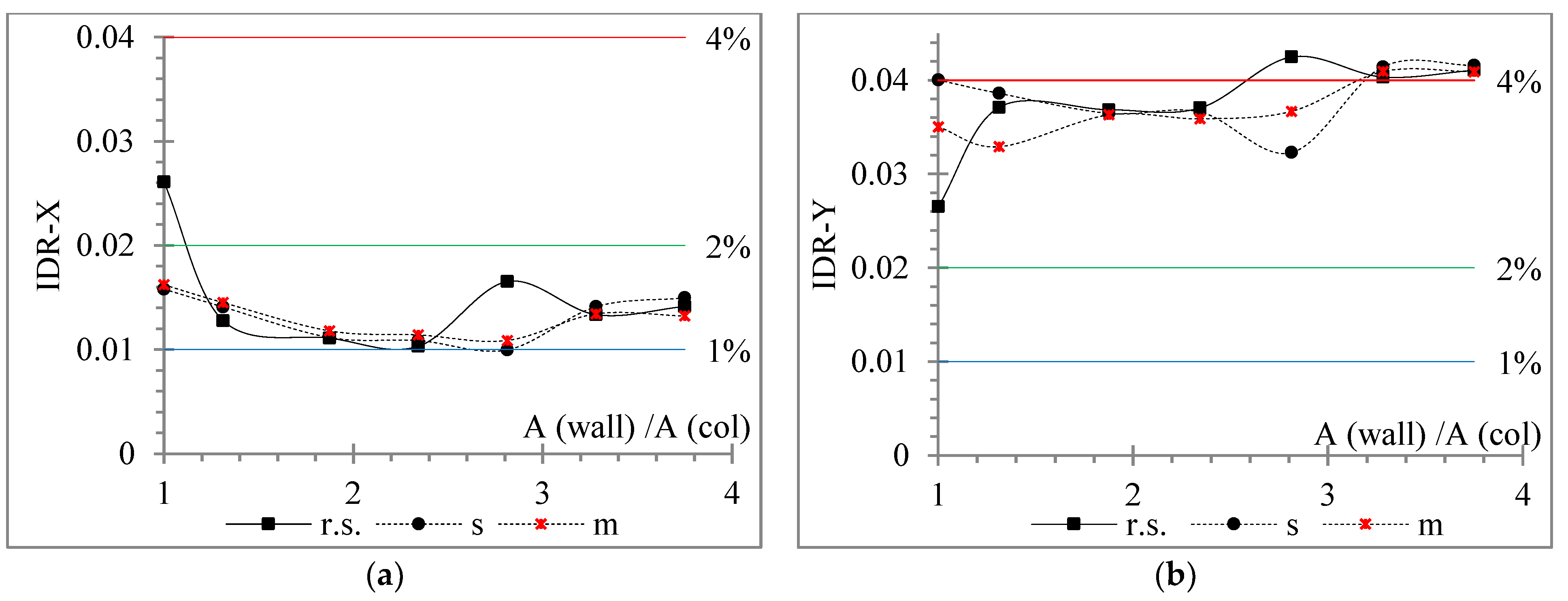
  • The geometrical “wall” limit cross-section, according to the current design codes, tends to behave as a limit of the response plots, where the latter SSI effect is yet unidentified from the current codes. Thus, for wall sections smaller than this “wall” limit, the seismic structural non-linear behaviour tends to be harmed more from SSI than for greater wall sections.
  • At the 3D frames, the earthquake incidence angle affects each examined parameter differently, without being able to separate the most critical earthquake incidence angle on the structural seismic response.
  • The SSI affects more the seismic behaviour of the lower storey of the three-storey buildings than the upper stories.
SSI is found to strongly modify the estimated seismic behaviour of R/C low-rise buildings not only with a relieving effect but also with a detrimental one, based on the various response parameters, as compared to the typical rigid base assumption. At least, the inclusion of even a simple SSI model should be suggested in the seismic design and analysis of common, low-rise R/C buildings.

Author Contributions

Conceptualization, P.K.A. and D.L.K.; methodology, P.K.A. and D.L.K.; software, P.K.A. and D.L.K.; validation, P.K.A. and D.L.K.; formal analysis, P.K.A. and D.L.K.; investigation, P.K.A. and D.L.K.; resources, P.K.A. and D.L.K.; data curation, P.K.A. and D.L.K.; writing—original draft preparation, P.K.A. and D.L.K.; writing—review and editing, P.K.A. and D.L.K.; visualization, P.K.A. and D.L.K.; supervision, P.K.A. and D.L.K.; project administration, P.K.A. and D.L.K.; funding acquisition, P.K.A. and D.L.K. All authors have read and agreed to the published version of the manuscript.

Funding

This research received no external funding.

Institutional Review Board Statement

Not applicable.

Informed Consent Statement

Not applicable.

Data Availability Statement

The data presented in this study are available in the article.

Conflicts of Interest

The authors declare no conflict of interest.

References

  1. EN 1998-1; Eurocode 8: Design of Structures for Earthquake Resistance—Part 1: General Rules, Seismic Actions and Rules for Buildings, Part 3: Strengthening and Repair of Buildings, Part 5: Foundations, Retaining Structures and Geotechnical Aspects, Part 6: Towers, Masts and Chimneys; European Committee for Standardization: Brussels, Belgium, 2004.
  2. Mylonakis, G.; Syngros, C.; Gazetas, G.; Tazoh, T. The role of soil in the collapse of 18 piers of Hanshin Expressway in the Kobe earthquake. Earthq. Eng. Struct. Dyn. 2006, 35, 547–575. [Google Scholar] [CrossRef]
  3. Mylonakis, G.; Gazetas, G. Seismic soil-structure interaction: Beneficial or detrimental? J. Earthq. Eng. 2000, 4, 277–301. [Google Scholar] [CrossRef]
  4. Anand, V.; Kumar, S.R. Seismic soil-structure interaction: A state-of-the-art review. Structures 2018, 16, 317–326. [Google Scholar] [CrossRef]
  5. Barnaure, M.; Manoli, D. Unfavourable seismic behaviour of reinforced concrete structures due to soil structure interaction. IOP Conf. Ser. Earth Environ. Sci. 2019, 362, 12119. [Google Scholar] [CrossRef]
  6. Mantzaras, G.; Karabalis, D.L. The role of SSI in the redistribution of internal forces in concrete buildings due to seismic excitation. In Proceedings of the COMPDYN 2015, Crete Island, Greece, 25–27 May 2015. [Google Scholar]
  7. Askouni, P.K.; Karabalis, D.L. SSI effects on the redistribution of seismic forces in one-storey R/C buildings. Earthq. Struct. 2021, 20, 261–278. [Google Scholar] [CrossRef]
  8. Askouni, P.K.; Karabalis, D.L. SSI influence on the seismic response of asymmetrical small, low-rise R/C buildings. Structures 2021, 32, 1355–1373. [Google Scholar] [CrossRef]
  9. Askouni, P.K. Seismic Force Redistribution in Asymmetrical Reinforced Concrete Buildings Due to Soil-Structure Interaction. Ph.D. Thesis, University of Patras, Patras, Greece, 14 July 2020. [Google Scholar]
  10. Mourlas, C.; Gravett, D.Z.; Markou, G.; Papadrakakis, M. Investigation of the soil structure interaction effect on the dynamic behavior of multistorey RC buildings. In Proceedings of the VIII International Conference on Computational Methods for Coupled Problems in Science and Engineering, COUPLED PROBLEMS 2019, Barcelona, Spain, 3–5 June 2019. [Google Scholar]
  11. Oz, I.; Senel, S.M.; Palanci, M.; Kalkan, A. Effect of soil-structure interaction on the seismic response of existing low and mid-rise RC buildings. Appl. Sci. 2020, 10, 8357. [Google Scholar] [CrossRef]
  12. Tomeo, R.; Bilotta, A.; Pitilakis, D.; Nigro, E. Soil-structure interaction effects on the seismic performances of reinforced concrete moment resisting frames. Procedia Eng. 2017, 199, 230–235. [Google Scholar] [CrossRef]
  13. Arapakou, A.E.; Papadopoulos, V.P. Effects of Soil Simulation on the Interaction Analyses of Framed Structures Under 2-D and 3-D Conditions. Geotech. Geol. Eng. 2020, 38, 5389–5407. [Google Scholar] [CrossRef]
  14. NIST GCR 12-917-21; NEHRP Consultants Joint Venture, Soil-Structure Interaction for Building Structures. NIST (National Institute of Standards and Technology); U.S. Department of Commerce: Gaithersburg, MD, USA, 2012. Available online: https://www.nehrp.gov/pdf/nistgcr12-917-21.pdf (accessed on 17 June 2022).
  15. Rutenberg, A.; Tso, W.K.; Heidebrecht, A.C. Dynamic properties of asymmetric wall-frame structures. Earthq. Eng. Struct. Dyn. 1977, 5, 41–51. [Google Scholar] [CrossRef]
  16. De La Llera, J.C.; Chopra, A.K. Accidental torsion in buildings due to stiffness uncertainty. Earthq. Eng. Struct. Dyn. 1994, 23, 117–136. [Google Scholar] [CrossRef]
  17. De La Llera, J.C.; Chopra, A.K. Using accidental eccentricity in code-specified static and dynamic analyses of buildings. Earthq. Eng. Struct. Dyn. 1994, 23, 947–967. [Google Scholar] [CrossRef]
  18. De La Llera, J.C.; Chopra, A.K. A simplified model for analysis and design of asymmetric-plan buildings. Earthq. Eng. Struct. Dyn. 1995, 24, 573–594. [Google Scholar] [CrossRef]
  19. De La Llera, J.C.; Chopra, A.K. Understanding the inelastic seismic behaviour of asymmetric-plan buildings. Earthq. Eng. Struct. Dyn. 1995, 24, 549–572. [Google Scholar] [CrossRef]
  20. Bosco, M.; Marino, E.M.; Rossi, P.P. An analytical method for the evaluation of the in-plan irregularity of non-regularly asymmetric buildings. Bull. Earthq. Eng. 2013, 11, 1423–1445. [Google Scholar] [CrossRef]
  21. Bosco, M.; Ferrara, G.A.; Ghersi, A.; Marino, E.M.; Rossi, P.P. Application of Nonlinear Static Method with Corrective Eccentricities to Multistorey Buildings: A Case Study. In Seismic Behaviour and Design of Irregular and Complex Civil Structures I, 1st ed.; Lavan, O., De Stefano, M., Eds.; Springer Science+Business Media: Dordrecht, The Netherlands, 2013; Volume 4, pp. 173–188. [Google Scholar] [CrossRef]
  22. Bosco, M.; Ghersi, A.; Marino, E.M.; Rossi, P.P. Comparison of nonlinear static methods for the assessment of asymmetric buildings. Bull. Earthq. Eng. 2013, 11, 2287–2308. [Google Scholar] [CrossRef]
  23. Jiang, X.; Kuang, Y. Inelastic parametric analysis of two-way asymmetrical multi-storey buildings. Adv. Struct. Eng. 2016, 19, 806–824. [Google Scholar] [CrossRef]
  24. Khatiwada, P.; Lumantarna, E.; Lam, N.; Looi, D. Fast Checking of Drift Demand in Multi-Storey Buildings with Asymmetry. Buildings 2020, 11, 13. [Google Scholar] [CrossRef]
  25. Köber, D.; De Stefano, M.; Zembaty, Z. Seismic Behaviour and Design of Irregular and Complex Civil Structures III, 1st ed.; Springer Nature: Cham, Switzerland, 2020. [Google Scholar] [CrossRef]
  26. Zembaty, Z.; De Stefano, M. Seismic Behaviour and Design of Irregular and Complex Civil Structures II; Springer International Publishing: Cham, Switzerland, 2016. [Google Scholar] [CrossRef]
  27. Stathopoulos, K.G.; Anagnostopoulos, S.A. Accidental design eccentricity: Is it important for the inelastic response of buildings to strong earthquakes? Soil Dyn. Earthq. Eng. 2010, 30, 782–797. [Google Scholar] [CrossRef]
  28. Anagnostopoulos, S.A.; Kyrkos, M.T.; Stathopoulos, K.G. Earthquake induced torsion in buildings: Critical review and state of the art. Earthq. Struct. 2015, 8, 305–377. [Google Scholar] [CrossRef] [Green Version]
  29. Pilarska, D.; Maleska, T. Numerical Analysis of Steel Geodesic Dome under Seismic Excitations. Materials 2021, 14, 4493. [Google Scholar] [CrossRef] [PubMed]
  30. Fan, F.; Zhi, X.; Li, W. Analysis of the Acceleration Response Spectra of Single-Layer Spherical Reticulated Shell Structures. Appl. Sci. 2022, 12, 2116. [Google Scholar] [CrossRef]
  31. Nair, D.; Ichihashi, K.; Terazawa, Y.; Sitler, B.; Takeuchi, T. Higher mode effects of multistorey substructures on the seismic response of double-layered steel gridshell domes. Eng. Struct. 2021, 243, 112677. [Google Scholar] [CrossRef]
  32. Roopa, M.; Venugopal, H.J.; Nagaral, M. Soil Structure Interaction Analysis of a Single Layer Latticed Geodesic Dome. Indian J. Sci. Technol. 2022, 15, 292–299. [Google Scholar] [CrossRef]
  33. Karavasilis, T.L.; Rizos, D.C.; Karabalis, D.L. Seismic analysis of spherical tanks including fluid-structure-soil interaction. In Proceedings of the 13th World Conference on Earthquake Engineering, Vancouver, BC, Canada, 1–6 August 2004. [Google Scholar]
  34. Bhargava, K.; Ghosh, A.K.; Agrawal, M.K.; Patnaik, R.; Ramanujam, S.; Kushwaha, H.S. Evaluation of seismic fragility of structures—A case study. Nucl. Eng. Des. 2002, 212, 253–272. [Google Scholar] [CrossRef] [Green Version]
  35. Talaslidis, D.G.; Manolis, G.D.; Paraskevopoulos, E.; Panagiotopoulos, C.; Pelekasis, N.; Tsamopoulos, J.A. Risk analysis of industrial structures under extreme transient loads. Soil Dyn. Earthq. Eng. 2004, 24, 435–448. [Google Scholar] [CrossRef]
  36. Kumar, S.; Raychowdhury, P.; Gundlapalli, P. Response analysis of a nuclear containment structure with nonlinear soil–structure interaction under bi-directional ground motion. Int. J. Adv. Struct. Eng. IJASE 2015, 7, 211–221. [Google Scholar] [CrossRef] [Green Version]
  37. Athanatopoulou, A.M. Critical orientation of three correlated seismic components. Eng. Struct. 2005, 27, 301–312. [Google Scholar] [CrossRef]
  38. Fontara, I.K.M.; Kostinakis, K.G.; Manoukas, G.E.; Athanatopoulou, A.M. Parameters affecting the seismic response of buildings under bi-directional excitation. Struct. Eng. Mech. 2015, 53, 957–979. [Google Scholar] [CrossRef]
  39. Kostinakis, K.G.; Manoukas, G.E.; Athanatopoulou, A.M. Influence of seismic incident angle on response of symmetric in plan buildings. KSCE J. Civ. Eng. 2018, 22, 725–735. [Google Scholar] [CrossRef]
  40. Altunişik, A.C.; Kalkan, E. Earthquake incidence angle influence on seismic performance of reinforced concrete buildings. Sigma J. Eng. Nat. Sci. 2017, 35, 609–631. [Google Scholar]
  41. Tsourekas, A.; Athanatopoulou, A.; Kostinakis, K. Maximum mean square response and critical orientation under bi-directional seismic excitation. Eng. Struct. 2021, 233, 111881. [Google Scholar] [CrossRef]
  42. Hussain, M.A.; Dutta, S.C.; Das, S. Seismic behaviour of structures under bidirectional ground motion: Does the angle of incidence have any influence? . Soil Dyn. Earthq. Eng. 2022, 159, 107328. [Google Scholar] [CrossRef]
  43. Eurocode 1 (EC1); Actions on Structures—Part 1-1: General Actions, Densities, Self-Weight, Imposed Loads for Buildings; European Committee for Standardization (CEN): Brussels, Belgium, 2001.
  44. Adhikari, R.; Rupakhety, R.; Giri, P.; Baruwal, R.; Subedi, R.; Gautam, R.; Gautam, D. Seismic Fragility Analysis of Low-Rise RC Buildings with Brick Infills in High Seismic Region with Alluvial Deposits. Buildings 2022, 12, 72. [Google Scholar] [CrossRef]
  45. Karayannis, C.G.; Favvata, M.J.; Kakaletsis, D.J. Seismic behaviour of infilled and pilotis RC frame structures with beam–column joint degradation effect. Eng. Struct. 2011, 33, 2821–2831. [Google Scholar] [CrossRef]
  46. Eurocode 2 (EC2); Design of Concrete Structures—Part 1-1: General Rules and Rules for Buildings; European Committee for Standardization (CEN): Brussels, Belgium, 2004.
  47. Eurocode 7 (EC7); Geotechnical Design—Part 1: General Rules; European Committee for Standardization (CEN): Brussels, Belgium, 2003.
  48. Sfakianakis, M.G. Biaxial bending with axial force of reinforced, composite and repaired concrete sections of arbitrary shape by fiber model and computer graphics. Adv. Eng. Softw. 2002, 33, 227–242. [Google Scholar] [CrossRef]
  49. Sfakianakis, M.G. Computation of Yield and Failure Surfaces for Biaxial Bending with Axial Force of Reinforced Concrete Sections with Jackets. In Proceedings of the 15 WCEE2012, Lisbon, Portugal, 24–28 September 2012. [Google Scholar]
  50. Sfakianakis, M.G.; Fardis, M.N. Nonlinear finite element for modeling reinforced concrete columns in three-dimensional dynamic analysis. Comput. Struct. 1991, 40, 1405–1419. [Google Scholar] [CrossRef]
  51. Fardis, M.N. Seismic Design, Assessment and Retrofitting of Concrete Buildings: Based on EN-Eurocode 8, 1st ed.; Springer: Berlin/Heidelberg, Germany, 2009. [Google Scholar]
  52. Fardis, M.; Carvalho, E.; Fajfar, P.; Pecker, A. Seismic Design of Concrete Buildings to Eurocode 8, 1st ed.; Crc Press: Boca Raton, FL, USA, 2015. [Google Scholar]
  53. Karabalis, D.L.; Beskos, D.E. Dynamic response of 3-D flexible foundations by time domain BEM and FEM. Int. J. Soil Dyn. Earthq. Eng. 1985, 4, 91–101. [Google Scholar] [CrossRef]
  54. Spyrakos, C.C.; Beskos, D.E. Dynamic response of flexible strip-foundations by boundary and finite elements. Soil Dyn. Earthq. Eng. 1986, 5, 84–96. [Google Scholar] [CrossRef]
  55. Qian, J.; Beskos, D.E. Dynamic interaction between 3-D rigid surface foundations and comparison with the ATC-3 provisions. Earthq. Eng. Struct. Dyn. 1995, 24, 419–437. [Google Scholar] [CrossRef]
  56. Karabalis, D.L. Non-singular time domain BEM with applications to 3D inertial soil–structure interaction. Soil Dyn. Earthq. Eng. 2004, 24, 281–293. [Google Scholar] [CrossRef]
  57. Kamal, M.; Inel, M. Correlation between Ground Motion Parameters and Displacement Demands of Mid-Rise RC Buildings on Soft Soils Considering Soil-Structure-Interaction. Buildings 2021, 11, 125. [Google Scholar] [CrossRef]
  58. Khosravifardshirazi, A.; Johari, A.; Javadi, A.A.; Khanjanpour, M.H.; Khosravifardshirazi, B.; Akrami, M. Role of Subgrade Reaction Modulus in Soil-Foundation-Structure Interaction in Concrete Buildings. Buildings 2022, 12, 540. [Google Scholar] [CrossRef]
  59. Mayoral, J.M.; Tepalcapa, S.; Roman-de la Sancha, A.; El Mohtar, C.S.; Rivas, R. Ground subsidence and its implication on building seismic performance. Soil Dyn. Earthq. Eng. 2019, 126, 105766. [Google Scholar] [CrossRef]
  60. Luque, R.; Bray, J.D. Dynamic soil-structure interaction analyses of two important structures affected by liquefaction during the Canterbury earthquake sequence. Soil Dyn. Earthq. Eng. 2020, 133, 106026. [Google Scholar] [CrossRef]
  61. Agalianos, A.; Anastasopoulos, I. Numerical analysis of surface foundation subjected to strike-slip faulting: Model boundaries, pre-softening volumetric response, parametric study. Soil Dyn. Earthq. Eng. 2021, 151, 106979. [Google Scholar] [CrossRef]
  62. Gazetas, G. Analysis of machine foundation vibrations: State of the art. Int. J. Soil Dyn. Earthq. Eng. 1983, 2, 2–42. [Google Scholar] [CrossRef]
  63. ETABS. Integrated Building Design Software; Computers and Structures Inc. CSI: Berkeley, CA, USA, 2015. [Google Scholar]
  64. Institute of Engineering Seismology and Earthquake Engineering (ITSAK). Institute of Engineering Seismology and Earthquake Engineering. Database of Earthquake Records. Available online: http://www.itsak.gr/db/data (accessed on 1 December 2017).
  65. Avramidis, I.; Athanatopoulou, A.; Anastasiadis, K.; Morfidis, K. Standard Numerical Examples of Structural Analysis; Aivazi Publications: Thessaloniki, Greece, 2005. (In Greek) [Google Scholar]
  66. FEMA-356. Prestandard and Commentary for the Seismic Rehabilitation of Buildings. Washington, D.C.: Federal Emergency Management Agency, U.S.A. 2000. Available online: https://www.nehrp.gov/pdf/fema356.pdf (accessed on 1 December 2017).
  67. Greek Interventions Regulation (KANEPE), 2nd Revision, Earthquake Planning and Protection Organization (EPPO), Athens, Greece. 2017. Available online: https://www.oasp.gr/userfiles/%CE%9A%CE%91%CE%9D_%CE%95%CE%A0%CE%95__2%CE%B7%20%CE%91%CE%BD%CE%B1%CE%B8%CE%B5%CF%8E%CF%81%CE%B7%CF%83%CE%B7_2017_Final.pdf (accessed on 1 December 2018). (In Greek).
Figure 1. 2D one-storey symmetrical and asymmetrical R/C frames with (a) one, (b) two and (c) four equal spans.
Buildings 12 00975 g001
Figure 2. (a) One- and (b) three-storey 3D symmetrical and asymmetrical R/C building frames under study, with the global coordinate system.
Buildings 12 00975 g002
Figure 3. (a) 3D building frame on rigid soil and (b,c) deformable soil.
Buildings 12 00975 g003
Figure 4. Floor plan of the 3D buildings with earthquake incidence angle “φ”.
Buildings 12 00975 g004
Figure 5. IDR versus A(wall)/A(col) for the 2D frame with one span.
Buildings 12 00975 g005
Figure 6. Elastoplastic hinges for the one-span 2D symmetric frame with wall section 40/40 cm for (a) the rigid soil assumption and (b) SSI.
Buildings 12 00975 g006
Figure 7. (a) M(s)/M versus I(wall)/I(col), (b) V(s)/V versus A(wall)/A(col) for the 2D frame with two equal spans by altering the middle vertical element.
Buildings 12 00975 g007
Figure 8. Elastoplastic hinges for the two-span 2D frame by altering the middle vertical element with wall section 70/30 cm for (a) the rigid soil assumption and (b) SSI.
Buildings 12 00975 g008
Figure 9. IDR versus A(wall)/A(col) for the 2D frame with two equal spans by altering the extreme vertical element.
Buildings 12 00975 g009
Figure 10. Elastoplastic hinges for the two-span 2D frame by altering the extreme vertical element with wall section 175/30 cm for (a) the rigid soil assumption and (b) SSI.
Buildings 12 00975 g010
Figure 11. IDR versus A(wall)/A(col) for the 2D frame with four equal spans by altering the middle vertical element.
Buildings 12 00975 g011
Figure 12. Elastoplastic hinges for the 2D frame four spans by altering the middle vertical element with wall section 150/30 cm for (a) the rigid soil assumption and (b) SSI.
Buildings 12 00975 g012
Figure 13. IDR versus A(wall)/A(col) for the 2D frame with four spans by altering the 4th element.
Buildings 12 00975 g013
Figure 14. Elastoplastic hinges for the 2D symmetric frame with four spans with an equal cross-section of the vertical elements 40/40 cm for (a) the rigid soil assumption and (b) SSI.
Buildings 12 00975 g014
Figure 15. Elastoplastic hinges for the 2D frame with four spans by altering the 4th vertical element with wall section 100/30 cm for (a) the rigid soil assumption and (b) SSI.
Buildings 12 00975 g015
Figure 16. (a) M(s)/M versus I(wall)/I(col), (b) V(s)/V versus A(wall)/A(col), for the 2D frames with four equal spans by altering the extreme vertical element.
Buildings 12 00975 g016
Figure 17. Elastoplastic hinges for the 2D frame with four spans by altering the extreme vertical element with wall section 100/30 cm for (a) the rigid soil assumption and (b) SSI.
Buildings 12 00975 g017
Figure 18. M(s)/M versus I(wall)/I(col) for footings mat to rigid soil and φ = 45° (Vasiliki earthquake).
Buildings 12 00975 g018
Figure 19. (a) T(m)/T versus J(wall)/J(col) for foundation mat to rigid soil and φ = 90° (Lixouri earthquake), (b) T(s)/T versus J(wall)/J(col) for footings to rigid soil and φ = 45° (Vasiliki earthquake).
Buildings 12 00975 g019
Figure 20. V(m)/V versus A(wall)/A(col) for foundation mat to rigid soil and φ = 0° (Lixouri earthquake).
Buildings 12 00975 g020
Figure 21. (a) Vb ratio on X axis versus A(wall)/A(col) for φ = 45° (Vasiliki earthquake), (b) Vb ratio on Y axis versus A(wall)/A(col) for φ = 90° (Vasiliki earthquake).
Buildings 12 00975 g021
Figure 22. (a) Mb ratio on X axis versus I(wall)/I(col) for φ = 0° (Vasiliki earthquake), (b) Mb ratio on Y axis versus I(wall)/I(col) for φ = 0° (Vasiliki earthquake).
Buildings 12 00975 g022
Figure 23. (a) Tb ratio versus J(wall)/J(col) for φ = 90° (Vasiliki earthquake), (b) Tb ratio versus J(wall)/J(col) for φ = 90° (Lixouri earthquake).
Buildings 12 00975 g023
Figure 24. IDR on (a) X axis and (b) Y axis, A(wall)/A(col) for φ = 45° (Lixouri earthquake).
Buildings 12 00975 g024
Figure 25. Elastoplastic hinges for the one-storey symmetric building with wall section 40/40 cm for (a) the rigid soil assumption and φ = 0°, (b) footings and φ = 90°, (c) foundation mat and φ = 45° (Lixouri earthquake).
Buildings 12 00975 g025
Figure 26. Elastoplastic hinges for the one-storey building with wall section 100/30 cm for (a) the rigid soil assumption and φ = 0°, (b) footings and φ = 90°, (c) foundation mat and φ = 45° (Lixouri earthquake).
Buildings 12 00975 g026
Figure 27. Elastoplastic hinges for the one-storey building with wall section 200/30 cm for (a) the rigid soil assumption and φ = 0°, (b) footings and φ = 45°, (c) foundation mat and φ = 90° (Lixouri earthquake).
Buildings 12 00975 g027
Figure 28. M(m)/M versus I(wall)/I(col) on the 1st storey for foundation mat to rigid soil and φ = 90° (Lixouri earthquake).
Buildings 12 00975 g028
Figure 29. M(m)/M versus I(wall)/I(col) on the 2nd storey for foundation mat to rigid soil and φ = 90° (Vasiliki earthquake).
Buildings 12 00975 g029
Figure 30. M(s)/M versus I(wall)/I(col) on the 3rd storey for footings to rigid soil and φ = 0° (Vasiliki earthquake).
Buildings 12 00975 g030
Figure 31. T(s)/T versus J(wall)/J(col) (a) on the 1st storey for footings to rigid soil and φ = 45°, (b) on the 3rd storey for footings to rigid soil and φ = 0° (Lixouri earthquake).
Buildings 12 00975 g031
Figure 32. V(m)/V versus A(wall)/A(col) on the 1st storey for foundation mat to rigid soil and φ = 45° (Vasiliki earthquake).
Buildings 12 00975 g032
Figure 33. Vb ratio (a) on X axis versus A(wall)/A(col) on the 1st storey for φ = 0° (Lixouri earthquake), (b) on the Y axis versus A(wall)/A(col) on the 1st storey for φ = 0° (Vasiliki earthquake).
Buildings 12 00975 g033
Figure 34. Mb ratio on (a) X axis versus I(wall)/I(col) on the 1st storey for φ = 0° (b) Y axis versus I(wall)/I(col) on the 1st storey for φ = 45° (Vasiliki earthquake).
Buildings 12 00975 g034
Figure 35. IDR on (a) X axis versus A(wall)/A(col) on the 1st storey for φ = 45°, (b) Y axis versus A(wall)/A(col) on the 1st storey for φ = 45° (Lixouri earthquake).
Buildings 12 00975 g035
Figure 36. Elastoplastic hinges for the three-storey symmetrical building with wall section 40/40 cm in 1st storey and 35/35 cm on the 2nd–3rd stories for (a) the rigid soil assumption and φ = 0°, (b) footings and φ = 45°, (c) foundation mat and φ = 90° (Vasiliki earthquake).
Buildings 12 00975 g036
Figure 37. Elastoplastic hinges for the three-storey building with wall section 125/30 cm in all stories for (a) the rigid soil assumption and φ = 0°, (b) footings and φ = 45°, (c) foundation mat and φ = 90° (Lixouri earthquake).
Buildings 12 00975 g037
Figure 38. Elastoplastic hinges for the three-storey building with wall section 200/30 cm in all stories for (a) the rigid soil assumption and φ = 45°, (b) footings and φ = 45°, (c) foundation mat and φ = 45° (Lixouri earthquake).
Buildings 12 00975 g038
Publisher’s Note: MDPI stays neutral with regard to jurisdictional claims in published maps and institutional affiliations.

