Article

Experimental Study on Flexural Performance of the Prestressed Glulam Continuous Beam after Long-Term Loading

1
College of Civil Engineering, Northeast Forestry University, Harbin 150040, China
2
School of Civil Engineering and Architecture, Wuyi University, Wuyishan 354300, China
*
Author to whom correspondence should be addressed.
Buildings 2022, 12(7), 895; https://doi.org/10.3390/buildings12070895
Submission received: 17 May 2022 / Revised: 17 June 2022 / Accepted: 23 June 2022 / Published: 24 June 2022
(This article belongs to the Special Issue Advances in Building Conservation)

Abstract

:
The study of the long-term behavior of the prestressed continuous beam is vital for the design and the appliance of wood structures in engineering. In this study, long-term experiments were first conducted to determine the long-term creep behavior. Afterward, the prestress of the long-term beam was regulated to the initial state, and we carried out short-term flexural experiments to explore the effect of prestressing regulation. The influences of prestressed value and the number of prestressed steel wires on the mechanical properties of the continuous beam were investigated and discussed. The experimental results demonstrate that the creep reduced the stress in the steel wires, weakened the effect of prestressing, and increased the tensile stress at the bottom of the beam, which led to a reduction in the bearing capacity of the beam. The prestressing regulation could increase the moment arm, so the bearing capacity of the beam was improved.

1. Introduction

At present, the green economy has become a trend of human development, and the consensus on reducing carbon emissions is accelerating worldwide. Wood, as a renewable natural resource, can release oxygen during its growth; thus, it can benefit the environment. Moreover, it has many other advantages, including no pollution, low energy consumption, and degradability, thus meeting the green and sustainable development requirements. Therefore, wood structure buildings are widely used worldwide due to their advantages of low-carbon environmental protection, prefabrication, safety, and durability. The modern wood buildings can be classified into (1) Lightweight wood structures; (2) heavy glulam structures; and (3) hybrid structures [1,2]. As more attention has been paid to the application and development of wood structure buildings, wood is no longer limited to low-rise buildings below three stories. Regions in North America and Europe have begun to focus on developing multi-story and high-rise buildings made of wood or wood mixed with other materials in recent years [3,4]. Glulam beams, as an essential structural member, have been widely used and studied, but the traditional glulam beam is prone to brittle failure in the tensile zone when they are subject to bending, restricting its excellent compressive strength from being used. At present, the simply supported beam is the most common type of glulam beam. However, simply supported glulam beams have two obvious defects; the one is that the ability of the glulam beam transfer bending moment at the joint is limited. The other one is that the length of the glulam beam cannot meet the large-span requirement [5,6,7]. Due to the above problems, the bearing capacity of the beam cannot be applied fully. Therefore, many scholars proposed different methods to strengthen the glulam beams, such as applying metal materials, fiber reinforcement polymer (FRP), and prestress [8,9,10,11,12,13,14,15,16,17,18]. Lindyberg et al. [10] studied 90 FRP reinforced glulam beams, and the reinforced laminated (ReLAM) model was established based on the experimental data to analyze the effects of different reinforcing materials and reinforcing levels on the reinforced glulam beam; the model is a nonlinear probabilistic computer model for reinforced glulam. Ivan et al. [11] researched the flexural performance of glulam beams strengthened with CFRP plate, and the reinforcement effect was analyzed by comparing the load–displacement curve, flexural bearing capacity, and stiffness. Subsequently, Yang et al. [13] carried out experimental research on CFRP reinforced glulam beams. The failure mode and stress–strain curves of unreinforced and reinforced glulam beams were compared and analyzed. Moreover, a theoretical model for predicting unreinforced and reinforced glulam beams was proposed, which could also predict the influence of both the prestressing and the increased area of reinforcement. Anshari et al. [15] conducted the glulam beams that were embedded at the top of the pre-holed glulam beams with compressed wood, which can show a pre-camber, and the results showed that compared with the test beams without prestressing, the initial stiffness and bearing capacity of the prestressed beams were significantly improved. In addition, Mcconnell et al. [16] carried out a series of four-point bending tests on unreinforced, reinforced, and post-tensioned glulam timber beams. By post-tensioning, the timber increased in both ultimate capacity and stiffness were evident, with the additional benefit of an induced pre-camber. A ductile failure mode was observed in reinforced timbers, which was considerably more desirable than the typical brittle failure of the unreinforced material. Combined with the current research can be seen that external prestressing is also a good way to strengthen the glulam beam.
Creep, as one significant property of wood, refers to the gradual increase in strain and displacement of wood with time under certain loads. Creep can reduce the ultimate load and stiffness of glulam members by 13–39.34% and 39.47–55.76% [19], thus affecting the normal use of wood in the field of construction engineering. Based on the studies of the short-term performance of strengthened glulam beams, the creep properties have been investigated [20,21,22,23,24,25,26,27,28]. Yahyaei-Moayyed et al. [20] proposed one finite element method which could be used to predict the creep behavior of aramid-fiber-reinforced polymer(AFRP) reinforced wood and examine the short- and long-term performance of the glulam beams reinforced by prestressed FRP-wood composite laminate (PWCL) system. The results demonstrated that incorporating PWCL into glulam beams would significantly improve the load carrying capacity of the glulam beams in comparison to glulam beams strengthened by using a conventional reinforcing method (i.e., the use of non-prestressed FRP). Lu et al. [21] analyzed the creep laws of ordinary glulam beams, and FRP plate reinforced glulam beams with different stress ratios; the creep model of glulam is established and fitted with the experimental data. O’Ceallaigh et al. [23] conducted the unreinforced and reinforced glued laminated beams under long-term creep in a variable climate condition. The creep experiments confirmed that reinforcing timber with FRP has a positive effect on the mean displacement, and longitudinal strain results in a variable climate. Moreover, a coupled hygro-mechanical finite element model was developed to predict the behavior of FRP reinforced timber elements when stressed under long-term load and simultaneously subjected to changes in relative humidity. Compared with the simply supported beam, the continuous beam could be much longer and meet large span building requirements; more importantly, the continuous beam could have a small cross-section under the same load, which could reduce the cost and enlarge the living space. Moreover, the studies mentioned above are all about simply supported beams, while the existing studies have not yet dealt with the flexural capacity of prestressed continuous beams under long-term loading. Therefore, it is worth investigating the glulam continuous beam.
Previous studies have focused on the prestressed glulam beam [29,30]; for further improvement, then, a new connection system that can transfer bending moment and connect two glulam beams has been developed [12], as shown in Figure 1. It is worth noting that this connection device can achieve a damage-free connection between beams by meeting the practical application of engineering and avoiding the mechanical performance degradation caused by the slotting of node connections.
This paper investigates the effect of prestressing regulation on the flexural performance of the continuous beam after long-term loading. The long-term experiments were first conducted to determine the long-term creep behavior. Subsequently, the prestress of the long-term beam was regulated to the initial state, and then flexural experiments were carried out to explore the effect of prestressing regulation on the prestress continuous glulam beam experiencing long-term loading and the beam with the short-term test (short-term beam), the beam with the long-term test (long-term beam), and the beam with prestressing regulation after the long-term test (regulated beam) were compared. Finally, the regulation effect of the prestressed continuous beams was evaluated.

2. Materials and Methods

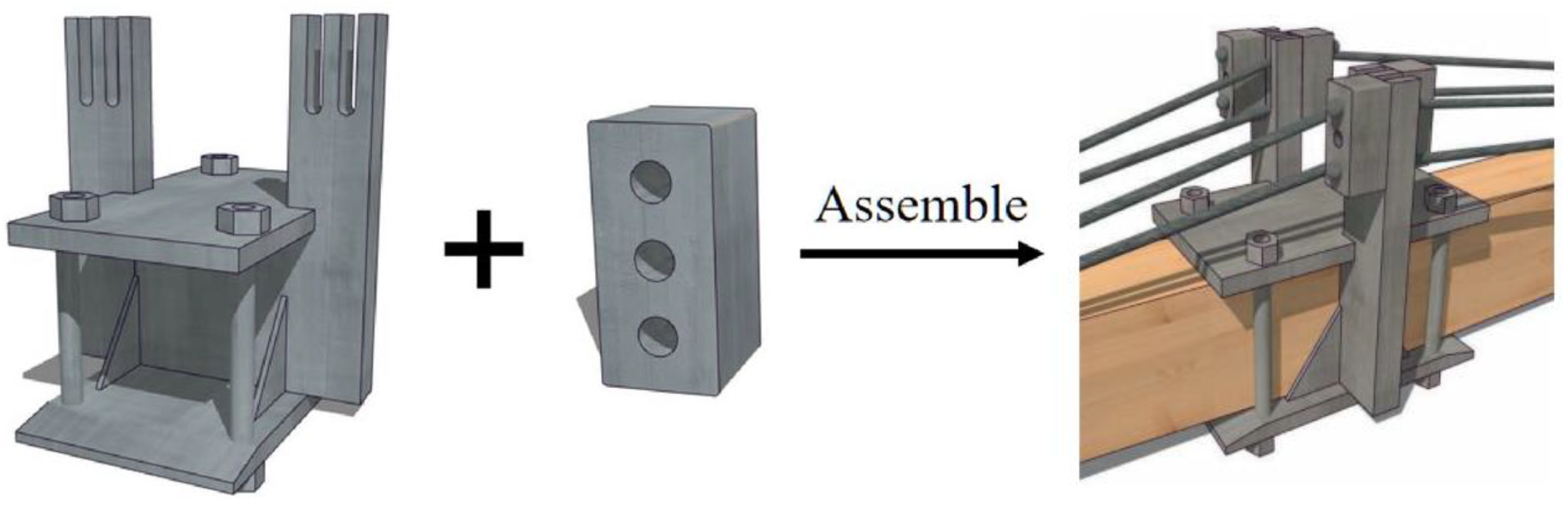
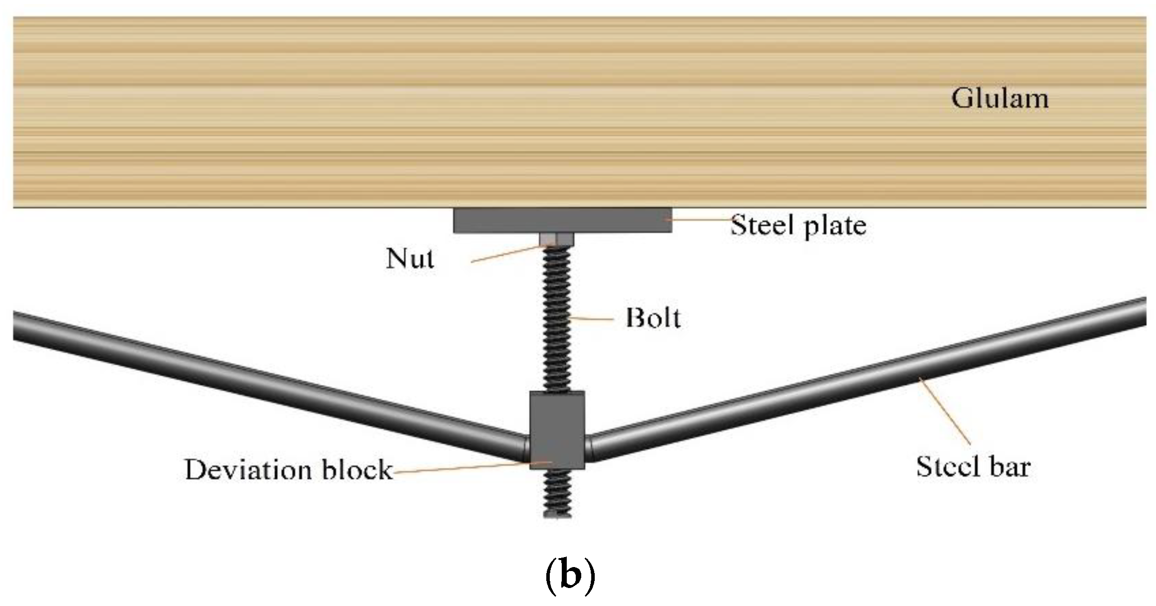
2.1. Prestressing System

The prestressed continuous glulam beams were composed of glulam beams and the prestressed application system, and the system contained anchorage, prestressed installation, the connection device, and prestressed steel wires, as shown in Figure 1. Firstly, the single-span glulam beam was placed in the groove formed by the middle bearing connection device, and then steel wires were put into the groove of the screw steering block and the steering bearing member. Lastly, the anchor was put into the groove of the beam end, respectively, and the prestressed glulam continuous beam was assembled, as shown in Figure 2a. Before applying the external load, stress could be applied by adjusting the length of the bottom screw, as shown in Figure 2b.
As shown in Figure 3a, the arrangement of the steel wire is consistent with the trend of the bending moment diagram. Therefore, the prestressed glulam continuous beam has a better force effect. As shown in Figure 3b, intercept part of the whole continuous beam and the dashed line represents the position of the neutral axis. Moreover, the length from the center of the deviation to the neutral axis represents the corresponding distance from the unstressed neutral axis.

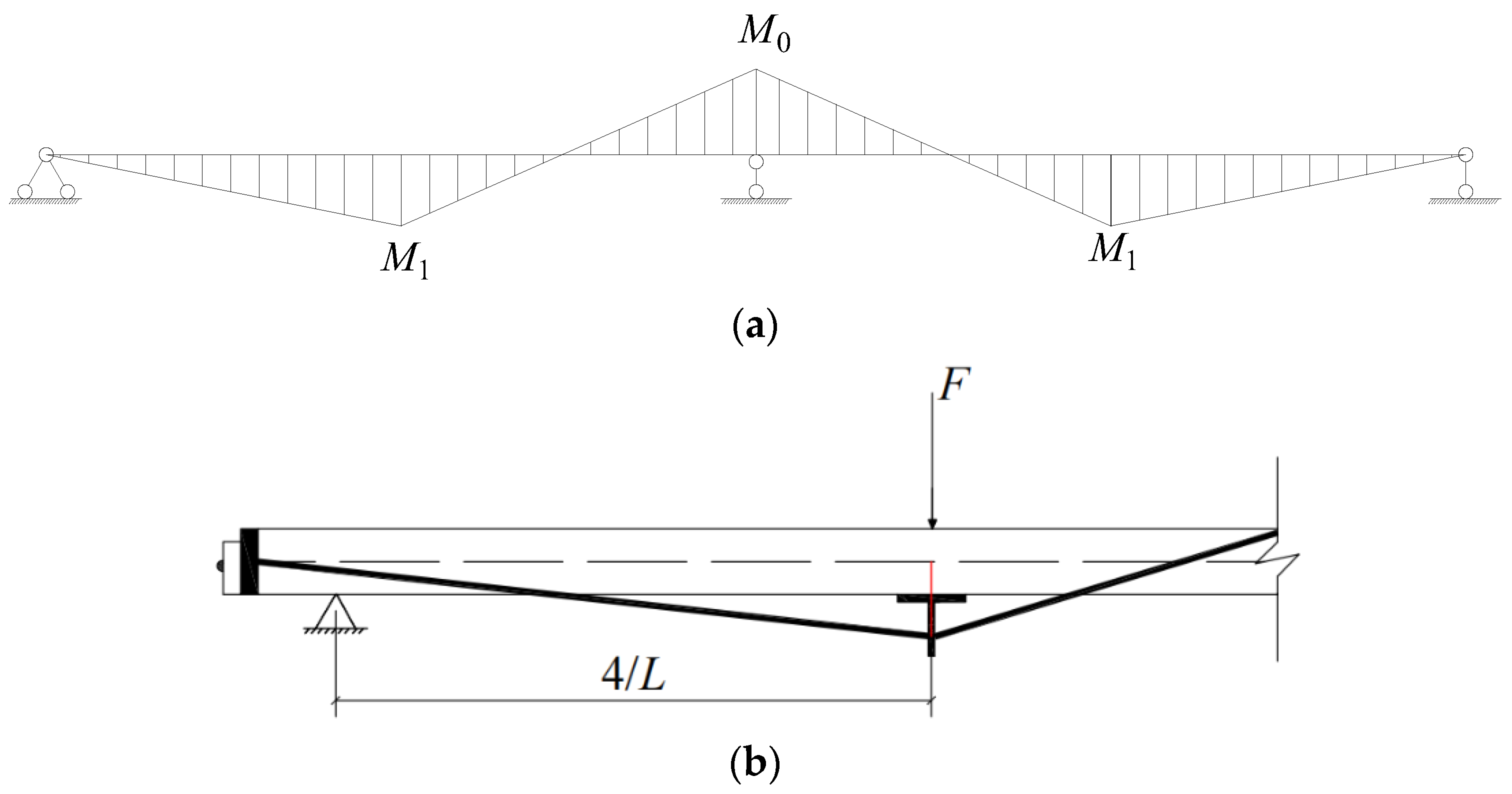
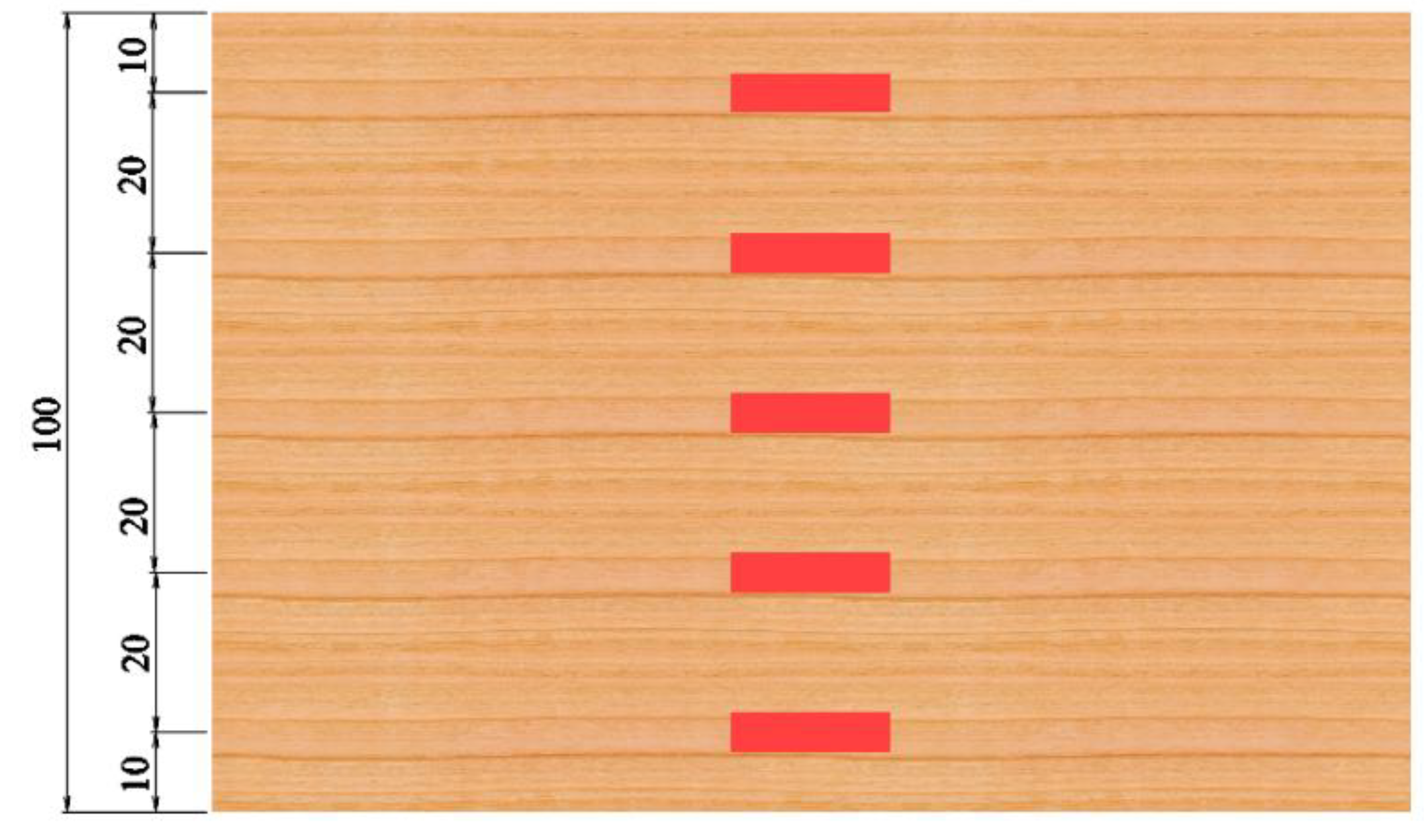
2.2. Specimen Design

In this experiment, the two-span prestressed continuous glulam beam with a geometric scale ratio of 2:1 was selected. The specimen size was 6260 mm × 80 mm × 100 mm (length × width × height), and the mid-span position of the beams was 1500 mm from the center axis of the bearing. The bottom of the beam was the centerline of the screw steering block, and the center side of the beam was the vertical centerline of the strain gauge. The glulam was composed of five layers of 20 mm thick SPF plates, and the prestressed steel wire of grade code 1860 low relaxation prestressed thread steel wire with a diameter of 7 mm was used. Two single-span glulam beams were connected by the connection device and assembled into the prestressed continuous glulam beam, as shown in Figure 4.

2.3. Test Group

In order to investigate the influence of the prestressed value and the number of prestressed steel wires on the bending performance of the prestressed glulam continuous beam after long-term loading, a total of 10 prestressed glulam continuous beams were tested divided into five working conditions, as shown in Table 1.
For convenience, the beam with the long-term test is named long-term beam, and the beam with prestressing regulation after the long-term test is named regulated beam. There were two beams in the same working condition, the first one represented long-term beam, and regulated beam was represented by the other one. For instance, LA1-1 means this beam concluded two prestressed steel wires under prestressed value of 7 kN, and LA1-2 means this beam with prestressing regulation after the long-term test; in other words, the difference between these two beams is whether with prestressing regulation.

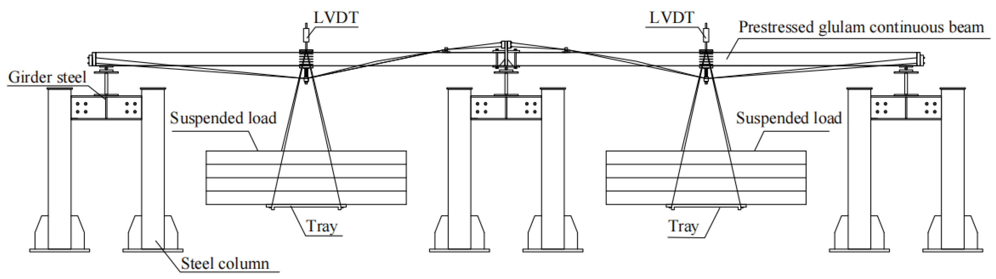
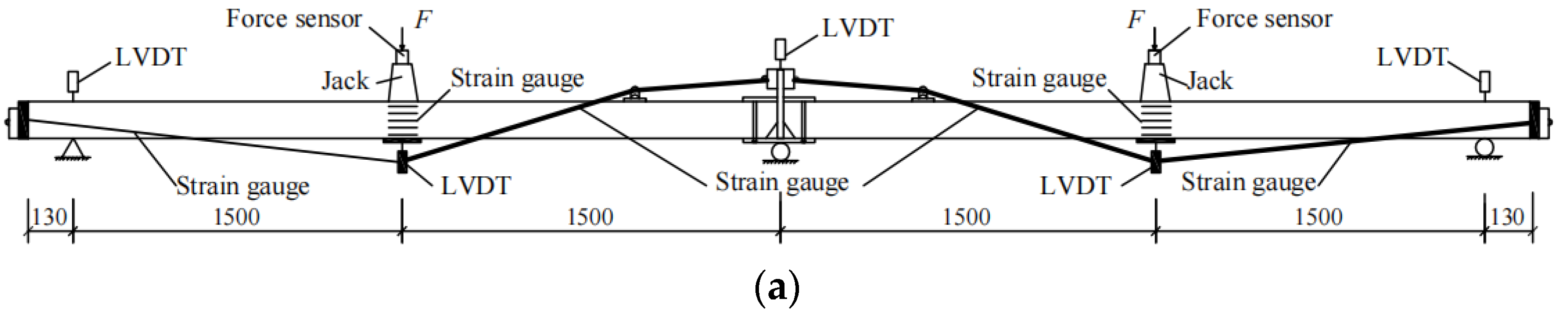
2.4. Loading Scheme and Loading System

Based on the relevant standard [31] and previous research [32], the beams experienced 180 days long-term loading test. Figure 5 shows the long-term loading system. Afterward, those beams experienced the bending experiment, and jacks were used to simultaneously load the left and right two spans of the beam [33,34,35]. The loading schematic diagram of the prestressed glulam continuous beam is shown in Figure 2a. By adopting the loading methods of force control and displacement control, the predicted ultimate load of short-term prestressed glulam continuous beam was 50 kN, and the loading value increased gradually by 10% of 50 kN per stage. After reaching 50% of the predicted ultimate load, 5% of 50 kN per stage was taken as the added value. After loading to 75% of the predicted ultimate load, the loading method was transferred from force control to displacement control. The loading mechanism is shown in Figure 6. The loading value of each stage minus the weight of the jack and force sensor on the test beam.
In order to measure the deformation of test beams, Linear variable differential transformers (LVDTs) were placed at the supports at both ends of the continuous beam and at the midpoint of each beam, and the type of the LVDT was resistive LVDT. In order to monitor the mid-span displacement of the beam and the stress change of the prestressed steel wire during the loading test, five strain gauges were pasted along the height direction at the mid-span position on one side of each beam, as shown in Figure 7. Because the glulam continuous beam was glued by five layers, strain gauges were arranged in the middle of each layer. Moreover, two strain gauges were pasted at the bottom and top of the beam at the same position, respectively. At the same time, strain gauges were adhered after grinding at the corresponding reinforcement of 1/4 beam span. In order to obtain accurate data from the strain gauges during the experimental process, the adhesive tape was used to fix the conductor wire of the strain gauge on the surface of the steel wire. Positions of strain gauges are shown in Figure 8a,b. During the loading process, the displacement changes of the end and mid-span of the beams and the stress value of the prestressed steel wires and the glulam beams were synchronously collected by JM3813 multi-functional static resistance strain measurement system. The acquisition device is shown in Figure 8c.

3. Results and Discussions

To evaluate the effect of creep on the bending performance of the prestress continuous glulam beam, the failure modes of the beams experienced long-term loading and the beams with long-term loading.

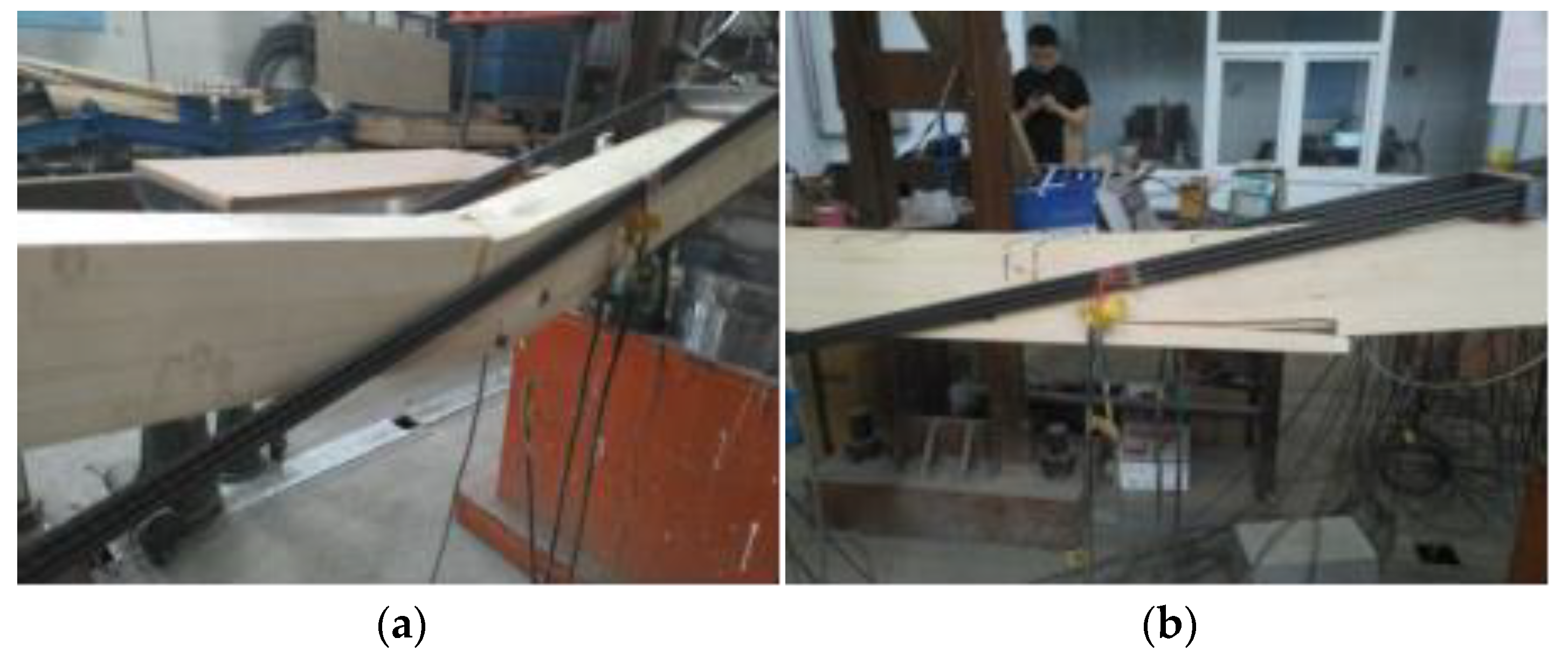
3.1. Failure Modes of Long-Term Beams

After the test, the failure modes of the beams that experienced long-term loading were classified, which can be mainly divided into four types: tensile failure at the beam bottom, compression failure at the beam top, overall instability failure, and tensile failure of steel wire.

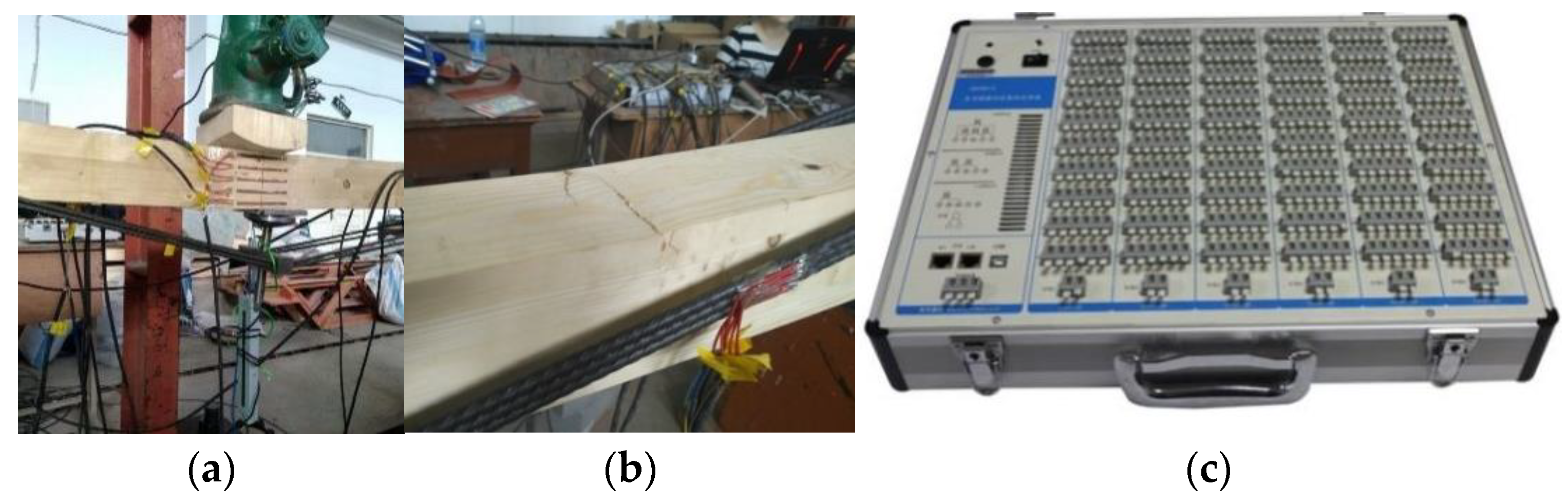
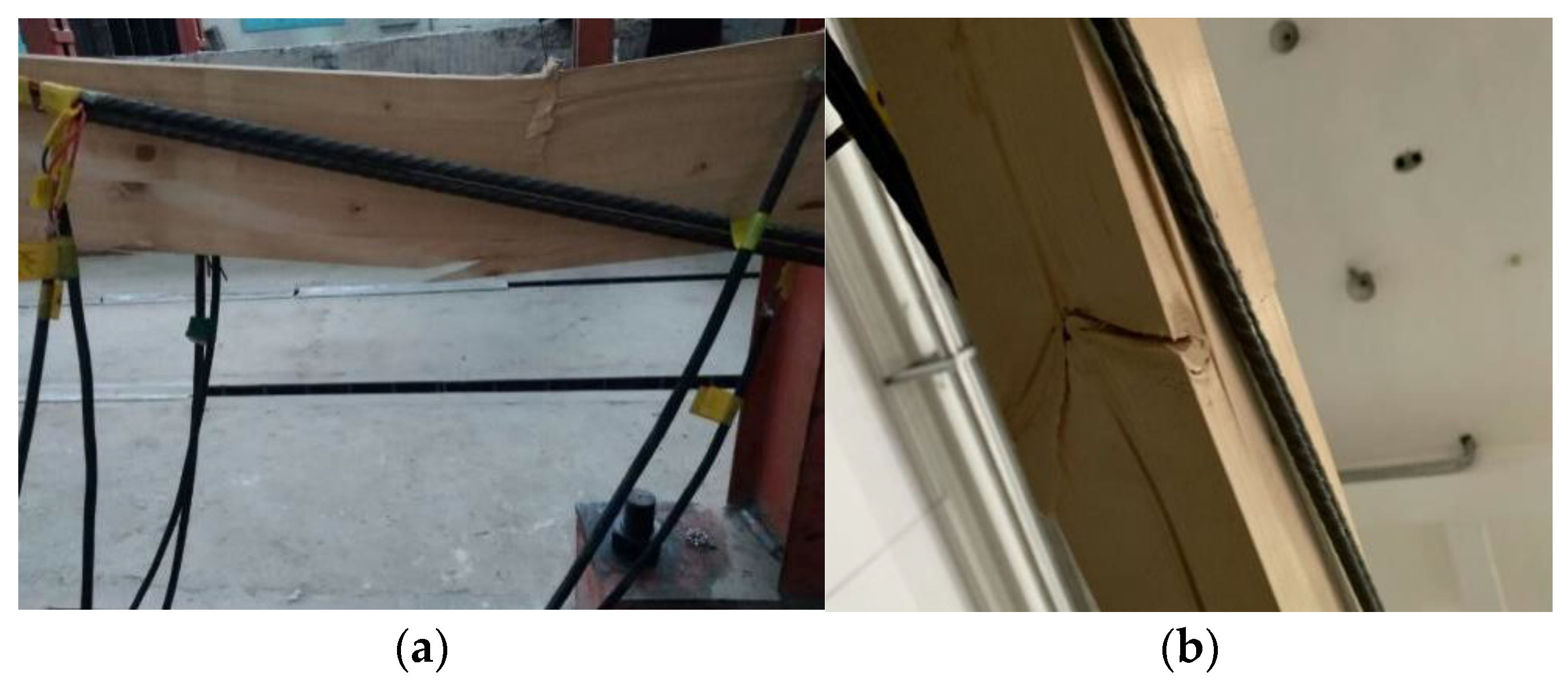
3.1.1. Tensile Failure at the Beam Bottom

The failure at the beam bottom was mainly manifested as: with the increase in load, the mid-span displacement of the continuous beam gradually increased, the top of the beam folded, as shown in Figure 9a, and it continued to extend with the increase in load. Subsequently, slight cracks appeared at the beam bottom. With the increase in the load, the cracks at the beam bottom continued to extend. Finally, tensile failure occurred at the beam bottom at the mid-span or 1/4 beam span near the middle support, as shown in Figure 9b. Meanwhile, loading was stopped.

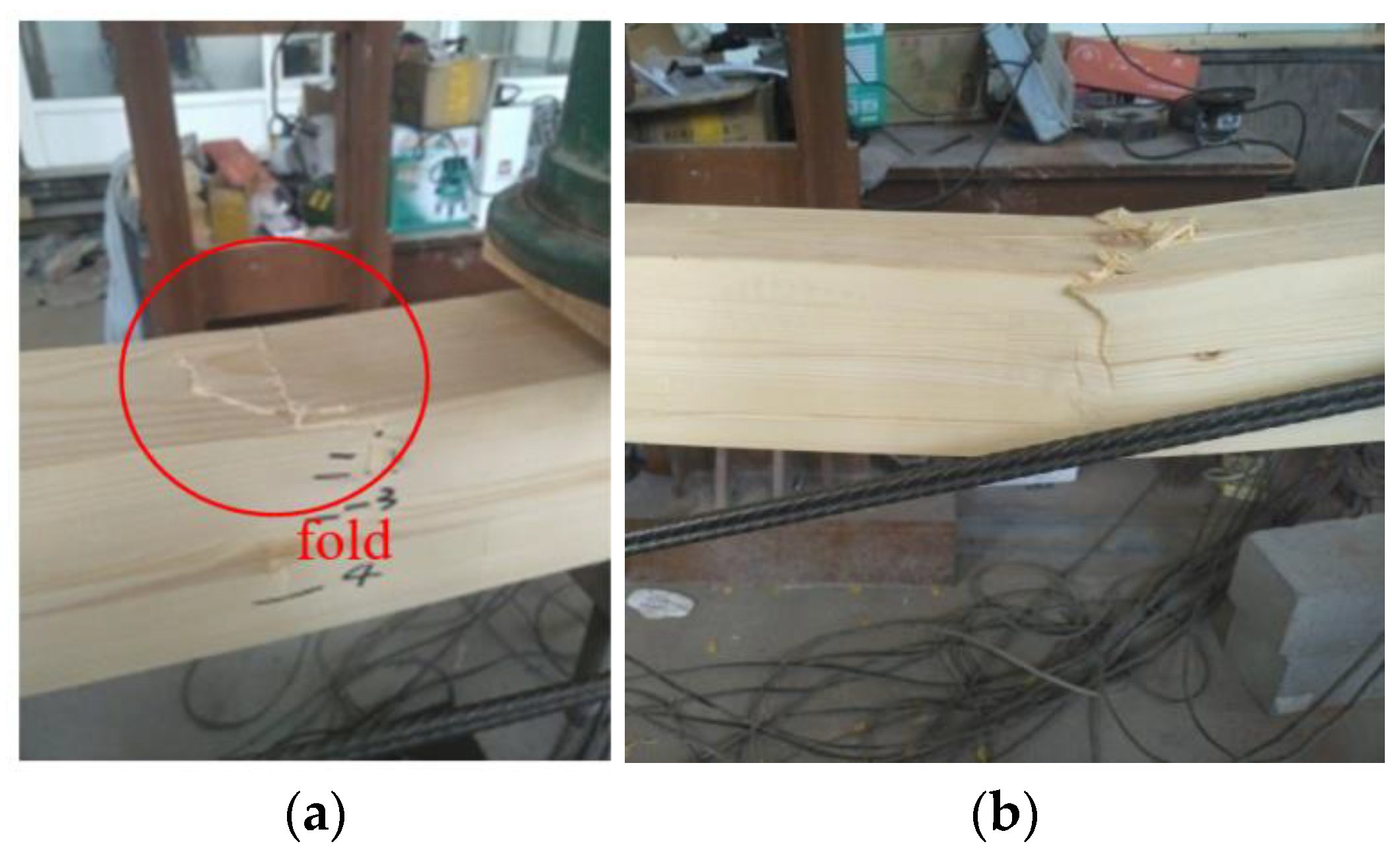
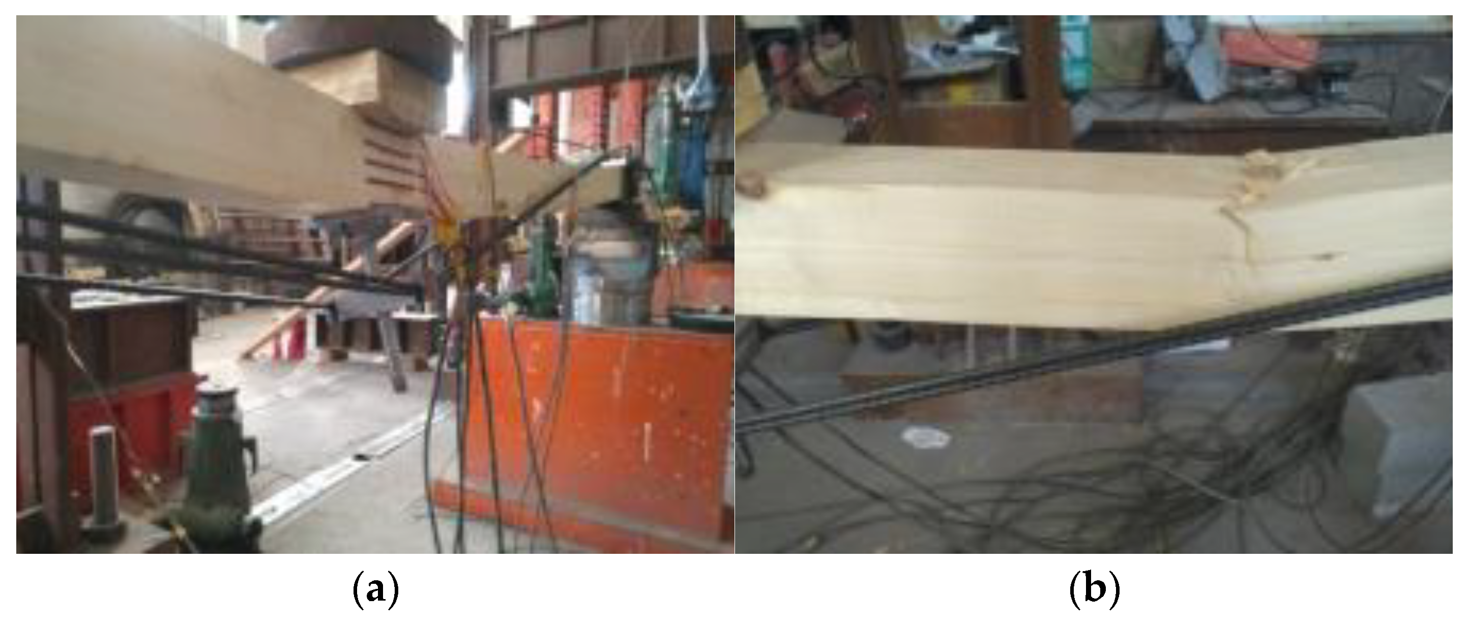
3.1.2. Compressive Failure at the Beam Top

The compressive failure at the beam top was mainly manifested as: with the increase in the load, the displacement of the middle span of the beam increased continuously. Because the top of the beam cannot continue to bear the pressure of the external load, the fold extended in the weak area of the top plate or near the wooden joint. Ultimately, the top of the beam happened to the compressive failure at the middle span or 1/4 span near the middle support, as shown in Figure 10.

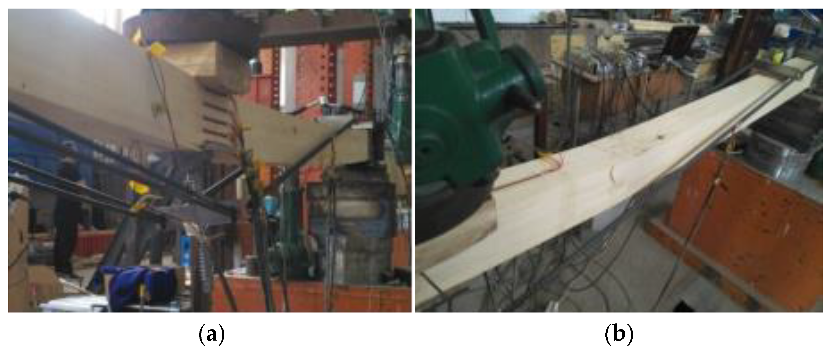
3.1.3. Overall Instability Failure

The overall instability failure is mainly manifested as the mid-span displacement of the beam grew with the increase in load; at the same time, due to the length error of the steel wire, the steel wires bore unequal stress, resulting in screw steering block shift to the side of the prestressed steel wire that produced large stress, and finally, the beam occurred overall instability failure, as shown in Figure 11.

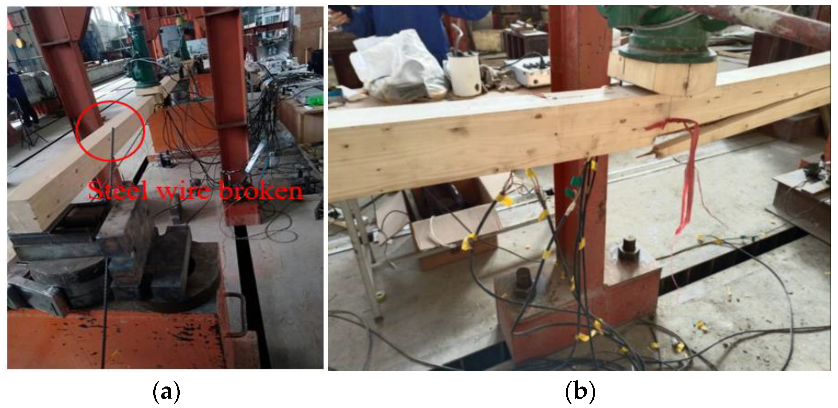
3.1.4. Steel Wire Fracture

The steel wire failure is mainly manifested as: with the increase in load, the displacement of beam span increased; the steel wire could not bear the external load, so it broke at the position of the middle-span screw steering block, as shown in Figure 12a. The glulam part was pulled and damaged at the bottom of the beam after the steel wire broke, as shown in Figure 12b. The reason is that, on the one hand, the steel wire was in a high-stress state due to long-term loading, which reduced its strength; on the other hand, there was a certain stress concentration in the position of the steering block, which leads to the tensile failure of the steel wire. The damage pattern is shown in Figure 12.

3.2. Short-Term Beam Failure Modes

In order to evaluate the effect of creep on the mechanical properties of the continuous beams after long-term loading, the previous results of short-term tests were used for comparative analysis [30]. Based on the previous tests, several representative failure patterns were obtained, as shown in Figure 13, Figure 14, Figure 15, Figure 16 and Figure 17, including tensile failure, compressive failure, and overall stability failure.

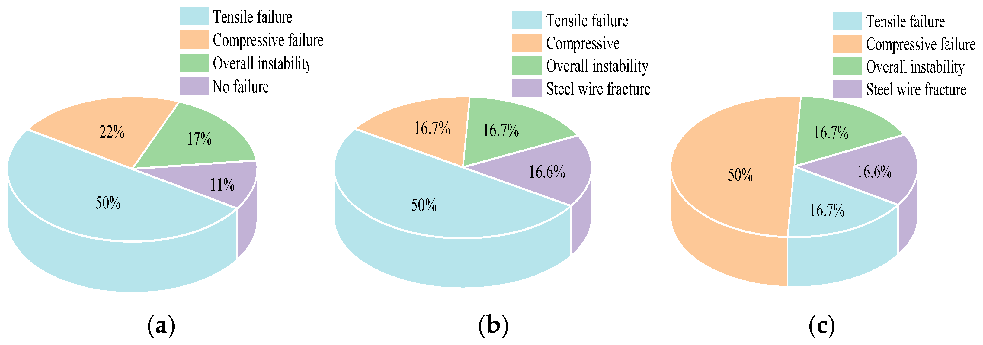
3.3. Classification and Analysis of Beam Failure Modes

The failure modes of long-term beams, regulated beams, and short-term beams were analyzed, as shown in Table 2. Figure 18 shows the probability of occurrence of various failure modes more clearly.
The comparison results in the pie chart show that: on the one hand, there is no phenomenon of steel wire breaking in the failure modes of short-term beams, but it is found in long-term beams and regulated beams, respectively. The reason is that the glulam continuous beams composed of steel wires made the steel wire be in a high-stress state after long-term loading, so its strength is reduced, and the tensile fracture occurs. On the other hand, compared with the long-term beam and short-term beam, the regulated beam appears to have more compression failure. The reason is that the secondary regulation of the regulatory beam after long-term loading increases the tensile zone at the bottom of the beam and moves the neutral axis upward, which is more likely to fold in the compression zone and cause compression failure at the beam top.

4. Analysis and Discuss

4.1. Ultimate Load

To further explore the effects of creep and prestress on the bearing capacity of the test beams under the long-term and the short-term loading, the regulated beam and the short-term beam are compared and analyzed, respectively. The specific information is shown in Table 3 and Table 4 below.
As shown in Table 3, the ultimate load of the prestressed glulam continuous beam after long-term loading decreases compared with that under short-term loading; one reason is that the creep of wood would occur after long-term loading, resulting in long-term deformation of glulam; the other reason is that the creep of wood would result in stress relaxation, which reduces the positive effect of prestressing applied to the beam in the early stage, and increases the tensile stress at the beam bottom, making it more prone to tensile failure. From the results of group A, it can be found that the number of prestressed steel wires increases from two to six under the condition of constant prestressed value, and the ultimate load of long-term beams decreases by 13.5–37.6% compared with short-term beams. It can be found from the results of group B that when the number of prestressed steel wires remains unchanged, the prestressed value increases from 0 to 14 kN, and the ultimate load of long-term beams decreases by 19.9–29.0% compared with short-term beams.
Based on the comparison in Table 4, it can be found that compared with the short-term beam, the ultimate load of the regulating beam is significantly improved. This is because in the regulation process, in order to restore the initial displacement of the beam under load, it is necessary to increase the height of the string to apply greater prestress so as to increase the mid-span internal moment arm of the test beam, thereby greatly improving the bearing capacity of the beam. It can be found from the results of group A that compared with the short-term beam, the number of prestressed steel wires increases from two to six under the same prestressed value, and the ultimate load of the regulated beam increases by 10.7–44.8%. It can be found from the results of group B that compared with the ultimate load of the short-term beam, the prestressed value increases from 0 to 14 kN under the same number of prestressed steel wires, and the ultimate load of the regulated beam increases by 26.9–46.4%.

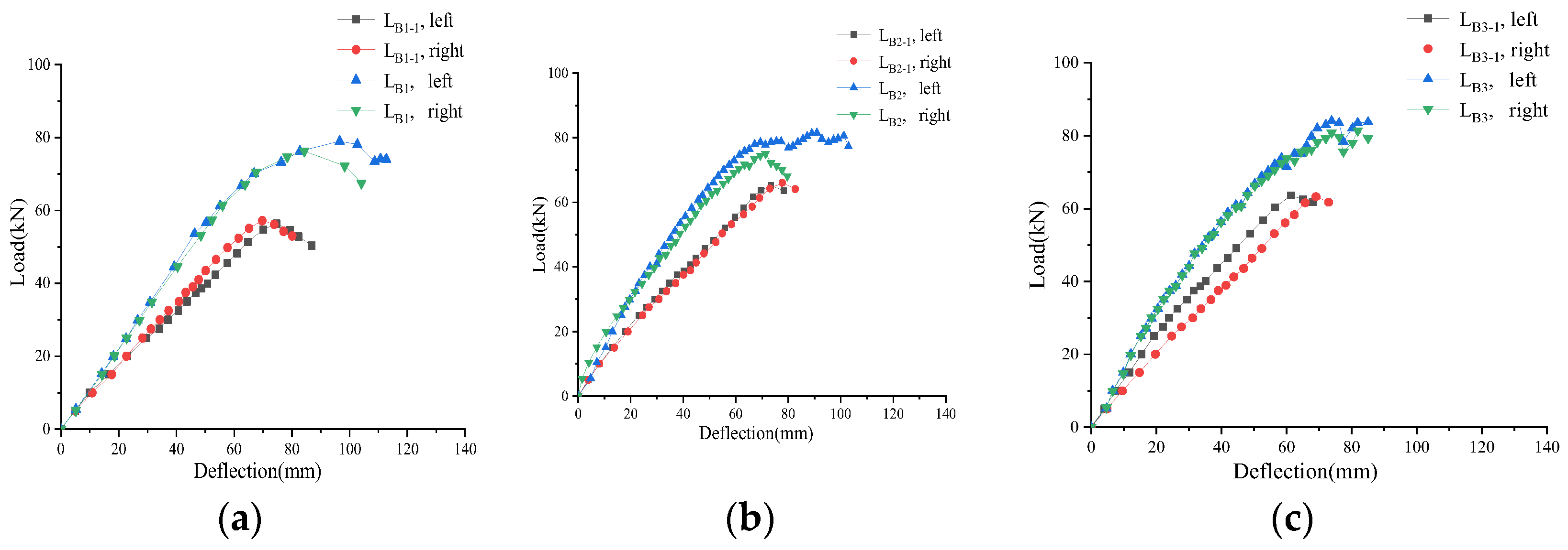
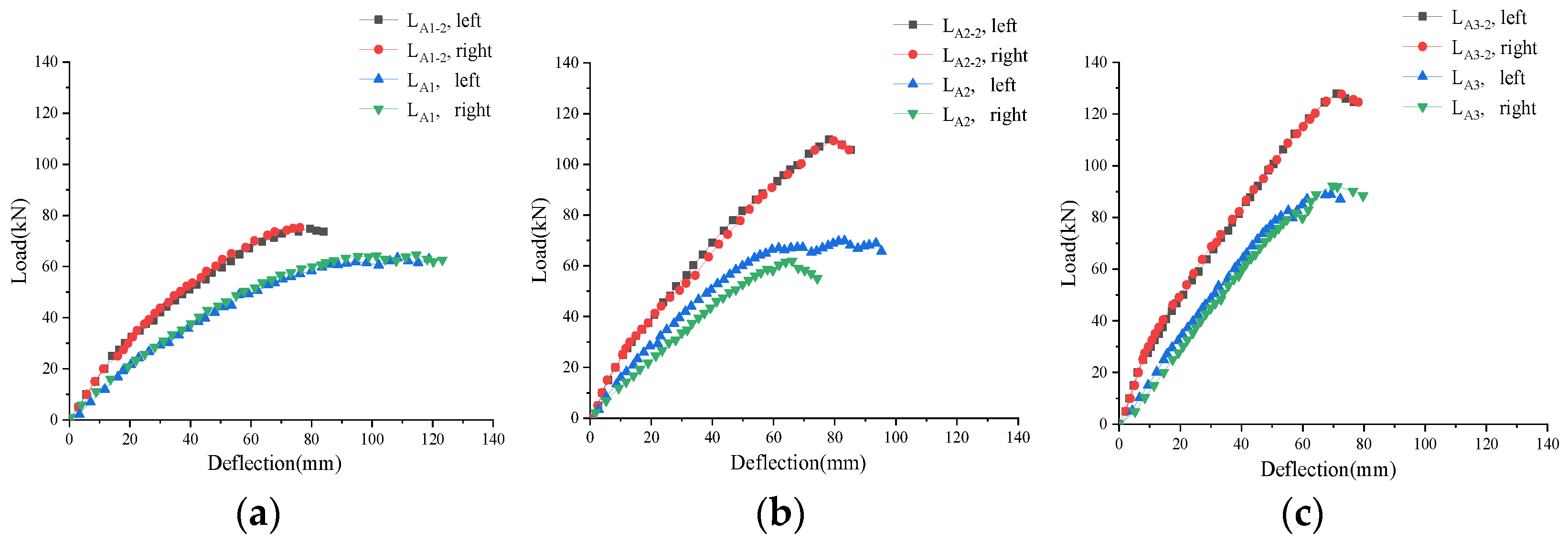
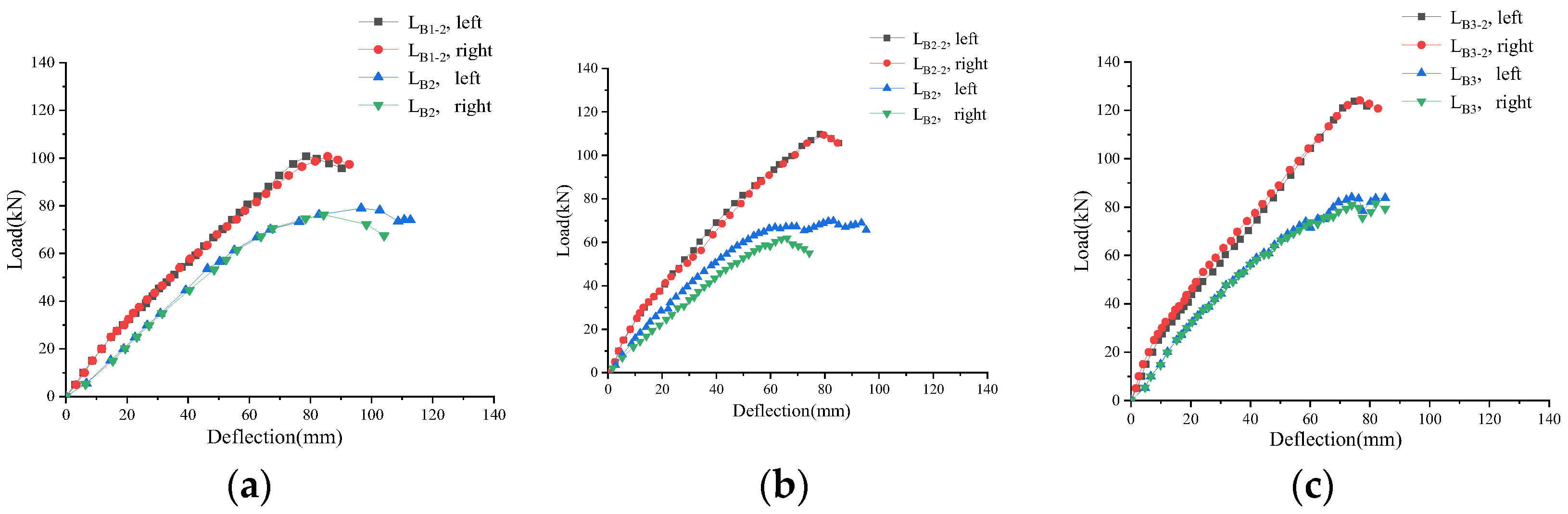
4.2. Load–Displacement Relationships

In order to compare and analyze the load and displacement changes of three kinds of test beams when they are damaged, the load–displacement curves of long-term beams and short-term beams are plotted, as shown in Figure 19 and Figure 20. The load–displacement curve of the regulated beams should have an inverted arch section, but for the convenience of comparison with other beams, the curve also started from zero. Therefore, it is stipulated that the mid-span displacement of the test beam before loading is zero, the displacement is positive downward, and the displacement is negative upward.
As shown in Figure 19, there is no obvious difference between load–displacement curves of the group A test beam and the short-term beam. When the prestressed value is constant, the ultimate deformation of the group A test beam increases with the increase in steel wires, but the stiffness of the beam does not increase significantly.
As shown in Figure 20, when the number of steel wires is constant, with the increase in prestressed value, the load–displacement curve of the group B test beam gradually close to the curve of the short-term beam, indicating the prestressed value can effectively improve the stiffness of the beam. However, the load–displacement curves of group A test beams are below that of short-term beams, indicating that after long-term loading, the test beams reach a high-stress state, and the overall stiffness of the beams decreases. Figure 21 and Figure 22 show the load–displacement curves of the regulated beam and the short-term beam.
As shown in Figure 21, the curve slope of the regulated beam is above the curve of the short-term beam, indicating the prestressed regulation can improve the stiffness of the beam, and the curve slope of the regulating beam increases with the increase in steel wires. By comparing the ultimate deformation of the regulated beam and the short-term beam, the deformation capacity of the regulated beam is slightly weakened, but it can still meet the requirements.
As shown in Figure 22, the curve slope of the regulating beam is larger than that of the short-term beam, indicating the prestressed regulation can improve the stiffness of the beam, and the curve slope of the regulated beam increases with the increase in the prestressed value. By comparing the ultimate deformation of the regulated beam and the short-term beam, the deformation capacity of the regulated beam is slightly weakened, but it can still meet the requirements.

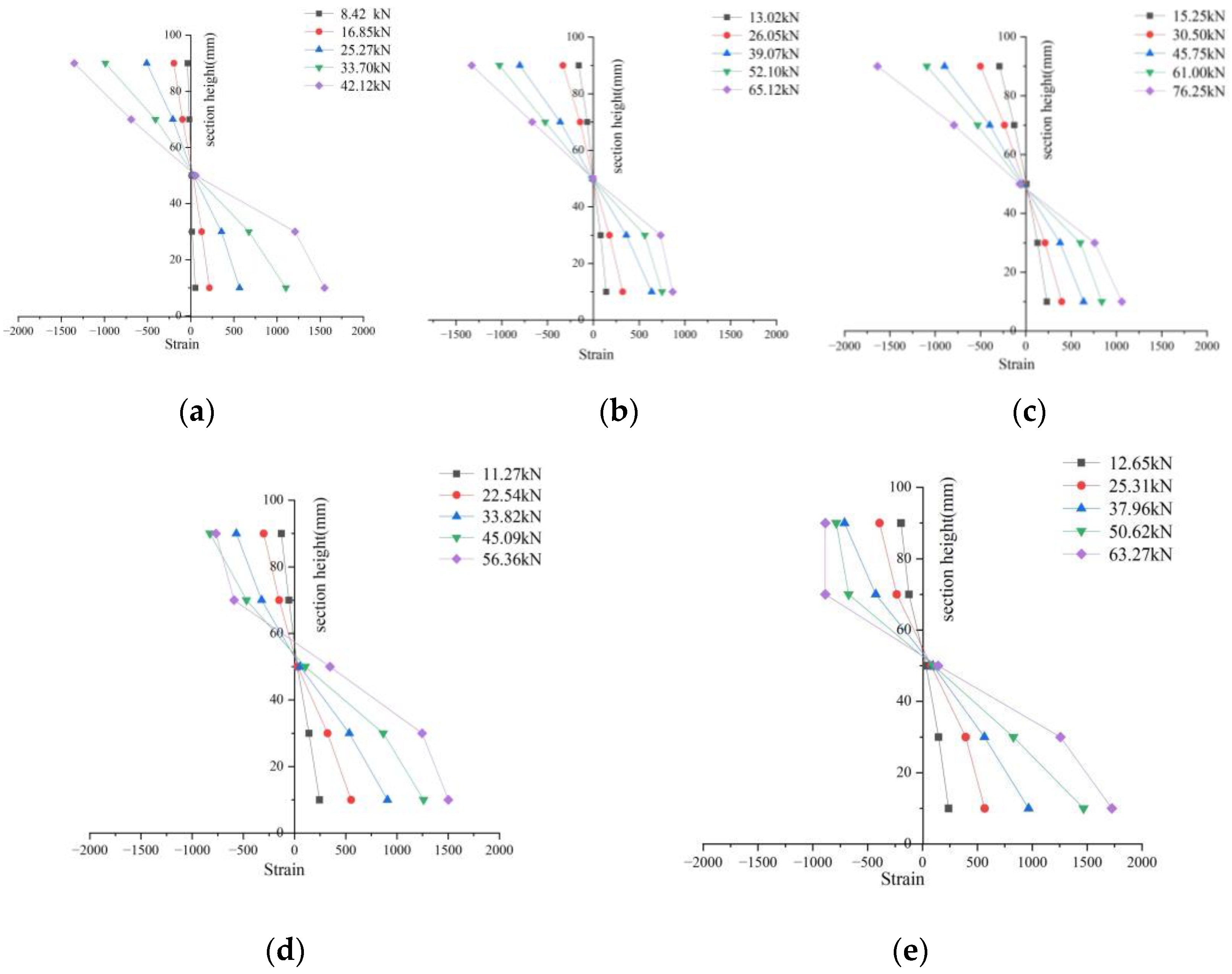
4.3. Cross-Section Strain Distribution

The stress and strain of the mid-span section of the prestressed glulam continuous beam under different working conditions varied under different loading processes. In order to express this change more clearly, a typical span of the continuous beam under different working conditions is selected, and the strain curves of different section heights are shown in Figure 23. Further, 20%, 40%, 60%, 80%, and 100% of the ultimate load of the test beam are selected as the sampling characteristic value. Taking the bottom of the beam as the starting point, the section height of the Y axis is 10 mm, 30 mm, 50 mm, 70 mm, and 90 mm, according to the bonding position of the strain gauge. The intersection point of each curve and the Y axis represents the position of the neutral axis, the negative value of the X axis represents the compression of the glulam, and the positive value represents the tension of the glulam.
As shown in Figure 16, it is obvious to find that the neutral axis moves up; this is because the prestress reduces the compression zone. Moreover, in the process of loading system at all levels, some of the curves have the trend of data reduction because the top plate of glulam produces fold, or the bottom plate cracks, which lead to the decrease in the bearing capacity of the beam and the change of the test data. This phenomenon occurs in the test beams when the load is large, so it can be considered that the height strain curve of the mid-span section of the prestressed glulam continuous beam in this test is basically linear distribution.

5. Conclusions

Glulam, as a promising sustainable material, is used in the construction industry more and more extensively. In this paper, the prestress regulation of the continuous beam after long-term loading was conducted. The conclusions can be obtained as:
(1) The failure modes of the prestressed glulam continuous beam after long-term load could be divided into four types, including the tensile failure, the compression failure, the overall instability failure, and the steel wire fracture.
(2) Compared with the short-term beam, when the prestressed value was constant, the ultimate load of the long-term beam decreased by 3.51–37.65% with the increase in the number of prestressed steel wires; when the number of prestressed steel wires was constant, the ultimate load of long-term beam decreased by 19.86–28.98% with the increase in the prestressed value.
(3) The prestressing regulation can effectively solve the problem of decreasing load capacity due to creep. Compared with the short-term beam, the ultimate load of the regulated beam increased by 10.67–46.41%. Therefore, it can be used in the actual process of prestressing to compensate for tension.
(4) The above contents can be used for reference for the research of prestressed glulam continuous beam. Future research will further explore the influence of creep on the prestressed glulam continuous beam. One of the directions may be to derive the formula. Moreover, it is important to improve the prestressed installation based on existing research.

Author Contributions

Conceptualization, N.G.; methodology, N.G. and Y.Z. (Yan Zhao); software, Y.Z. (Yunan Zhang); validation, L.M.; data curation, Y.Z. (Yunan Zhang); writing—original draft preparation, Y.Z. (Yunan Zhang); writing—review and editing, N.G. and L.M. All authors have read and agreed to the published version of the manuscript.

Funding

The research work presented in this paper is supported by the Innovation Foundation for Doctoral Program of Forestry Engineering of Northeast Forestry University (LYGC202119), the Natural Science Foundation of Fujian Province (2020J01402), and the Nature Science Foundation of Heilongjiang Province (LH2019E005).

Institutional Review Board Statement

Not applicable.

Informed Consent Statement

Not applicable.

Data Availability Statement

The data presented in this study are available on request from the corresponding author.

Conflicts of Interest

The authors declare no conflict of interest.

References

  1. Lam, E. Canadian CLT Handbook, 2019 Edition/Tall Wood Buildings: Design, Construction and Performance. Can. Archit. 2020, 65, 48–49. [Google Scholar]
  2. Li, Z.; Zhou, R.; He, M.; Sun, X. Modern Timber Construction Technology and Engineering Applications in China. Proc. Inst. Civ. Eng.-Civ. Eng. 2019, 172, 17–27. [Google Scholar] [CrossRef]
  3. He, M.J.; Tao, D.; Li, Z. Research Progress of Multistory Wood and Wood Mixed Structure. J. Build. Struct. 2016, 37, 1–9. [Google Scholar]
  4. Schoenwald, S.; Hu, L. Technical Guide for the Design and Construction of Tall Wood Buildings in Canada. In Technical Guide for the Design and Construction of Tall Wood Buildings in Canada; FPInnovations: Pointe Claire, QC, Canada, 2014; pp. 1–29. [Google Scholar]
  5. Issa, C.A.; Kmeid, Z. Advanced Wood Engineering: Glulam Beams. Constr. Build. Mater. 2005, 19, 99–106. [Google Scholar] [CrossRef]
  6. Zhou, S.; Feng, S.; Xiong, G.; Zhu, H. Experimental Study on Bending Properties of Modern Glued Wood Beams. Build. Technol. 2020, 51, 307–310. [Google Scholar]
  7. Zhou, X.; Cao, L.; Zeng, D.; He, C. Flexural Capacity Analysis of Glulam Beams. Build. Struct. 2015, 45, 91–96. [Google Scholar]
  8. Kozinetc, G.; Kärki, T.; Barabanschikov, Y.; Lahtela, V.; Zotov, D. Mechanical Properties of Sustainable Wooden Structures Reinforced with Basalt Fiber Reinforced Polymer. Mag. Civ. Eng. 2020, 100, 10012. [Google Scholar]
  9. Zhang, J.; Shen, H.; Qiu, R.; Xu, Q.; Gao, S. Short-Term Flexural Behavior of Prestressed Glulam Beams Reinforced with Curved Tendons. J. Struct. Eng. 2020, 146, 04020086. [Google Scholar] [CrossRef]
  10. Lindyberg, R.F.; Dagher, H.J. ReLAM: Nonlinear Probabilistic Model for the Analysis of Reinforced Glulam Beams in Bending. J. Struct. Eng. 2012, 138, 777–788. [Google Scholar] [CrossRef]
  11. Glišović, I.; Stevanović, B.; Todorović, M. Flexural Reinforcement of Glulam Beams with CFRP Plates. Mater. Struct. 2016, 49, 2841–2855. [Google Scholar] [CrossRef]
  12. Mei, L.; Guo, N.; Zuo, H.; Li, L.; Li, G. Influence of the Force Arm on the Flexural Performance of Prestressed Glulam Beams. Adv. Civ. Eng. 2021, 2021, 1–16. [Google Scholar] [CrossRef]
  13. Yang, H.; Ju, D.; Liu, W.; Lu, W. Prestressed Glulam Beams Reinforced with CFRP Bars. Constr. Build. Mater. 2016, 109, 73–83. [Google Scholar] [CrossRef] [Green Version]
  14. Silva-Henriquez, R.; Gray, H.; Dagher, H.J.; Davids, W.G.; Nader, J. Strength Performance of Prestressed Glass Fiber-Reinforced Polymer, Glued-Laminated Beams. Forest. Prod. J. 2010, 60, 33–39. [Google Scholar] [CrossRef]
  15. Anshari, B.; Guan, Z.W.; Kitamori, A.; Jung, K.; Komatsu, K. Structural Behaviour of Glued Laminated Timber Beams Pre-Stressed by Compressed Wood. Constr. Build. Mater. 2012, 29, 24–32. [Google Scholar] [CrossRef]
  16. Mcconnell, E.; Mcpolin, D.; Taylor, S. Post-Tensioning of Glulam Timber with Steel Tendons. Constr. Build. Mater. 2014, 73, 426–433. [Google Scholar] [CrossRef] [Green Version]
  17. Mei, L.; Guo, N.; Li, L.; Zuo, H.; Zhao, Y. Study on Flexural Performance of Prestressed Glulam Continuous Beams under Control Influence. J. Wood Sci. 2021, 67, 1–14. [Google Scholar] [CrossRef]
  18. Lu, W.; Liu, W.; Geng, Q.; Yang, H.; Yue, K. Study on Flexural Behavior of Glued Laminated Timber Beams Reinforced with Vertical CFRP Lath Inlay. J. Build. Struct. 2014, 35, 151–157. [Google Scholar]
  19. Guo, N.; Jiang, H.; Zuo, H. The Research on Flexural Behavior Experiment of Prestressed Glue-Lumber Beams after Longterm Loading. Model. Meas. Control. B 2017, 86, 49–62. [Google Scholar] [CrossRef]
  20. Yahyaei-Moayyed, M.; Taheri, F. Creep Response of Glued-Laminated Beam Reinforced with Pre-Stressed Sub-Laminated Composite. Constr. Build. Mater. 2011, 25, 2495–2506. [Google Scholar] [CrossRef]
  21. Lu, W.; Song, E.; Yue, K.; Liu, W. Experimental Study on Creep Behavior of FRP Plate Reinforced Glulam Beams. J. Build. Mater. 2013, 16, 294–297. [Google Scholar]
  22. Hunt, D.G. The Prediction of Long-Time Viscoelastic Creep from Short-Time Data. Wood Sci. Technol. 2004, 38, 479–492. [Google Scholar] [CrossRef]
  23. O’Ceallaigh, C.; Sikora, K.; Mcpolin, D.; Harte, A.M. Modelling the Hygro-Mechanical Creep Behaviour of FRP Reinforced Timber Elements. Constr. Build. Mater. 2020, 259, 119899. [Google Scholar] [CrossRef]
  24. Guo, N.; Xiong, H.; Wu, M.; Zuo, H.; Xin, D. Long-Term Bending Behaviour of Prestressed Glulam Bamboo-Wood Beam Based on Creep Effect. SDHM Struct. Durab. Health Monit. 2020, 14, 229–248. [Google Scholar] [CrossRef]
  25. Davids, W.G.; Dagher, H.J.; Breton, J.M. Modeling Creep Deformations of FRP-Reinforced Glulam Beams. Wood Fiber Sci. 2000, 32, 426–441. [Google Scholar]
  26. Moayyed, M.Y.; Farid, T. Creep Response of Glulam Reinforced by a Novel Pre-Stressed FRP-Wood Composite System. In Proceedings of the 11th World Conference on Timber Engineering 2010, Trentino, Italy, 20–24 June 2010; pp. 601–609. [Google Scholar]
  27. Yahyaei-Moayyed, M.; Taheri, F. Experimental and Computational Investigations into Creep Response of AFRP Reinforced Timber Beams. Compos. Struct. 2010, 93, 616–628. [Google Scholar] [CrossRef]
  28. Roshchina, S.; Lukin, M.; Lisyatnikov, M.; Koscheev, A. The Phenomenon for the Wood Creep in the Reinforced Glued Wooden Structures. MATEC Web Conf. 2018, 245, 03020. [Google Scholar] [CrossRef]
  29. Guo, N.; Wang, H.; Zuo, H. Flexural Experiment on Prestressed Glued Bamboo and Lumber Beam for Material Selection. Rev. Compos. Matériaux 2018, 28, 195–210. [Google Scholar] [CrossRef]
  30. Guo, N.; Wang, W.; Zuo, H. Flexural Property of String Beam of Pre-Stressed Glulam Based on Influence of Regulation and Control. SDHM Struct. Durab. Health Monit. 2019, 13, 143–179. [Google Scholar] [CrossRef]
  31. D6815-09; Standard for Evaluation of Duration of Load and Creep Effects of Wood and Wood-Based Products. Current Edition Approved Dec. 1, 2009. Published February 2010. Originally Approved in 2001. Last Previous Edition Approved in 2001 as D6815-02a. ASTM International: West Conshohocken, PA, USA, 2010.
  32. Chen, B.; Gao, D.; Li, P.; Liu, Y. Experimental Study and Creep Analysis of Long-Term Flexural Behavior of Recombined Bamboo Beams. Sichuan Archit. Sci. Res. Inst. 2020, 46, 50–56. [Google Scholar]
  33. ICS 91.010.30; Technical Aspects. ISO: Geneva, Switzerland. Available online: https://www.iso.org/ics/91.010.30/x/ (accessed on 15 May 2022).
  34. ICS 91.080.20; Timber Structures. ISO: Geneva, Switzerland. Available online: https://www.iso.org/ics/91.080.20/x/ (accessed on 15 May 2022).
  35. Eurocode 5 Part 1,1-DDENV 1995-1-1, Eurocode 5: Design of timber structures—Part 1-1: General-Common Rules and Rules for Buildings. European standards: Pilsen. Czech Republic or. Available online: https://www.phd.eng.br/wp-content/uploads/2015/12/en.1995.1.1.2004.pdf (accessed on 15 May 2022).
Figure 1. The connection device diagram.
Buildings 12 00895 g001
Figure 2. Schematic diagram of specimen. (a) Schematic diagram of glulam continuous beam; (b) Schematic diagram of prestressed apparatus.
Buildings 12 00895 g002aBuildings 12 00895 g002b
Figure 3. Moment distribution diagram. (a) Moment diagram of glulam continuous beam; (b) The corresponding distances from the unstressed neutral axis.
Buildings 12 00895 g003
Figure 4. Prestressed glulam continuous beam.
Buildings 12 00895 g004
Figure 5. Long-term loading schematic.
Buildings 12 00895 g005
Figure 6. Diagram of the loading mechanism.
Buildings 12 00895 g006
Figure 7. The location of the strain gauges.
Buildings 12 00895 g007
Figure 8. Strain Gauge Layout and Data Acquisition Device. (a) The strain gauge layout of glulam; (b) Layout diagram of steel strain gauge; (c) JM3813 Static Strain Testing and Analysis System.
Buildings 12 00895 g008
Figure 9. Tensile failure at the beam bottom. (a) Fold extension; (b) Fracture of the bottom plate.
Buildings 12 00895 g009
Figure 10. Compressive failure at the beam top. (a) the fold at midspan; (b) the fold at 1/4 beam.
Buildings 12 00895 g010
Figure 11. Overall instability failure. (a) Overall instability; (b) Instability position.
Buildings 12 00895 g011
Figure 12. Fracture of steel wire. (a) Wire breaking; (b) Beam bottom tearing.
Buildings 12 00895 g012
Figure 13. Failure mode of LA1. (a) Tensile failure of left span; (b) Tensile failure of right span.
Buildings 12 00895 g013
Figure 14. Failure mode of LB1. (a) Overall instability of left span; (b) Compressive failure of right span.
Buildings 12 00895 g014
Figure 15. Failure mode of LA2. (a) Overall instability of left span; (b) Compressive failure of right span.
Buildings 12 00895 g015
Figure 16. Failure mode of LA3. (a) Tensile failure of left span; (b) Tensile failure of right span.
Buildings 12 00895 g016
Figure 17. Failure mode of LB3. (a) Initial fracture of right span; (b) Tensile failure of right span.
Buildings 12 00895 g017
Figure 18. The failure mode of continuous beam. (a) short-term beams; (b) long-term beams; (c) regulated beams.
Buildings 12 00895 g018
Figure 19. Load-displacement curve of group A (long-term beam). (a) 7 kN, 2 steel wires; (b) 7 kN, 4 steel wires; (c) 7 kN, 6 steel wires.
Buildings 12 00895 g019
Figure 20. Load-displacement curve of group B (long-term beam). (a) 0 kN, 4 steel wires; (b) 7 kN, 4 steel wires; (c) 14 kN, 4 steel wires.
Buildings 12 00895 g020
Figure 21. Load-displacement curve of group A (regulated beam). (a) 7 kN, 2 steel wires; (b) 7 kN, 4 steel wires; (c) 7 kN, 6 steel wires.
Buildings 12 00895 g021
Figure 22. Load-displacement curve of group B (regulated beam). (a) 0 kN, 4 steel wires; (b) 7 kN, 4 steel wires; (c) 14 kN, 4 steel wires.
Buildings 12 00895 g022
Figure 23. Strain curves of single-span section of beams under various working conditions. (a) beam LA1; (b) beam LA2/LB2; (c) beam LA3; (d) beam LB1; (e) beam LB3.
Buildings 12 00895 g023
Table 1. Grouping information of test components.
Group AGroup B
BeamNumber of Prestressed Steel Wires (Roots)Prestressed Value (kN)BeamNumber of Prestressed Steel Wires (Roots)Prestressed Value (kN)
LA1-127LB1-140
LA1-2LB1-2
LA2-1 *4LB2-1 *7
LA2-2 *LB2-2 *
LA3-16LB3-114
LA3-2LB3-2
* Note: In the table, the test parameters and variables of the beams LA2-1 and LB2-1, LA2-2 and LB2-2 were the same, so the beam was shared.
Table 2. Failure mode of glulam continuous beam.
GroupingBeamLeft SpanRight Span
Short-term beamLA1II
LB1IIIII
LA2/LB2IIIII
LA3II
LB3(-)I
Long-term beamLA1-1IV(-)
LB1-1(-)III
LA2-1/LB2-1I(-)
LA3-1(-)II
LB3-1(-)I
Regulated beamLA1-2IVI
LB1-2(-)III
LA2-2/LB2-2(-)II
LA3-2II
LB3-2III
Note: Failure mode I is the tensile failure at the beam bottom; failure mode II is the compressive failure at the beam top; failure mode III is the overall instability; failure mode IV is the steel wire fracture.
Table 3. The comparison information of ultimate load between long-term beam and short-term beam.
GroupingBeamPrestressed Value (kN)Number of Steel Wire (Root)Ultimate Load (kN)Change in Carrying Capacity (%)
Group ALA1-17242.12−37.6
LA167.55
LA2-1465.12−19.9
LA281.26
LA3-1676.25−13.5
LA388.16
Group BLB1-10456.36−29.0
LB179.36
LB2-1765.12−19.9
LB281.26
LB3-11463.27−25.1
LB384.51
Note: (1) The beam LA1, LA2, LA3, LB1, LB2, LB3 are short-term beams. The test results were obtained from the short-term test of prestressed glulam continuous beam. The test parameters of beam LA2 and beam LB2 are the same, which is a kind of working condition. Therefore, a beam is shared. (2) The change of carrying capacity is defined as the percentage of bearing capacity reduction between long-term beam and short-term beam = (long-term beam bearing capacity-short-term bearing capacity under the same conditions)/short-term beam bearing capacity × 100%.
Table 4. The comparison information of ultimate load between regulated beam and short-term beam.
GroupingBeamPrestress Value (kN)Number of Steel Wire (Root)Ultimate Load (kN)Change in Carrying Capacity (%)
Group ALA1-27274.7610.7
LA167.55
LA2-24109.3534.6
LA281.26
LA3-26127.6544.8
LA388.16
Group BLB1-204100.6926.9
LB179.36
LB2-27109.3534.6
LB281.26
LB3-214123.7346.4
LB384.51
Note: (1) The change of carrying capacity (%) is defined as the percentage of the increase in the bearing capacity of the regulated beam compared with the short-term beam = (the bearing capacity of the regulated beam-the bearing capacity of the short-term beam under the same working condition)/the bearing capacity of the short-term beam × 100%.
Publisher’s Note: MDPI stays neutral with regard to jurisdictional claims in published maps and institutional affiliations.

