Article

Prestress Self-Equilibrium Force-Finding Method for Cable-Supported Grid Structures Considering Zero-Stress State Form-Finding and the Construction Process

1
Key Laboratory of Concrete and Prestressed Concrete Structures of Ministry of Education, School of Civil Engineering, Southeast University, Nanjing 211189, China
2
National Prestress Engineering Research Center, School of Civil Engineering, Southeast University, Nanjing 211189, China
3
National East China Architectural Design & Research Institute Co., Ltd., Shanghai 200041, China
*
Author to whom correspondence should be addressed.
Buildings 2022, 12(6), 749; https://doi.org/10.3390/buildings12060749
Submission received: 3 May 2022 / Revised: 27 May 2022 / Accepted: 29 May 2022 / Published: 31 May 2022
(This article belongs to the Section Building Structures)

Abstract

:
The cable-supported grid structure (CSGS) is a hybrid structure combined with rigidity and flexibility. Its formed state is closely related to the zero-stress state, construction process, and prestress distribution. The prestress self-equilibrium force-finding method is proposed in this paper to continuously conduct zero-stress state form-finding, the construction process, and prestress state force-finding analysis. As the first engineering project adapting CSGS with an internal compression ring, Shanghai Pudong Football Stadium was taken as the analysis object. The structural finite element model was established in ANSYS, structural components were divided into prestress and ordinary components to form a prestress self-equilibrium system, and the equivalent temperature difference was applied to the prestress components as prestress. The Newton–Raphson method was used for geometric nonlinear analysis. The analysis results show that the internal forces and displacements of the formed structure are consistent with the design state, which proves the validity of the method and provides significant guidance for the actual construction. The method proposed in this paper can effectively and accurately obtain the zero-stress state configuration, structural response during construction, and the prestress distribution after forming in a single analysis, without analyzing the above three separately, which improves the analysis efficiency.

1. Introduction

Cable-supported grid structure (CSGS) is an emerging structure that combines rigidity and flexibility, similar to the suspendome [1,2]. The difference between them is that CSGS generally has an opening in the center of the structure. It is composed of the upper rigid grid, providing rigid support and reducing the flexibility [3], and the lower cable-strut system, which effectively increases the structural span and takes full advantage of material strength [4]. CSGS can obtain the geometric stiffness and the bearing capacity by applying the prestress in the cables, which is identical to other flexible structures. There is a compression ring in the upper rigid grid to supply constraints. The compression ring in CSGS can be assigned to three categories in accordance with its position: external compression ring, internal compression ring, and upper grid as a whole as a compression ring, as shown in Figure 1. Due to its tremendous advantages of light weight, good aesthetic, large-span high bearing efficiency, and good economy, CSGS has gradually aroused widespread attention in the engineering field, especially in the applications of the stadium [5,6]. In comparison, few projects adapt CSGS with an internal compression ring.
In contrast to rigid structures, the configuration of CSGS changes significantly during the construction process. Structural configuration is unstable and dynamic in the construction stage until the design configuration is reached [7]. For CSGS, it is important to find equilibrium configuration and feasible prestress distribution [8,9]. Therefore, it is an essential issue to find a stable self-equilibrium configuration in the design of various structures, including cable-net structures [10,11,12], cable-membrane structures [13,14,15,16], tensegrities [17,18,19,20,21], compressive structures [22], suspension bridges [23,24], and even submerged floating tunnels [25]. As a consequence, form-finding is a research hotspot and has been intensively studied by many scholars. The form-finding methods can be classified into two types: physical hanging models and numerical form-finding methods. The physical hanging model is used to establish a physical model to determine the structural equilibrium state under external loads [26]. Among numerous numerical form-finding methods, the force density method, dynamic relaxation method, and nonlinear finite element method are preponderant. The force density method, first put forward by Linkwitz and Scheck [27,28], defined the ratio of the internal force of components to its corresponding length as the force density, linearizing the nonlinear equations, which is concise and effective. Later researchers also devoted considerable efforts to the force density method [10,29,30]. The dynamic relaxation method transforms a nonlinear static problem into a pseudodynamic one [22] with fictitious mass and damping to calculate the structural equilibrium state, which is proposed by Otter [31] and Day [32]. Barnes [33] introduced the dynamic relaxation method into the form-finding analysis of cable-net and membrane structures. The nonlinear finite element method [34] applies the finite element method [35,36] to nonlinear form-finding analysis and solves nonlinear equations by iteration [37]. In addition to the three numerical methods mentioned above, the evolutionary and intelligent form-finding method has been developed to seek specific equilibrium configurations, genetic algorithms [38,39], group theory [40], particle swarm optimization algorithms [41,42], and the Monte Carlo method [43].
The configuration of CSGS can be defined as the following three states: the zero-stress state is the state before applying prestress where the structure is lofted; the prestress state, also known as the initial state, is the self-equilibrium state under its self-weight and prestress [44]; the load state refers to the state in which external loads are applied to the structure in the prestress state. The above form-finding methods generally only pay attention to the equilibrium configuration in the prestress state. Nevertheless, it is indispensable to determine the zero-stress state in practical engineering and the basis and starting point for subsequent construction steps, which will profoundly impact on the prestress state and the load state. If the prestress state is improperly taken as the starting point of the forming process, the formed structure will deviate from the design requirements, i.e., the configuration “drift” phenomenon [13]. The “drift” has less influence on small-scale structures with a low prestress level. However, it cannot be neglected and is inevitable to solve this problem for large-scale structures with a high prestress level and high precision requirements [45]. Structural components should be processed and assembled in accordance with the configuration of the zero-stress state.
In actual projects, the desired structural configuration is determined by architects or clients in general [21]. Prestress distribution in the desired structural configuration still needs further discussion in theory. Consequently, form-finding problems turn into force-finding problems when the shapes are given in advance [40], because “force” interacts with “form”. Pellegrino and Calladine [46,47,48] proposed the singular value decomposition (SVD) technique to obtain the self-stress modes of cable-strut structures. Yuan and Dong [49] introduce the state of integral feasible prestress to the optimal prestress design. Then, Yuan [50] proposed a general method, referred to as the double singular value decomposition (DSVD), to determine the prestress modes of cable domes. Chen and Dong [9] obtain multioverall self-stress modes from the equilibrium matrix with SVD. Many scholars have also carried out further research on force-finding [20,39,40,51].
The forming process of CSGS is also called the construction process. The construction process is the bridge between the zero-stress state and the prestress state [21]. Valid and rational construction techniques can guarantee the accuracy of prestress distribution and configuration of the formed structure [52]. The structural state of CSGS during the construction process, where the structural configuration and internal force are constantly changing, could be strikingly different from that in the service stage [3]. Hence, it is considerable to track the structural state during the construction process so as to ensure structural safety, which sets higher requirements for form-finding and force-finding in the construction stage. Construction analysis can be divided as follows: direct analysis is to analyze structural displacement and internal force during the construction process in conformity to the actual construction sequence [53]; inverse analysis takes the prestress state as the construction starting point and removes the components step by step to obtain the structural behavior in the construction stage [54]. Moreover, Luo [55] proposed the nonlinear dynamic finite element method to solve form-finding problems of the cable-strut system during the construction process. The ideal control parameters of each construction step can be determined by analysis to adjust the structural state so that the formed state is consistent with the design state.
From the above, it can be seen that zero-stress state form-finding, construction analysis, and prestress state force-finding are a continuous and progressive process. However, relevant research on these three problems is usually conducted independently. Developing an integrated approach to figure out these three problems is the incentive of this work. Therefore, the prestress self-equilibrium force-finding method (PSEFF) considering zero-stress state form-finding and the construction process is proposed. The procedure of the method is to establish the structural analysis model, then perform zero-stress form-finding and construction process analysis in sequence, and update the prestress distribution until the convergence condition is satisfied. The Newton–Raphson iteration method is used for geometric nonlinear analysis. The zero-stress state, structural response during the construction process, and prestress distribution can be obtained through one analysis. The method is employed for zero-stress state form-finding, construction process analysis, and prestress state force-finding for Shanghai Pudong Stadium, which adopts the CSGS with an internal compression ring. The results show that the method is favorable for the construction scheme and proven to be viable and effective.
The remainder of this paper is organized as follows. In Section 2, the analyzed structure, Shanghai Pudong Stadium, is introduced. In Section 3, the basic theory and procedure of the method are elaborated. To demonstrate the validity and precision of the method, analysis of the analyzed structure is conducted in Section 4. Section 5 summarizes the conclusions of this study.

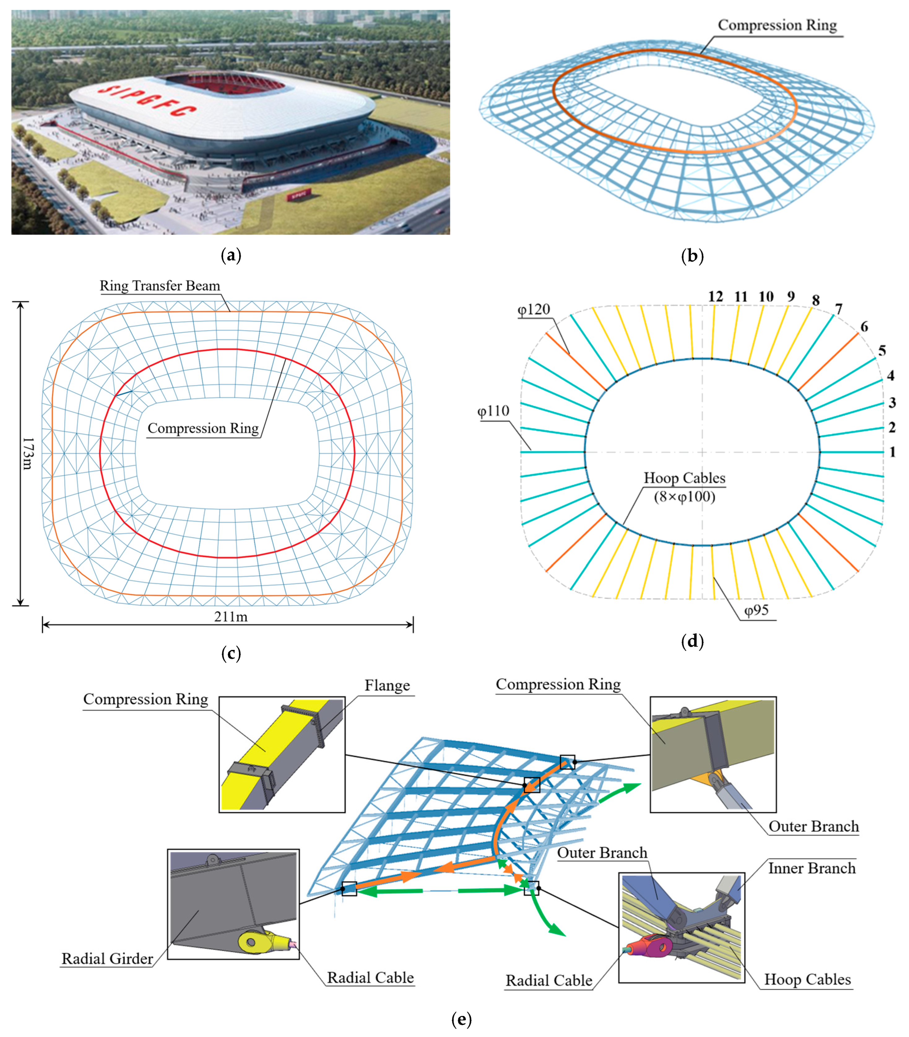
2. Engineering Background

Pudong Football Stadium is the world’s first engineering application of a large-span CSGS with an internal compression ring. It is located in Shanghai, China, with a total construction area of 13,500 m2 and a 33,000 seat capacity. The structural plane is a rounded rectangle, and there are straight lines on the boundary. The long axis of the stadium is 211 m and the short axis is 173 m, as shown in Figure 2. The roof structure is about 11.8 m in height. There are 46 radial cables in total, of which the diameter of the radial cables at the corner is 110 mm and 120 mm, and those on the long side and short side are 95 mm and 110 m, respectively. The hoop cables are arranged in parallel with eight cables with a diameter of 100 mm. As a combination of rigid and flexible structures, CSGS is shaped by tensioning the lower radial cables so that it has the ability to bear loads itself. The primary constituent unit of the structure is composed of radial cable, radial girder, internal compression ring, V column outer branch, and hoop cables, forming the prestress self-balancing triangle area, as shown in Figure 2e. The specifications of the main steel components are listed in Table 1.

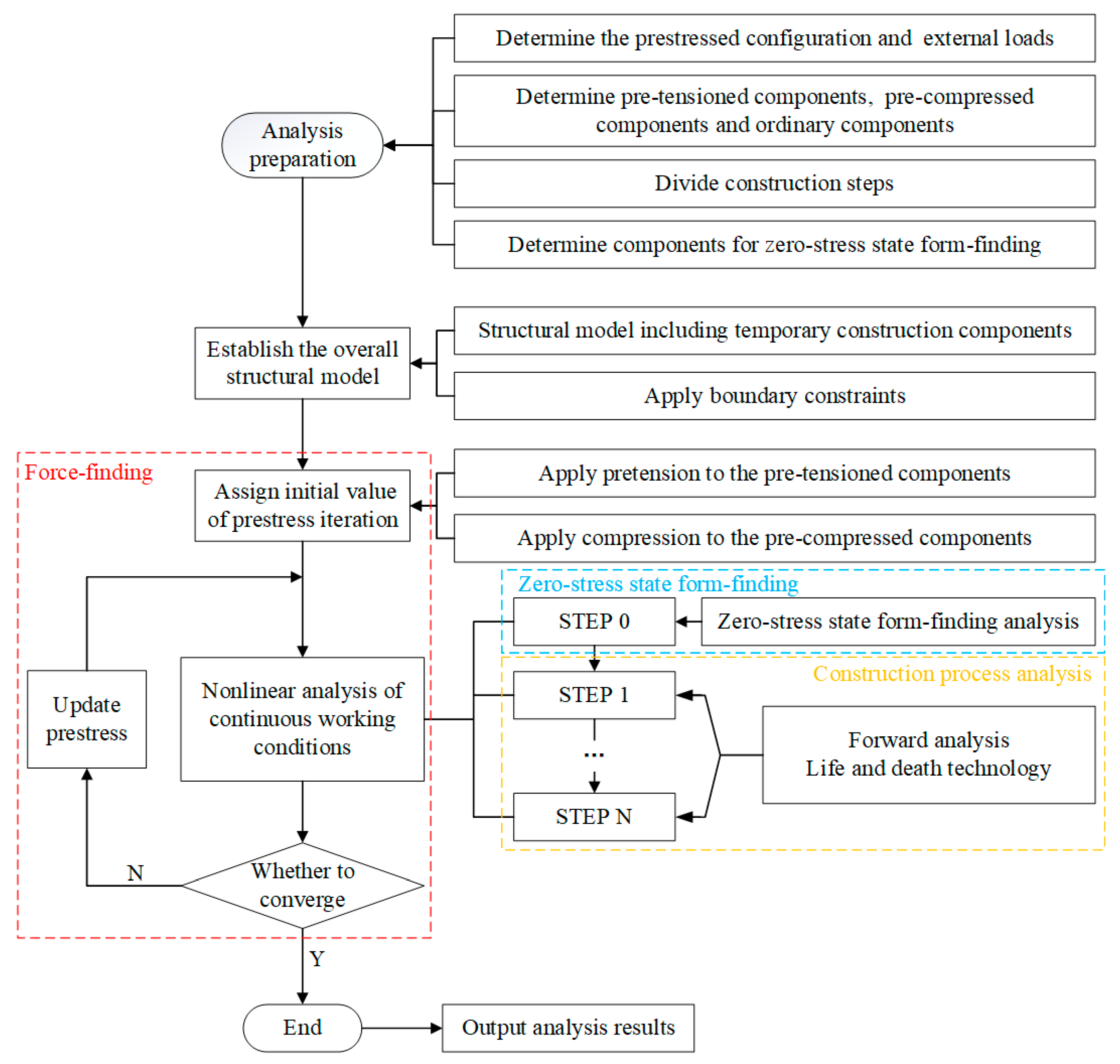
3. Prestress Self-Equilibrium Force-Finding Method (PSEFF) Considering Zero-Stress State Form-Finding and the Construction Process

Zero-stress state form-finding, construction process analysis, and prestressed state force-finding form a continuous and complete process, which accord to the actual forming process and are involved in the implementation of the PSEFF method proposed in this paper.

3.1. Preparatory Work

There are two main preparations before the computational analysis:
  • Classifying structural components into three categories: pretensioned, precompressed, and ordinary components. Prestress components are not restricted to cables. Considering the prestress self-balance, the pretensioned and precompressed components determined should form a prestress flow closed loop, establishing a self-balancing system. The prestress is not released due to structural deformation, thus providing effective stiffness for the structure. There is no prestress applied in ordinary components.
  • Determining the structural components participating in the zero-stress state form-finding. In general, structural components are not all assembled at one time. They are assembled step by step according to the construction scheme. Some components are installed before tensioning and others after tensioning. The structure is in the zero-stress state before tensioning; hence, those components assembled before tensioning are involved in the zero-stress state form-finding. The zero-stress state structure should be statically determined or as close to it as possible.

3.2. Application of Prestress

It is assumed that the components are invariably linearly elastic during the analysis. Force in the prestressed component k is given by:
P k = σ k P A k
where P k is the force applied in the component k during the iteration process; A k is the cross-sectional area of the component k; and σ k P is the axial stress caused by P k . Further, the axial stress σ k P can be expressed as:
σ k P = ε k P E k
where E k denotes the elastic modulus of the component k; and ε k P is the elastic strain of the component k caused by P k . The strain gives rise to a change in the component length, so ε k P can expressed as:
ε k P = Δ L k P L k 0 = L k P L k 0 L k 0
where L k 0 is the unstressed length of the component k; and L k P is the elongated length under P k .
In addition to the force that can elongate the component, the temperature can likewise change the component length due to thermal expansion and contraction. The strain is given in another way:
ε k T = Δ L k T L k 0 = Δ T k α k
where ε k T is the elastic strain of the component k caused by temperature difference Δ T k ; Δ L k T is the increment in component k length; and α k denotes the linear expansion coefficient of the component k.
Accordingly, the equivalent temperature difference is used to assign prestress in the components, and the relationship between them can be deduced as:
ε k T = ε k P
Δ T k = P k A k E k α k
The structural analysis model is established on the basis of the design configuration, including temporary support components. Tension is applied to pretensioned components, and pressure is applied to precompressed components.

3.3. Nonlinear Analysis

Zero-stress state form-finding and the subsequent construction process are continuously analyzed, which is a nonlinear process. Element birth and death technology is applied to simulate the process.
  • Zero-stress state form-finding: Activate the components participating in zero-stress state form-finding and kill other components. In the zero-stress state, the structural stress should be released fully, and the stress level is low. The zero-stress state is regarded as the initial state for subsequent construction analysis.
  • Construction process analysis: Adapt direct analysis. According to the construction steps divided in advance, gradually activate the assembled new components in each step until the structure achieves the design configuration. Ordinary components can be activated directly. The prestress in pretensioned and precompressed components is closely related to the unstressed length of the components. To obtain accurate results, it is necessary to ensure that the unstressed lengths of prestress components will not change during calculation. Therefore, the nodal co-ordinates of prestress components should be constrainedly moved to the design position before being activated.
The nonlinear equations can be written as [56]:
[ K ] { u } = { P }
where [K] is the stiffness matrix; {u} is the displacement vector; and {P} is total load vector. The Newton–Raphson method is employed to solve geometrically nonlinear problems. Assuming that { P } ( i 1 ) is the equilibrium load at the end of (i−1)-th iteration, the unbalanced load in the i-th iteration { Δ P } ( i ) is given by:
{ Δ P } ( i ) = { P } { P } ( i 1 )
The incremental displacement {Δu}(i)in the i-th iteration can be calculated by:
[ K ] ( i ) { Δ u } ( i ) = { Δ P } ( i )
where [ K ] ( i ) is the stiffness matrix in the i-th iteration.
The total displacement at the end of i-th iteration { u } ( i ) can be expressed as:
{ u } ( i ) = { u } ( i 1 ) + { Δ u } ( i )
The nodal coordinates of equilibrium state in i-th iteration {U} can be deduced as [3]:
{ U } = { U } ( i ) + { u } ( i )
where { U } ( i ) is the nodal co-ordinates of the zero-stress state in the i-th iteration.
The strain–displacement relationship under the equilibrium load {P}(i−1) can be expressed as:
{ ε } ( i 1 ) = [ B ] { u } ( i 1 )
where [ B ] is the strain matrix and contains two parts:
[ B ] = [ B 0 ] + [ B L ]
where [ B 0 ] is the strain matrix giving the linear strains and [ B L ] is the strain matrix giving nonlinear strains [57,58].
The incremental equilibrium equation can be written as:
{ ε } ( i 1 ) { σ } ( i 1 ) d V { u } ( i 1 ) T { P } ( i 1 ) = 0
The stress–strain relationship can be expressed as:
{ σ } ( i 1 ) = [ D ] { ε } ( i 1 )
where [D] denotes the stress–strain relationship matrix.
Substituting Equations (12) and (15) into Equation (14) yields
{ P } ( i 1 ) = [ B ] T [ D ] { ε } ( i 1 ) d V

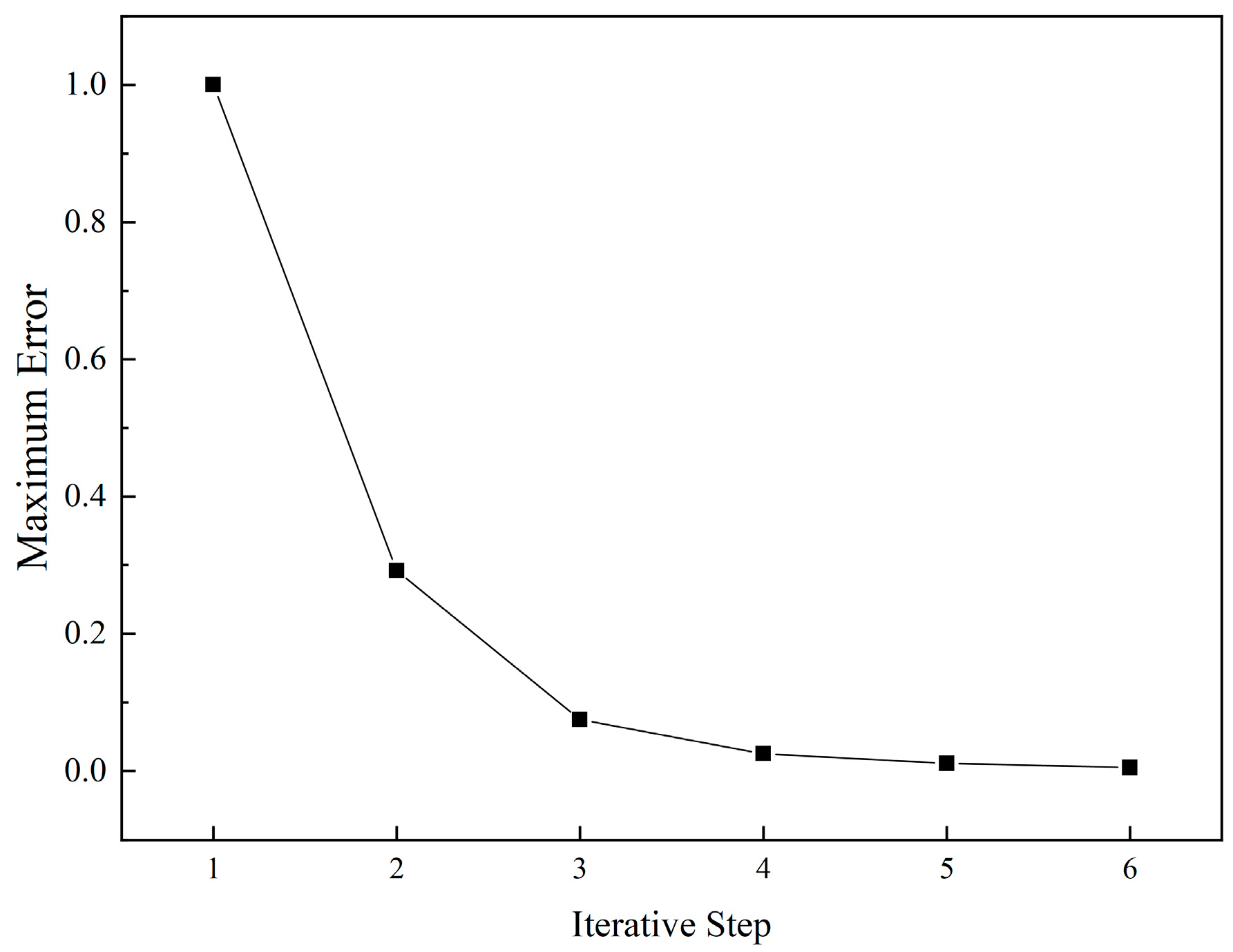
3.4. Convergence Criterion

The convergence criterion for the analysis process is given by:
Δ σ k ( i ) σ k ( i ) N = σ k ( i ) N σ k ( i 1 ) P σ k ( i ) N < δ
where σ k ( i ) N is the stress of the component k after i-th iteration; σ k ( i 1 ) P is the prestress iteration initial value for i-th iteration; and δ denotes the tolerance to judge the force-finding results (δ = 0.005 in this study)
σ k ( i ) P = σ k ( i ) N
where σ k ( i ) P is the prestress iteration initial value for (i+1)-th iteration. The nonlinear analysis process is repeated until it converges.
The flow of the PSEFF method is summarized in Figure 3. It should be noted that zero-stress state form-finding, construction analysis, and force-finding are included in one cycle rather than three independent steps. Additionally, the method dispenses with updating the model configuration during calculation. Zero-stress state configuration, structural states during construction, and prestress distribution can be obtained simultaneously.

4. Practical Application

4.1. FEM Model

4.1.1. Element Type

The structural model is built in general finite element software ANSYS (version 2019 R1), taking Shanghai Pudong Football Stadium as the analysis object. The PSEFF method described explicitly in Section 3 is written by the ANSYS parametric design language (APDL). Activating or killing the components simulates the construction process. On account of the high prestress level in cables, the self-weight of cables can be negligible. Hence, the LINK180 element is a two-node straight rod element with no bending moment at the end, which is adopted to simulate the cables. In addition, it is also used for steel tie rods, buckling–restrained braces (BRB), and columns. The BEAM188 element, a 3D beam element based on the Timoshenko beam theory, is used for radial girders, beam rings, compression rings, and V columns. Each node of the BEAM188 element has six or seven degrees of freedom, including translational and rotational degrees of freedom in the x, y, and z directions and an optional warping degree of freedom. The COMBIN14 element with a damping spring is set at the bottom of the column to consider the stiffness of the lower concrete stand. The MASS21 and SURFL54 elements are adopted to simulate cable clamp and roof membrane, respectively.

4.1.2. Material Properties

The tensile grade of steel components is Q390C. Radial and hoop cables are full locked coil ropes with a tensile strength of 1670 MPa. The material properties of steel components and cables are listed in Table 2.

4.1.3. Connection Joint

The top and bottom ends of the columns are hinge joints, and vertical spring supports are set at the bottom ends of the columns. The connections between the internal compression ring, ring beams, and radial girders are rigid joints. Additionally, apart from the rest of the components, such as cables, V columns, BRBs, and steel tie rods, both ends are hinged joints.

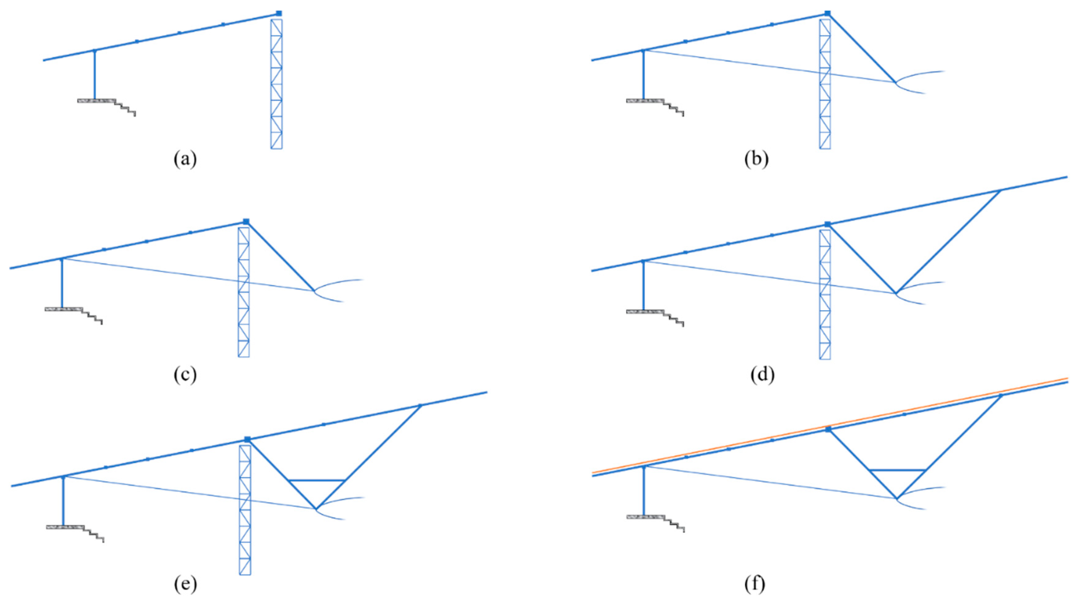
4.2. Construction Steps and Components Division

The construction process can be regarded as the cumulative installation process of different types of components, and the reasonable division of construction steps affects the forming accuracy of the structure. In the actual construction, jig frames are set to install the internal compression ring. Jig frames can be compressed or tensioned, which invariably limits the elevation of the internal compression ring to the design position to control the structural configuration during the construction process. There are eight closure segments in the upper rigid grid, as shown in Figure 4, to ensure that the pressure in the radial girders can be effectively transmitted to the internal compression ring, and to avoid the whole rigid grid from being under pressure. The internal compression ring divides the upper radial grid into inner and outer parts. The pivotal construction steps are divided as follows and shown in Figure 5.
Step 1: Install jig frames, columns, internal compression ring, outer radial girders, and outer ring beams (excluding eight closure segments);
Step 2: Assemble V columns’ outer branches, hoop cables, cable clamps, and radial cables; tension the radial cables to apply prestress to the structure;
Step 3: Install BRB, ring beams of closure segments, and outer roof bracing;
Step 4: Install V columns’ inner branches and inner radial girders;
Step 5: Install inner ring beams and inner roof bracing;
Step 6: Install membrane roof and catwalk, and dismantle jig frames.
Zero-stress state form-finding components: columns, ring transfer beam, internal compression ring, and outer radial girders.
Force-finding components: radial cables, radial girders, internal compression ring, hoop cables, and V columns’ outer and inner branches.

4.3. Zero-Stress State Form-Finding Results

The most important characteristic of the structure in the zero-stress state is that the structural stress is zero or close to zero. Figure 6 shows that in the zero-stress state obtained by the PSEFF method, the maximum stress of the form-finding structure is 6.1 MPa, and that of the internal compression ring is 1.0 MPa. The stress level of the structure is extremely low, indicating that the prestress in zero-stress state form-finding components has been fully released. The release of the prestress is accompanied by the outward expansion of the structure.
Table 3 lists the structural displacements in the zero-stress state, which is relative to the design configuration. After form-finding analysis, the structure expands outward in both the long and short axis directions, and the displacement in the long axis is larger than that in the short axis direction. Due to the restriction of the jig frames, the horizontal displacements of the internal compression ring in the x and y directions are smaller than that of the ring transfer beam. The extremely low stress level and horizontal extension of the structure prove that the correct zero-stress state configuration can be obtained by the PSEFF method. The components should be assembled in the zero-stress state configuration as the starting point of the construction process.

4.4. Force-Finding Results

In this study, the convergence criterion is δ = 0.005. The PSEFF method has fast convergence speed. As shown in Figure 7, the maximum error of force-finding declines rapidly. After six iterations, the maximum error is 0.0049, which meets the convergence criterion.
Considering the symmetry of the structure, a quarter of the structure is selected to illustrate the analysis results, and axis numbers are shown in Figure 2d. The radial cable force distribution after the structure is completed is shown in Figure 8. All the radial cables are in tension without slack. Due to the curvature variation of the internal compression ring, the radial cable force is divided into three levels according to their position: corner > short side > long side. The radial cable, with the maximum force value of 5058.5 kN, is located at axis six of the corner. The prestress distribution is consistent with the design state, and the maximum cable force deviation is 8%, which shows the effectiveness of the PSEFF method.
As can be observed from Figure 9, the V column outer branches at the corner are in tension, while the others are in compression. Since the radial cable force at the corner is relatively large, the elevation of the hoop cables at the corner is raised to reduce the tension in the radial cables, which conduces to the V column outer branches being tensioned.
The forces of hoop cables are listed in Table 4.
Figure 10 shows the stress of the upper rigid grid after the structure is completed. It can be seen that the stress in the radial girders and internal compression ring has a higher level but is lower elsewhere. This indicates that the prestress is effectively transmitted to the internal compression ring through the radial girders rather than the entire upper rigid grid to balance the prestress, which meets the design requirements.

4.5. Construction Process Analysis

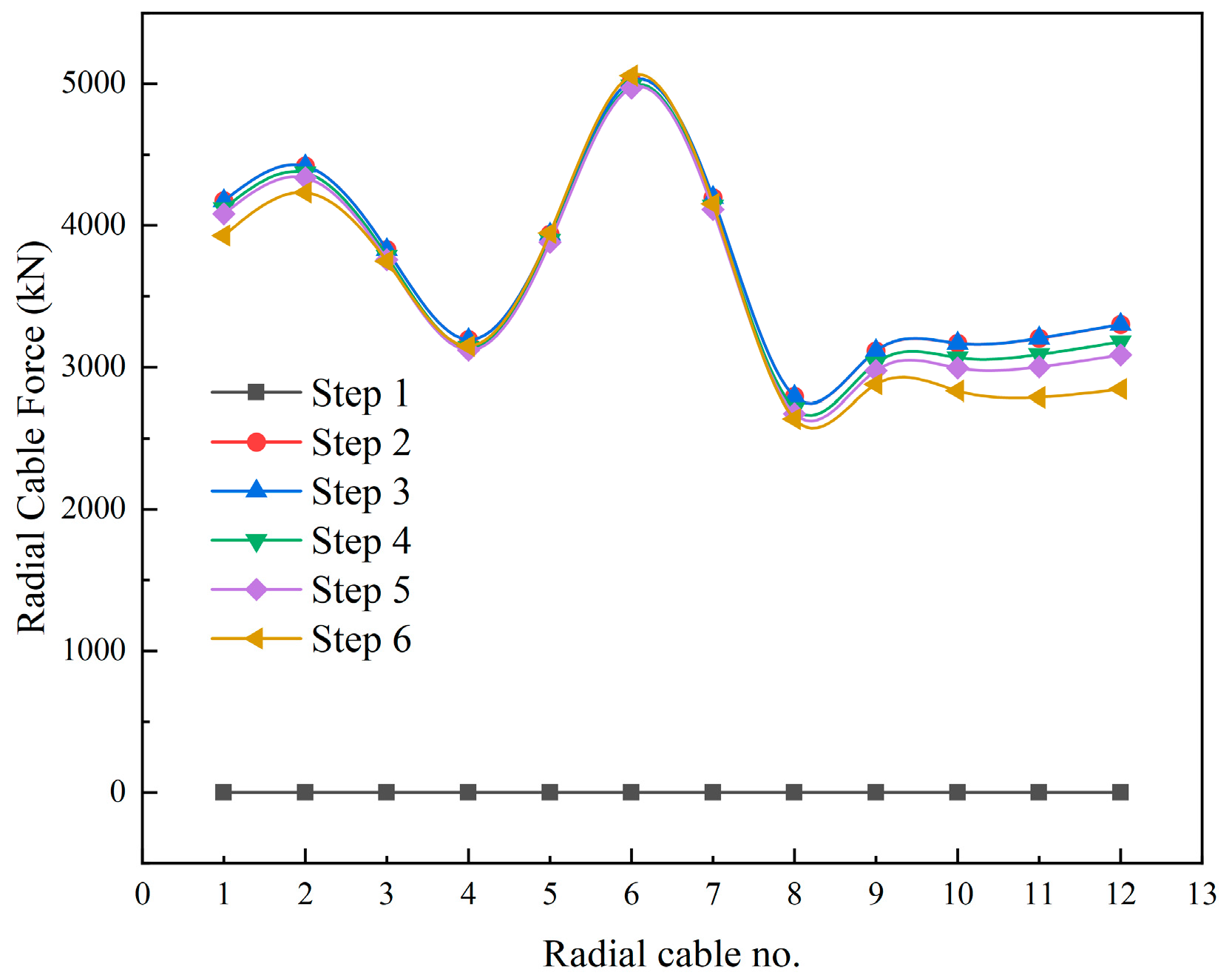
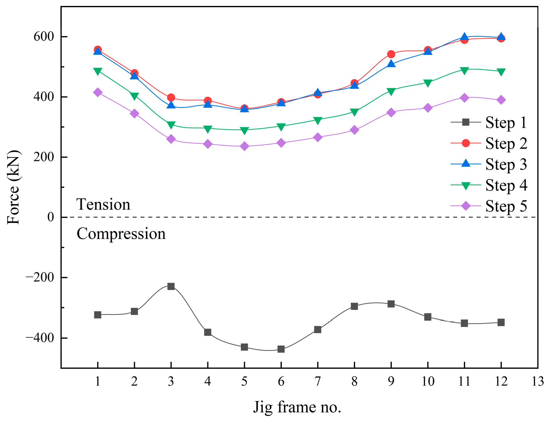
4.5.1. Internal Force
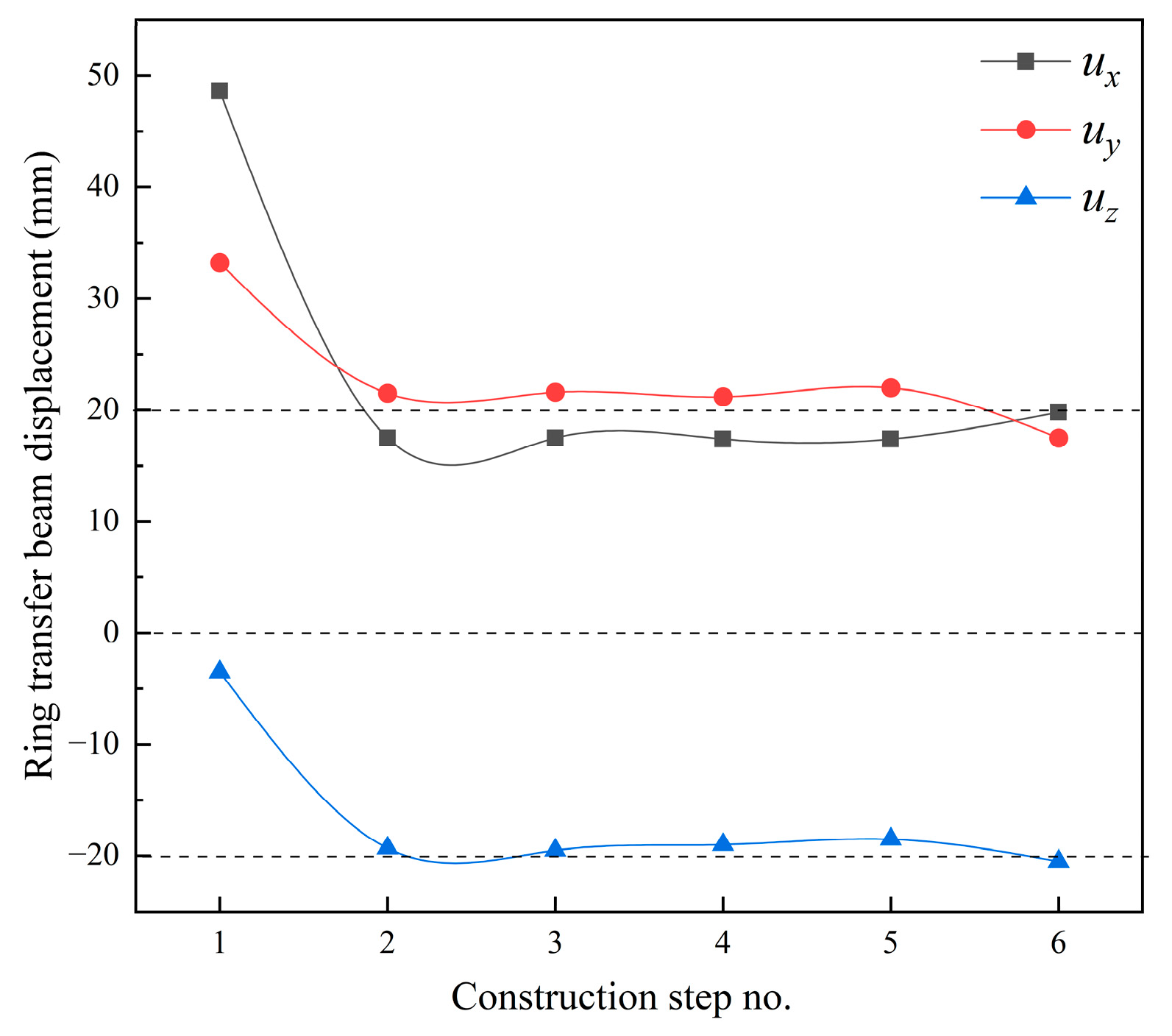
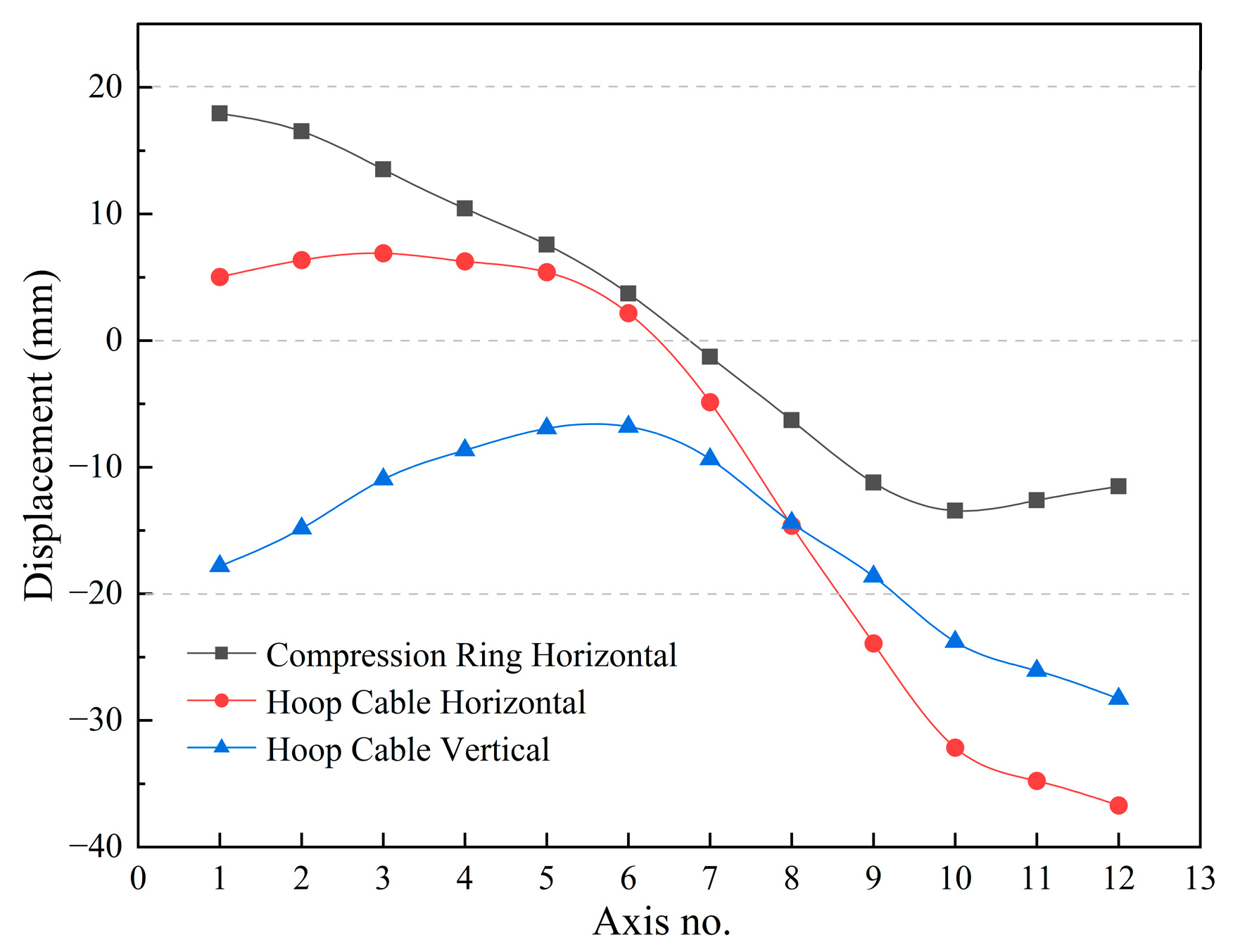
After the radial cable tensioning is completed until the structure is fully formed, the radial cable force does not change much, and the radial cable force at the long and short sides decreases slightly, as shown in Figure 11. Table 5 lists the internal force of the hoop cables, internal compression ring, and upper rigid grid during the construction process. The initial axial force of the internal compression ring is merely 9.51 kN, which is close to 0; after the radial cable is tensioned, the internal compression ring is transformed into a compressed state. Neither the cable force nor the axial force of the internal compression ring has changed dramatically because of the restriction of the jig frames to the internal compression ring configuration. The maximum equivalent stress of the upper rigid grid also increases significantly in Step 2. After the jig frames are dismantled, it increases to 130.5 MPa. The structure is in an elastic state throughout the construction process.
The jig frames are arranged under the internal compression ring. The force variation in jig frames is shown in Figure 12. Structural stiffness has not yet been generated until the prestress is applied. Part of the structural self-weight is borne by the jig frames, which are in compression. With tensioning of the radial cables completed, jig frames become in tension, and the tension of the corner jig frames is the smallest among all jig frames. The installation of the following components reduces the tension, but jig frames will remain in tension until they are dismantled. Therefore, the vertical cables are set in the jig frames to prevent the internal compression ring from leaving the jig frames in the actual construction. This measure can effectively control the structural configuration during the construction process.

4.5.2. Displacement

In step 1, the structure is in the zero-stress state, with horizontal outward expansion relative to the design configuration. After the prestress is applied, the structure gradually shrinks inward, approaching the design configuration. The variation trend of the ring transfer beam displacement is shown in Figure 13. After the structure develops its own stiffness, the structural self-weight is borne entirely by the columns, and the vertical displacement of the column top increases. With the installation of subsequent components, the vertical displacement further increases to −20.5 mm. The displacements of the internal compression ring and hoop cables are shown in Figure 14. Given the actual size of the structure, the vertical and horizontal displacement deviations are within an acceptable limit, i.e., 1/1000 of the structural span or plane size.
The above analysis results provided essential guidance for the project’s actual construction, and the structure successfully achieved the expected configuration.

5. Discussion

The previous studies carried out zero-stress state form-finding, construction process analysis, and force-finding independently. In fact, the three are a continuous process. The prestress self-equilibrium force-finding (PSEFF) method proposed in this paper takes into account the zero-stress state form-finding and construction process. Through one analysis, the zero-stress state configuration, the structural response during the construction process, and the prestress distribution can be gained simultaneously, which improves the analysis efficiency. The critical technical measures of this method include the classification of prestressed components and ordinary components, nonlinear analysis, and the activation principle of prestressed components. The method has been successfully applied to the CSGS with an internal compression ring with precise results obtained. In the zero-stress state configuration obtained by this method, the structural stress is fully released. The division of construction steps is consistent with the existing scheme, so the structural response during the construction process in the analysis results becomes a significant basis for the actual construction. The prestress distribution and displacements of the formed structure are in accordance with the designer’s expectations.
It is necessary to note some issues in the application of the method. There are specific preparations before the analysis. The most crucial thing is to establish a prestress self-equilibrium system by reasonably dividing pretensioned and precompressed components. It should be ensured that the unstressed lengths of the prestress components remain unchanged in the calculation. A rational construction scheme is also a crucial factor affecting the precision of the analysis.
Furthermore, this method is only validated in the CSGS with an internal compression ring. Its practicability for other prestress structures such as cable-net structures, cable domes, etc., remains to be studied.

6. Conclusions

In this study, we developed a prestress self-equilibrium force-finding (PSEFF) method for CSGS with an internal compression ring considering zero-stress state form-finding and the construction process, and its validity and accuracy have been verified through an actual project. Based on the work of the paper, the conclusions are summarized as follows:
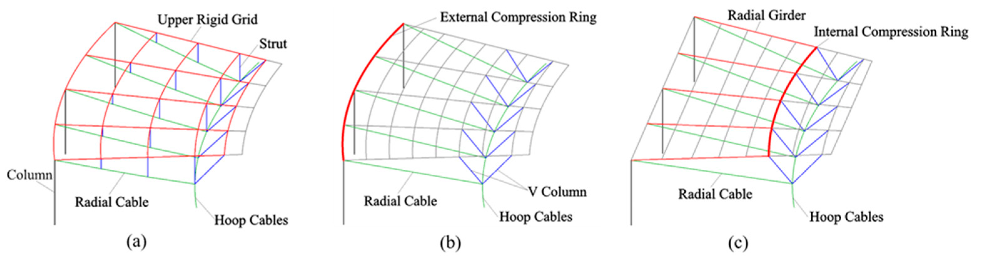
  • CSGS with an internal compression ring is a new structure combining rigidity and flexibility. The compression ring is located inside the structure and not restricted by the plane shape, which ensures that the internal forces of the compression ring are mainly axial force and which reduces the bending stress.
  • The equivalent temperature difference is applied to the components as prestress. The Newton–Raphson method is employed to solve nonlinear problems. The structural finite element model is built to implement the analysis. To acquire the accurate structural configuration and prestress distribution, the prestressed components should form a self-balancing system, and their unstressed length ought to be constant during the calculation.
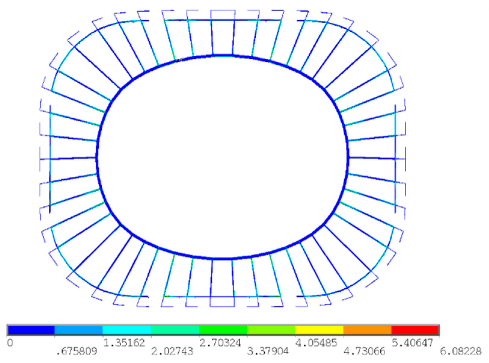
  • Compared with the design configuration, the zero-stress state configuration expands horizontally, and the internal forces are completely released. The internal forces and displacements are relatively stable in the construction steps after prestressing. The prestress distribution and displacements of the formed structure are in accordance with the designer’s expectations. The maximum deviation of radial cable force is 8%, and the displacement deviations are within 1/1000. The analysis results demonstrate the effectiveness of the PSEFF method.
  • The PSEFF method proposed in this paper has been successfully applied to the forming analysis of CSGS with an internal compression ring. Accurate zero-stress state configuration and feasible prestress actual response during the construction process can be obtained at one time. The versatility of the method for other cable-strut structures and the efficiency improvement compared with other methods should be studied further.

Author Contributions

Conceptualization, N.Z.; methodology, B.L.; software, B.L; validation, N.Z., B.L. and H.L.; formal analysis, H.L; investigation, N.Z.; resources, B.L.; data curation, B.L.; writing—original draft preparation, N.Z.; writing—review and editing, H.L. and M.Z.; visualization, N.Z. and M.Z.; supervision, B.L.; project administration, B.L.; funding acquisition, B.L. All authors have read and agreed to the published version of the manuscript.

Funding

The research was funded by the National Natural Science Foundation of China (grant number 11673039).

Institutional Review Board Statement

Not applicable.

Informed Consent Statement

Not applicable.

Data Availability Statement

All data that support the findings of this study are available from the corresponding author upon reasonable request.

Conflicts of Interest

The authors declare no conflict of interest.

References

  1. Kawaguchi, M.; Abe, M.; Tagemichi, I. Design, tests and realization of “suspen-dome” system. J. Int. Assoc. Shell Spat. Struct. 1999, 40, 179–192. [Google Scholar]
  2. Kang, W.; Chen, Z.; Lam, H.F.; Zuo, C. Analysis and design of the general and outmost-ring stiffened suspendome structures. Eng. Struct. 2003, 25, 1685–1695. [Google Scholar] [CrossRef]
  3. Liu, H.; Zhang, W.; Yuan, H.; Zhu, J.; Zheng, J. Modified double-control form-finding analysis for suspendomes considering the construction process and the friction of cable–strut joints. Eng. Struct. 2016, 120, 75–81. [Google Scholar] [CrossRef]
  4. Krishnan, S. Cable-stayed columns and their applications in building structures. J. Build. Eng. 2020, 27, 100984. [Google Scholar] [CrossRef]
  5. Feng, Y.; Xiang, X.; Wang, H.; Chen, W. Mechanical behavior and form-finding research on large opening spoke-wheel-type cable supported grid structure. J. Build. Struct. 2019, 40, 69–80. [Google Scholar] [CrossRef]
  6. Feng, Y.; Xiang, X.; Wang, H. Static performance parameter analysis of large opening spoke-wheel-type cable supported grid structure. J. Build. Struct. 2019, 40, 81–91. [Google Scholar] [CrossRef]
  7. Zhang, Z.; Cao, Q.; Dong, S.; Fu, X. Structural design of a practical suspendome. Adv. Steel Constr. 2008, 4, 323–340. [Google Scholar]
  8. Wang, Y.; Xu, X.; Luo, Y. A unifying framework for form-finding and topology-finding of tensegrity structures. Comput. Struct. 2021, 247, 106486. [Google Scholar] [CrossRef]
  9. Chen, L.; Dong, S. Optimal Prestress Design and Construction Technique of Cable-Strut Tension Structures with Multi-Overall Selfstress Modes. Adv. Struct. Eng. 2013, 16, 1633–1644. [Google Scholar] [CrossRef]
  10. Li, X.; Xue, S.; Liu, Y. A novel form finding method for minimum surface of cable net. J. Build. Eng. 2022, 48, 103939. [Google Scholar] [CrossRef]
  11. Nie, R.; He, B.; Hodges, D.H.; Ma, X. Form finding and design optimization of cable network structures with flexible frames. Comput. Struct. 2019, 220, 81–91. [Google Scholar] [CrossRef]
  12. Deng, H.; Jiang, Q.; Kwan, A.S.K. Shape finding of incomplete cable-strut assemblies containing slack and prestressed elements. Comput. Struct. 2005, 83, 1767–1779. [Google Scholar] [CrossRef]
  13. Zhao, J.; Chen, W.; Fu, G.; Li, R. Computation method of zero-stress state of pneumatic stressed membrane structure. Sci. China Technol. Sci. 2012, 55, 717–724. [Google Scholar] [CrossRef]
  14. Tang, Y.; Li, T.; Ma, X.; Hao, L. Extended Nonlinear Force Density Method for Form-Finding of Cable-Membrane Structures. J. Aerosp. Eng. 2017, 30, 4016101. [Google Scholar] [CrossRef]
  15. Tang, Y.; Li, T. Equivalent-force density method as a shape-finding tool for cable-membrane structures. Eng. Struct. 2017, 151, 11–19. [Google Scholar] [CrossRef]
  16. Shi, J.; Zhao, J.; Tsukimoto, S.; Shimoda, M. Design optimization of cable–membrane structures for form-finding and stiffness maximization. Compos. Struct. 2020, 206, 9–22. [Google Scholar] [CrossRef]
  17. Su, Y.; Zhang, J.; Ohsaki, M.; Wu, Y. Topology optimization and shape design method for large-span tensegrity structures with reciprocal struts. Int. J. Solids Struct. 2018, 192, 528–536. [Google Scholar] [CrossRef]
  18. Zhang, L.; Zhu, S.; Li, S.; Xu, G. Analytical form-finding of tensegrities using determinant of force-density matrix. Compos. Struct. 2018, 189, 87–98. [Google Scholar] [CrossRef]
  19. Pagitz, M.; Mirats Tur, J.M. Finite element based form-finding algorithm for tensegrity structures. Int. J. Solids Struct. 2009, 46, 3235–3240. [Google Scholar] [CrossRef]
  20. Yuan, S.; Zhu, W. Optimal self-stress determination of tensegrity structures. Eng. Struct. 2021, 238, 112003. [Google Scholar] [CrossRef]
  21. Dong, W.; Stafford, P.J.; Ruiz-Teran, A.M. Inverse form-finding for tensegrity structures. Comput. Struct. 2019, 215, 27–42. [Google Scholar] [CrossRef] [Green Version]
  22. Bagrianski, S.; Halpern, A.B. Form-finding of compressive structures using Prescriptive Dynamic Relaxation. Comput. Struct. 2014, 132, 65–74. [Google Scholar] [CrossRef]
  23. Domaneschi, M.; Limongelli, M.G.; Martinelli, L. Multi-site damage localization in a suspension bridge via aftershock monitoring. Ing. Sismica 2013, 30, 56–72. [Google Scholar]
  24. Wang, X.; Wang, H.; Zhang, J.; Sun, Y.; Bai, Y.; Zhang, Y.; Wang, H. Form-finding method for the target configuration under dead load of a new type of spatial self-anchored hybrid cable-stayed suspension bridges. Eng. Struct. 2021, 227, 11407. [Google Scholar] [CrossRef]
  25. Martinelli, L.; Domaneschi, M.; Shi, C. Submerged Floating Tunnels under Seismic Motion: Vibration Mitigation and Seaquake effects. Procedia Eng. 2016, 166, 229–246. [Google Scholar] [CrossRef]
  26. Zhang, P.; Zhou, J.; Chen, J. Form-finding of complex tensegrity structures using constrained optimization method. Compos. Struct. 2021, 268, 113971. [Google Scholar] [CrossRef]
  27. Schek, H.J. The force density method for form finding and computation of general networks. Comput. Methods Appl. Mech. Eng. 1974, 3, 115–134. [Google Scholar] [CrossRef]
  28. Linkwitz, K.; Schek, H.J. Einige Bemerkungen zur Berechnung von vorgespannten Seilnetzkonstruktionen. Ing. Arch. 1971, 40, 145–158. [Google Scholar] [CrossRef]
  29. Cai, J.; Wang, X.; Deng, X.; Feng, J. Form-finding method for multi-mode tensegrity structures using extended force density method by grouping elements. Compos. Struct. 2018, 187, 1–9. [Google Scholar] [CrossRef]
  30. Koohestani, K. Innovative numerical form-finding of tensegrity structures. Int. J. Solids Struct. 2020, 206, 304–313. [Google Scholar] [CrossRef]
  31. Otter, J.R.H.; Cassell, A.C.; Hobbs, R.E. Poisson, Dynamic relaxation. Proc. Inst. Civ. Eng. 1966, 35, 633–656. [Google Scholar] [CrossRef]
  32. Day, A.S.; Bunce, J.H. Analysis of cable networks by dynamic relaxation. Civ. Eng. Public Work. Rev. 1970, 4, 383–386. [Google Scholar]
  33. Barnes, M.R. Form Finding and Analysis of Tension Structures by Dynamic Relaxation. Int. J. Space Struct. 1999, 14, 89–104. [Google Scholar] [CrossRef]
  34. Argyris, J.H.; Angelopoulos, T.; Bichat, B. A general method for the shape finding of lightweight tension structures. Comput. Methods Appl. Mech. Eng. 1974, 3, 135–149. [Google Scholar] [CrossRef]
  35. Domaneschi, M. Experimental and numerical study of standard impact tests on polypropylene pipes with brittle behavior. Proc. Inst. Mech. Eng. Part B 2012, 226, 2035–2046. [Google Scholar] [CrossRef]
  36. Domaneschi, M.; Perego, U.; Borgqvist, E.; Borsari, R. An industry-oriented strategy for the finite element simulation of paperboard creasing and folding. Packag. Technol. Sci. 2017, 30, 269–294. [Google Scholar] [CrossRef]
  37. Tanarrok, B.; Qin, Z. Nonlinear analysis of tension structures. Comput. Struct. 1992, 45, 973–984. [Google Scholar] [CrossRef]
  38. Lee, S.; Lee, J. Form-finding of tensegrity structures with arbitrary strut and cable members. Int. J. Mech. Sci. 2014, 85, 55–62. [Google Scholar] [CrossRef]
  39. Quagliaroli, M.; Albertin, A.; Pollini, N. The role of prestress and its optimization in cable domes design. Comput. Struct. 2015, 161, 17–30. [Google Scholar] [CrossRef]
  40. Zhang, Q.; Wang, X.; Cai, J.; Yang, R.; Feng, J. Prestress design for cable-strut structures by grouping elements. Eng. Struct. 2021, 244, 112010. [Google Scholar] [CrossRef]
  41. Sun, F.; Zhu, D.; Liang, M.; Zhang, D. Study on Form-Finding of Cable-Membrane Structures Based on Particle Swarm Optimization Algorithm. Math. Probl. Eng. 2020, 2020, 1281982. [Google Scholar] [CrossRef]
  42. Chen, Y.; Yan, J.; Feng, J.; Sareh, P. A hybrid symmetry–PSO approach to finding the self-equilibrium configurations of prestressable pin-jointed assemblies. Acta Mech. 2020, 231, 1485–1501. [Google Scholar] [CrossRef]
  43. Li, Y.; Feng, X.; Cao, Y.; Gao, H. A Monte Carlo form-finding method for large scale regular and irregular tensegrity structures. Int. J. Solids Struct. 2010, 47, 1888–1898. [Google Scholar] [CrossRef] [Green Version]
  44. Ye, J.; Feng, R.; Zhao, X.; Liu, B. A form-finding method of beam string structures-Offload by steps method. Int. J. Steel Struct. 2012, 12, 267–283. [Google Scholar] [CrossRef]
  45. Fan, L.; Sun, Y.; Fan, W.; Chen, Y.; Feng, J. Determination of active members and zero-stress states for symmetric prestressed cable–strut structures. Acta Mech. 2020, 231, 3607–3620. [Google Scholar] [CrossRef]
  46. Pellegrino, S. Analysis of prestressed mechanisms. Int. J. Solids Struct. 1990, 26, 1329–2350. [Google Scholar] [CrossRef]
  47. Pellegrino, S. Structural computations with the singular value decomposition of the equilibrium matrix. Int. J. Solids Struct. 1993, 30, 3025–3035. [Google Scholar] [CrossRef]
  48. Pellegrino, S.; Calladine, C.R. Matrix analysis of statically and kinematically indeterminate frameworks. J. Solids Struct. 1986, 22, 409–428. [Google Scholar] [CrossRef]
  49. Yuan, X.; Dong, S. Integral feasible prestress of cable domes. Comput. Struct. 2003, 81, 2111–2119. [Google Scholar] [CrossRef]
  50. Yuan, X.; Chen, L.; Dong, S. Prestress design of cable domes with new forms. Int. J. Solids Struct. 2007, 44, 2773–2782. [Google Scholar] [CrossRef] [Green Version]
  51. Guo, J.; Jiang, J. An algorithm for calculating the feasible pre-stress of cable-struts structure. Eng. Struct. 2016, 118, 228–239. [Google Scholar] [CrossRef]
  52. Chen, L.; Hu, D.; Deng, H.; Cui, Y.; Zhou, Y. Optimization of the construction scheme of the cable-strut tensile structure based on error sensitivity analysis. Steel Compos. Struct. 2016, 21, 1031–1043. [Google Scholar] [CrossRef]
  53. Li, Y.; Zhang, G.; Yang, Q. Determination of cable forces during construction for cable-supported lattice shells. J. Build. Struct. 2004, 24, 76–81. [Google Scholar] [CrossRef]
  54. Yuan, X.; Dong, S. Inverse Analysis of Construction Process of Cable Dome. J. Build. Struct. 2001, 22, 75–80. [Google Scholar] [CrossRef]
  55. Luo, B.; Guo, Z.; Chen, X.; Gao, F.; Wang, K. Static equilibrium form-finding analysis of cable-strut system based on nonlinear dynamic finite element method. Adv. Steel Constr. 2005, 11, 452–468. [Google Scholar]
  56. Zienkiewicz, O.C.; Taylor, R.L. The Finite Element Method for Solid and Structural Mechanics, 6th ed.; Elsevier: Oxford, UK, 2005. [Google Scholar]
  57. Pica, A.; Wood, R.D.; Hinton, E. Finite element analysis of geometrically nonlinear plate behaviour using a mindlin formulation. Comput. Struct. 1980, 11, 203–215. [Google Scholar] [CrossRef]
  58. Surana, K.S. Geometrically non-linear formulation for two dimensional curved beam elements. Comput. Struct. 1983, 17, 105–114. [Google Scholar] [CrossRef]
Figure 1. Three categories of CSGS: (a) upper grid as a whole compression ring; (b) external compression ring; (c) internal compression ring.
Buildings 12 00749 g001
Figure 2. Schematic of Pudong Football Stadium: (a) effect picture; (b) three-dimensional view; (c) plan view; (d) radial cable distribution; (e) node detail diagram.
Buildings 12 00749 g002
Figure 3. Flow chart of the PSEFF.
Buildings 12 00749 g003
Figure 4. Position of upper-grid closure segments.
Buildings 12 00749 g004
Figure 5. Construction process: (a) Step 1, (b) Step 2, (c) Step 3, (d) Step 4, (e) Step 5, (f) Step 6.
Buildings 12 00749 g005
Figure 6. Structural stress in zero-stress state.
Buildings 12 00749 g006
Figure 7. Iterative convergence of the PSEFF method.
Buildings 12 00749 g007
Figure 8. Radial cable force distribution after force-finding analysis.
Buildings 12 00749 g008
Figure 9. Axial force in V column outer branches after force-finding analysis.
Buildings 12 00749 g009
Figure 10. Stress in upper rigid grid after force-finding analysis.
Buildings 12 00749 g010
Figure 11. Radial cable force variation during the construction process.
Buildings 12 00749 g011
Figure 12. Force variation in the jig frames during the construction process.
Buildings 12 00749 g012
Figure 13. Ring transfer beam displacements variation during the construction process.
Buildings 12 00749 g013
Figure 14. Displacement variation of compression ring and hoop cable during the construction process.
Buildings 12 00749 g014
Table 1. Component specifications.
Section TypeComponentSectional Dimension (mm)
Rectangular tubeInternal compression ring1500 × 1500 × 50 × 50
Radial girder650 × 650 × 14 × 22
Ring beam1400 × 700 × 10 × 48
V column600 × 350 × 12 × 12
Circular tubeColumn400 × 10
Table 2. Component material properties.
Component TypeDensity (kg/m3)Young’s Elastic
Modulus (MPa)
Linear Expansion
Coefficient (1/°C)
Poisson’s Ratio
Radial & Hoop cables78501.60 × 1051.2 × 10−50.3
Steel Components8635 12.06 × 1051.2 × 10−50.3
1 The density of steel components takes into account the mass of the stiffeners and joints.
Table 3. The structural displacements in the zero-stress state.
ComponentDisplacement (mm)
In the Long Axis Direction uxIn the Short Axis Direction uyVertical Displacement uz
Internal compression ring34.623.93.2
Ring transfer beam46.532.7−0.1
Table 4. The force of hoop cables.
ComponentHoop Cable No.
12345678
Force (kN)3398.43165.73493.33282.73604.93403.73733.93527.6
Table 5. Internal forces during the construction process.
Internal ForcesConstruction Step No.
123456
Hoop cables average force (kN)03276.33276.43317.93341.53451.3
Compression ring axial force (kN)9.51−26,100−26,100−26,500−26,600−27,200
Upper rigid grid stress (MPa)42.5112.6115.1111.4110.9130.5
Publisher’s Note: MDPI stays neutral with regard to jurisdictional claims in published maps and institutional affiliations.

