
Earth to Earth: Patterns of Environmental Decay Affecting Modern Pisé Walls


Abstract
1. Introduction
2. Methodology
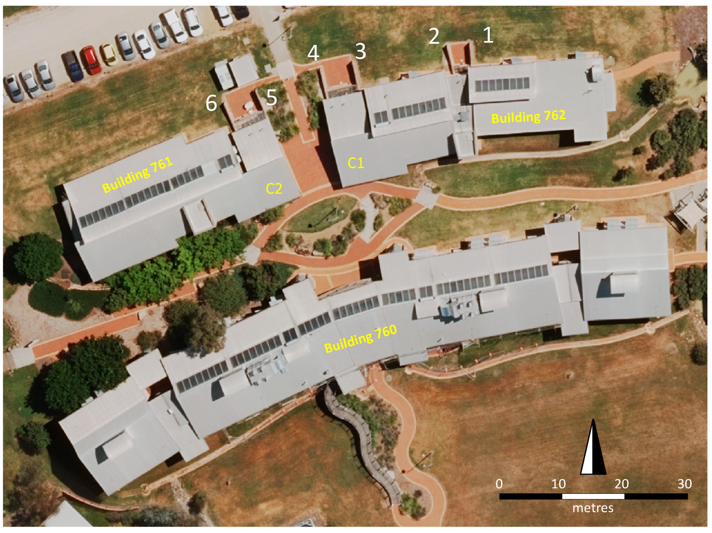
2.1. Study Site
2.2. Assessment and Documentation
2.3. Environmental Settings
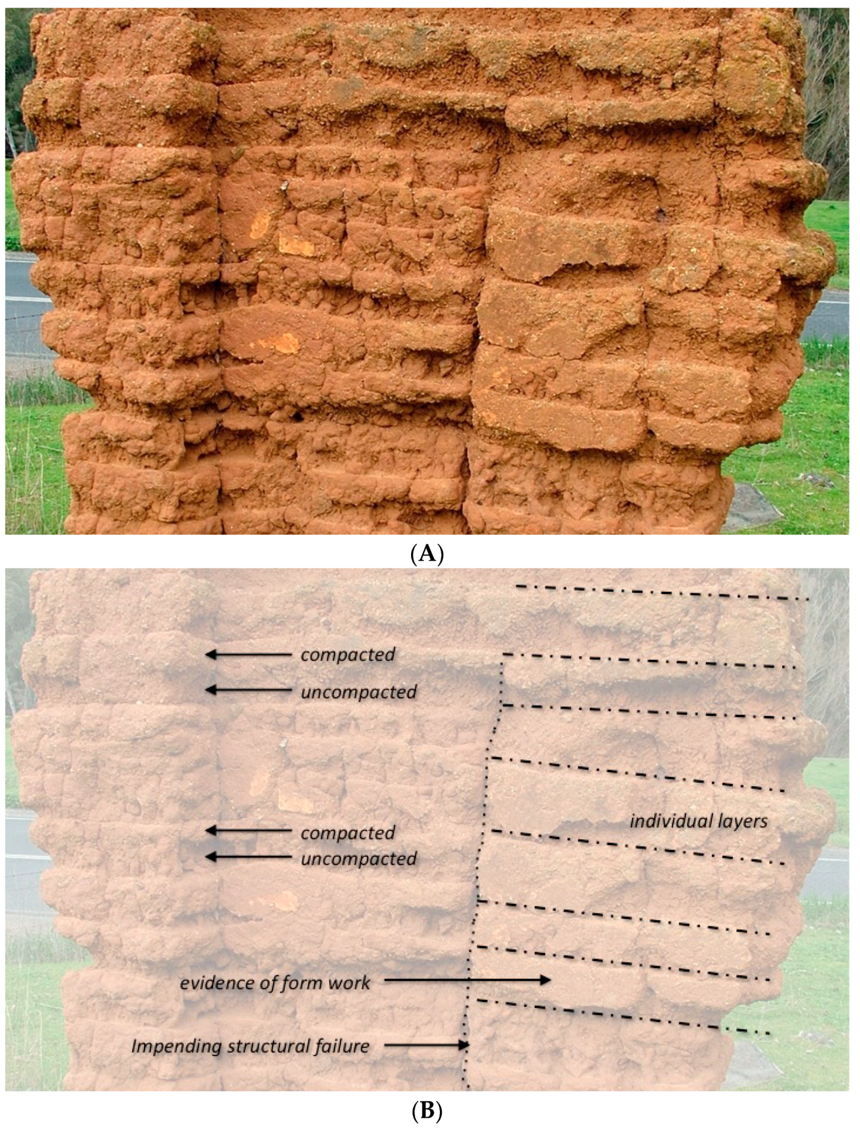
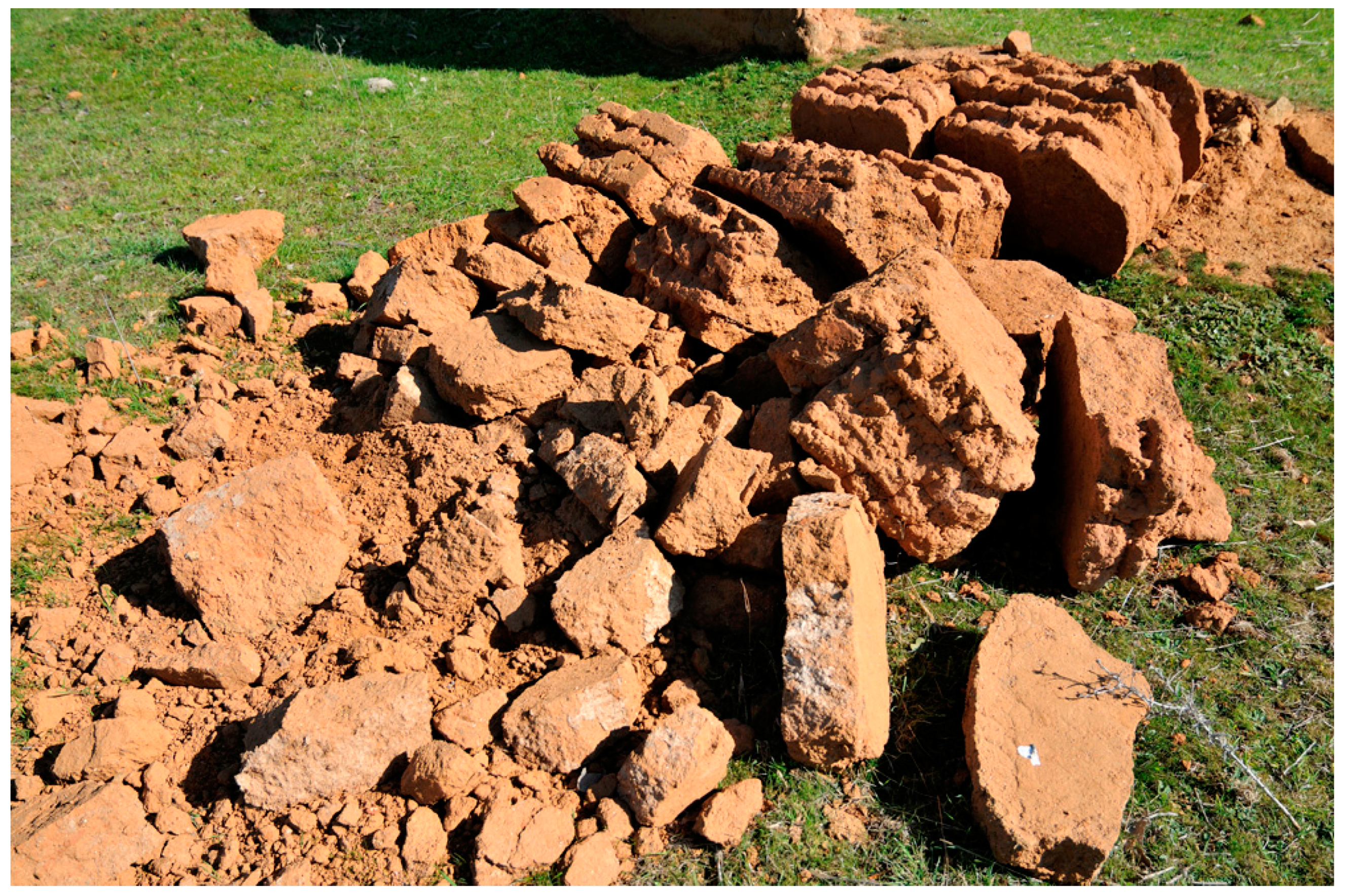
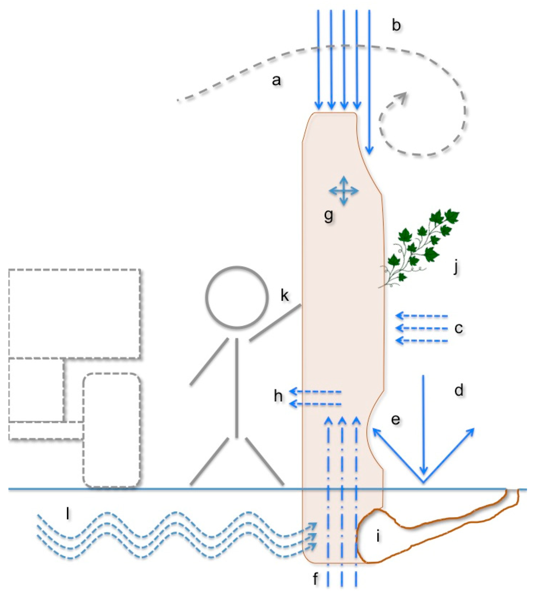
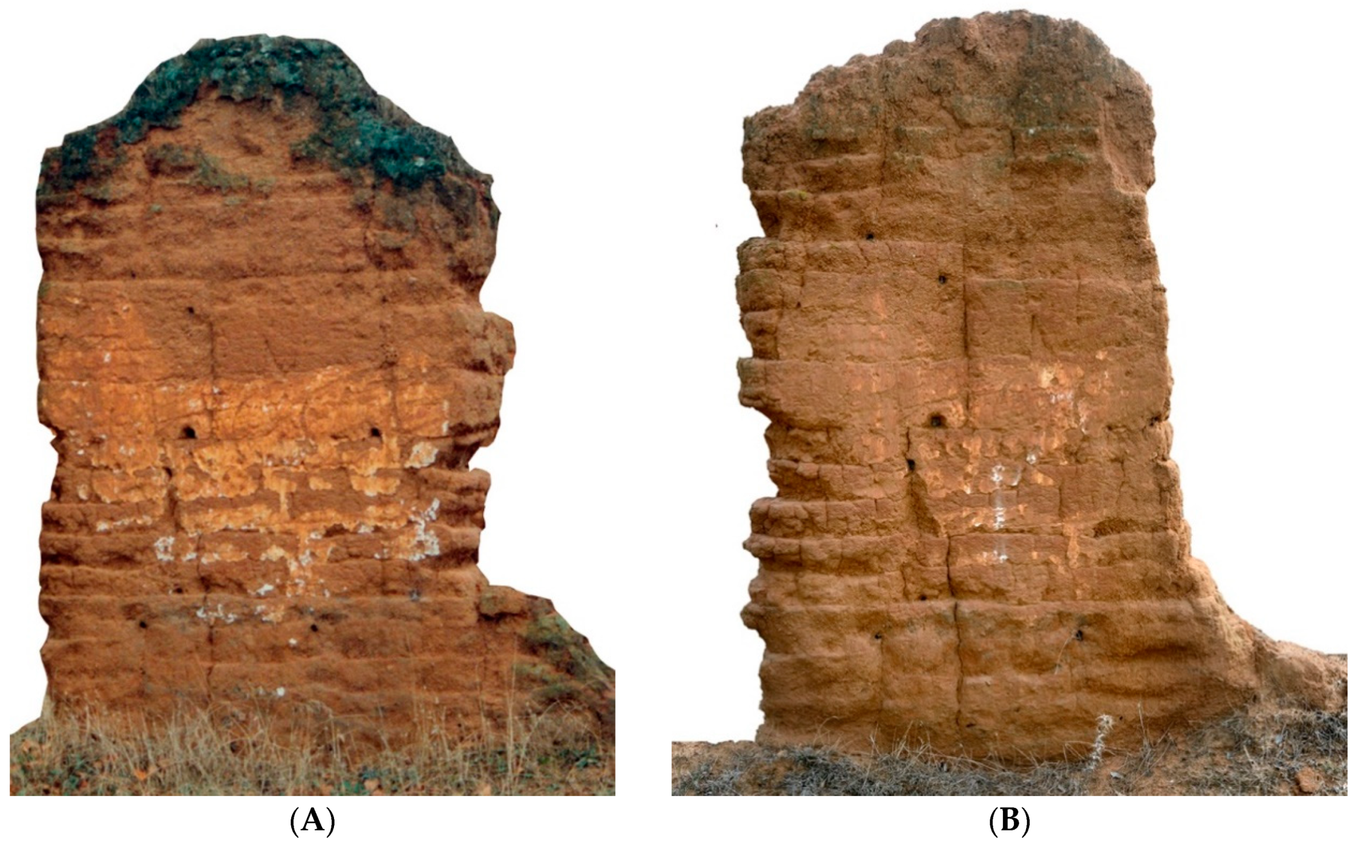
3. General Patterns of Decay of Unreinforced Rammed Earth and Adobe Walls
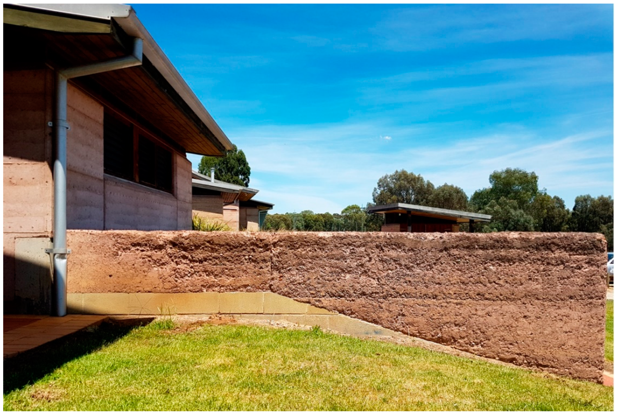
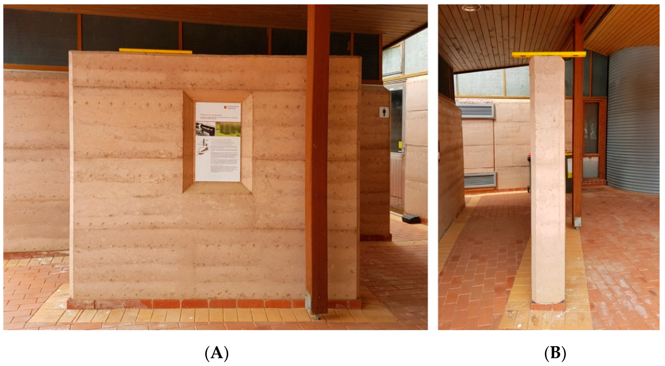
4. Modern Decay at Thurgoona (NSW)
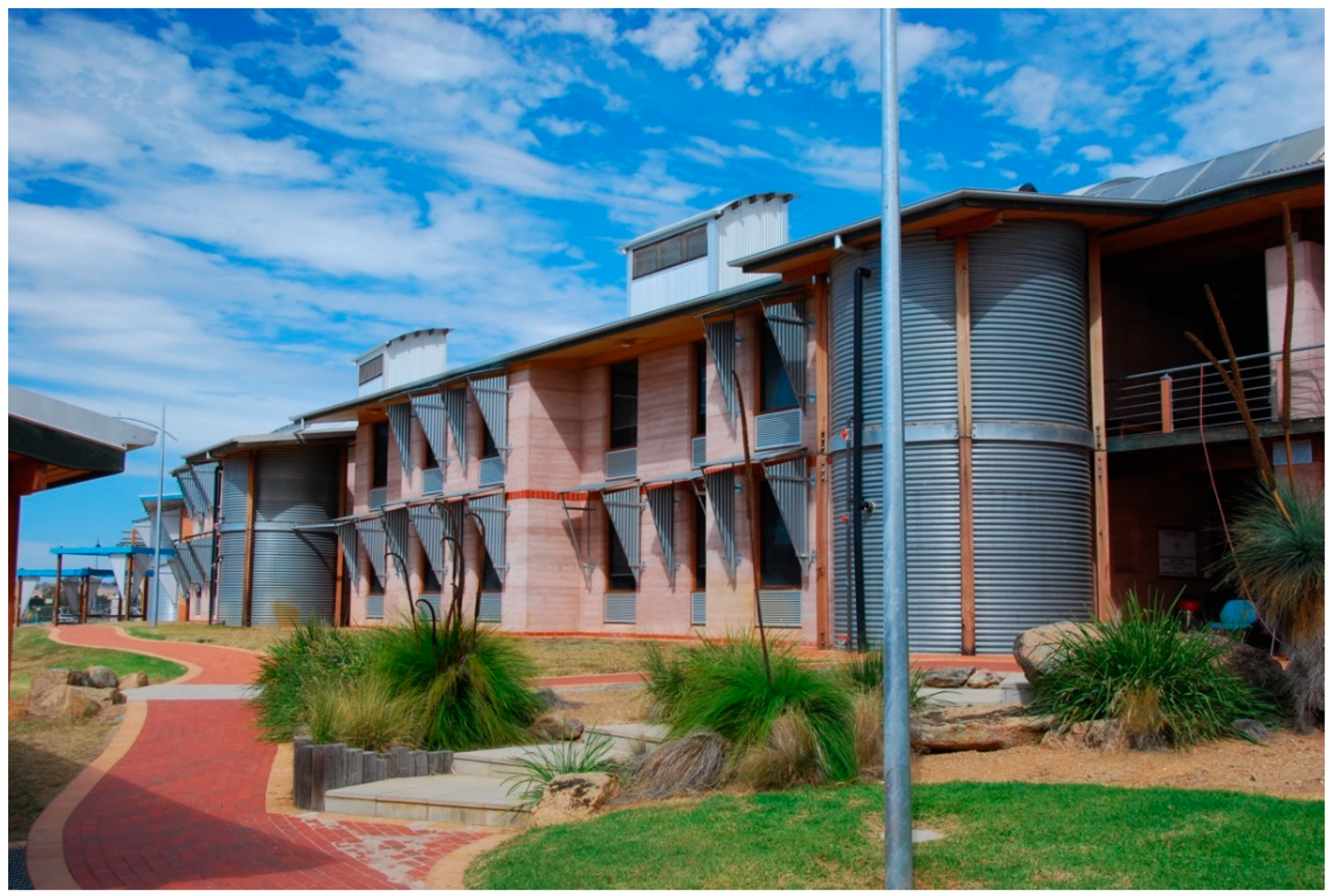
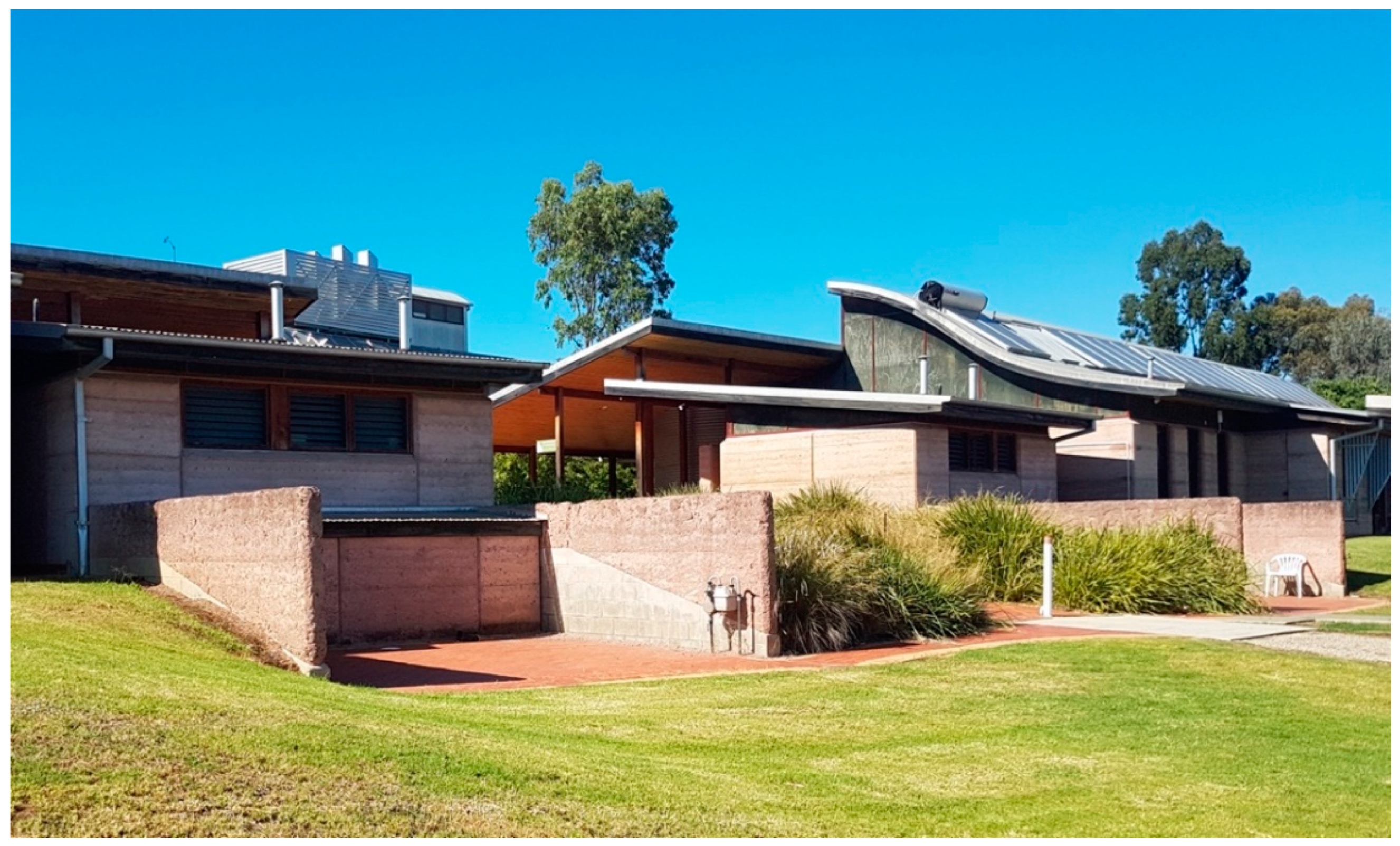
4.1. The Construction of Buildings 760, 761, and 762 at Thurgoona
4.2. General Observations of Decay
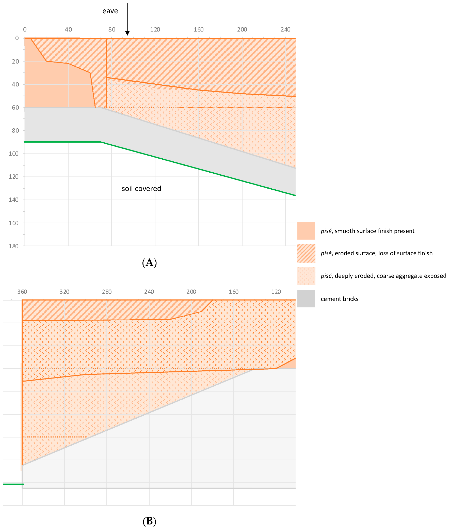
4.3. Results of Decay Measurements and Observations
- (i).
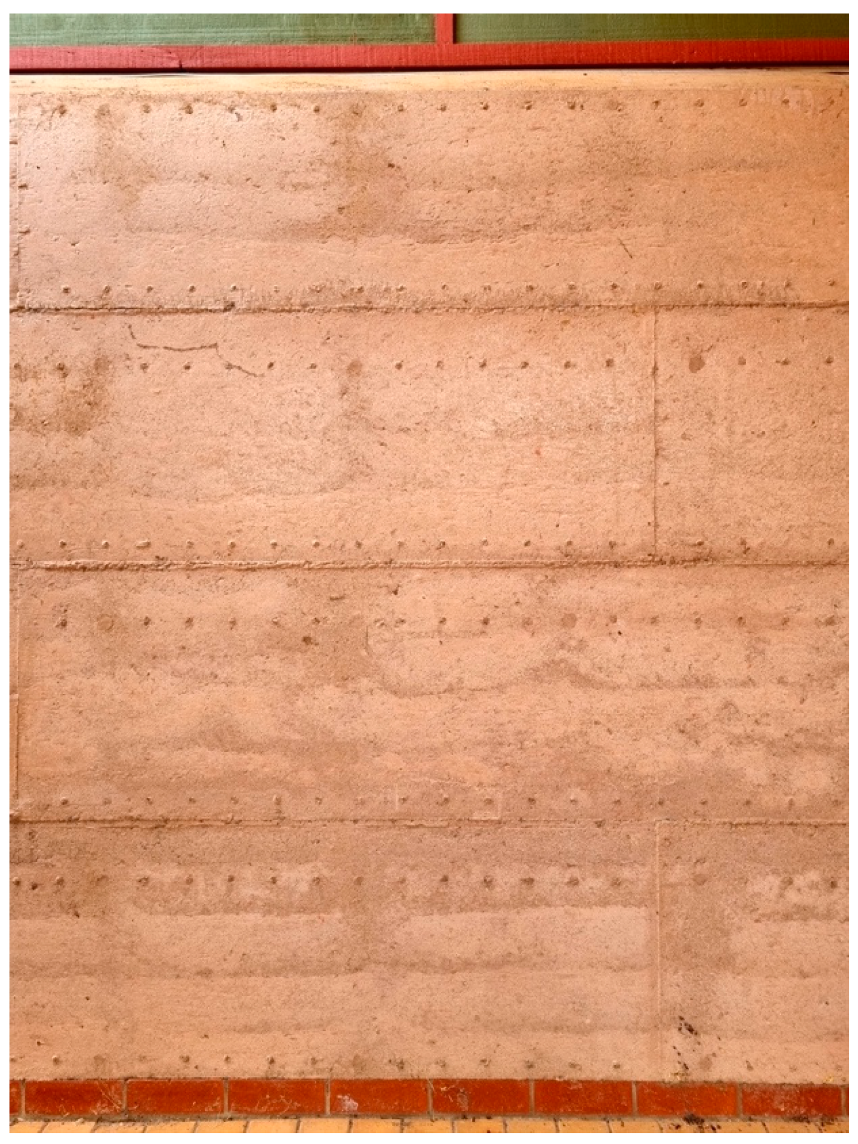
- An original surface with a rougher texture and some loss of detail compared to the surfaces of the control walls that are roofed and protected from the environment.
- (ii).
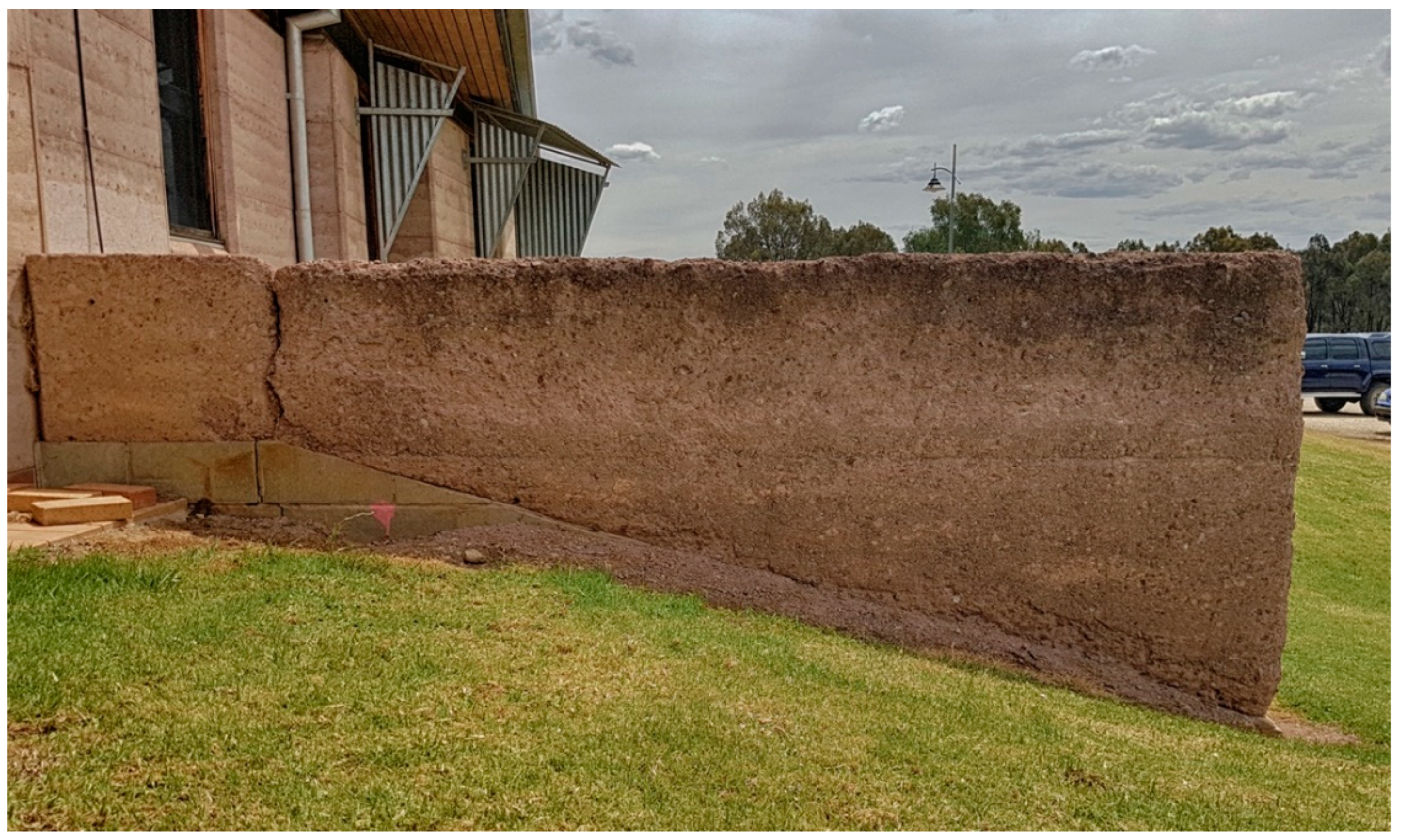
- Surfaces that show pitting and general loss of finish, resulting in a coarse-textured surface revealing the nature of the aggregate. The top of the wall is eroding and loses definition, exposing the aggregate.
- (iii).
- Below-surface separation of the external skin from the core, resulting in bulging of the exterior and noticeable ‘drumminess’.
- (iv).
- Surfaces where the original skin has spalled off, resulting in a very uneven and very coarse textured fabric, exposing the aggregate. The top of the wall has become rounded.
- (v).
- Continued deep erosion.
4.4. Ancillary Observations
5. Discussion
6. Conclusions
7. Implications
Funding
Institutional Review Board Statement
Informed Consent Statement
Data Availability Statement
Acknowledgments
Conflicts of Interest
References
- Boltshauser, R.; Veillon, C.; Maillard, N. Pisé. Stampflehm–Tradition und Potenzial; Triest: Zürich, Switzerland, 2019. [Google Scholar]
- Güntzel, J.G. Zur Geschichte des Lehmbaus in Deutschland. 1. Massive Lehmbauten: Geschichte, Techniken, Verbreitung; Ökobuch-Verlag: Rastede, Germany, 1988. [Google Scholar]
- Morgan, W.N. Earth Architecture: From Ancient to Modern; University Press of Florida: Gainesville, FL, USA, 2008. [Google Scholar]
- Maher, J.; Madrigal, J. Earth Architecture in Rural Egypt: Challenges of the context and the material. A+ Arch Des. Int. J. Archit. Des. 2021, 7, 99–112. [Google Scholar]
- Macdonald, K.C.; Morgan, D.W. African earthen structures in colonial Louisiana: Architecture from the Coincoin plantation (1787–1816). Antiquity 2012, 86, 161–177. [Google Scholar] [CrossRef][Green Version]
- Ruiz, D.; López, C.; Unigarro, S.; Domínguez, M. Seismic rehabilitation of sixteenth-and seventeenth-century rammed earth–built churches in the Andean highlands: Field and laboratory study. J. Perform. Constr. Facil. 2015, 29, 04014144. [Google Scholar] [CrossRef]
- Hallock, G. Pisé construction in early nineteenth-century Virginia. Perspect. Vernac. Archit. 2004, 11, 40–53. [Google Scholar]
- Spennemann, D.H.R. Managing the heritage of German-style mud and pine buildings in Australia. In Keller, Klöster und Kataster. Festschrift zum 30-Jährigen Bestehen der Bodendenkmalpflege Neuss; Striewe, K., Ed.; Neusser Schriften zur Archäologie und Bodendenkmalpflege; Stadt Neuss: Neuss, Germany, 2021; Volume 1, pp. 79–88, in press. [Google Scholar]
- Spennemann, D.H.R. Diachronic Observations of the Decay of a Pisé Building at Jugiong (NSW); Institute for Land, Water and Society, Charles Sturt University: Albury, NSW, Australian, 2015. [Google Scholar]
- Spennemann, D.H.R. Callitris and Mud. An Analysis of the Construction and Decay of a German Farmhouse Complex at Edgehill near Henty (NSW); Institute for Land, Water and Society, Charles Sturt University: Albury, NSW, Australian, 2015. [Google Scholar]
- Spennemann, D.H.R. Echoes of the Past. Visions of the Future. The German Colonial Experience in Australia. A Travelling Exhibition; Retrospect: Albury, NSW, Australian, 2009. [Google Scholar]
- Archer, J.; Archer, G. Dirt Cheap. The Mud Brick Book; Second Back Row Press, Compendium Pty: Melbourne, Australian, 1976. [Google Scholar]
- Sameh, S.H. Promoting earth architecture as a sustainable construction technique in Egypt. J. Clean. Prod. 2014, 65, 362–373. [Google Scholar] [CrossRef]
- Hall, M.R.; Lindsay, R.; Krayenhoff, M. Modern Earth Buildings: Materials, Engineering, Constructions and Applications; Elsevier: Amsterdam, The Netherlands, 2012. [Google Scholar]
- Dobson, S. Rammed earth in the modern world. In Rammed Earth Construction Cutting-Edge Research on Traditional and Modern Rammed Earth; Ciancio, D., Beckett, C., Eds.; CRC Press: London, UK, 2015; pp. 3–10. [Google Scholar]
- Guillaud, H. Markers of Earthen Construction Modern Revival. In Proceedings of the Vernacular and Earthen Architecture: Conservation and Sustainability Proceedings of SosTierra 2017, Valencia, Spain, 14–16 September 2017; pp. 3–8. [Google Scholar]
- Piani, T.L.; Weerheijm, J.; Koene, L.; Sluys, L. Safe Use of Sustainable Building Materials: A reappraisal of Adobe. In Proceedings of the ICSBM 2019. 2nd International Conference of Sustainable Building Materials, Eindhoven, The Netherlands, 12–15 August 2019; p. 306. [Google Scholar]
- Webster-Mannison, M. Integrated systems with rammed earth: Charles sturt university, Thurgoona campus, New South Wales, Australia. In Alternative Construction: Contemporary Natural Building Methods; Elizabeth, L., Adams, C., Eds.; John Wiley & Sons: Hoboken, NJ, USA, 2000; pp. 273–282. [Google Scholar]
- Webster-Mannison, M. Cooling rural Australia. EcoLibrium 2003, 1, 22–26. [Google Scholar]
- Lindsay, R. Australian modern earth construction. In Modern Earth Buildings; Elsevier: Amsterdam, The Netherlands, 2012; pp. 609–649. [Google Scholar]
- Illampas, R.; Ioannou, I.; Charmpis, D.C. Overview of the pathology, repair and strengthening of adobe structures. Int. J. Archit. Herit. 2013, 7, 165–188. [Google Scholar] [CrossRef]
- Velosa, A.; Varum, H.; Sáez, M. Characterization of Adobe Blocks from Burgos. In Proceedings of the 9º SIACOT, Seminário Ibero-Americano de Construção e Arquitectura com Terra/6º ATP, Seminário de Arquitectura de Terra em Portugal, Coimbra, Portugal, 20–23 February 2010; pp. 20–23. [Google Scholar]
- Dal, M.; Ergin, Ş. Alterations Seen in Adobe Structures. In Proceedings of the Kerpic’19–Earthen Heritage, New Technology, Management 7th International Conference, Köycegiz, Turkey, 5–7 September 2019. [Google Scholar]
- Silva, R.A.; Mendes, N.; Oliveira, D.V.; Romanazzi, A.; Domínguez-Martínez, O.; Miranda, T. Evaluating the seismic behaviour of rammed earth buildings from Portugal: From simple tools to advanced approaches. Eng. Struct. 2018, 157, 144–156. [Google Scholar] [CrossRef]
- Liang, R.; Stanislawski, D.; Hota, G. Material characterization and structural response under earthquake loads of hakka rammed earth buildings. Sustain. Struct. 2021, 1. Available online: https://par.nsf.gov/biblio/10297497 (accessed on 20 March 2022).
- Zawistowski, K.; Zawistowski, M.; Joffroy, T. Evolving Vernacular: Reinventing Rammed Earth in the Context of Twenty-First Century Seismic Regulation. Technol.|Archit. +Des. 2020, 4, 158–165. [Google Scholar] [CrossRef]
- Holub, M.; Stone, C.; Balintova, M.; Grul, R. Intrinsic Hydrophobicity of Rammed Earth. In Proceedings of the IOP Conference Series: Materials Science and Engineering, Leoben, Austria, 20–24 September 2015; p. 12024. [Google Scholar]
- Kebao, R.; Kagi, D. Integral admixtures and surface treatments for modern earth buildings. In Modern Earth Buildings; Elsevier: Amsterdam, The Netherlands, 2012; pp. 256–281. [Google Scholar]
- Stazi, F.; Nacci, A.; Tittarelli, F.; Pasqualini, E.; Munafò, P. An experimental study on earth plasters for earthen building protection: The effects of different admixtures and surface treatments. J. Cult. Herit. 2016, 17, 27–41. [Google Scholar] [CrossRef]
- Bureau of Meteorology. Climate Statistics for Australian Locations. Monthly Climate Statistics. Albury Airport. Available online: http://www.bom.gov.au/climate/averages/tables/cw_072146_All.shtml (accessed on 12 January 2022).
- de Teel Tiller, P.; Look, D.W. Preservation of Adobe Buildings. Preservation Briefs; Preservation Assistance Division, U.S. National Park Service, U.S. Department of the Interior: Washington, DC, USA, 1978; Volume 5.
- Guillaud, H. “Pisé”: Evolution, innovations, resistances and future directions. In Rammed Earth Conservation; Mileto, C., Vegas, F., Cristini, V., Eds.; CRC Press Balkema: London, UK, 2012; pp. 3–9. [Google Scholar]
- Hall, M.; Djerbib, Y. Moisture ingress in rammed earth: Part 1—The effect of soil particle-size distribution on the rate of capillary suction. Constr. Build. Mater. 2004, 18, 269–280. [Google Scholar] [CrossRef]
- Hall, M.; Djerbib, Y. Moisture ingress in rammed earth: Part 2—The effect of soil particle size distribution on the absorption of static pressure-driven water. Construction and Building. Constr. Build. Mater. 2006, 20, 374–383. [Google Scholar] [CrossRef]
- Hall, M.; Djerbib, Y. Moisture ingress in rammed earth: Part 3—Sorptivity, surface receptiveness and surface inflow velocity. Constr. Build. Mater. 2006, 20, 384–395. [Google Scholar] [CrossRef]
- Anonymous. Pise, or clay buildings. The Australian Town & Country Journal (Sydney), 12 March 1870; 16. [Google Scholar]
- Anonymous. Pise or clay buildings. The Australian Town & Country Journal (Sydney), 11 November 1871; 621. [Google Scholar]
- Anonymous. On building with earth of pise. The Australian Town & Country Journal (Sydney), 10 May 1873; 11. [Google Scholar]
- Anonymous. Building in pisé. The Australian Town & Country Journal (Sydney), 20 May 1876; 817. [Google Scholar]
- Anonymous. Pisé Buildings. Their construction and suitability. Australian Town & Country Journal (Sydney), 26 November 1892; 30. [Google Scholar]
- Anonymous. Pise Buildings. Albury Banner, 13 August 1897; 13. [Google Scholar]
- Anonymous. Pise Walls. Albury Banner, 19 November 1897; 13. [Google Scholar]
- Anonymous. On Building in Pise. Albury Banner, 24 January 1902; 12. [Google Scholar]
- Anonymous. Pisé Buildings. Their construction and suitability. Australian Town and Country Journal, 10 February 1904; 26. [Google Scholar]
- Rirsch, E.; Zhang, Z. Rising damp in masonry walls and the importance of mortar properties. Constr. Build. Mater. 2010, 24, 1815–1820. [Google Scholar] [CrossRef]
- Spennemann, D.H.R. Mitigation of salt damage to the historic built environment. In PUR$L Productive Use and Rehabilitation of Saline Land. Managing Saltland into the 21st Century: Dollars and Sense from Salt; Marcar, N.E., Afzal Hossain, A.K.M., Eds.; National Committee for the Productive Use and Rehabilitation of Saline Land: Canberra, Australia, 1999; pp. 13–19. [Google Scholar]
- Spennemann, D.H.R.; Marcar, N.E. Urban and heritage landscapes. Under the saline threat. Nat. Resour. Manag. 1999, 2, 14–17. [Google Scholar]
- Spennemann, D.H.R. Urban Salinity as a Threat to Cultural Heritage Places. A Primer on the Mechanics and Effects of Chloridation; Johnstone Centre of Parks, Recreation and Heritage, Charles Sturt University: Albury, NSW, Australia, 1997. [Google Scholar]
- Allen, D.; Sanchez, G.; Hill, J. The effects of the Loma Prieta earthquake on the seismically retrofitted Santa Cruz Mission Adobe. In The Seismic Retrofit of Historic Buildings Conference Workbook 1991; Look, D.W., Ed.; Western Chapter of the Association of Preservation Technology: San Francisco, CA, USA, 1991; pp. 8/1–8/7. [Google Scholar]
- Green, M.; Watson, A. Sesimic rehabilitation of the Parra Adobe. In The Seismic Retrofit of Historic Buildings Conference Workbook 1991; Look, D.W., Ed.; Western Chapter of the Association of Preservation Technology: San Francisco, CA, USA, 1991; pp. 23/21–23/26. [Google Scholar]
- Tolles, E.L.; Webster, F.A.; Thiel, C.C.; Kimbro, E.E.; Ginell, W.S. Recent developments in understanding the seismic performance of historic adobe buildings. In The Seismic Retrofit of Historic Buildings Conference Workbook 1991; Look, D.W., Ed.; Western Chapter of the Association of Preservation Technology: San Francisco, CA, USA, 1991; pp. 7/1–7/32. [Google Scholar]
- AS 2121-1979; The Design of Earthquake Resistant Buildings. Standards Australia: Sydney, Australia, 1979.
- AS 1170.4-2007; Structural Design Actions Part 4: Earthquake Actions in Australia. Standards Australia: Sydney, Australia, 2007.
- Burbidge, D.R. The 2012 Australian Earthquake Hazard Map. Record 2012/071; Geoscience Australia: Canberra, Australia, 2012. [Google Scholar]
- Leonard, M.; Burbidge, D.; Edwards, M. Atlas of Seismic Hazard Maps of Australia. Record 2013/041; Geoscience Australia: Canberra, Australia, 2013. [Google Scholar]
- Spennemann, D.H.R. The Effects of the 1871–72 Earthquakes on the Southern Riverina. An Overview of Historical and Anecdotal Data; The Johnstone Centre, Charles Sturt University: Albury, NSW, Australia, 1998. [Google Scholar]
- Spennemann, D.H.R. Effects of earthquakes on Wagga Wagga: The 1871 and 1872 events. Bull. Wagga Wagga Hist. Soc. 1996, 300, 3–6. [Google Scholar]
- Webster-Mannison, M. Greening of a University Campus. In Proceedings of the Shaping the Sustainable Millennium-Collaborative Approaches Conference, Brisbane, Australia, 5–7 July 2000. [Google Scholar]
- Howard, J.; Mitchell, D.S.; Spennemann, D.H.R.; Webster-Mannison, M. Is today shaping tomorrow for tertiary education in Australia? a comparison of policy and practice. Int. J. Sustain. High. Educ. 2000, 1, 83–96. [Google Scholar]
- Mitchell, D.S.; Croft, I.; Harrison, T.; Webster-Mannison, M. Water Management on the Thurgoona Campus of Charles Sturt University. In Proceedings of the On-Site ’01 Conference: Advancing On-Site Wastewater Systems, Armidale, Australia, 25–27 September 2001; pp. 287–294. [Google Scholar]
- Mitchell, D.S.; Webster-Mannison, M. Management of Water Resources: Pilot Project for Integrated Waste Management Systems. Technical Report. Thurgoona Campus, Charles Sturt University; Charles Sturt University: Albury, NSW, Australia, 1998. [Google Scholar]
- Taylor, P.; Fuller, R.; Luther, M. Validated Model and Study of a Rammed Earth Wall building. In Proceedings of the ANZSES 2004: Solar 2004: Life, the Universe and Renewables, Perth, Australia, 30 November–3 December 2004. [Google Scholar]
- Taylor, P.A. Energy and Thermal Comfort in a Rammed Earth Office Building; Deakin University: Geelong, Australia, 2005. [Google Scholar]
- Johnston, L. Deep Green: Charles Sturt University, Thurgoona Campus, NSW. Archit. Rev. Aust. 2000, 73, 94–99. [Google Scholar]
- Spennemann, D.H.R. From Retrospectivity to Strategic Foresight. Towards a paradigm shift in Cultural Heritage Management [Poster]. 2007. [Google Scholar] [CrossRef]
- O’Halloran, C. City of Albury–City Wide Heritage Study; Albury City Council: Albury, Australia, 2004. [Google Scholar]
- Minister for Planning. Albury Local Environmental Plan 2010 under the Environmental Planning and Assessment Act 1979 NSW; Minister for Planning: Sydney, Australia, 2010; Volume 2010/433. Available online: https://legislation.nsw.gov.au/view/whole/html/inforce/current/epi-2010-0433 (accessed on 20 March 2022).
- Webster-Mannison, M.; McInerney, C. Charles Sturt University Thurgoona Campus Development Application Report; Division of University Properties, Charles Sturt University: Bathurst, Australia, 1998. [Google Scholar]
- AS 1141.51—1996; Methods for Sampling and Testing Aggregates. Method 51: Unconfined Compressive Strength of Compacted Materials. Standards Australia: Sydney, Australia, 1996.
- AS 1289.3.1.1—1995; Methods of Testing Soils for Engineering Purposes. Method 3.1.1: Soil Classification Tests—Determination of the Liquid Limit of a Soil—Four Point Casagrande Method. Standards Australia: Sydney, Australia, 1995.
- AS 1289.3.2.1—1995; Methods of Testing Soils for Engineering Purposes. Method 3.2.1: Soil Classification Tests—Determination of the Plastic Limit of a Soil—Standard Method. Standards Australia: Sydney, Australia, 1995.
- AS 1289.3.3.1—1995; Methods of Testing Soils for Engineering Purposes. Method 3.3.1: Soil Classification Tests—Calculation of the Plasticity Index of a Soil. Standards Australia: Sydney, Australia, 1995.
- AS 1289.3.4.1—1995; Methods of Testing Soils for Engineering Purposes. Method 3.4.1: Soil Classification Tests—Determination of the Linear Shrinkage of a Soil Standard Method. Standards Australia: Sydney, Australia, 1995.
- AS 1289.3.6.1—1995; Methods of Testing Soils for Engineering Purposes. Method 3.6.1: Soil Classification Tests—Determination of the Particle Size Distribution of a Soil—Standard Method of Analysis by Sieving. Standards Australia: Sydney, Australia, 1995.
- AS 1289.5.2.1—1995; Methods of Testing Soils for Engineering Purposes. Method 5.2.1: Soil Compaction and Density Tests—Determination of the Dry Density/Moisture Content Relation of a Soil Using Modified Compactive Effort. Standards Australia: Sydney, Australia, 1995.
- AS 3972—1997; Portland and Blended Cements. Standards Australia: Sydney, Australia, 1997.
- McInerney, C. Thurgoona Campus. Specification for Student Association Faciliities, Rammed Earth; Office of Design, Charles Sturt University: Wagga Wagga, Australia, 2001. [Google Scholar]
- McInerney, C. Thurgoona Campus. Specification for School of Business, 4–Rammed Earth; Office of Design, Charles Sturt University: Wagga Wagga, Australia, 2003. [Google Scholar]
- Middleton, G.F.; Schneider, L.M. Earth-Wall Construction; National Building Technology Centre: Chatswood, NSW, Australia, 1987.
- Tech-Dry Building Protection Systems. Tech-Dry Plasticure RPKR2. 2022. Available online: https://www.techdry.com.au/wp-content/uploads/2018/08/Plasticure-PDS-1.pdf (accessed on 22 January 2022).


| Date | Event | Building (n°) |
|---|---|---|
| 1993 | Charles Sturt University acquires the site | |
| 1995–1996 (May) | Student Pavilion Building | 672 |
| 1997–1999 (Feb) | School of Environmental (and Information) Sciences Offices | 760 |
| 1997–1999 (Feb) | Specialist teaching building (and computer lab) | 761 |
| 1997–1999 (Feb) | Office building, a regional herbarium | 762 |
| 1998 | Network facility completed (telephone and computer switch) | 754 (part) |
| 1998–2000 | Four eight-room student cottages and laundry block | 680–684 |
| 1998 (Oct)–2001 | Two-story teaching complex, including a 200-seat lecture theatre. | 751 |
| 2001–2002 (Feb) | Two additional eight-room student cottages | 685–686 |
| 2002–2003 (Jul) | Student Recreation Facility | 752 |
| 2004 (Feb)–2005 (Jun) | School of Early Childhood Education Offices | 763 |
| Constituent Materials | |
|---|---|
| Soil particle sizes | |
| Organic content | <2% |
| Clay and silt content | <20% |
| Sand content | ≥50% |
| Coarse aggregate content | >30% |
| Water | Clean, fresh, free from impurities |
| Stabilizing agent | Cement (AS 3972) GP grade |
| Stabilized earth mix at placement | |
| Cement content (range) | max. 5% by weight |
| Adj. compressive strength (min.) | 2.5 MPa |
| Moisture content (range) | 8–16% |
| Dry density (t/m3) | 2.13 |
| Liquid limit (max.) | 35% |
| Plastic limit (max.) | 20% |
| Plasticity index (max.) | 12% |
| Linear shrinkage (max.) | 5% |
| Plasticity index: linear shrinkage | 2.5:1 |
Publisher’s Note: MDPI stays neutral with regard to jurisdictional claims in published maps and institutional affiliations. |
© 2022 by the author. Licensee MDPI, Basel, Switzerland. This article is an open access article distributed under the terms and conditions of the Creative Commons Attribution (CC BY) license (https://creativecommons.org/licenses/by/4.0/).
Share and Cite
Spennemann, D.H.R. Earth to Earth: Patterns of Environmental Decay Affecting Modern Pisé Walls. Buildings 2022, 12, 748. https://doi.org/10.3390/buildings12060748
Spennemann DHR. Earth to Earth: Patterns of Environmental Decay Affecting Modern Pisé Walls. Buildings. 2022; 12(6):748. https://doi.org/10.3390/buildings12060748
Chicago/Turabian StyleSpennemann, Dirk H. R. 2022. "Earth to Earth: Patterns of Environmental Decay Affecting Modern Pisé Walls" Buildings 12, no. 6: 748. https://doi.org/10.3390/buildings12060748
APA StyleSpennemann, D. H. R. (2022). Earth to Earth: Patterns of Environmental Decay Affecting Modern Pisé Walls. Buildings, 12(6), 748. https://doi.org/10.3390/buildings12060748