1. Introduction
Over the past few decades, conventional strengthening methods, such as the use of externally bonded steel plates, have been facing serious difficulties; hence, fiber-reinforced polymers (FRPs) have shown suitable performance for such purposes [
1,
2,
3]. The use of FRP composites to reinforce and repair historical as well as concrete structures has been accordingly considered by many researchers thanks to its advantages [
4,
5,
6]. In fact, fiber reinforcement plays a substantial role in strengthening structural elements, especially in altering brittleness [
7]. In this sense, FRPs are much more attractive in civil engineering and the construction industry owing to their unique benefits [
8,
9,
10], including weight resistance, corrosion resistance, high ductility, simple and high-speed implementation, and excellent adhesion to masonry substrates. FRP composites have also been utilized to attach to the surface of some elements via organic matrix-like epoxy resins [
11,
12]. In spite of their many advantages, a series of defects in such polymers have been similarly observed, i.e., difficulty in use at low temperatures, no use on wet surfaces, differences in materials applied between epoxy resins and concrete substrates, working hazards, thermal compatibility problems, different thermal coefficients between epoxy resins and material substrates, no fire resistance at high temperatures, the cost of epoxies, low glass (G) transition temperature, and insufficient vapor permeability [
13,
14]. As a result, poor bonds have often given rise to the premature delamination of epoxy resins as substrates [
15,
16].
To deal with the problems in utilizing the organic matrix, researchers have been trying to find other ways to replace epoxy resins through inorganic forms, such as a similar genus with concrete substrates [
17]. Inorganic matrix can be thus suggested at low temperatures and into wet surfaces since it accepts vapor permeability and has a better heat resistance and lower costs compared with epoxy resins. In general, the novel pattern of reinforcements has been recently introduced with the aim to increase performance and minimize total product costs. Furthermore, textile-reinforced concrete (RC), in comparison with the well-known FRP, carries unique advantages such as being light-weight, fast in the application, easy to handle, and cheap [
18,
19,
20].
The FRCM system, an inorganic matrix, has been presented as a stable and durable replacement instead of FRPs (such as epoxy resins) to meet their disadvantages and shortcomings. Meanwhile, several names have been suggested thus far, including FRCM, textile-reinforced mortar (TRM), and textile-reinforced cementitious (TRC). The FRCM system contains the supplies with dry fiber mesh in two orthogonal directions. Similarly, fabric composites are buried in a mortar-based layer of cement. In recent research regarding the improved performance of FRCM, especially in terms of mesh adhesion, a unique grid has also been designed to penetrate mortar grains well into the fabric and result in a strong lock that prevents impermeable or fracture failure [
21]. To increase the functionality of the FRCM system, several types of fiber Gs have also been used, such as polypropylene (PP), polyethylene (PE), and polyoxymethylene (POM). In this regard, POM has more engineering applications, and its mechanical properties are more appropriate than PP and PE. In similar research, carbon (C), G, basalt, steel, and recently polyparaphenylene benzobisoxazole (PBO) have been further utilized. It is of utmost importance to mention that the FRCM system has even been improved by ultra-high mesh (UHM), especially PBO, whose mechanical properties have been enhanced compared with C fiber. Moreover, PBO can have a significant impact on energy absorption capacity, high friction, fire resistance, and compatibility. Additionally, they have been used for some samples in several studies [
22,
23,
24].
Some research has been conducted and published as review papers on the upgrading of structural elements [
7,
11,
25], focusing mostly on strengthening steel structures and concrete structures using FRP systems. However, the behavior of FRP differs from that of FRCM systems, particularly at high temperatures and ultimate strength. Although a hybrid combination of CFRP and BFRP was proposed for strengthening structural beams at high temperatures, not many details are reported about this issue [
8]. First, the expected cost was not argued. Second, it was unclear how successful the proposed reinforcement would be in various temperature ranges. High temperatures can alter the conventional failure modes, and only limited research has been conducted on this topic to accurately evaluate the performance of FRCM for the strengthening of concrete members during temperature change [
4,
26].
Alabdulhady et al. [
27] investigated the torsional strengthening of RC beams using FRCM composites and reported a series of details regarding strengthening methods (including the type of composite, the number of textile layers, wrapping, and modes of failure), reinforcement configuration, and anchorage systems. However, there are a few shortcomings in this study, e.g., the effects of temperature and type of matrix (different mortars were not studied). Koutas et al. [
16] provided a literature review on the tensile and bond response of FRCM systems, as well as flexure and shear strengthening, with an emphasis on seismic strengthening. However, no design formulations were provided in their study. The present study begins with a review of previous research on structural elements retrofitted with the FRCM system and further proposes a design formula that takes into account various parameters, such as layers, composite types, configurations, and anchors, to control or delay FMs. In fact, the FRCM systems exhibit better performance at high temperatures compared with FRPs and even decrease the length of cracks in strengthened specimens. Furthermore, a comprehensive dataset was collected from different elements, including beams, walls, slabs, and arches. Afterwards, the results are depicted in the ratio of load-carrying capacity to the number of layers and type of composite curves, in the forms of beam and column, taking into account various failure modes of slippage, fiber rupture, delamination, debonding, and crack for flexural and shear behavior of beams and their failure modes, including slippage, fiber rupture, telescopic failure, and debonding for the column. For other members, findings are analyzed and discussed using the ratio of load-carrying capacity to the type of composite curves with respect to their failure modes. Overall, this paper reflects on the relationship between composite types and layers against FMs in various structural elements. This can be utilized as a benchmark example in future studies, as there is no such basis available in the literature, to the best of the authors’ knowledge.
3. Reducing the Catastrophic Effect of FMs on Beams Subjected to Different Behaviors
Following the catastrophic damage caused by the gas explosion in the Ronan Point tower [
29], several government agencies and international code writers sought to improve guidelines and recommendations to mitigate or prevent the potential for such catastrophic collapses. In addition, due to extra loads, environmental factors, cracks, and deficiencies in designing and implementing concrete structures, rehabilitation is more often vital rather than reconstruction for concrete members [
30]. Hence, a series of research studies have been fulfilled on beams strengthened with the FRCM system and the effect of various parameters, including the type of FRCM systems (i.e., C, basalt, PBO, and G), configurations (viz. full-, U-, and W-wrapping), surface textiles (that is, uncoated and coated), the number of layers, the type of matrix (namely, cement, and resin), anchors (i.e., composite, mechanical, near-surface, and externally bonded), the effect of fiber orientation (i.e., 45° and 90°), the impact of high temperatures, the type of mortars, the effect of corrosion, the impact of fatigue, the effect of internal steel reinforcement, and the impact of value fabric, have been so far investigated, whose results in this line are reported in the following sections. Meanwhile, different methods for beam strengthening are presented in
Figure 2. As seen, four different flexural strengthening methods of beams with the FRCM system are depicted under flexural loading, namely full wrapping, U-wrapping, U-wrapped at the end of FRCM, and discontinued wrapping.
3.1. Flexural Behavior
The application of externally bonded composite materials increases the load-carrying capacity in the case of the bending strength of RC structural elements [
31,
32,
33]. The effectiveness of the FRCM systems as flexural retrofitting materials for RC structures has also been investigated, so the significant aspects of structural elements with composite materials are reviewed in this research study. The use of U-wrapping and side-activated surface bonding methods have also been suggested to control debonding [
34]. Debonding depends on a variety of parameters, such as crack distance length, the geometry of the beam, the bending moment of the beam, and the arrangement of reinforcing bars. In fact, debonding began with intermediate flexural cracks in the constant moment region. Pino et al. [
35] investigated the performance of strengthened beams utilizing FRCM systems subjected to fatigue. The results indicate that by increasing the number of layers from 1 to 3, failure modes shifted from the fabric-matrix slip to abrupt debonding of the FRCM, with a 0.17% increase in maximum load.
To study the effect of the number of textile layers, the bond-stiffness coefficient (BSC) was first introduced by Elsanadedy et al. [
36] as the ratio between the TRM stiffness and the tensile bond strength. On the basis of numerical methods,
Table 3 illustrates the adequacy of the number of textile layers calculated from Equation (1). In general, the number of textile layers is ideal whenever the effective strain of the textile reinforcement is restricted to the strain level at which debonding takes place.
where
is the BSC,
n refers to the number of the TRM layers,
shows the tensile module of the fiber in MPa,
represents the equivalent smeared thickness of one layer in mm, and
NFLS shows the tensile bond strength in MPa [
36].
When the number of the textile layers is augmented, it contributes to enhancing the fatigue life of the retrofitted beams. The results reveal that increasing the number of layers from 1 to 3 can lead to improved fatigue life of the load capacity in the flexural strengthening by 32–58% [
37]. In addition, enlarging the number of the TRM layers from 1 to 3 boosts the flexural and load-carrying capacity, and even changes the fracture mechanism; however, the FRP layers do not experience this kind of enhancement due to premature failure, especially adhesive failure. By expanding the number of layers in FRPs from 1 to 3, the effectiveness factor becomes 0.47 and 0.80, respectively [
38,
39].
Based on the results of recent studies regarding the effect of the types of FRCM and surface textiles, the FRCM materials such as basalt have increased the flexural stiffness in beams, while the ductility in repaired RC beams has reduced. Textile G also plays a significant role in minimizing and controlling cracks in strengthened specimens with a G grid. For steel nets, the flexural capacity of retrofitted beams is also boosted with steel. Moreover, flexural stiffness elevates at all loading stages in steel nets, being the best material grid. Meanwhile, PBO yields the second-best outcomes. In the case of improving flexural capacity, they have lower ultimate flexural moments than the others. Additionally, C-FRCM is the best option to restore the system to develop flexural stiffness during the linear elastic step of loading [
13]. In this regard, Elghazy et al. [
40] demonstrated that strengthened beams had augmented flexural capacity in harsh environments. Beams repaired with PBO-FRCM also revealed a strength gain ranging from 7 to 44% compared with the control ones, while for the C-FRCM system, strength gain had been reported between 39 and 55%. It should be noted that the fracture mechanism was different for both of them. Considering the PBO-FRCM system, FRCM delamination and fabric slippage within mortars were the FMs, while premature matrix cracking had occurred in the C-FRCM system. Raoof and Bournas [
4] had similarly found that different fibers such as G, C, and coated basalt could have the same axial stiffness; however, flexural capacity did not follow the same trend. Coated basalt-fiber textile layers had further proved the highest flexural capacity as compared with other materials.
On the other hand, Alam et al. [
41] investigated a technique to delay debonding using typical anchorage systems because debonding was a premature failure, especially for composite materials. The effect of the strengthening configuration had also been taken into account, indicating that U-shaped anchorage at the end of the TRM layers was a suitable method for delaying the TRM end debonding [
36]. Based on the experimental texts, at the ends of the external flexural reinforcement, the U-jacket FRCM systems had precluded debonding failures between the strengthening materials and substrates [
42]. Two rehabilitation techniques, including U-shaped and single-sided ones, had also been studied for improving the fatigue life of the RC beams, suggesting that the single-sided rehabilitation method was much better for enhancing the fatigue life of RC beams [
37]. Elghazy et al. [
40] correspondingly showed that the theoretical formulations of the ACI-549.4R-13 did not consider the impact of continuous anchorage on delayed FM; hence, such formulations should be modified with an increase of 10% to assume the impact of the continuous U-shaped technique. In the case of TRM vs. FRP, it had been reported that TRM could slightly improve flexural capacity by about 9%, owing to the destruction mechanism compared with the FRP-strengthened beam, recorded as 90% [
38,
39].
In the case of strengthening configurations subjected to flexural behavior, some authors [
39,
43] investigated the FRCM U-shaped at the ends of beams (i.e., as an anchorage). Their findings indicate that this strengthening configuration system contributes significantly to delaying failure modes such as FRCM end debonding when compared to FRCM-strengthened beams without end bonding [
36]. On the other hand, although U-shaped anchorages do not necessarily enhance the effectiveness of the configuration systems in terms of load-carrying capacity, they do improve ductility and reduce unexpected failure modes [
14]. In addition, D’Ambrisi et al. [
44] indicated that there was no difference in failure modes for beams composed of continuous U-shaped strips and beams composed of U-shaped strips only at the beam ends, indicating that an increasing load-carrying capacity was represented by approximately 8% for beams composed of continuous U-shaped strips. Meanwhile, due to the high cost of FRCM, full wrapping or four-sided strengthening of beams with FRCM is neither common nor feasible. Similarly, there are a substantial number of eccentric structures, such as tunnel linings and calvers, which cannot be wrapped due to their shape, size, or other characteristics [
45].
3.1.1. FMs of Strengthened Beams under Flexural Behavior
According to Yin [
37], TRM could modify the fatigue destruction mechanism, and then the retrofitted beams could outperform the control ones. Furthermore, TRN could decrease the crack width in beams. As highlighted in recent research, the type of FRCM could determine the type of FM; for example, Elghazy et al. [
40] had reported that beams retrofitted with PBO-FRCM had failed by FRCM delamination and fabric slippage, whereas other specimens had failed by premature matrix cracking concerning the type of fiber, viz. C-FRCM. Based on the study conducted by Raoof et al. [
38,
39] regarding rehabilitation materials (namely, FRCM vs. FRP), the FMs of the FRCM system were fiber slippage, interlinear shear, and TRM debonding, while the FM as the adhesive failure had been recorded in the FRP-repaired specimens. According to the investigation by Raoof et al. [
38,
39] and Koutas et al. [
46,
47], two different FMs had been recorded, i.e., debonding from concrete substrates and fiber rupture in the constant moment zone in the FRP-strengthened beams. However, FMs could be classified into five groups, including textile surface fracture, roving slippage, TRM debonding, fiber rupture, and concrete cover peel-off. As a result, fracture mechanisms and FMs depended on the textile fiber materials, the number of TRM layers, and the textile surface. Considering the effect of temperature on FMs, it had also been noticed that TRM debonding with cover peel-off had been recorded in the TRM system at a temperature of more than 500 °C; whereas two categories of FMs in the FRP-retrofitted specimens had been observed, namely, cohesive failure at 50 °C and adhesive failure at the concrete-resin interface for 75, 100, and 150 °C.
According to the data available, five FMs strengthened with the FRCM system under flexural behavior were observed (
Figure 3a,b). Debonding accounted for 38% of FMs, while delamination was 4%, as shown in
Table 4. Therefore, debonding could occur in those strengthened with the FRCM system because FRCM debonding was followed by the externally bonded technique. In the cases of debonding failure, fiber rupture, and slippage, load-carrying capacity also increases upon a rise in the number of textile layers, while the type of failure mechanism does not change them.
Table 5 shows that the flexural crack is predominant on the FM in one textile layer, whereas debonding is much more common for two and three layers. On the other hand, the changes in the composite type have led to variations in the FMs based on the available data (
Figure 3b). This could be concluded by the fact that the mechanical properties of materials have a key role in determining failure mechanisms. In addition, in
Table 6, the percentage of the FMs is determined according to the composite type.
3.1.2. Theoretical Formulation
In order to design retrofitted with TRM, Equation (2) can be suitable for debonding failure, which occurs at the matrix subtract:
where
shows the debonding stress of the composite,
is the intermediate crack factor,
represents the matrix factor,
denotes the shape factor,
stands for the length,
is the elastic modulus of the composite,
indicates the equivalent thickness of the textile,
depicts the concrete compressive strength,
refers to the shape factor, and
can be computed by Equation (2) [
38]. In the case of the debonding strain of the FRCM material by the fracture surface at the fiber-matrix interface, Equation (3) is presented:
where
is the debonding strain,
refers to the fracture energy,
stands for the number of textile layers,
represents the fabric thinness, and
shows the elastic modulus of the fiber [
14]. In order to investigate the safety of the retrofitted beams under a fatigue load, the ratio of the realistic stiffness to the computed one is expressed in Equation (4), and if
is more than 0.8, wherein the retrofitted beam is safe. In addition, the realistic flexural stiffness can be calculated by Equation (5):
where
is the fatigue flexural stiffness,
shows the elasticity modulus of the concrete,
stands for the moment of inertia on the cracked cross-section,
denotes the maximum fatigue load,
represents the mid-span deflection, and
B refers to the realistic flexural stiffness [
48].
3.2. Shear Behavior
The effectiveness of the FRCM system as shear-repairing materials for RC structures has been thus far investigated, so the significant aspects of structural elements with composite materials are reviewed in this study [
49,
50]. Considering the effect of FRCM materials after experimental tests, it is revealed that shear resistance increases due to the presence of PBO textiles, which has perfect performance, especially in the non-linear step. Regarding basalt and G fibers, the G fiber reinforcement had shown better bonding performance as compared with the basalt one. Likewise, both of them had experienced similar growth in terms of absorbed energy [
42]. For the G fiber, better performance by increasing the shear strengthening of the concrete beams with three-sided TRM than C fibers had been further observed. Both of them had also followed the same trend, based on the debonding from the concrete substrate; however, in the case of the anchored TRM jacketing, C and G fibers had experienced two different FMs [
51]. In recent studies, it has been reported that the type of FRCM materials can determine the level of FMs. For example, C-FRCM-upgraded beams had failed due to the partial detachment of the composite and fiber slippage, while a detachment of the composite system had been a failure mechanism in steel FRCM-strengthened beams [
52]. The fiber type could also play a considerable role in controlling crack widths. It is noteworthy that the C-FRCM systems had been observed to have a smaller crack width than that of PBO- or G-FRCM systems in strengthened beams. Meanwhile, for continuous FRCM systems, the crack widths were smaller in comparison with the intermittent FRCM systems [
34].
The effect of stirrups on the strengthened with C-FRCM had also been investigated based on several experimental tests, concluding that C-FRCM strengthening had enhanced the load-carrying capacity of shear beams, especially for the ones without stirrups. The efficiency of the C-FRCM system had also declined with the presence of stirrups [
36]. A series of experimental tests conducted on the C-, G-, and PBO-FRCM had further revealed that the C-FRCM composite had outperformed the PBO- and G-FRCM ones in the case of axial stiffness. Additionally, G-FRCM had been confirmed to be more effective compared with PBO-FRCM. Beams upgraded with C-FRCM had similarly shown better ductile performance compared with the PBO- and G-FRCM composite. More deflection at the fracture with an average of 101%, 95%, and 85% had also been recorded in terms of the C-, G-, and PBO-FRCM strengthening system, accordingly [
37]. By nominating the PBO as the FRCM material in the tests, the shear strength had increased between 10 and 27% in comparison with the baseline beam [
38].
The presence of the anchor in the FRCM system had similarly improved the load capacity of shear beams. In this sense, the highest capacity of the shear beam had been recorded in the U-wrapped C-FRCM, whereas the lowest capacity had been assigned to the side-bonded G-FRCM [
53]. According to recent research by Tetta et al. [
51], significant parameters could contribute to enhancing the anchored U-jackets, separated into three categories, viz. the number of layers, the materials of fibers, and the percentage of jacket anchorage. The composite anchors such as C-TRM noticeably boosted the effectiveness of C-TRM U-jackets. Meanwhile, the number of TRM layers and textile geometry could play a dramatic role in increasing the effectiveness of C-TRM U-jackets. In general, the anchoring layers of the TRM jacket could reduce the number of layers, especially for C, anchoring two (heavy) C layers of the TRM jacket with the same performance as that of four C-TRM layers without anchorage [
30]. Although the anchors did not expressively improve the shear strength, they precluded the premature debonding of the FRCM jacket and altered the crack patterns of concrete and the mid-span displacement in the specimens retrofitted with FRCM. Additionally, because of the slight increase in shear strength, the anchorage system had been insufficient in terms of avoiding other FMs, especially fiber slippage within the matrix. Consequently, the anchorage system was effective for the FRP composite, but not appropriate for the FRCM system [
52]. The method of anchoring the outer stirrups had also enhanced the tensile strength of the PBO mesh with no ruptures in the PBO fiber, utilized in beams. Similarly, owing to the use of anchorage, the maximum strain in the tests in the composite obtained was 8.23, which was 47% of the ultimate tensile strain. On the contrary, the maximum strains in the composite were recorded by 3.5% in the PBO-FRCM system with no anchorage. The anchorage also had a significant influence on increasing the shear capacity and axial stiffness of the specimens strengthened with PBO-FRCM. As a result, it was necessary to provide the proper anchor for precluding the premature debonding of the mesh [
38].
The significant difference between TRM and FRP rehabilitation systems could also be related to the elevation in the number of layers, especially the change from one layer to three layers. The TRM jackets were additionally more sensitive to augmenting the number of layers than the FRP jackets. Concerning the TRM jackets, the FM altered as the number of layers grew and the local damage to the TRM jackets changed toward the concrete substrate by converting the number of layers from one to two because it provided better mechanical interlock with respect to the overlapping of at least two textile layers [
54]. According to recent research, increasing the number of the layers was associated with the growth is non-proportional to the effectiveness of the TRM jackets in the case of anchorage [
4]; however, Tetta et al. [
51] demonstrated that beam shear capacity boosted proportionally with the rise in the number of the TRM layers based on the same type of textiles.
The FM of non-anchored TRM U-jackets could further overshadow the number of layers, especially by increasing the number of layers, and there was a type of shift in the fracture mechanism from the fiber rupture to the damage of the concrete substrate. It is noteworthy that conversion in the FM was detected with respect to the change in the number of layers from one to two in the specimens without anchors. For the two-layer cases, the local damage of the TRM had also occurred as a topical FM, while the damage to the concrete substrate had been governed by the destruction mechanism. As a matter of fact, there was a shift in the fracture mechanism from the fiber rupture to the damage to the concrete substrate due to suitable mechanical interlock and overlapping in multiple layers [
30]. By increasing the number of layers, the shear capacity had improved, which was not proportionate due to the FRCM debonding by two layers of the externally bonded FRCM system [
55]. Considering the textile geometry, it could alter the FMs because of different textile geometries, the dense mesh patterns of the textile, and the smaller mesh size, contributing to better mechanical interlock between the textile and the matrix; however, the presence of the anchors had reduced the effectiveness of textile geometry. In fact, the FM in the specimens had overshadowed the behavioral anchors [
51]. The strengthening system in TRM was also slightly more effective than the FRP one in boosting the shear capacity of the concrete beams, depending on both the strengthening configuration and the number of layers. Furthermore, the TRM jackets had shown better performance in enhancing the deformation capacity of the specimens than FRP [
54]. The role of the strengthening configuration had similarly revealed that the beams retrofitted with side-bonded and U-wrapped FRCM had followed the same trend in two different items, namely, strength and FMs. Additionally, U-wrapping was not required due to suitable bonding between FRCM and the concrete substrate, despite the fact that the FRP strengthening system needed U-wrapping because of the adequate bond [
53]. The U-wrapping strengthening scheme could thus have a significant impact on the TRM jackets than side-bonding, while the U-wrapping configuration was less effective than the side-bonded one. Regarding the FRP jackets, full-wrapping had a considerable effect on both strengthening configuration systems [
40].
Wakjira et al. [
55] investigated the shear strengthening configuration of reinforced concrete beams using FRCM exposed to shear stress. The results indicated that the failure mode of the strengthened specimens was sensitive to the type of strengthening configuration of FRCM. Notably, the full strengthening configuration (i.e., discontinuous U-wrapped strips) outperforms the continuous U-wrapped strip design [
44,
45]. This is because continuous U-wrapped strips are activated to contribute to shear resistance, whereas all U-wrapped strips remain inactive to limit their contribution to shear resistance [
56].
3.2.1. FMs of Strengthened Beams under Shear Behavior
Regarding the FM of the TRM jacket, when one textile layer had been assigned for upgrading the specimens, partial rupture and slippage through the matrix had governed as a FM [
54]. By increasing the number of layers, the FM could change. Three different scenarios might thus occur, i.e., debonding at the interface between the jacket and the concrete substrate, the interlaminar shear failure between the layers, and the concrete substrate peel-off. In addition, two scenarios had come about due to the low values of mortar tensile strength, as typically premature FMs. Then, they could be prone to bond failure; hence, the third scenario had been followed. As a matter of fact, the second layer could play a key role in providing better mechanical interlocking characteristics; therefore, transferring the forces from the reinforcement to the mortar in the TRM systems had significantly improved. The failures in the near-surface embedded and externally bonded method (NSEB-FRCM) using the FRCM system to repair the specimens had been further followed by the FRCM delamination [
55]. It should be noted that debonding had occurred at the interface between the concrete and the matrix for the full configuration of externally bonded FRCM, while debonding was not observed in the NSEB-FRCM strengthening system. An increase in the percentage of the transverse reinforcement meant steeper diagonal crack angles; hence, the crack angle had been recorded by 45° based on recent studies by Rizwan Azam et al. [
57]. With respect to the strengthened beams under shear behavior, increasing the ratio of load-carrying capacity with the same number of layers had not experienced a change in FMs (
Figure 4a). On the other hand, by augmenting the ratio of the load-carrying capacity and the number of layers in some available data (experimental tests), it had been detected that the FM had changed by the difference in the strengthening scheme and the composite textile.
Table 7,
Table 8 and
Table 9 show that debonding and shear failure are among the much more common FMs.
Table 8 illustrates the percentage of FMs based on the number of layers. Delamination is also the governing FM for the beam strengthened with the two-layer FRCM system. Similarly, the changes in the composite type do not affect the type of FMs with the same textile layers (
Figure 4b).
3.2.2. Theoretical Formulations
Shear Strength of Beams Strengthened with FRCM (i.e., Concrete, Steel, and Composite)
In order to design beams retrofitted with TRM, Equations (6) and (7) are presented for calculating the shear strength of the beams, where
,
, and
are the shear strength in terms of concrete, steel, composite, and
refers to the strength-reducing coefficient calculated using the following Equation (6). Accordingly,
is calculated by:
where
n is the number of textile layers and
denotes the reinforcement area,
and
also represent the tensile strength as well as the effective depth, respectively. To calculate the design tensile strength and strain of the shear FRCM reinforcement, Equations (8) and (9) are presented:
where
stands for the tensile strength of the FRCM reinforcement and
refers to more than 0.004 (ultimate deformations) [
58].
Shear Strength of Shear-Critical Beams Strengthened with FRCM (Namely, Concrete, Mortar, and Composite)
Shear Strength of Shear-Critical Beams Strengthened with FRCM is represented via by Equation (10) accordingly, as follows:
where
F shows the ratio between the strengthening length and the critical shear span and
indicates the mortar shear strength. Additionally,
and
F are computed by:
where
refers to the compressive strength of the mortar,
represents the thickness, thickness, and
shows the effective depth of the FRCM system [
59].
Shear Resistance with Anchored TRM/U-Jackets
The effect of the anchor on the shear strength of the beam strengthened with the TRM/U-jacket is calculated by Equation (13), and the effective strength of the anchors is presented by Equation (14) accordingly, as follows:
where
is the area of two anchors (one anchor per beam’s side),
is the effective strength of anchors,
is the ratio of the height of the T-beam’s web to anchors spacing, and
is the angle between the shear crack and the axis of the beam. Additionally,
is the reduced value of their tensile capacity,
shows the strength reduction, and
stands for the local concentration stress [
51].
Fiber Axial Stiffness
The fiber axial stiffness contributes to increasing load-carrying capacity, and obtained by Equation (15), wherein
is the fiber axial stiffness,
represents the reinforcement fiber percentage, and
stands for the cracked modulus of the fiber, and then
is calculated using Equation (16) [
40]:
where
N represents the number of the fiber yarns,
and
are the fabric area and the effective depth of the fabric, respectively.
3.3. Torsional Behavior
The effectiveness of FRCM systems as torsional retrofitting materials for RC structures is investigated, and the significant aspects of structural elements with composite materials are reviewed in this study [
60,
61,
62,
63]. In the case of the effect of the strengthening configuration, a series of experimental tests have been thus far conducted on concrete repaired with PBO-FRCM composites as well as various wrapping configurations, and it has been revealed that the configuration of retrofitted beams with four-sided bonds can have significant performance in terms of the cracking torque and the torsional strength than the baseline beam, while the three-sided wrapping configuration does not follow an effective trend in the case of improving the torsional performance owing to fiber slippage [
64]. A hydraulic actuator with a 130-kN capacity was used to conduct a test on the beam via a loading arm. An eccentricity of up to 508 mm normal to the longitudinal axis of the beam was provided. The test setup has a torsional capacity of 65 KN-m (
Figure 5) [
65].
Regarding the impact of the FRCM materials on examining the torsional behavior of specimens, materials strengthened with PBO-FRCM have also been compared with C-FRP and G-FRP composites, suggesting that PBO-FRCM composites have followed an increasing trend in enhancing torsional strength than C-FRP and G-FRP composites as shown in
Figure 6 [
64].
Considering fiber orientation, according to the recent studies by Alabdulhady et al. [
66], the 90° fiber orientation significantly improved the torsional strength as compared with the 0° orientation of the PBO-FRCM system; however, the 45° fiber orientation could be proper in comparison with the 90° orientation for the C-FRP system.
Figure 7 depicts a strengthened beam with a 4-sided wrapping (discontinues wrapping) configuration of PBO-FRCM, indicating that the growing twist widened and increased the number of cracks on the surface of the composite.
With respect to the effect of the number of textile layers, the torsional strength had boosted by enlarging the number of composite layers from one to two; as a result, the rise in the torsional strength was not always proportional to the number of textile layers, and the amount of
could alter the fracture mechanism from fiber rupture to debonding [
27].
In the case of strengthening configurations subjected to torsional behavior, experimental studies demonstrate a distinction in failure modes between full wrapping (4-sided wrapping) and partial wrapping of strengthened beams subjected to a torsion load using an FRCM system. It can be stated that concrete crushing is a failure mode for strengthened beams with partial wrapping configurations, whereas debonding of the fibers from the concrete substrate is a failure mode for strengthened beams with full wrapping [
66]. In addition, Alabdulhady [
27] indicated that partial wrapping (3-sided wrapping) contributes less to torsional strength than full wrapping (4-sided wrapping). Moreover, 2-sided and 1-sided wrapping had little effect in increasing torsional strength [
67,
68].
3.3.1. FMs of Strengthened Beams under Torsional Behavior
The FMs of strengthened beams under torsional behavior can be classified into three categories, viz.: concrete crushing, debonding, and fiber rupture. It should be noted that concrete crushing has been the dominant FM under torsion for unrepaired beams, while the FM of strengthened specimens has been governed by debonding. Fiber rupture is also a FM for the beams repaired with full-wrapped specimens [
27]. Though concrete crushing is typically a FM in unstrengthened beams and strengthened ones with three-sided wrapping configurations, fiber rupture is recorded for specimens upgraded with two-layer four-sided specimens with one-layer four-sided 90° fiber orientation. Hence, the number of sided wrapping configurations can change FMs. As a result, different strengthening configurations,
,
, can play an important role in the torsional strength (
), increasing
, as reported in
Table 10 and
Table 11 [
66].
3.3.2. Theoretical Formulation
The torsional strength of the beam retrofitted with externally bonded composite
can be calculated by Equation (17): where
represents the torsional strength of the control beam and
shows the torsional strength of the strengthened beams with the contribution of the externally bonded composite, as follows:
where
stands for the effective strain of the composite
is the modulus of elasticity of the composite,
denotes the composite thickness,
refers to the width of the composite sheets,
shows the center-to-center spacing of the composite sheets, and
are the width as well as the height of the cross-section and the angle of the diagonal crack, respectively [
64]:
4. Reducing the Catastrophic Effect of FMs on Columns
To enhance the function of RC columns, their repair using textiles has been recently suggested and propagated due to its advantages in improving the load-carrying capacity, ductility, as well as compressive strength [
69,
70,
71,
72,
73,
74,
75]. TRM has also been provided in regions where additional load-carrying capacity has been critical. There are also three categories of strengthening techniques for columns, viz. confined, wrapped, and strengthened columns on the tensile face, as shown in
Figure 8. In addition,
Figure 8 depicts concrete columns strengthened with partial wrapping and full wrapping (TRM system) under eccentric and monotonic loading.
Confinement in specimens has also altered the property of loading strain behavior of concrete specimens under pressure. The distribution of the confining pressure is also uniform on the entire cross-section of the specimen.
Figure 9 displays the non-circular cross-section under the confining impact, which is called the confined or active area.
Figure 9a demonstrates that an axial load applied to a circular section causes radial dilation of the confining elements. Next, the pressure exerted by the jacket and transferred to the concrete as a result of its dilation is uniformly distributed. Thus, the increased stress state in a circular section is uniform. In this section, however, the confining element improves the concentration of stresses, especially at the corners, where it improves the structure’s full capacity. Thus, a non-uniform confining stress state is formed in the concrete section, as observed in
Figure 9b.
The significant motivation of confinement can accordingly arise from:
Rectangular confining reinforcement is also less efficient as the confinement action compared with a circular one. Strengthening the tensile face is thus much more common to use because of the economy. Repairing the column can be summarized as follows. Cylindrical and square specimens confined with PBO-FRCM can be significantly effective if subjected to monotonic uniaxial compression in the form of compressive strength and ductility, taking account of the number of confining layers and overlapping length. The stress-strain curve in this line demonstrates a reduction in stiffness after the first maximum stress, as illustrated in
Figure 10, which means it corresponds with delays in the initiation of the confinement system owing to some slips between the fiber and the mortar. Likewise, wide vertical cracks are observed at the collapse mode in the overlap zone due to telescopic jacket textile failure, and such matters prove the effectiveness [
79].
The effectiveness of the FRCM system in confined concrete columns subjected to eccentric compression loading in the form of strain also revealed that the value of strain overshadowed the rehabilitation technique and the eccentricity value [
45,
80,
81,
82]. The load-carrying capacity of the strengthened with PBO-FRCM confinement under eccentric loading also increases from 20 to 39%. As depicted in
Figure 11a, the ductility of the RC column can be noticeably enhanced by the PBO-FRCM confinement if unfavorable failure is avoided, like rupture failure (RC-I-2-e24), and the lateral displacements of two-layer specimens are greater in comparison with those of one-layer cases due to ductile failure (
Figure 11b).
Figure 12 depicts the FMs of their columns strengthened with 1 and 2 layers of FRCM composite under different eccentric loadings of 30 and 50 mm, as well as the FM for the control column. In the case of the RC-I-2-e27 column, failure at the bottom of the specimen with the yields of steel bars is followed by the concrete crushing without the break of the PBO FRCM (
Figure 12) [
83].
Although composite materials such as specific FRPs are a suitable method for the rehabilitation of columns to prevent more cracks, it is not a proper technique to repair columns in humid environments. Therefore, columns strengthened with TRC have a better function in harsh environments, e.g., during chloride corrosion. Additionally, TRC has an anti-erosion ability as a type of cover in specimens to decelerate brittleness and enhance the ductility of strengthened columns under corrosion [
84]. FMs in strengthened columns depend on technical retrofitting, including entire confined column, partial entire confined column, strengthened column on the tensile face with respect to parameters such as the number of layers in TRM/FRCM, the type of composite (PBO-C), mesh size (grid), the type of mortar, etc. [
79,
85]. Abdo et al. [
86] had also investigated that FRP composites in the case of PP could be cheaper and lighter than C- or G-FRPs. In addition, FMs in concrete columns could alter from ultimate collapse in the control column to partial damage with respect to the strengthened column.
Figure 13 reveals FMs of four different masonry columns strengthened with the FRCM system and unstrengthened columns under monotonic loading. As observed in
Figure 13a, a brittle fracture occurred due to the release of a level of high energy at peak axial strength. Next, an expulsion of material happened in the middle of the height of the column.
Figure 13a–e depicts the specimens with different mortars and the number of textile layers carrying ductile fractures, in particular, slippage failure, owing to the gradual release of energy. Based on the experimental tests, five FMs of the plain masonry and the FRCM-confined columns can be recorded (
Figure 13) as follows:
- (a)
Crushed longitudinal crack throughout a column;
- (b)
Slippage between fiber and grid;
- (c)
Fiber rupture at the cross-section corner;
- (d)
Detached/separated FCRM external layer;
- (e)
Telescope failure (the insufficient penetration of the matrix into the roving) [
74,
87,
88,
89,
90,
91].
In the case of telescopic failure, C-FRCM jackets (consisting of a fiber mesh net in the inorganic matrixes, and which is not usually well impregnated) can have positive effects in comparison with FRP jackets owing to a more ductile failure mechanism. It is also considered as a type of ductile failure because it causes pullout failure at higher stress levels, rather than a sudden fracture of the fibers [
79]. The primary factors are further evaluated in this study. Trapko [
80] investigated several cylindrical and cuboid specimens of experimental tests subjected to compression loading. Accordingly, a wide vertical crack in the overlapping textile region occurred, and these FMs did not depend on the length of the final overlap and the type of load, such as eccentric load. Trapko [
92] also obtained the same results for cylindrical and cuboid specimens. Similarly, no fiber rupture had been observed. Furthermore, a slow loss of adhesion of the PBO mesh had been seen in the eccentric confined column, affecting the overlapping length. Other factors could also affect the FM, including the insufficient lap length, the curved shape of wrapping, and the inadequate penetration of the matrix into the rovings. In other research, experimental tests had been carried out by Ombres [
93] on cylindrical specimens confined with PBO-FRCM system, and the fiber-matrix separation had occurred in the external reinforcement of the test specimens as FMs and specimen rupture or fiber debonding as FM sheets had happened with the configuration; however, for specimens with configuration
and
, the FM was the progressive reduction of the confining action and the damage of the confining jacket after the peak strength had been obtained. Colajanni et al. [
94] also examined the behavior of columns strengthened with C-FRCM under cyclic and monotonic loads. The amount of fiber had not been influenced by the change in the FMs. Likewise, the slip between the fiber and the cementitious matrix could play a key role in delaying the activation of the confinement on the whole overlapping region prone to telescopic jacket textile failure. The results of experimental tests in concrete columns confined with FRCM had further shown no clear difference between the FMs of the column confinement; as a result, the rupture was the FM for all C-FRCM confined specimens [
79].
Other research had reported that the confinement ratio could have a vital role in providing FMs, whereas the eccentricity values were not important for single-wythe confined specimens. Fiber rupture and concrete crushing had also been introduced as the main FMs in these tests [
93]. Five strengthened columns had been additionally tested with TRC in a chloride environment, which could delay the FMs, change the damage from the upper to the central region of the column, and improve the load-carrying capacity by increasing the number of layers [
84]. Ombres [
95] had similarly investigated that increasing the temperature in PBO-FRCM confined specimens had not affected FMs, and all specimens had failed in the external layer due to separation. In addition, Minafò et al. [
96] studied that mortar grade could influence FMs, especially in the cases of slippage and fiber rupture, taking into account the number, spacing, and opening of the cracks. It is noteworthy that slippage occurred between the fabric and the mortar, leading to the rupture of G fiber yarns in the critical crack. Additionally, upgrading the mortar compressive strength had changed FMs from slippage to fiber rupture, increasing the ultimate capacity according to the ductile FM [
85].
Figure 14 depicts the load-deflection curves for masonry columns strengthened with the FRCM system and one unstrengthened column (i.e., control column). The control column has a smaller dissipation of energy than others because of the area under the load deflection. Due to the slippage failure as a governing failure mode, this column experienced the highest energy dissipation. A debonding failure occurred in one of these columns, resulting in a rapid decrease in its strength. The rupturing failure occurred in the last column and indicated that the fiber faced the most strength and subsequently led to failure.
Figure 15 depicts the load-deflection curves of an RC concrete column strengthened with FRCM and a control column subjected to eccentric loading with respect to corrosion. As expected, the control column exhibited a brittle failure.
Figure 15 shows a strengthened column with higher absorption energy than another, which sequentially lost strength at peak load due to fiber rupture. Therefore, the results of the impact of different parameters on FMs as well as load-deflection curves in terms of masonry- and concrete-strengthened columns are summarized in
Figure 14 and
Figure 15 and
Table 12.
The major results and observations accordingly showed that increasing the number of textile layers could lead to the growth in the ratio of load-carrying capacity in columns strengthened with the FRCM system; however, strengthened columns did not experience any changes in the FMs with respect to the available data and experimental tests (
Figure 16a). Although debonding is known as a common FM in beams strengthened with the FRCM system, fiber rupture is a more significant one (
Table 13) because the confinement system or full wrapping in strengthened columns provides a noticeable increase in the form of strength and ductility. Likewise, low mechanical fiber leads to fiber rupture. Given the difference in the type of loading between columns (the FRCM system under axial load) and beams (the FRCM system under flexural and shear forces), the axial load can create a brittle failure, such as fiber rupture. Furthermore,
Table 14 shows the percentage of FMs with regard to the number of layers.
On the other hand, the available data shows that the use of different types of composites is likely to change the failure mechanism of strengthened columns (
Figure 16b). In addition, PBO has more use in confinement columns than other fibers, according to
Table 15, because of the considerable gain in compressive strength and ductility. As illustrated in
Table 16, the FMs with PBO can be divided into four categories with respect to their percentage.
5. Reducing the Catastrophic Effect of FMs on Walls
Serious damage to unreinforced masonry walls can result in financial and human losses [
34]. Human-made hazards, natural events including earthquakes and tornados, and some changes in applications from apartments to offices, as well as weaknesses in construction or implementation, are thus assumed as the noticeable causes in the retrofitting of unreinforced masonry or existing structures [
97,
98].
Figure 17 and
Figure 18 show the FMs of walls under earthquakes [
99]. Additionally, one of the big challenges is related to infill walls in some structures because they do not have suitable performance under in- and out-of-plane loading. In this sense, Soltanzadeh et al. [
100] had demonstrated that infill walls had boosted the seismic behavior of structures due to an increase in the damping ratio as well as stiffness and strength, which could give rise to structural collapse because they were not regularly placed in a plan [
101]. Experimental and theoretical studies had further proved that FRCM masonry wallets had proper performance if subjected to in-plane shear and out-of-plane flexural loads. Similarly, mechanical properties (viz. strength, deformability, and energy dissipation) of the FRCM-strengthened specimens had augmented some specific anchors and assisted in improving fabric tensile capacity. The application of TRM jackets as a method of enhancing the out-of-plane performance of masonry infill walls in RC frames, using the variable configuration between the masonry infill wall and RC frame elements, under out-of-plane performance with the load being monotonic and diffused at four points, had also revealed that the risk of the fraction had dramatically mitigated [
97].
According to the loading and the out-of-plane displacement (
Figure 19), in the case of S-FRN (two layers on both sides of the specimen), two types of drop loads can be reported due to the local rupture of the fibers and the fiber rupture in reducing the load. Upon minimizing the load, the TRM jacket has activated, and there is a delay in the TRM activation due to the slippage of fiber through mortar; however, this behavior is not observed in bare specimens such as S-CON (control specimen) and S-NOC (two layers on both sides of the specimen with different connections). As TRM or FRCM are highly effective in enhancing the mechanical properties and seismic behavior of walls, more than a 50% rise in the lateral strength and deformation at the top of the structure was recorded [
97].
Koutas et al. [
102] examined a technique for strengthening RC infill frames to study the effect of textile-based anchors at the interface between masonry wallets and concrete. Debonding was thus the dominant FM in the region between the concrete-wallet interface, and the flange of the concrete slab, followed by a rupture in the second group, whilst the first group (all specimens) failed when one anchor ruptured at the concrete-wallet interface without debonding. In addition, Kariou et al. [
103] conducted a series of experimental tests on the effectiveness of masonry walls strengthened with the textile mortar system with respect to different parameters, including textile reinforcement, materials, and layers. The coating on the textile was thus an effective parameter, leading to some changes in the FMs from slippage to tensile rupture. Premature failure had not further occurred due to the beneficial impact of coating fabric on improving mechanical interlocking conditions. Furthermore, increasing the number of layers could be the main parameter for enhancing interlocking mechanisms between the textile fiber composites in FMs from a brittle to a ductile one (
Figure 20).
Figure 20 depicts the wall strengthened with the FRCM system and a control wall. Based on experimental tests, shear failure is identified as the major failure mode in
Figure 20a. It can be stated that failure mode depends on the number of layers, type of composite, and percentage of coating. In the specimen depicted in
Figure 20, the wall is strengthened with seven layers of coated basalt. The control wall failed as a result of its own weight.
The effect of variable parameters, including loading direction and grid spacing size using basalt fiber mesh, was also studied, indicating a partial difference in the pattern of failure mechanism for unreinforced masonry wallets. A sudden brittle was also obtained due to the weak interfacial bond and debonding of the mortar in the brick. In the case of increasing the grid basalt mesh by 25–50 mm, the sequential failure of the fiber yarns was experienced by the rupture of fiber mesh under ultimate load, as one type of flexural failure. Although the grid spacing does not have a significant effect on the capacity of strengthened specimens, a smaller grid with an equal number of strands is proper in terms of uniform stress distribution as well as better bond [
104].
The effect of wall thickness and the changes in the configurations of the connection between the RC frame members and the infill wall were also evaluated. Four types of failure patterns for single-wythe infill walls were initial crack and prorated crack toward four corners of specimens, failure detachment from the middle region of the top beam, textile fiber slippage through the mortar at the lateral faces of the two columns, and debonding at the surface between the concrete substrate and FRCM and fiber rupture due to ultimate load; hence, the connection configuration had no significant role in detachment as a typical FM, while the strengthened specimens enhanced in the form of load capacity and energy absorption [
97].
In the unretrofitted walls, the crack pattern can also be sorted into two types, i.e., diagonal crack in the tensile face and horizontal crack in the compression face. The crack pattern in an unretrofitted wall is a brittle failure. In the retrofitted wall specimen, the detachment of the reinforcement system accumulated on the diagonal crack is assumed as the predominant FM. The difference in the crack pattern is also due to stress-specific double bending, loading, and boundary condition. The experimental tests showed that the externally bonded strengthening was able to prevent and delay a fragile failure, which was not influenced by debonding [
105]. Facconi et al. [
106] investigated the frame-to-infill interaction by using a layer of mortar coating, wherein two types of FMs as the detachment of the brick face shell and the local collapse of brick in the bare specimen with a substantial reduction in stiffness were observed. Furthermore, the FMs in the strengthened specimens consisted of three types classified as crack, coating over detachment, and detachment of the brick face shell. Additionally, there was a pinching behavior in the strengthened specimens due to plastic deformation. In other research, openings in existing buildings had led to weaknesses of structures, so using composites was optional to improve existing and historical structures [
98]. In this line, Sabau et al. [
98] examined the effect of openings strengthened with FRCM composites and illustrated that strengthened specimens failed by crushing at the bottom of the east pier due to a loss of panel stability. FRCM detachment also happened after concrete crushing. Finer cracks were accordingly related to PBO-FRCM-strengthened panels, not C-FRCM, and this was a sign of a ductile failure. On the contrary, the control specimen failed due to inelastic buckling. Consequently, the FM of the panels changed from inelastic plate buckling failure to concrete crushing at the bottom of one pier. Sagar et al. [
101] correspondingly evaluated several experimental half-scale masonry works in filled RC frames using different configurations, the orientation, fabric application mode, and presence of anchors. To study the effectiveness of FRCM, the samples were tested, and it was reported that some of the masonry fragments of the control specimens had been lost due to stress concentration at the column ends. The FM of the anchor specimen (strengthened species) was also ductile, caused by the detachment of the infill panel from the bottom beam, and that of the non-anchor specimen (strengthened species) was the fabric ruptured along the diagonal cracks, as a ductile failure. It is noteworthy that oblique orientation was not suitable due to the premature fabric rupture. Papanicolaou et al. [
107] investigated textile reinforced mortar (TRM) versus FRP as the strengthening material of URM walls under out-of-plane cyclic loading. The results of the FMs in previous research are reported in
Table 17.
It can be summarized that basalt and G account for nearly 44 and 38% of textile fibers than other composites used to strengthen walls, as shown in
Figure 21. In spite of the low tensile strength of basalt than C, basalt fibers have heat resistance and high thermal stability. The low cost of G fibers to strengthen historical buildings such as walls makes it a suitable fiber when the application of high-performance material is not important. Slippage is also a FM for G textiles because of its interaction with the matrix and the strength of the textile.
6. Reducing the Catastrophic Effect FMs on Slabs
Repairing existing concrete structures has become a significant need in recent years due to imitated material resources. TRM can be accordingly introduced and recognized as noticeable progress in the field of rehabilitation of existing concrete and historical structures, since it can retrofit concrete slabs in current concrete structures. Various configurations of strengthened slabs are depicted in
Figure 22.
Figure 22 depicts a slab without strengthening as a control specimen, and other specimens strengthened using the FRCM system in horizontal and vertical strips. In fact, a carbon textile was employed as external reinforcement in three slabs. It should be noted that all slabs were subjected to monotonic flexural loading and were tested as simply supported elements with perimeter supports. To evaluate strengthened specimens compared with the reference ones in slabs, the bending moment vs. deflection curve is an appropriate criterion to estimate the value of strengthened specimens based on increasing the number of layers; for example, the research study shown in
Figure 23 [
110] indicates that slabs strengthened with TRC have a greater flexural capacity in comparison with control slab because of the higher number of layers. Meanwhile, TRC reinforcement creates more cracks with finer patterns of cracks.
TRM also has a significant effect on controlling local damage to RC slabs under accidental or deliberate events. Strengthened RC slabs also decline the local damage in RC slabs from the front and back faces, specifically with the same impact velocity. The value of the ejected weight of the slabs in two faces also proves the effectiveness of TRM in strengthening slabs over bare ones (
Figure 24). TRM reinforcement accordingly boosts the ballistic limit velocity by approximately 21% [
111]. The effect of three various composites of FRCM, C-FRP, and silane modified graphene (SGr) as a method to strengthen one-way RC slabs indicated that such materials boosted the flexural strength of RC slabs around 1.3–2 times than unstrengthened ones. Additionally, the composite material affected the displacement ductility performance of the one-way slab system. The exposed FRCM slab also had a 13% increase in its displacement compared to the unexposed specimens [
112]. The impact of TRM on various parameters, strengthening configurations, and different textile fibers of material groups (C vs. G) was investigated, and the initial cracking in the slab revealed that covering the full face in the slab was the most effective way to increase the flexural capacity than other ways. Additionally, in pre-cracked slabs, the effectiveness of TRM in improving the flexural capacity was low, but there was a proportional ratio between stiffness and the number of TRM layers in post-cracking slabs despite the presence of initial cracking. It was thus concluded that flexural resistance at the serviceability limit state (SLS) and cracking load for one and two C-TRM layers increased with the number of TRM layers in a non-proportional manner [
100]. Besides, Gao et al. [
113] found that two types of the cementitious matrix of engineered cementitious composite (ECC) and polymer-modified mortar (PMM) were used to examine the flexural strengthening of the fire-damaged RC slabs and to repair them. The results accordingly depicted that the fire-damaged RC slabs improved in flexural strengthening approximately by 68.9–193.4% compared to the unstrengthened fire-damaged specimens. It was also established that ECC was an ideal option for the strengthening of slabs owing to the proper results in the cracking control, ductility, ultimate load, and energy dissipation. Fire tests can also result in the formation of concrete temperatures and mid-span deflection responses of the slabs subjected to cooling and heating stages, as depicted in
Figure 25. During the cooling stage, the deflections decreased in the specimens. The maximum deflections of B2-3 and B2-2 were also greater in comparison with those of B1-2 and B1-3 because fire damage could result from the longer heating period [
113].
Abbaszadeh et al. [
114] also reported that debonding was the dominant FM; hence, it was necessary to delay or prevent it. Near-surface mounting (NSM) using high-performance fiber-reinforced cementitious composite (HPFRCC) was thus a new technique of bonding, which could improve the bending load capacity more than the conventional method called externally bonded reinforcement (EBR). In fact, NSM was considered as a type of inherent anchor because of its advantages. Therefore, NSM shows better behavior in the form of a failure mechanism than EBR. Consequently, the effectiveness of an advanced material (a type of composite), the number of TRM layers, the type of configuration, and the type of bonding between TRM and concrete can contribute to the high quality of retrofitting and damage mitigation such as cracking control. The rehabilitation of slabs with FRCM for monitoring FMs has received less concentration in research work, albeit some studies have recently investigated slabs strengthened with the FRCM system [
46,
115]. In this respect, Loreto et al. [
116] tested and evaluated one-way slabs with the number of fabric plies (i.e., one and four) and the concrete compressive strength. On the whole, an increase in the fabric amount led to a rise in strengthening and reducing ductility. The number of plies also changed the FM from slippage to delamination for one- to four-ply FRCM, respectively. No debonding FM was also observed in the one-way slabs. Then, six-scale RC two-way slabs were investigated under monotonic loading. The FM and crack pattern of the strengthened with one layer of textile was thus similar to the control slab, but there was more flexural strengthening due to the presence of TRM. Additionally, partial FMs such as rupture and slippage were assumed as the destruction mechanisms under flexure, while the slab strengthened with two layers failed by punching shear due to its brittle nature and different crack patterns. It is noteworthy that covering the full face of the slab and the main direction of the fiber were the effective parameters in the configuration in order to enhance flexural capacity (
Figure 26) [
117].
Figure 26 depicts two slabs strengthened with FRCM and one unstrengthened slab.
Figure 26b–c depicts a slab strengthened with one textile layer (carbon) covering the whole tensile face, and another one strengthened with two textile layers under monotonic flexural loading. The unstrengthened slab (
Figure 26a) failed in flexural, and once steel reinforcement yielded, substantial deflections appeared.
Figure 26b depicts a few significant cracks and some minor cracks on the face of the textile layer. Consequently, the fibers’ partial rupture and the slippage within the matrix layer are the results of induced progressive failure. The last strengthened slab failed due to partial fiber slippage within the matrix across two cracks, followed by the concrete punching shear (
Figure 26c). In similar research, several two-way slabs had been assessed, and a new technique had been further proposed to augment the flexural capacity and prevent brittle FM-specific debonding, whereas the two-way EBR strips cast of slab type E had led to debonding [
114].
Aljazaeri et al. [
112] consistently indicated that the composite reinforcement ratio and composite material type could be important in the effectiveness of FMs, since they could change FMs from slippage (for one layer of the C-FRM composite) to debonding (for two-three layers of the composite) failure in the specimens. Hence, debonding occurred due to the higher load. In addition, for the C-FRP composite, rupture failure was one of the FMs due to the material nature. Abbaszadeh et al. [
114] also demonstrated an innovative basalt fabric-reinforced shotcrete system for the flexural upgrading of fire-damaged RC slabs for the first time, which substantially improved the flexural behavior of fire-damaged RC slabs after cracking. Furthermore, the FM of all specimens was flexural, but one of the specimens was under shear failure as the second failure due to the weakening of the cross-section at the plate end.
7. Reducing the Catastrophic Effect of FMs on Arches and Vaults
Geometry and mechanical characteristics directly contribute to the safety of arched structures. In order to maintain stability in arched masonry, repairing arched masonry is vital to utilize. It is noteworthy that the rehabilitation of arches using steel profiles at the arches, reinforced concrete hoods, and added cementitious mortar, are not proper due to their disadvantages, viz.: more weight, high brittleness, and aesthetic effects [
118,
119,
120,
121,
122,
123]. On the other hand, masonry arches may fail due to the formation of hinges that correspond to a mechanism of collapse. In fact, before forming a plastic hinge, section cracks and high deformations occur. Meanwhile, the failure mechanism is based on the formation of four hinges at the intrados and extrados of the arches [
124]. There is also a difference in the line of thrust in the form of extrados and intrados strengthening (
Figure 27). Although a structure strengthened at the intrados results in a static specimen similar to extrados, the distribution of the stress is different [
125]. Therefore, the TRM system can play a role in delaying the formation of hinges at the strengthening of arches.
In fact, these arches were subject to vertical loading at one-quarter span. The formation of four hinges may prevent the brittle collapse mechanism of such structures. Finally, the formation of these hinges plays a key role in reducing damage. Considering
Figure 27a, extrados strengthening permits a fall outside the lower edge of the arch without progressive collapse. In
Figure 27b, the strengthened arch at the intrados avoids the formation of the fourth hinge close to the load point because of the reinforcement and the thrust line (outside the upper edge of the arch).
Figure 28 reveals that the unstrengthened arches failed with four alternate (intrados/extrados) hinges. The first hinge happened at the arch extrados at the loaded cross-section, whereas the second hinge occurred at the intrados. Consequently, the third and fourth hinges appeared on the left and right abutments, respectively. The location and order of formation of the hinges on the control arches are depicted in
Figure 28.
Figure 27 and
Figure 28 show the sequence of the hinges created with the increasing load. The values of the load also coincide with three phases, namely, the range of the liner (first hinge), peak load (second hinge), and the collapse load (third and fourth hinges) [
118,
126]. The application of the FRCM system for repairing masonry elements accordingly demands more research in this field. The structural performance of masonry arches repaired both at intrados and extrados (
Figure 29) using PBO can also modify the failure mechanism, so FMs are different at intrados and extrados [
127]. Debonding has further occurred for intrados, while the latter is shear sliding at the right abutment as a FM (
Figure 28) [
121].
Figure 29 demonstrates two arches strengthened with basalt composite by a grid embedded in a lime-based hydraulic matrix. The grid consists of a balanced bi-axial mesh with low-density basalt fibers spaced at 17 mm in the center in both directions. The results showed that the use of basalt FRCM strip boosted load-carrying capacity and proved to be the most effective solution.
In order to evaluate the stability of masonry arches and predict collapse load, thrust line and limit analysis were the influential tools before computer programs. This method is still replaced by finite element (FE) simulation [
128]. There is also a suitable technique to achieve adequate validity of the deformability of the arch, which cannot be acquired via limit analysis. This method shows the sequence of hinge formation based on the force-vertical deflection. Once the determination of the exact place of the hinges is made, initial stiffness and ultimate displacements can thus be assisted to prevent further hinges and improve the safety and stability in arches. The study of failure mechanisms in arches and vaults is one of the most noticeable issues in relation to increased efficiency. The collapse mechanism in masonry arches and vaults can thus give rise to the formation of several hinges. Some efforts have been thus made as follows. Alecci et al. [
118] tested several masonry arch models (unstrengthened and strengthened) loaded vertically in terms of intrados and extrados with PBO and C-FRP. The use of PBO-FRCM retrofitted composite at the intrados or extrados of the arches had shown a ductile failure owing to more warnings before reaching collapses, while arches strengthened with C-FRP system could always show a brittle failure. In the case of the application of PBO-FRCM, there was a difference in the ductility index between intrados and extrados due to variations in the pattern of failure mechanism. In addition, there was debonding at the PBO textile mortar interface in the intrados of the arch, while debonding at the composite-to-masonry interface in the extrados of the arch was observed. Incert et al. [
129] also studied arches repaired with the FRCM composite, including basalt fibers surrounded in the lime-based hydraulic mortar with three different configurations. It was inferred that the application of the FRCM strips delayed the formation of the first hinge, while the stiffness and load capacity increased in the strengthened arches. Although FMs did not improve or modify the FRCM strips, the mechanism of failure directly depended on the formation of hinges, and then all the arches collapsed after the appearance of four hinges. In order to study the structural performance of masonry arches retrofitted with the FRP and TRM composite systems, experimental tests have been recently conducted at Milan University, indicating that FMs in TRM vaults consisted of two categories—textile rupture and structure collapse—taking account of the number of hinges. The latter was created with the appearance of four hinges, specifically two hinges at the abutments; however, the textile rupture occurred with the formation of the second hinges due to tensile break and slippage of the external filaments of the yarns. The FRP system in vaults also improved FMs by preventing the first hinge, which had not been created at the extrados at the opposite quarter of the span. On the other hand, the complete detachment of the fiber was detected, and the second hinge appeared at the left abutment. Hence, debonding happened at the abutment. Consequently, three hinges were recorded with the FRP vault system. As a result, the TRM system had the best performance and then significantly boosted the FRP system in terms of stiffness, ductility, and capacity load. The FRP system also transformed FMs due to the prevention of the second hinge formation at the extrados in the third quarter of the span (
Figure 30,
Figure 31 and
Figure 32) [
128,
130]. The FMs of the arches also directly depended on the formation of the hinges at extrados and intrados. Of note, such FMs are much more common in masonry arches, debonding, tensile rupture, and crushing. It is noteworthy that collapses occur by the formation of four hinges [
124].
It can be observed that the highest rate of FMs in strengthened arches is recorded for debonding by approximately 32%. In addition, C has also been used to repair about 29% compared with other fibers, as shown in
Figure 33. There are also plenty of cases to occur during debonding in strengthened arches. The structural behavior of retrofitted arches is thus one of the reasons. Additionally, the opening of the hinges at the intrados of strengthened arches during loading and the gradual loss of adhesion at the matrix-textile interface may cause debonding. Additionally, types of composites play a significant role in the brittle failure mechanism because of differences in the values of kinematic ductility between the two composites, such as C vs. PBO.
9. Conclusions
This study investigated and presented several techniques to study the efficiency of the FRCM system in strengthening concrete and masonry structures. In fact, the FRCM system has a noticeable impact on flexural, shear, torsional, and axial capacities in concrete structures. Meanwhile, this method has a suitable performance in terms of enhancing the efficiency of masonry structures and is even used in the strengthening of different structural elements such as beams, columns, walls, arches, and slabs.
Besides, fracture mechanics is very sensitive to the main parameters, including textile layers, composite type, configurations, and anchors. It should be noted that such parameters have changed and improved FMs; for example, coated fabric converts ductile into fragile failure. Fiber rupture is also a significant fracture mode due to the bucking of longitudinal steel reinforcement in columns strengthened with the TRM system, which is considered as a typical ductile failure, while debonding and concrete crushes are fragile failures in strengthened columns with no damage to the jacket.
In fact, structures strengthened with C and G fibers usually include the fiber rupture phenomenon because of the low mechanical fiber and the differences in the values of kinematic ductility than full PBO; however, debonding failure has been observed in PBO materials with respect to the available data.
Debonding is also the much more common FM in beams strengthened with the FRCM system, which is sensitive to the bonded-length FRCM system. In general, an insufficient bonded length of the FRCM system in the strengthened beam has led to a catastrophic failure and fragile fracture. Meanwhile, available data illustrate that PBO and C are more frequently used in fiber for flexural and shear strengthening of beams because of their high mechanical fiber and difference in the values of kinematic ductility than other fibers. In addition, for the PBO-FRCM composite, debonding has occurred in the fiber-matrix interface surface, and the increase in the number of layers leads to some changes in the debonding mechanism on the weakest fiber-matrix surface. Additionally, changing the type of composites in flexural strengthening of beams causes a change in FMs, whereas the shear strengthening of beams has a constant FM.
In the case of strengthened walls with the FRCM system, a suitable bond length and equivalent thicknesses of the composite are assumed as the effective parameters to avoid sudden and catastrophic failure, especially significant fracture in walls, called premature debonding. Diagonal in-plane shear failure is also the typical in-plane failure of masonry walls. Flexural failure is thus common in out-of-plane loaded masonry walls, which can be sorted into two categories of flexural and horizontal flexural failures because of the formation of three hinges at the top, bottom, and in-between of masonry walls. Accordingly, the out-of-plane collapse mechanism in masonry walls is a significant failure mechanism. G and basalt are also applied at around 34 and 47%, respectively, and can be useful when the application of high-performance composite materials is not often noticeable. In addition, boosting the load-carrying capacity in repaired arches does not alter the failure mechanism, especially for G and basalt.
For the case of arches retrofitted with the TRM system, the type of FM depends on the reinforcement position, especially arches retrofitted at the extrados or intrados, whereas FM is independent of the type of reinforcement, reinforcement width, and arch parameters. Shear sliding is also the critical FM in retrofitted arches. In addition, debonding contributes to 32% of failure mechanisms with reference to the databases. C fiber currently uses about 28% of fibers to repair arches.
For slabs strengthened with the FRCM system, an ideal FM has occurred for strengthened specimens with the FRCM system. With respect to one textile layer of the FRCM composite, a sudden failure such as fiber rupture is often caused by changing the type of materials, such as C-FRP or steel-reinforced polymer. It should be noted that punching shear failure is predominant in the failure mechanism in two-way slabs strengthened with full-wrapping FRCM composite.
On the other hand, the FRCM system is not applicable to all structures, such as steel structures. Likewise, the effectiveness of FRCM strengthening was lower than that of FRP strengthening, considering the limitations imposed by the ultimate strength design. However, FRCM outperforms FRP in terms of increasing the flexural and shear capacities of RC beams exposed to high temperatures, whereas FRP loses efficacy. As a result, the FRCM system can be employed for special targets, as previously stated.
More research is required to assess the performance of FRCM composites in different scenarios of loading and deficiency, e.g., progressive collapse under gas explosion, excavation, and excessive loading. Additionally, the experimental works, including those detailed in this paper, are limited in scope. Further research is required to investigate the uncertainty in both input parameters and models.


 ,
, 
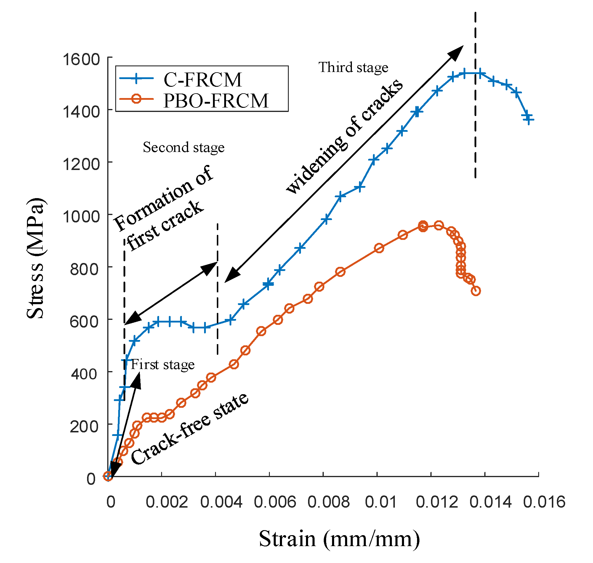
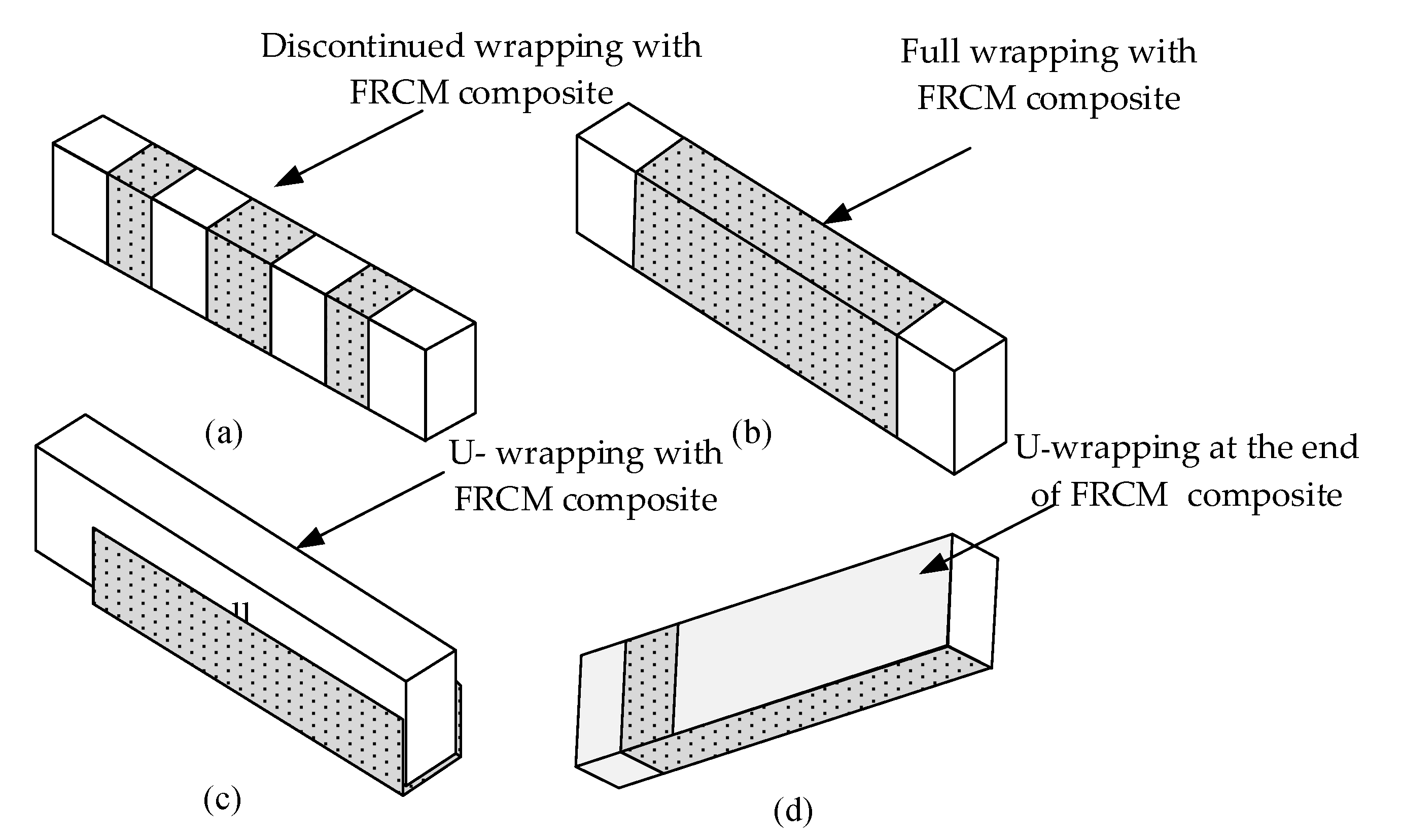


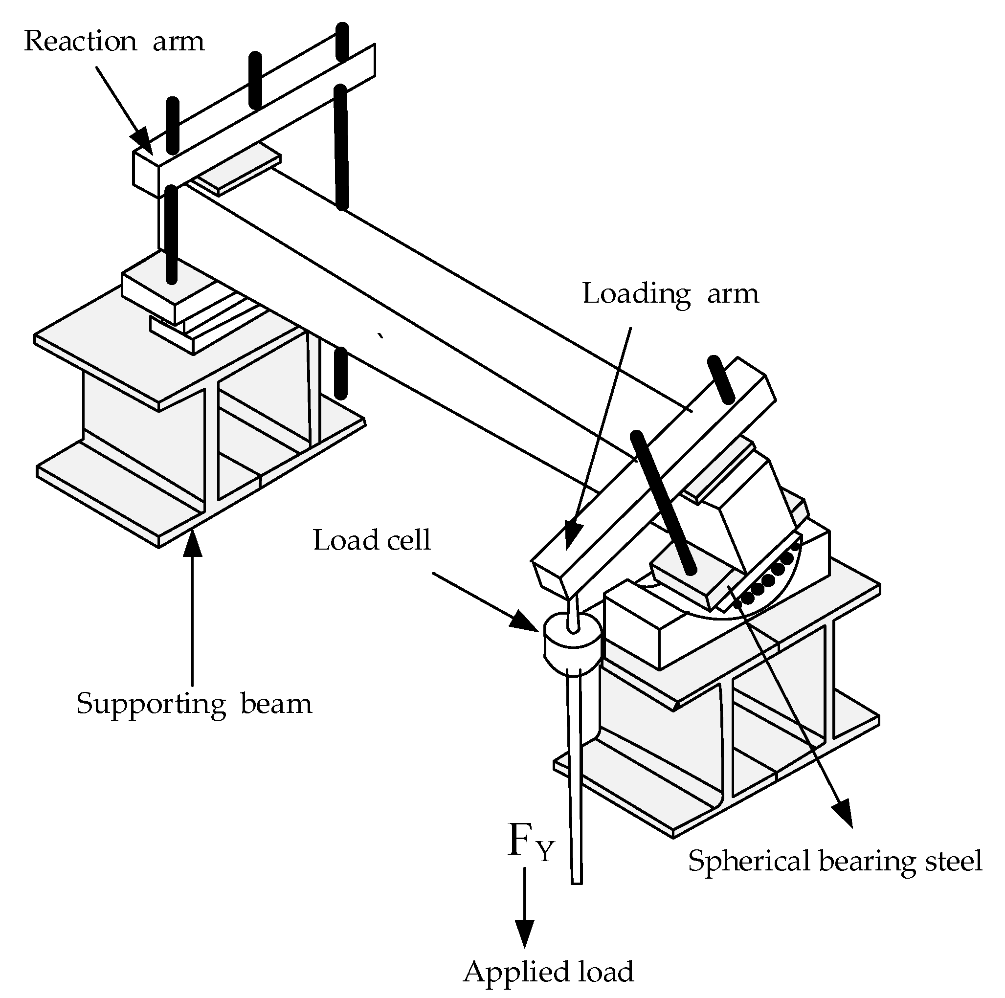
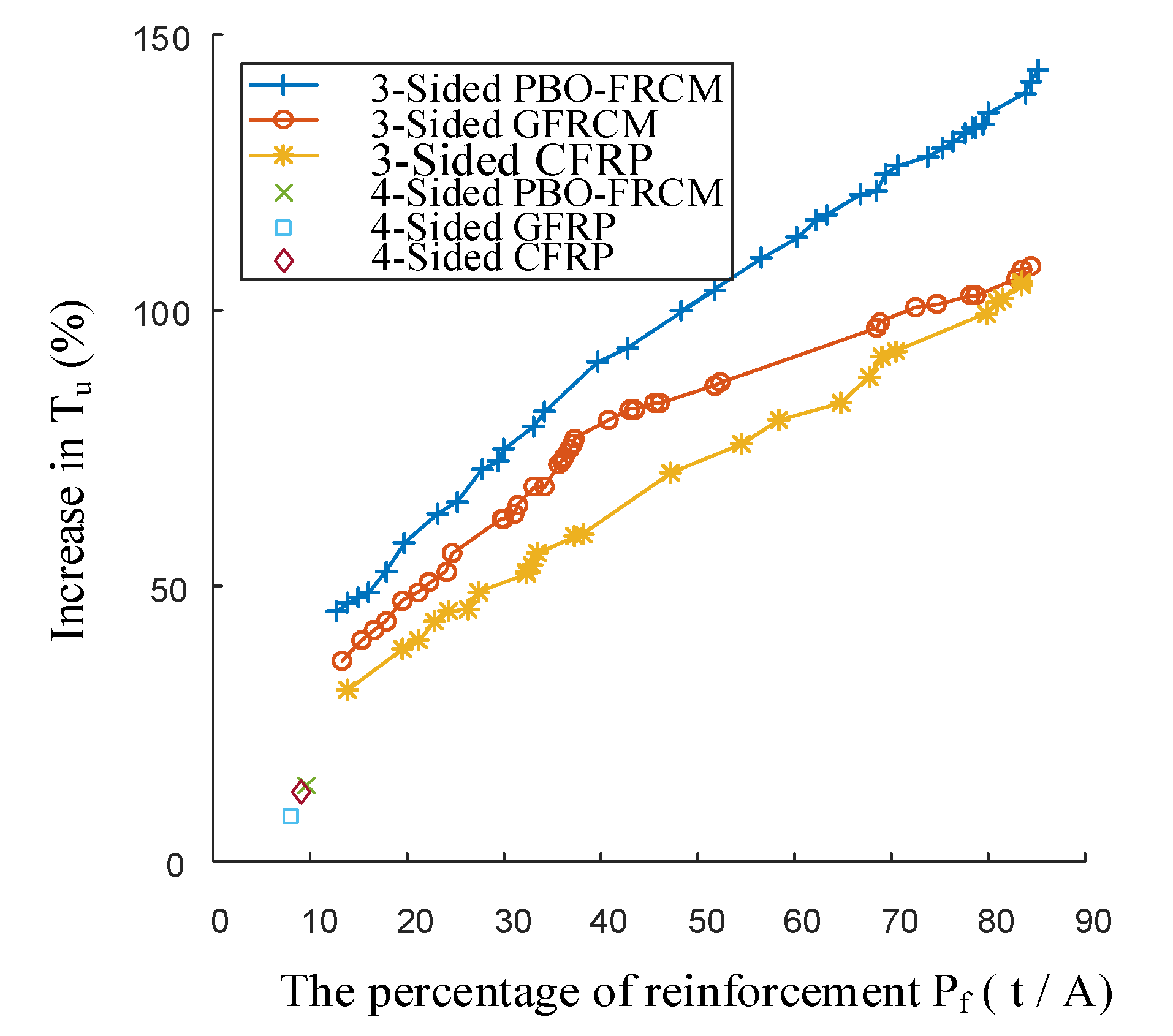
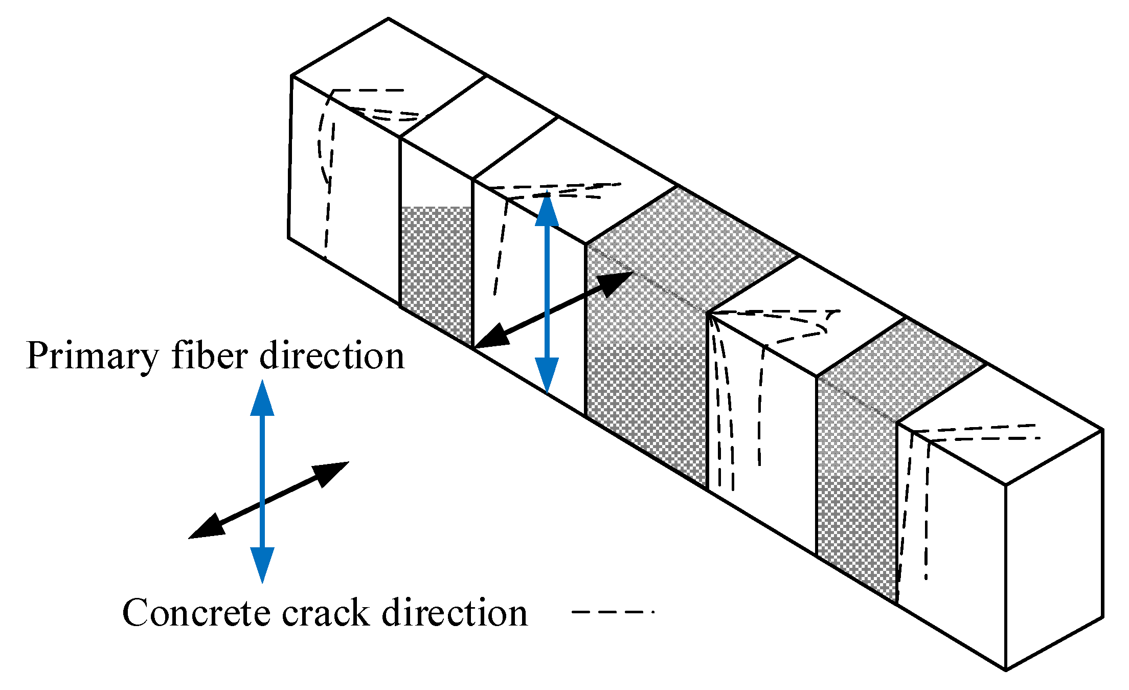
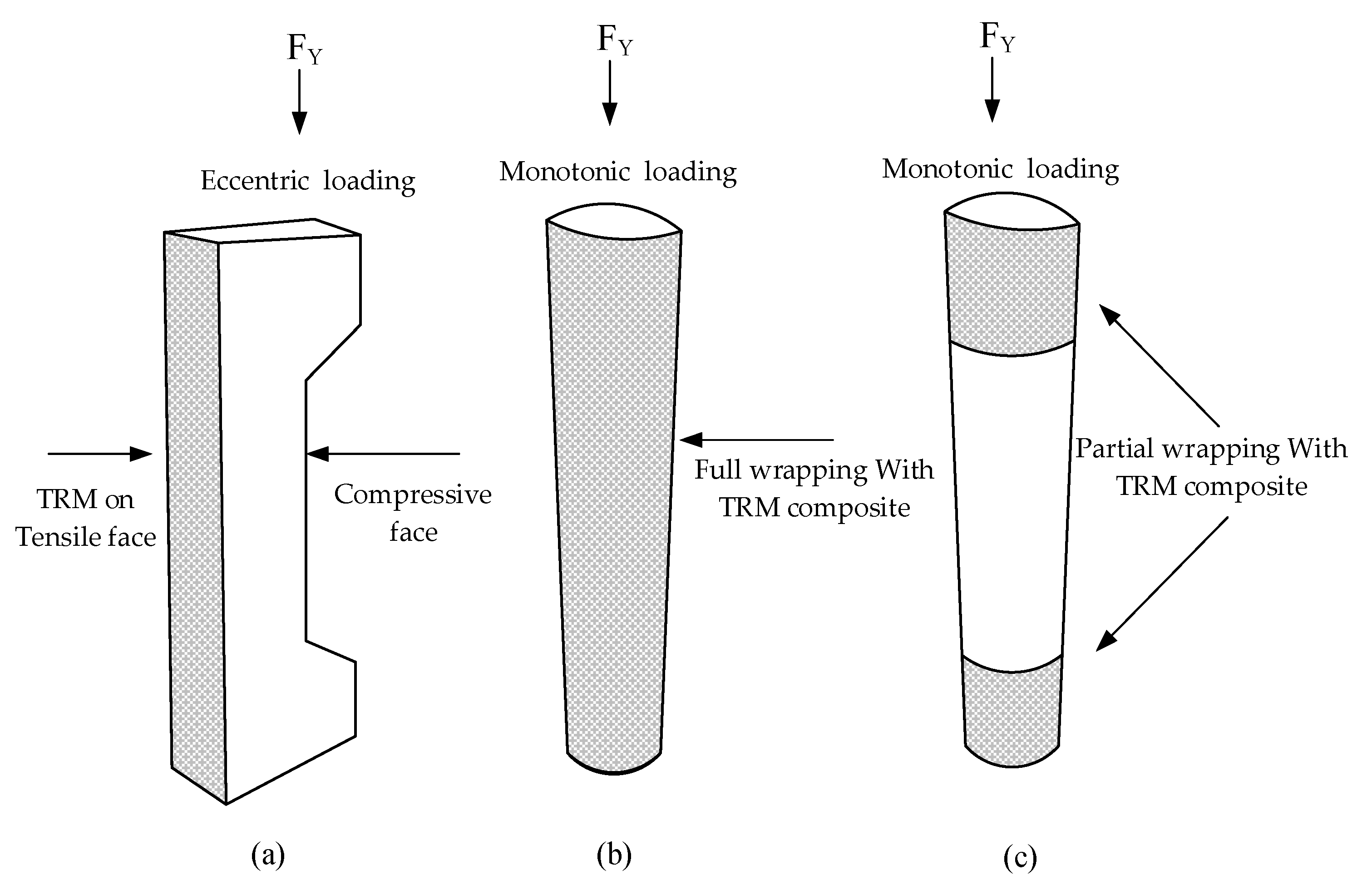
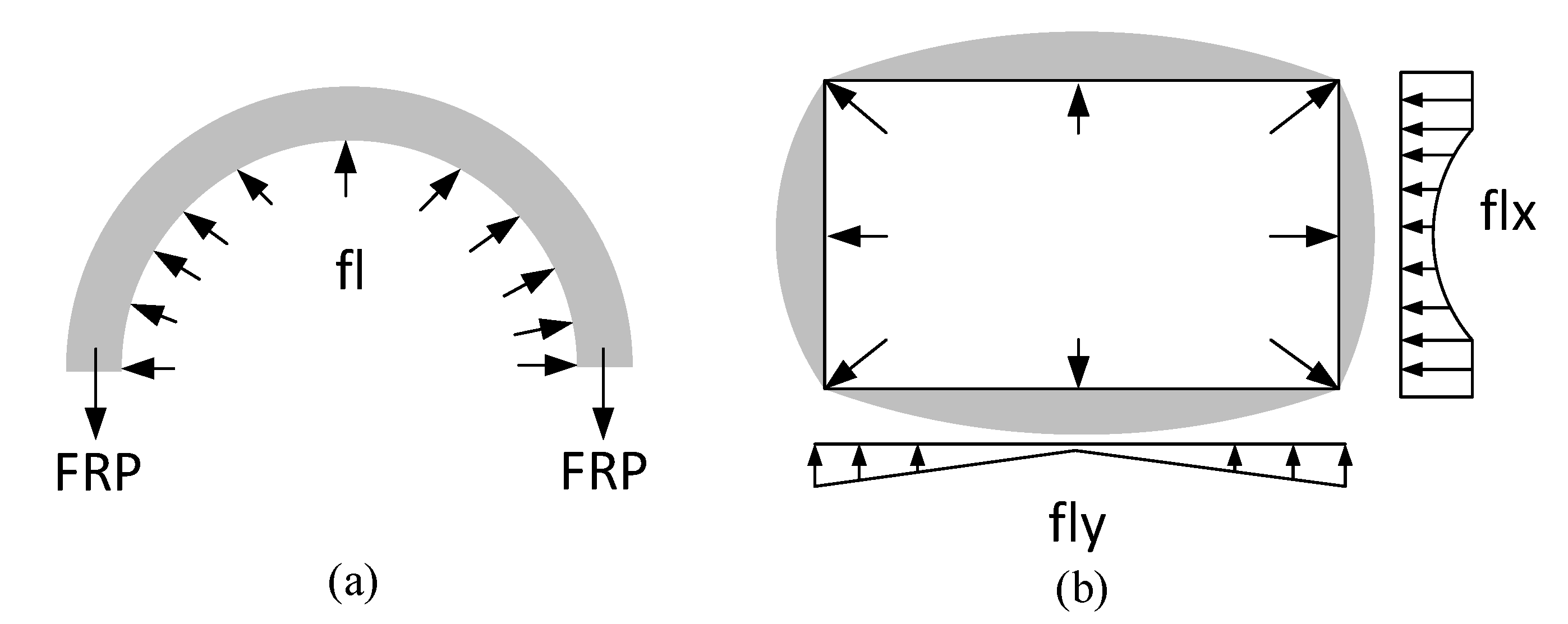


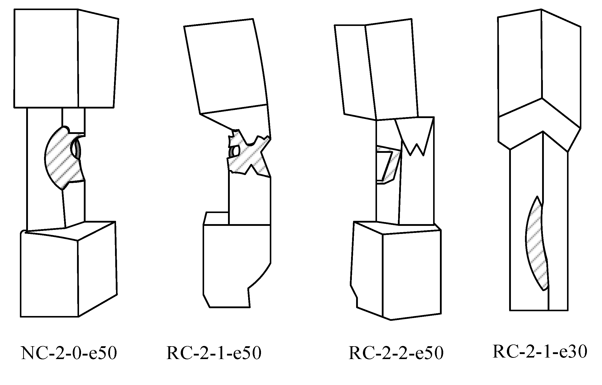
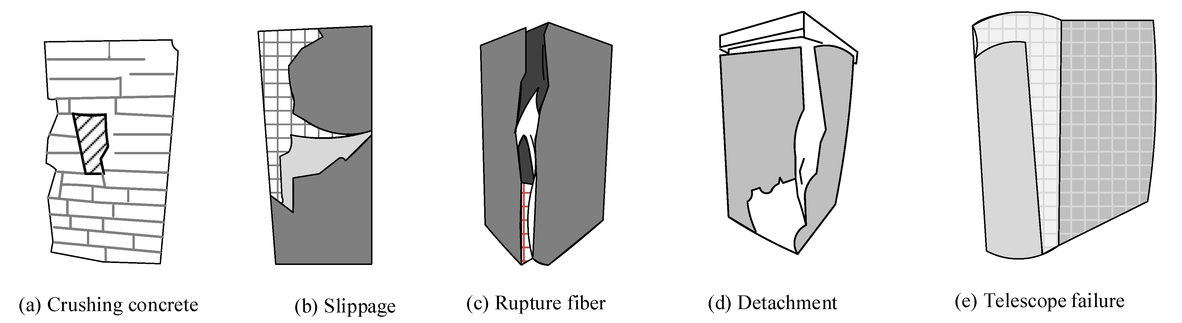


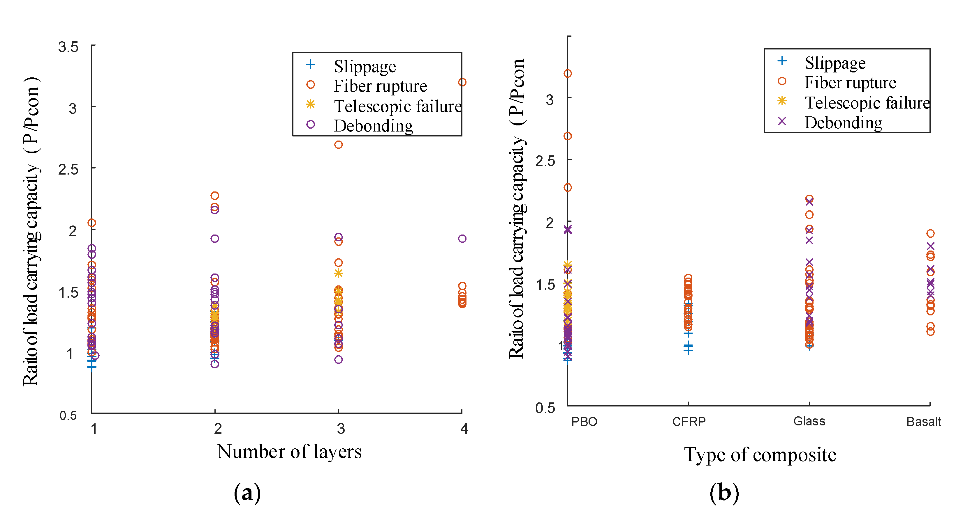
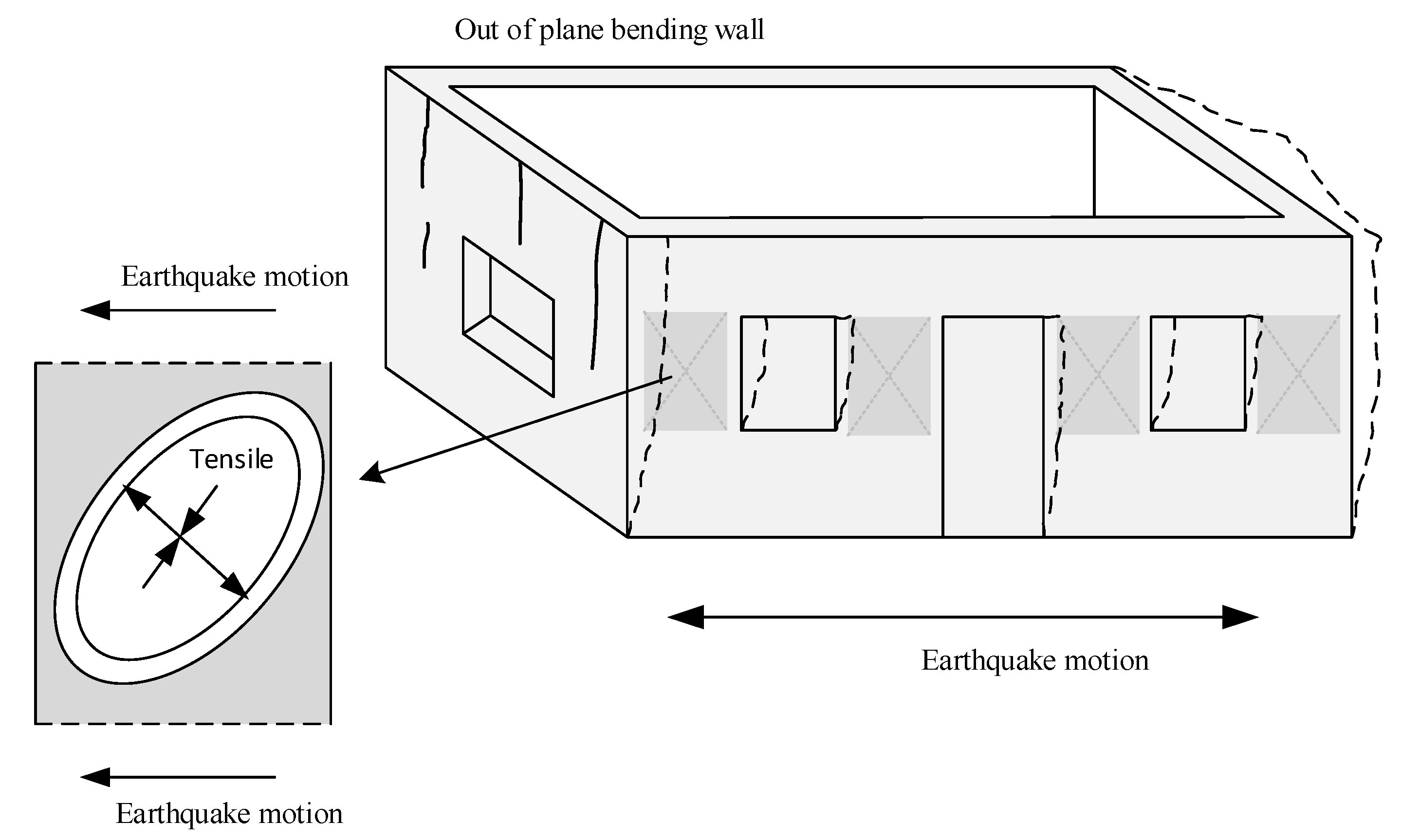
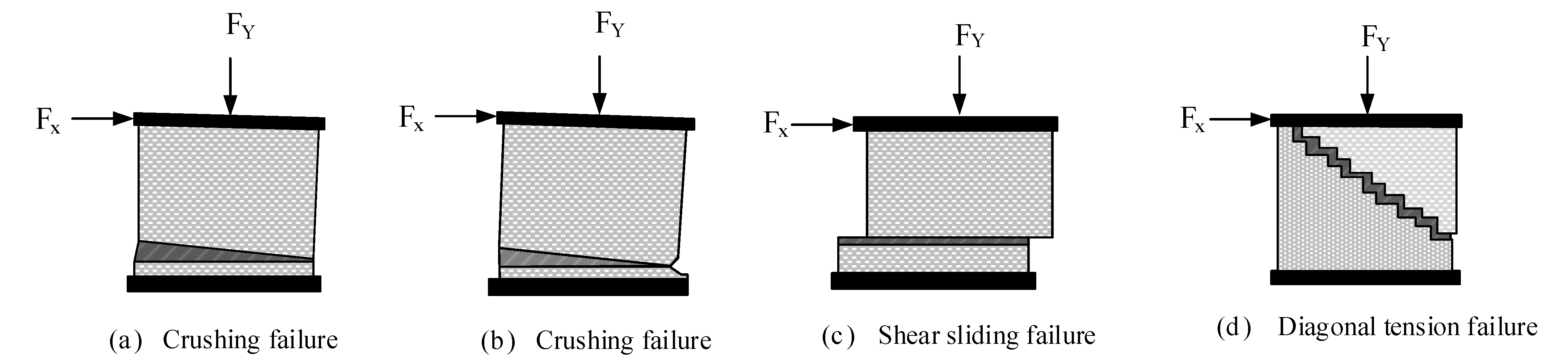
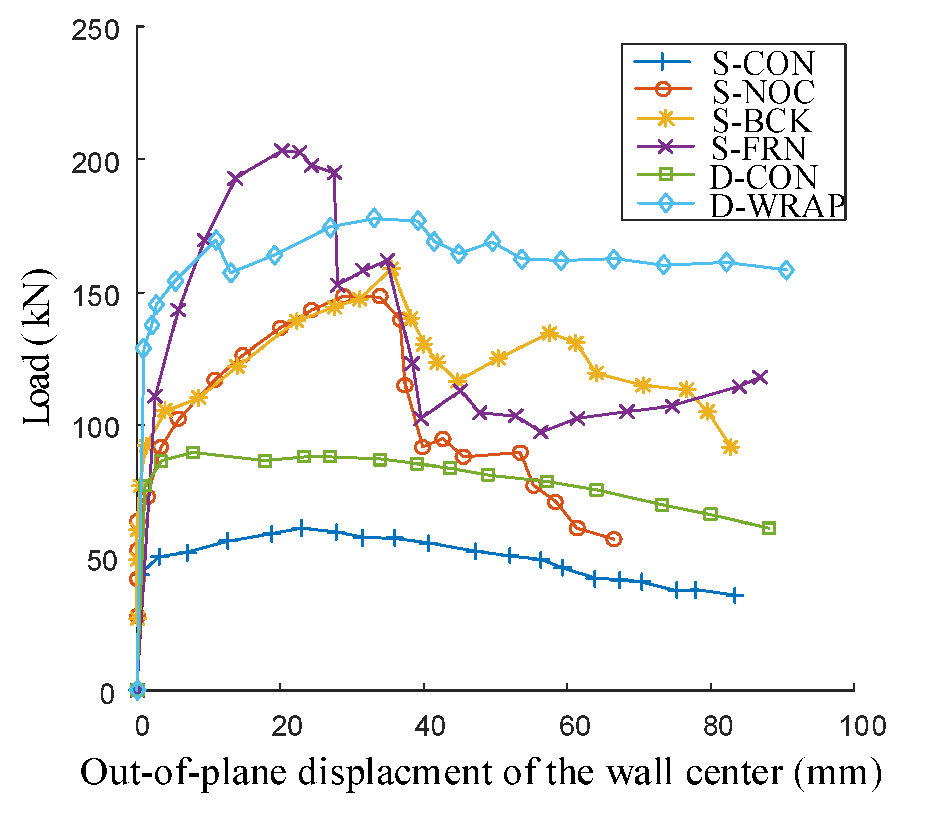
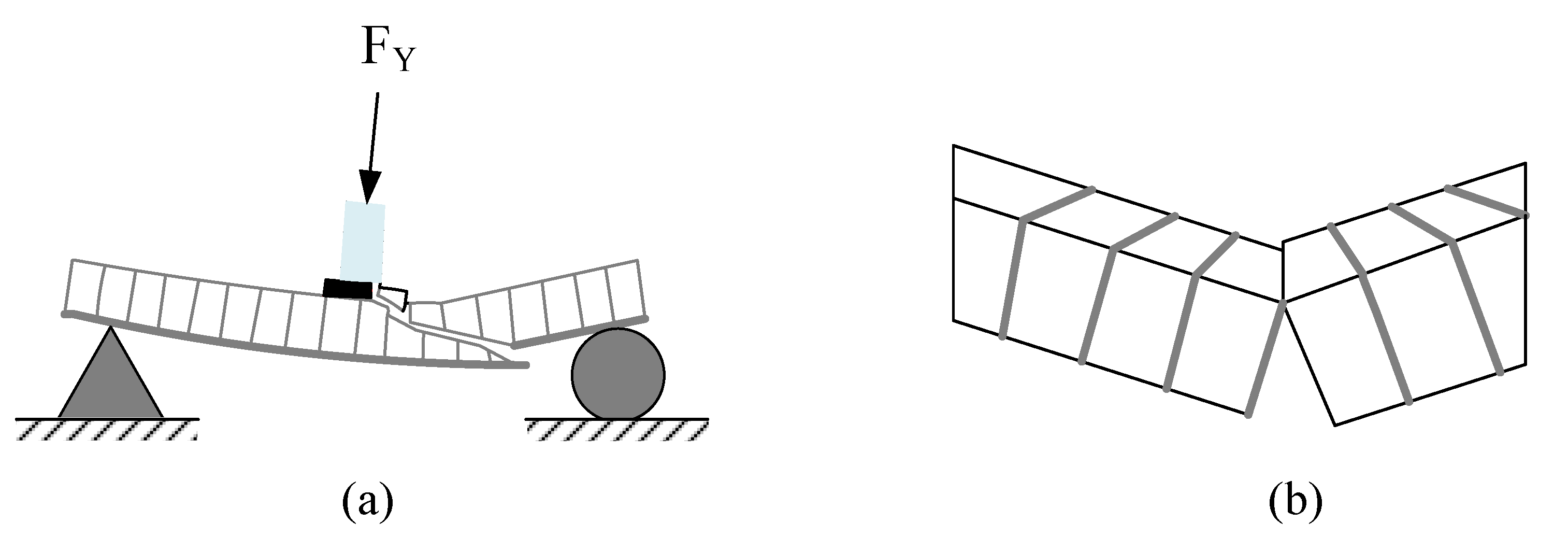
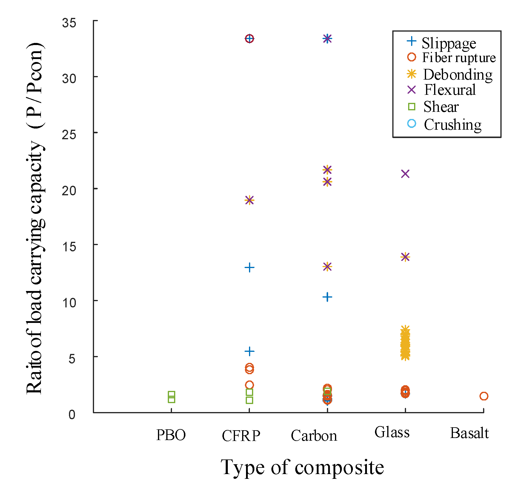
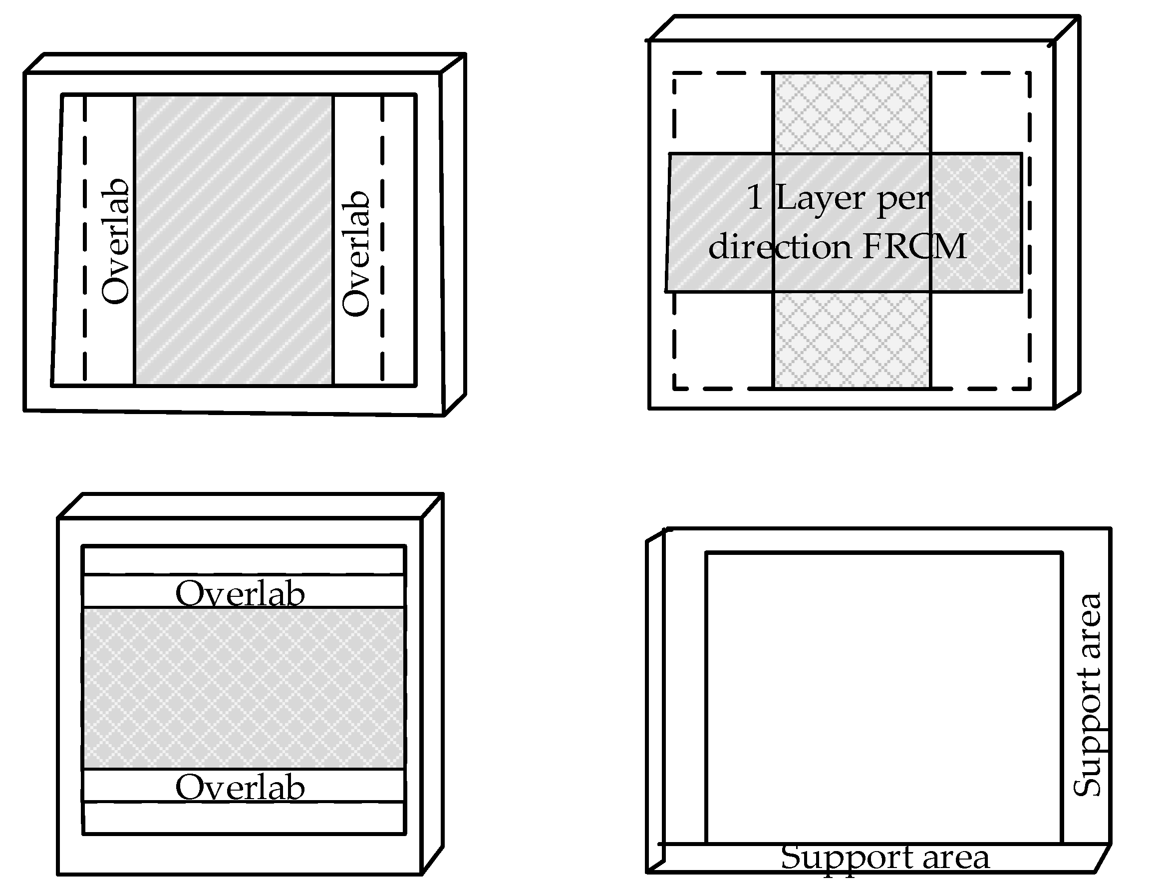


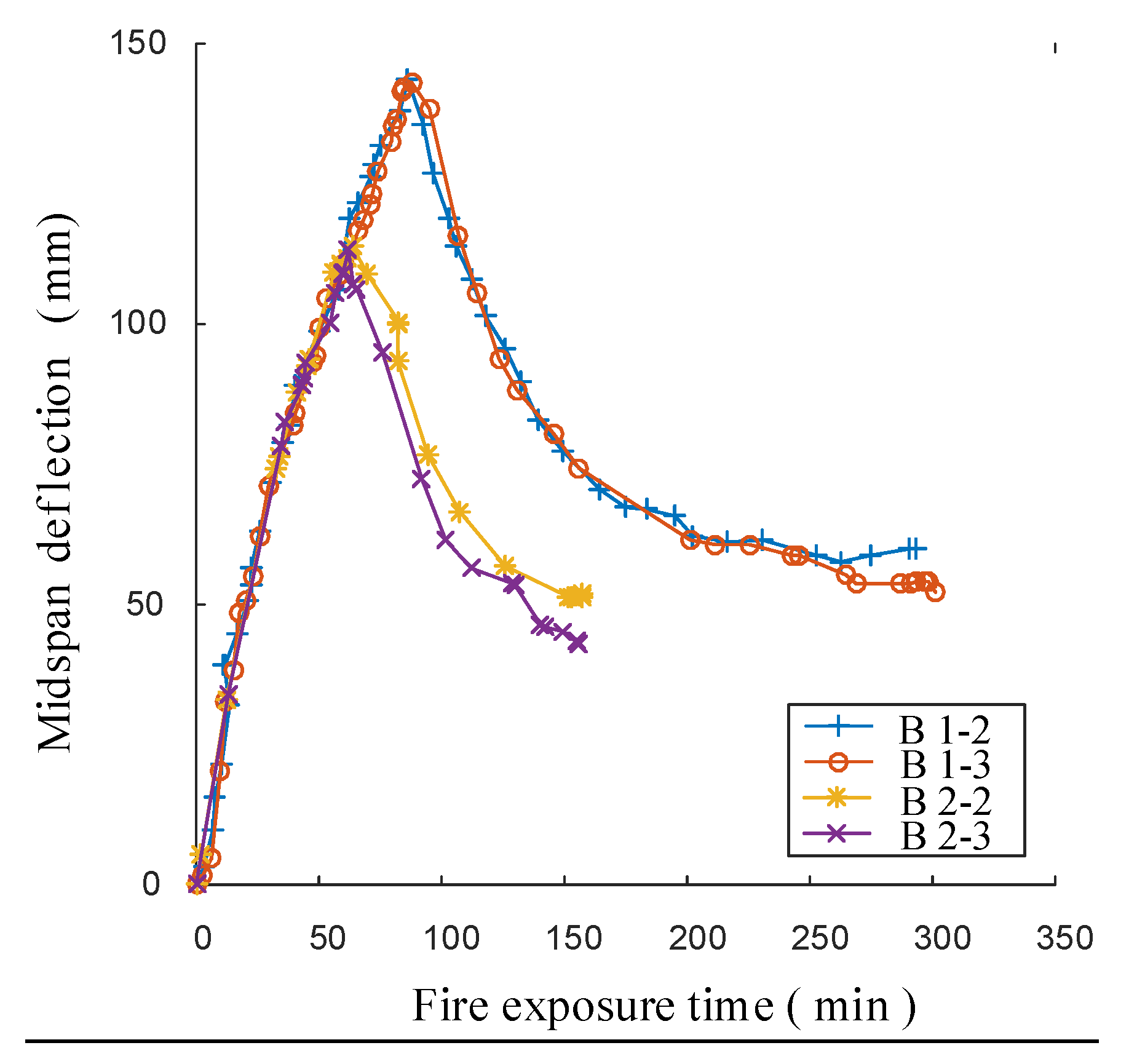

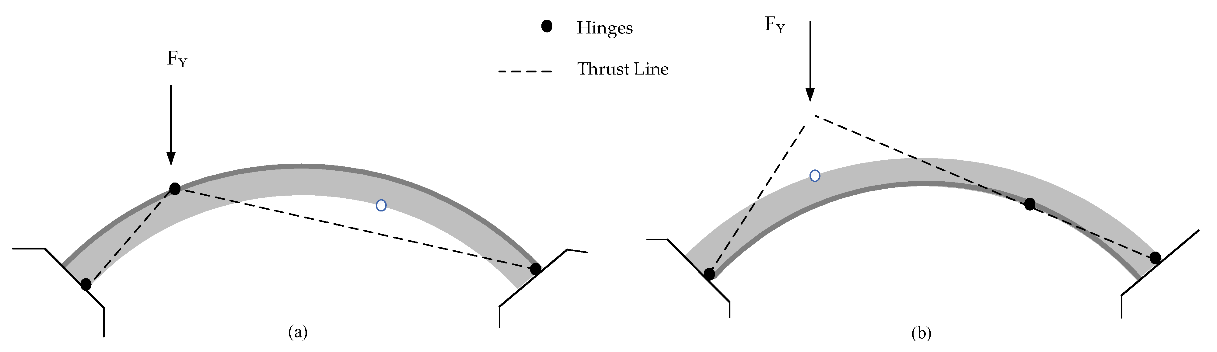
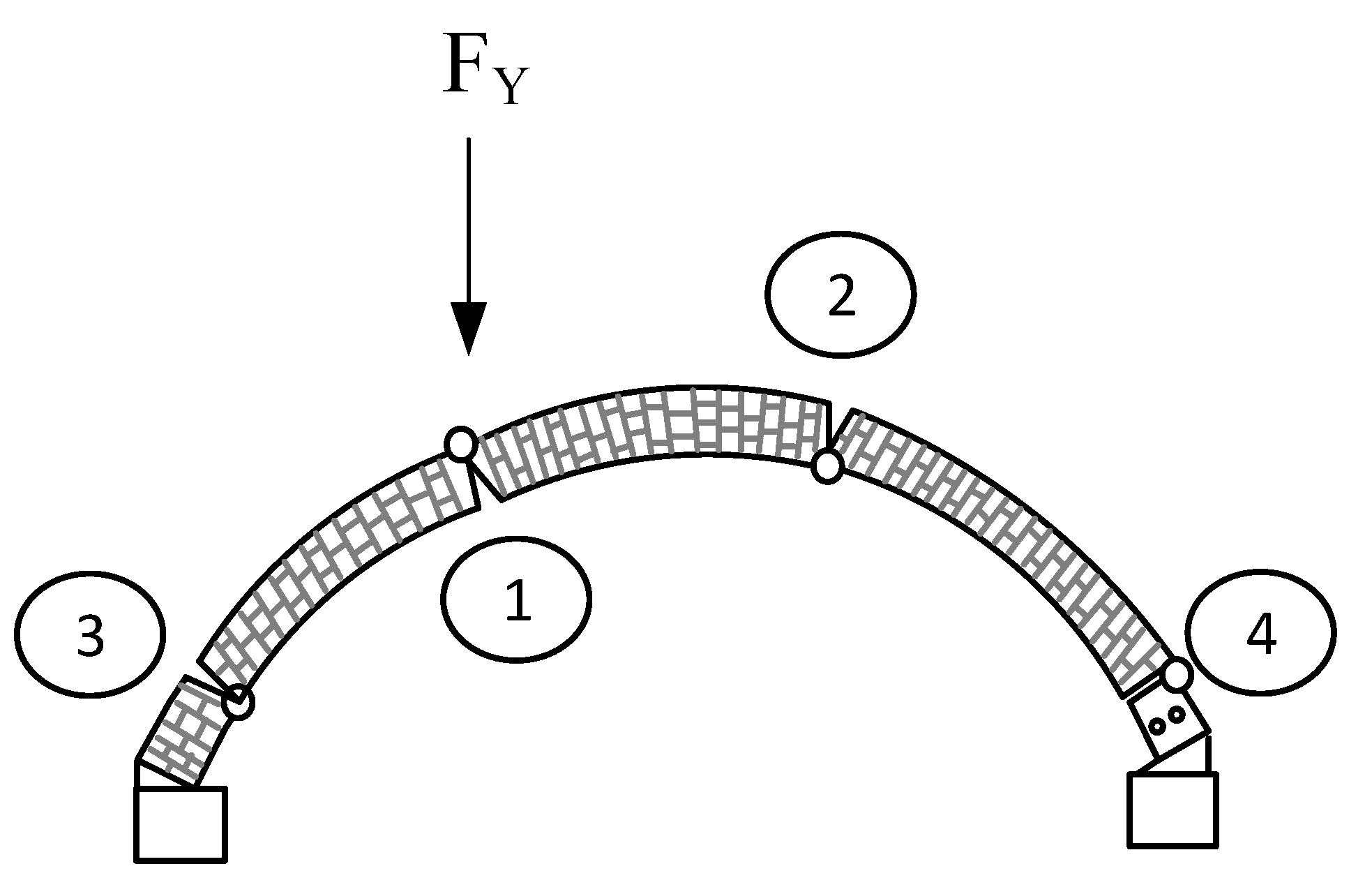
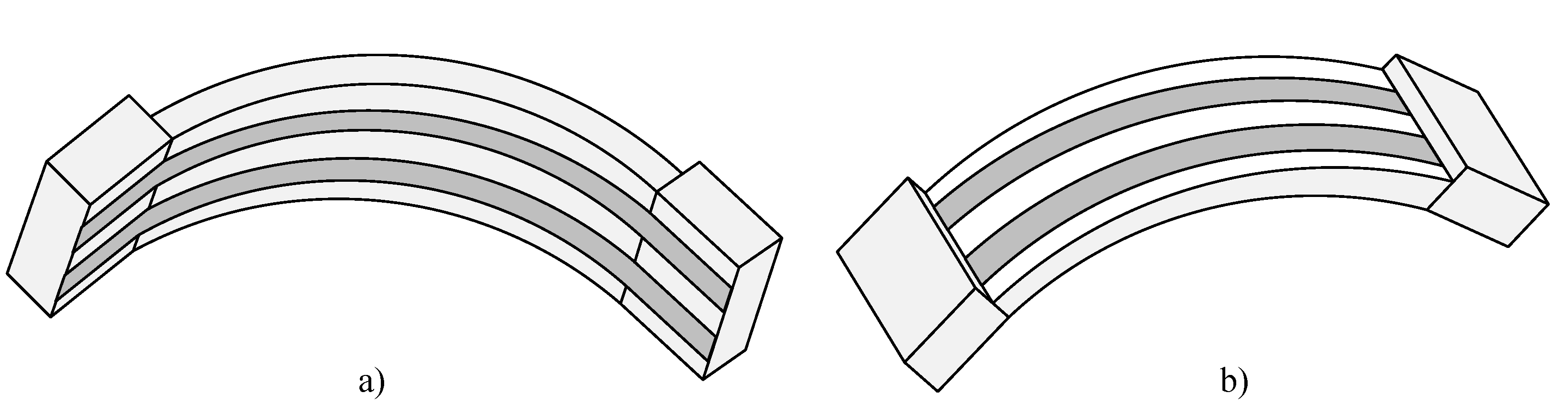
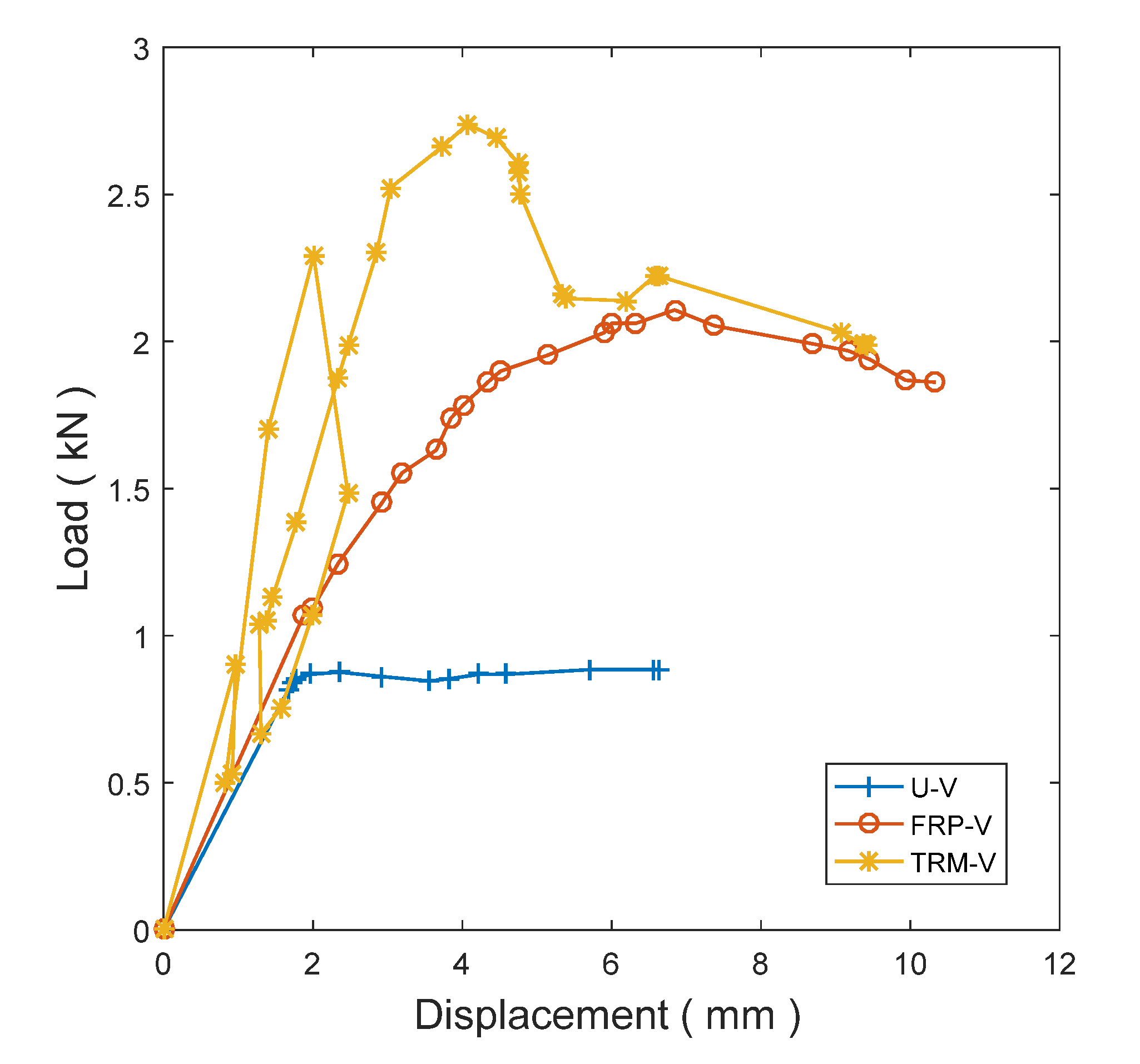


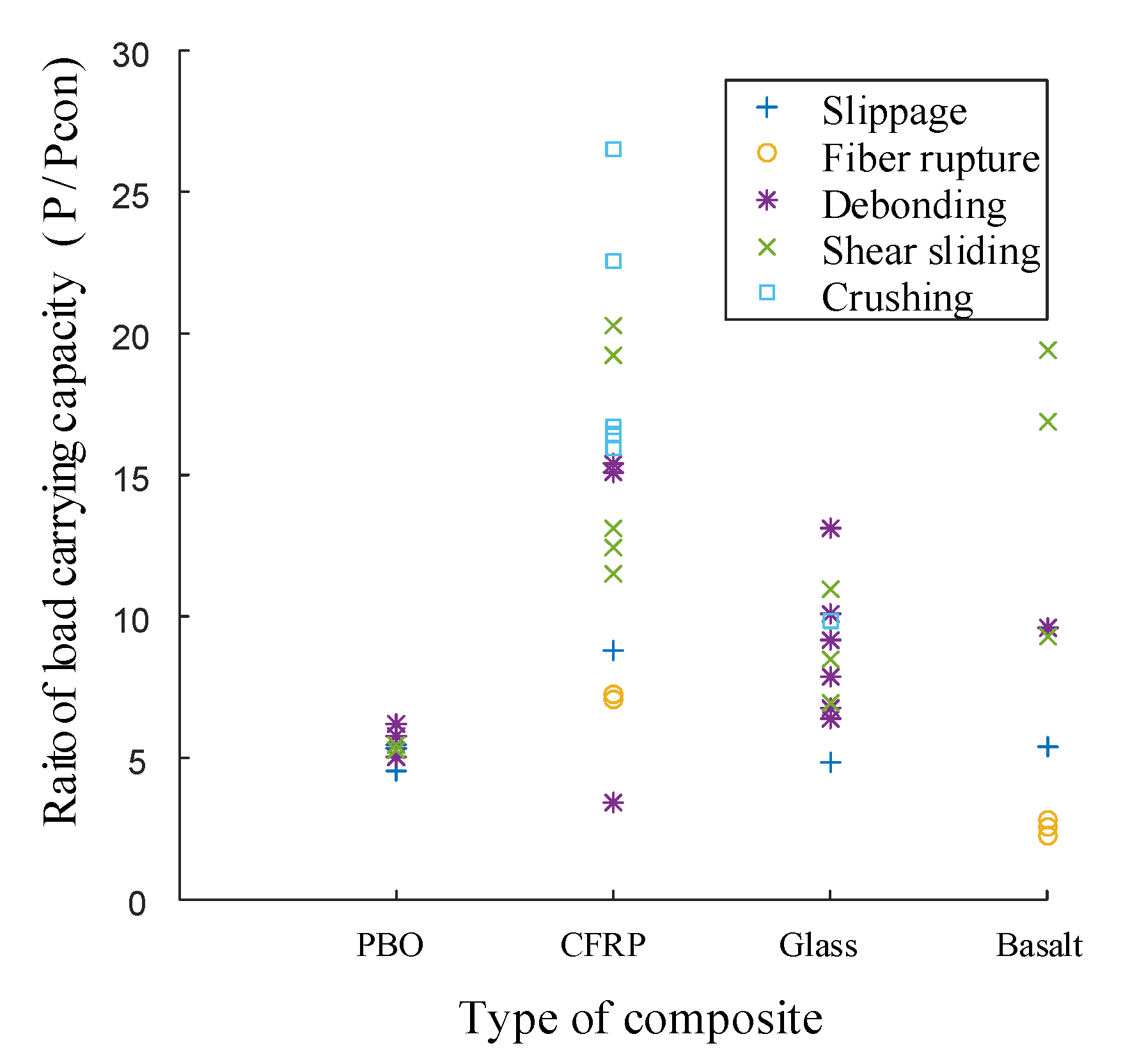

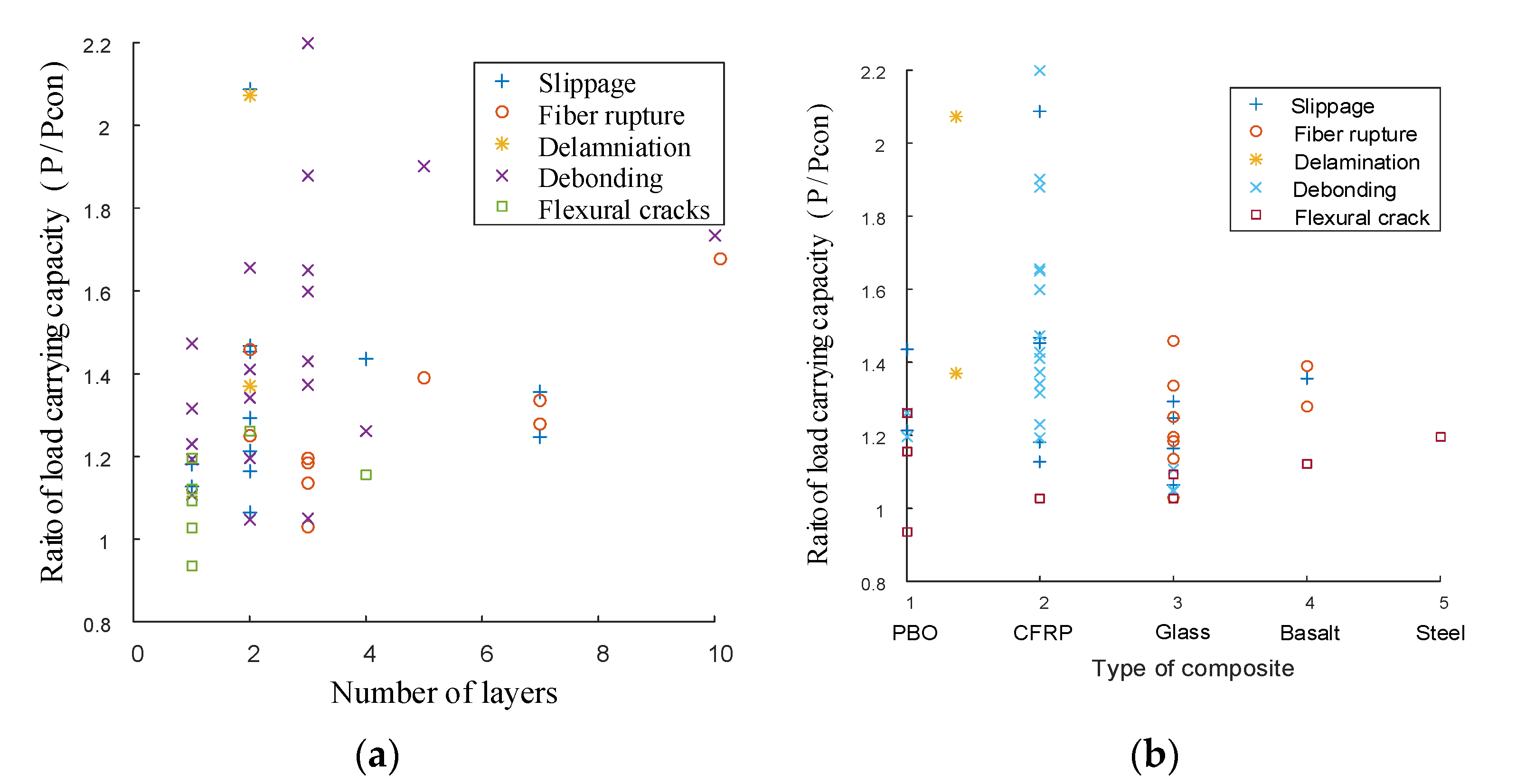
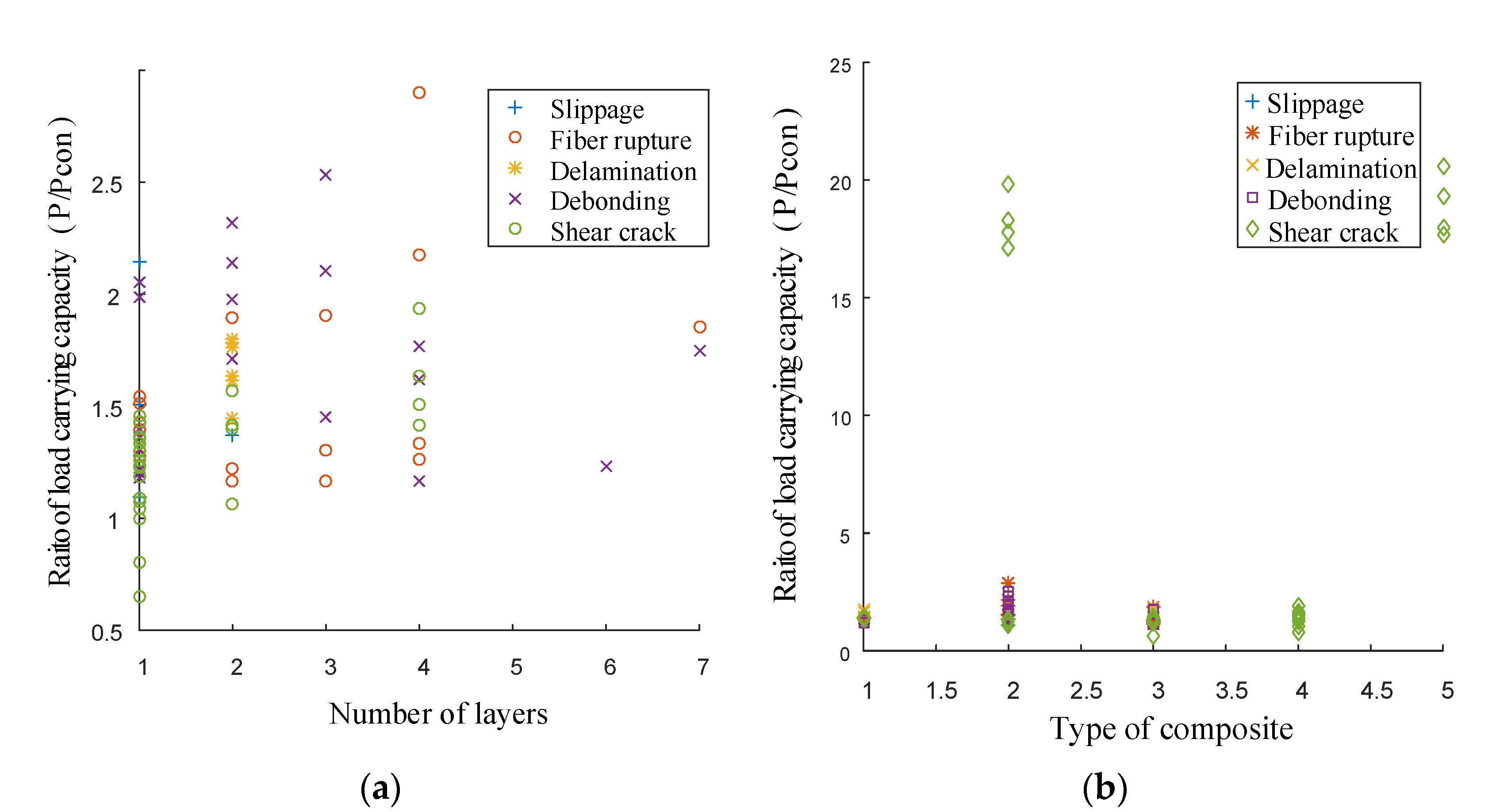
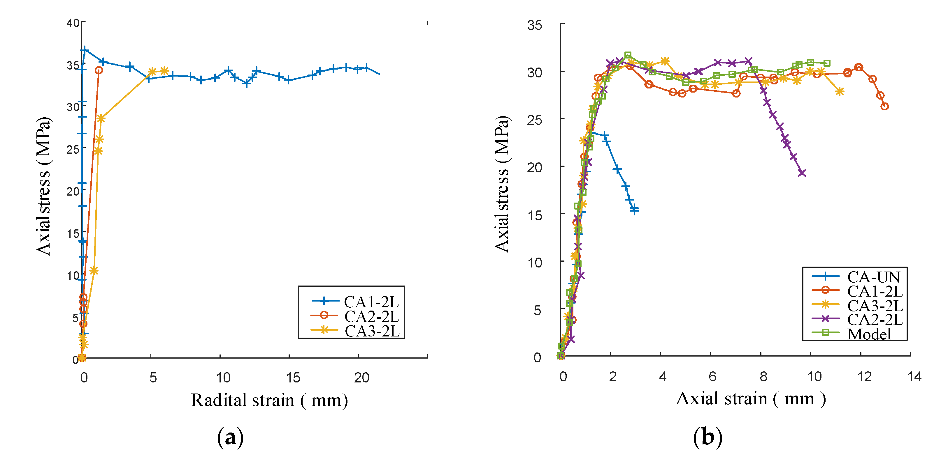
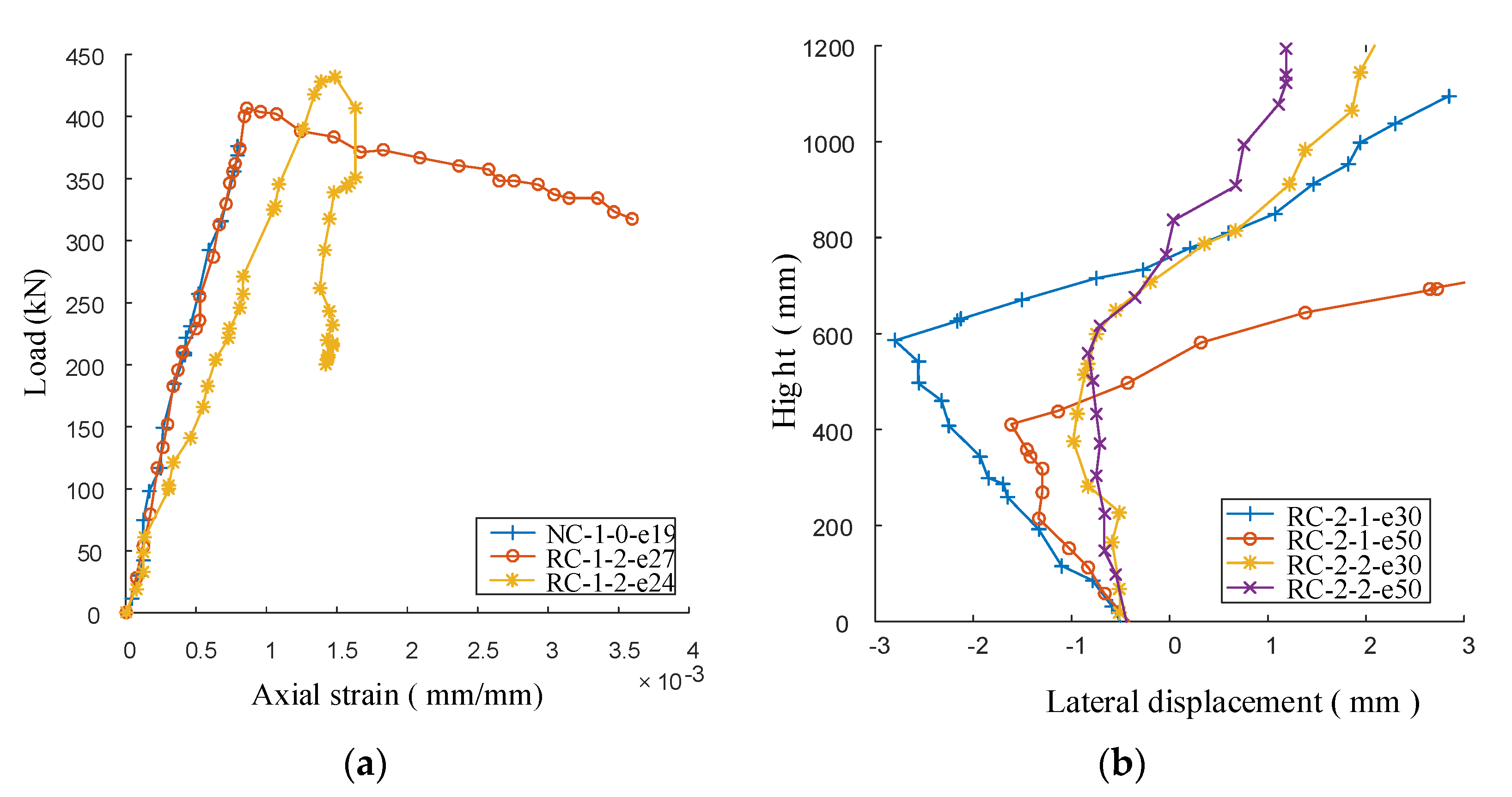
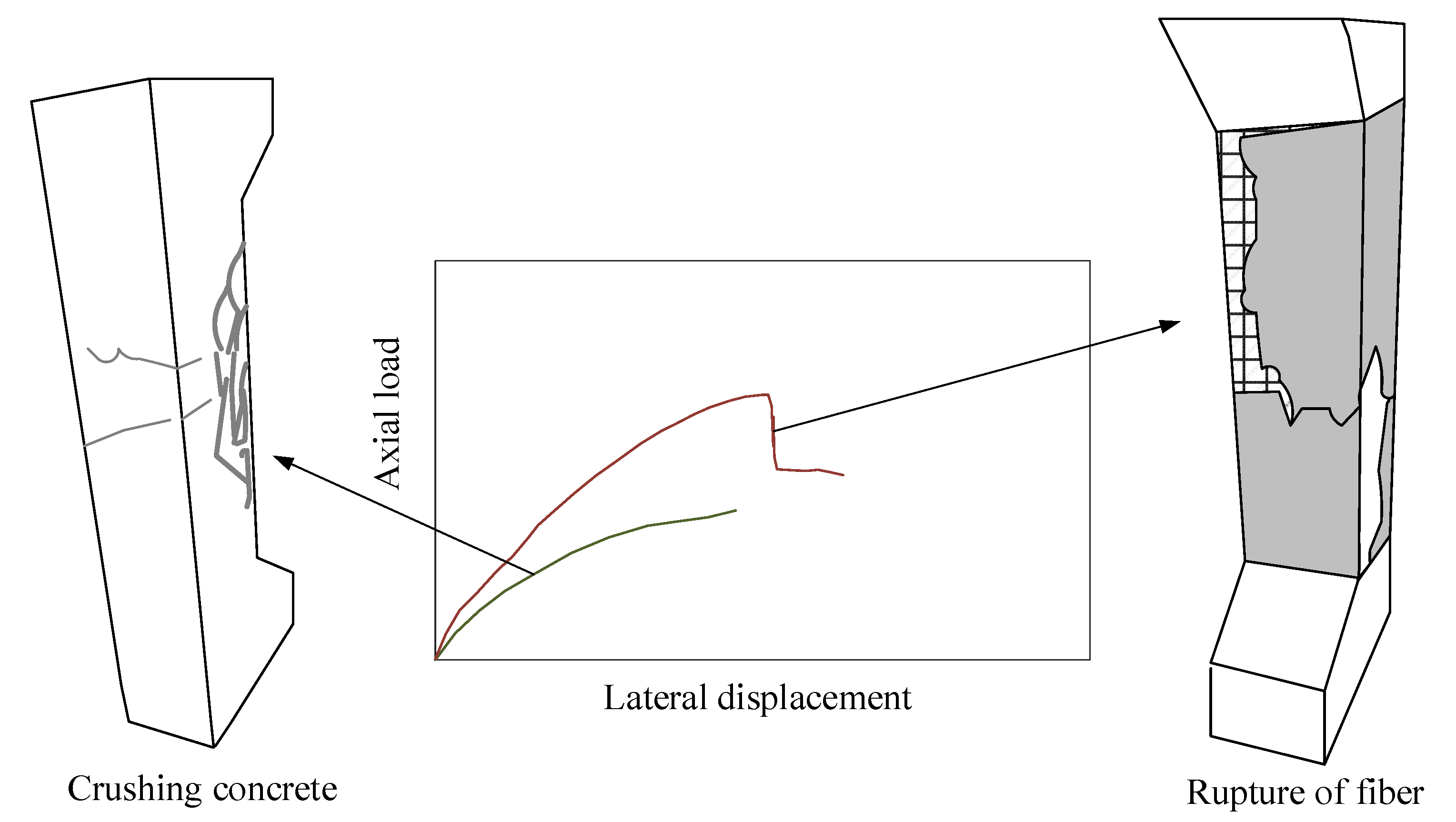
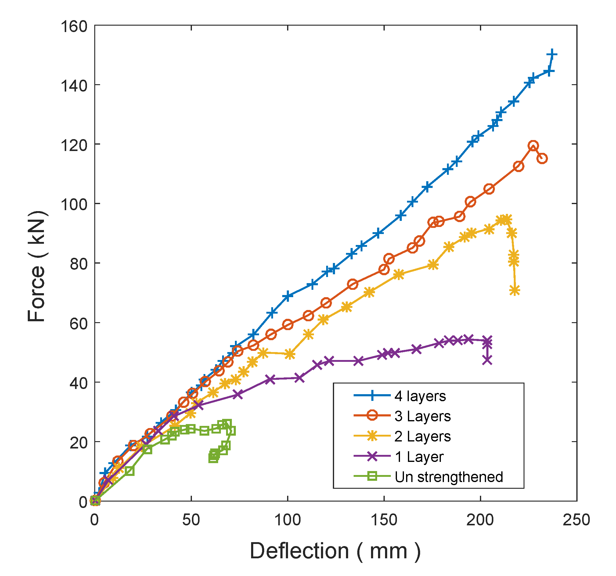
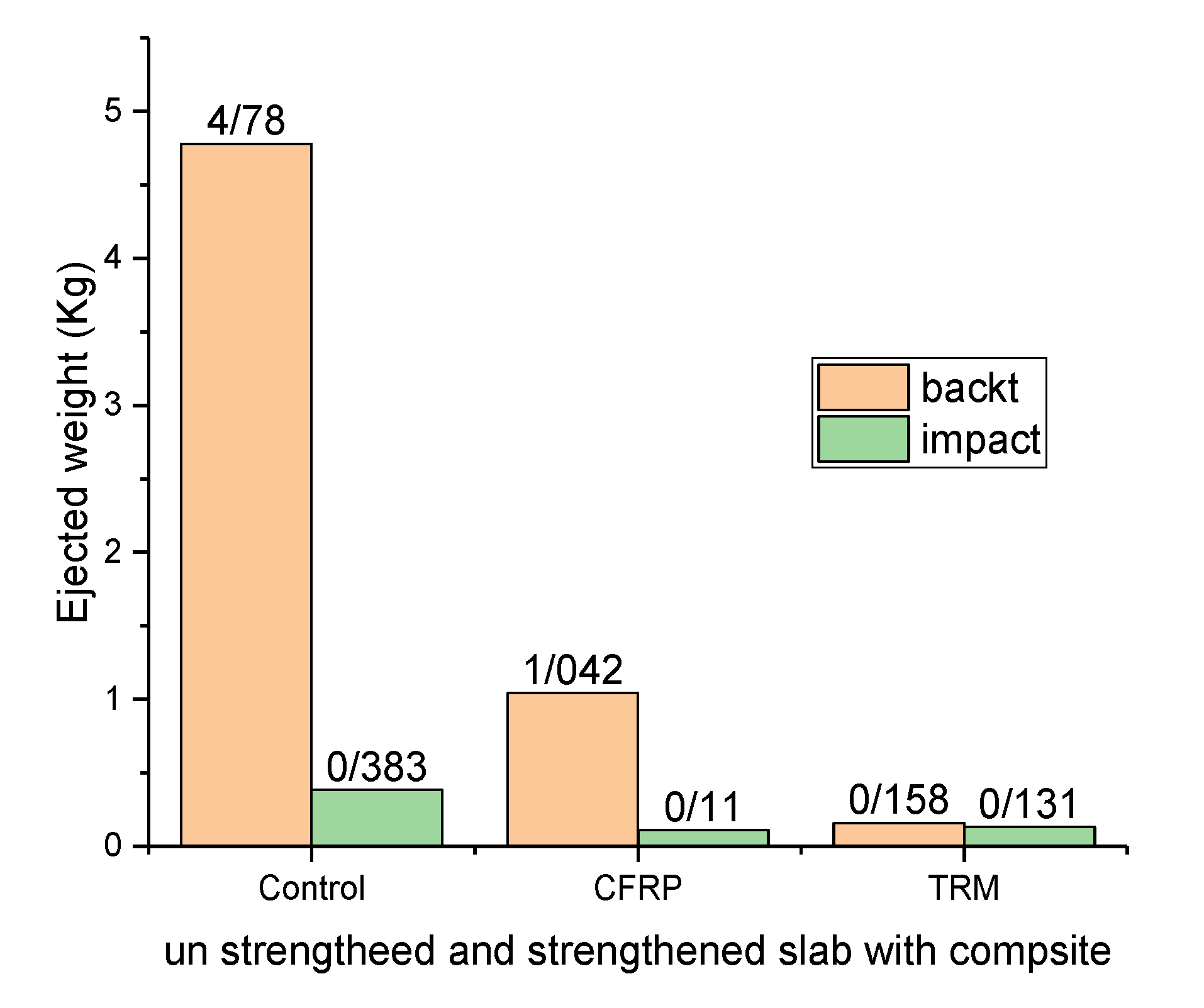
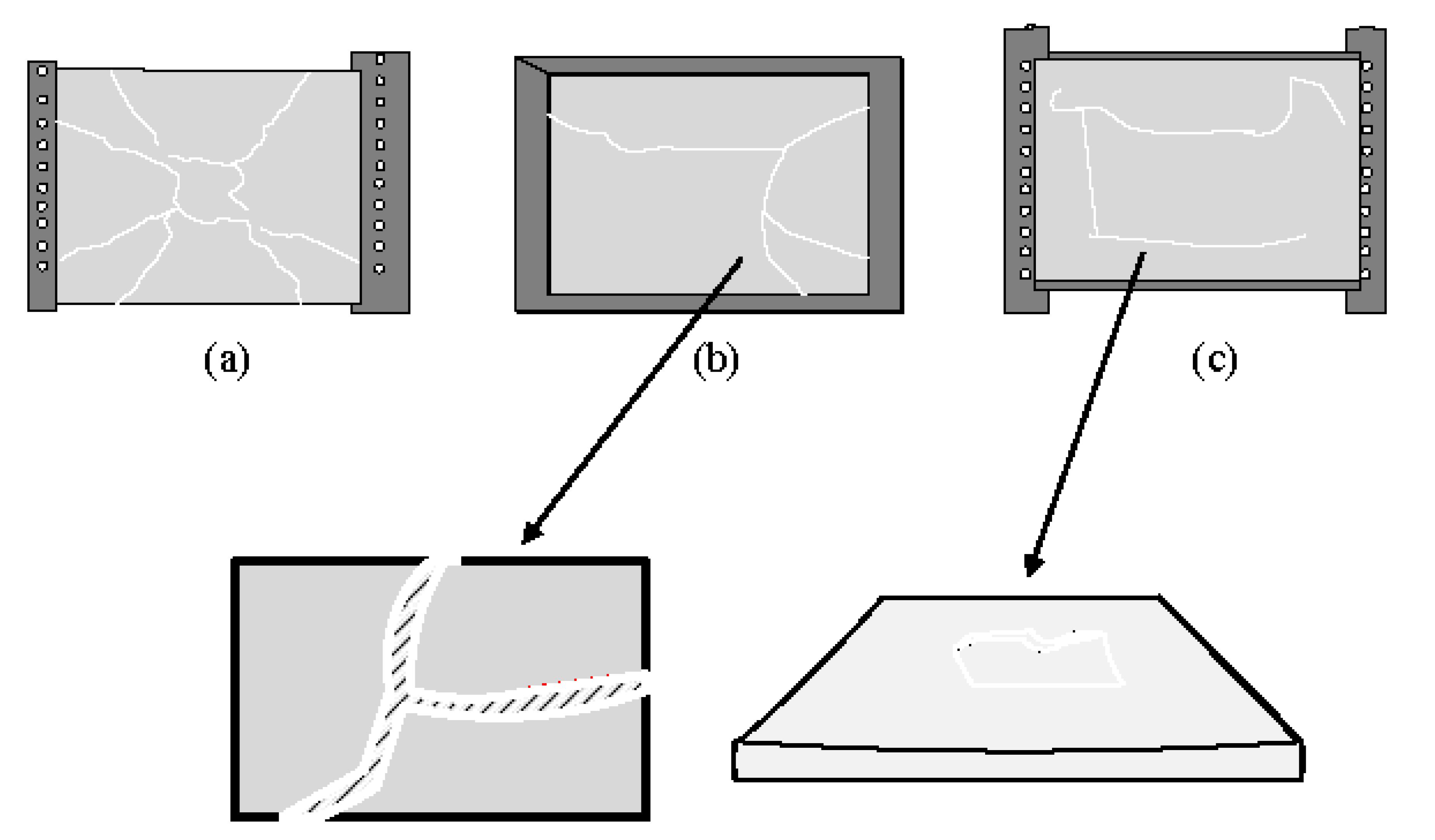
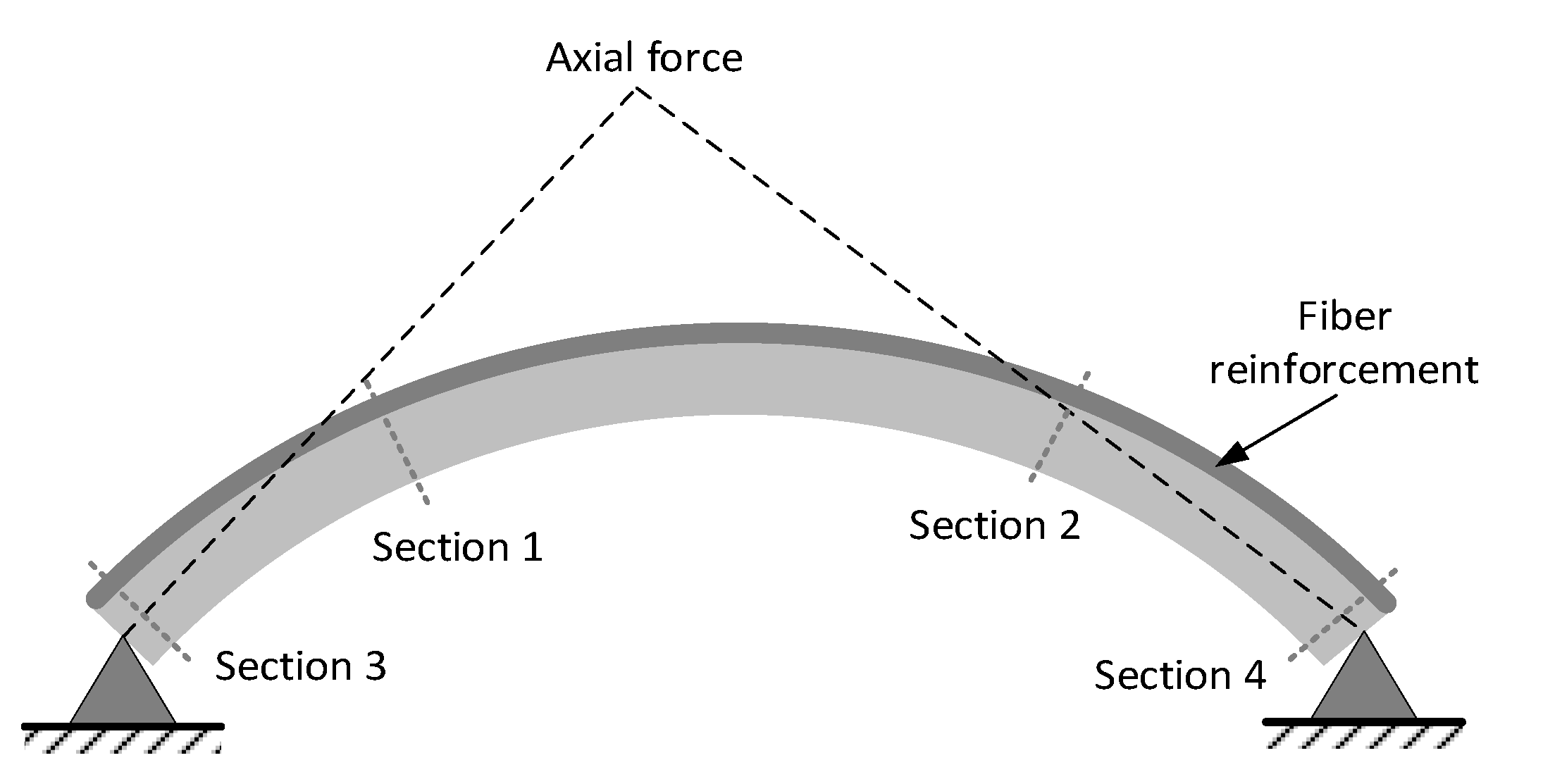
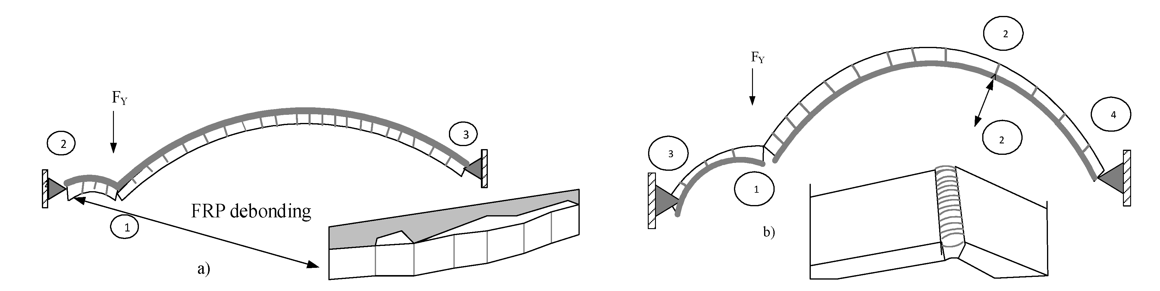