
Experimental Investigation of h-Type Supporting System for Excavation beneath Existing Underground Space


Abstract
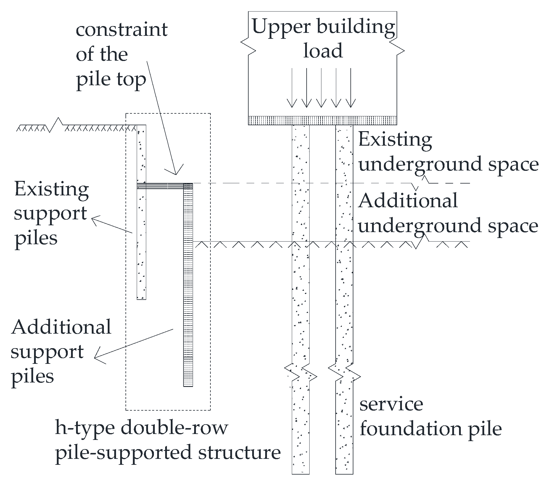
:1. Introduction
1.1. Previous Research
1.2. Research Priority of This Paper
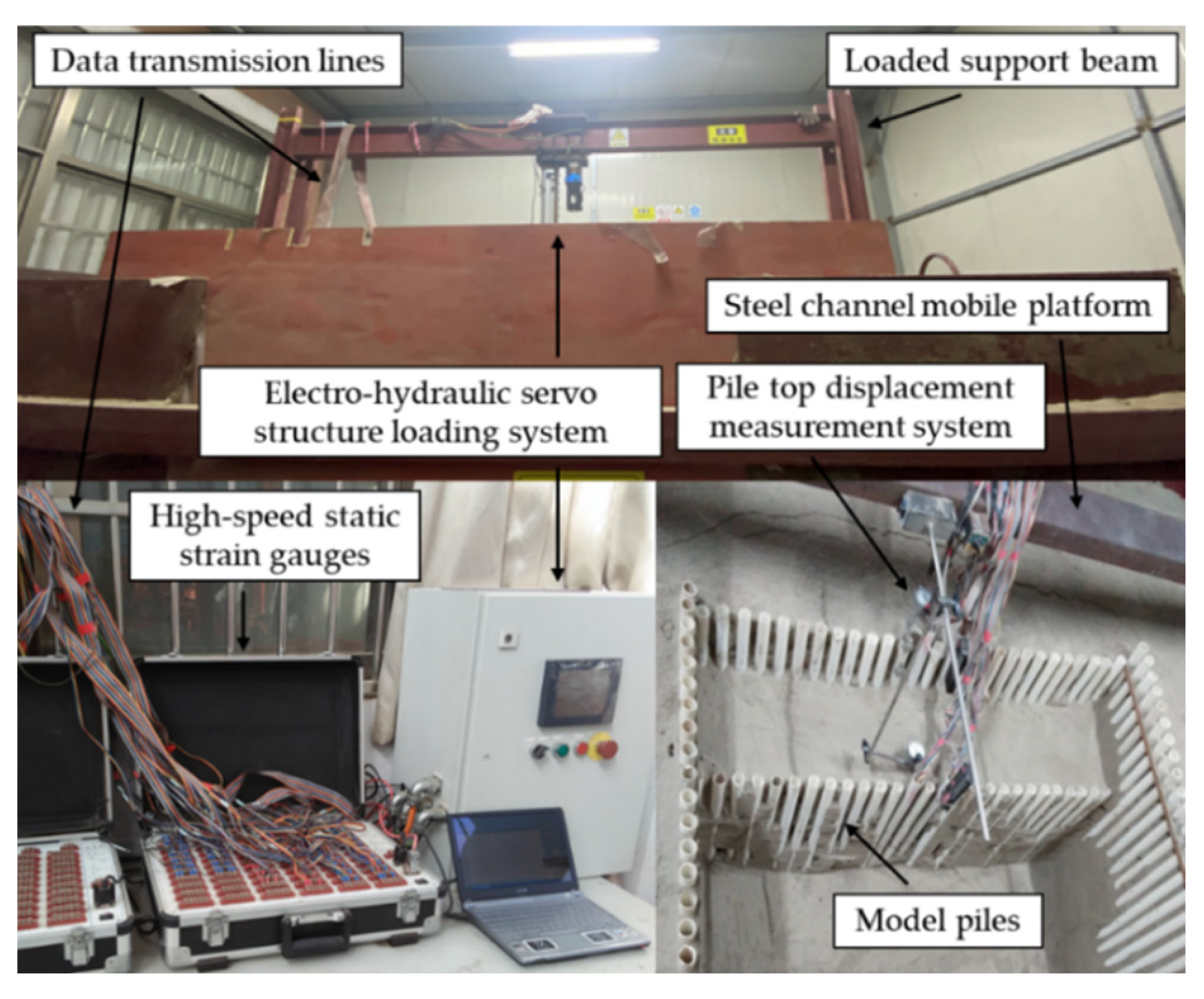
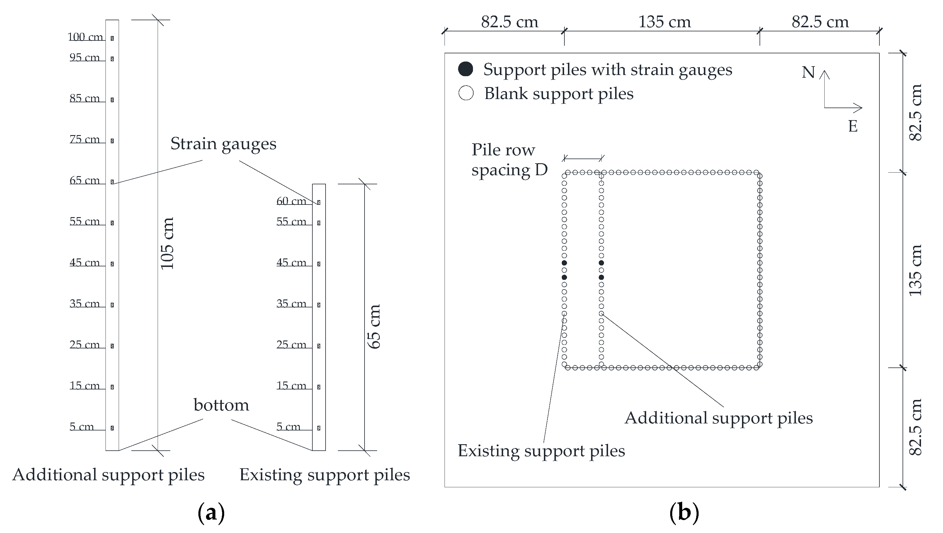
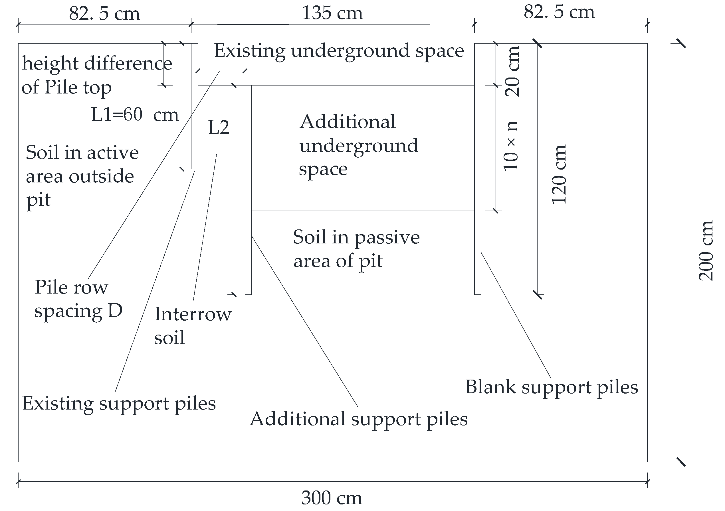
2. Test Arrangement
2.1. Test Preparation
2.2. Experimental Scheme
3. Observed Performance and Discussion
3.1. Influence and Effect of Pile Row Spacing
3.2. Influencing Effect of Pile Length Ratio
3.3. Influencing Effect of Pile-Head Constraint
3.4. Influencing Effect of Service Foundation Pile
3.5. Validity Research
3.6. Safety and Stability Analysis
3.7. Discussion
4. Conclusions
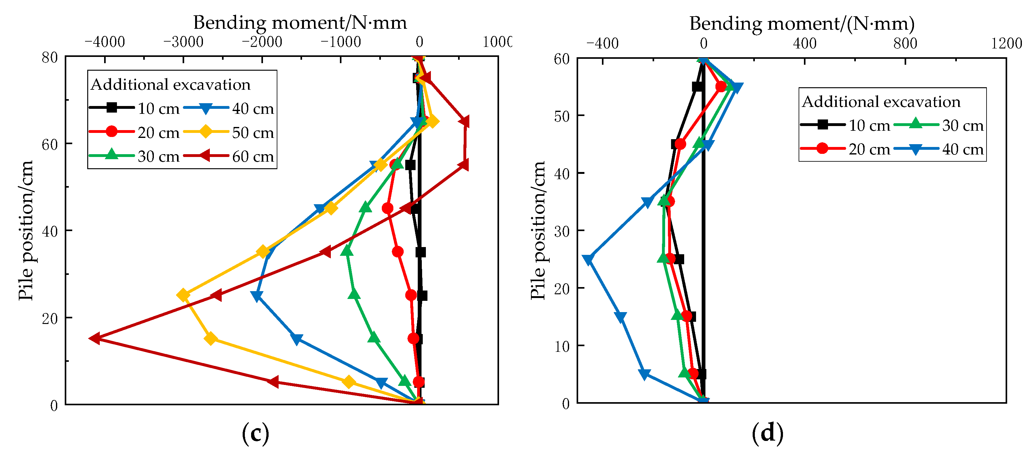
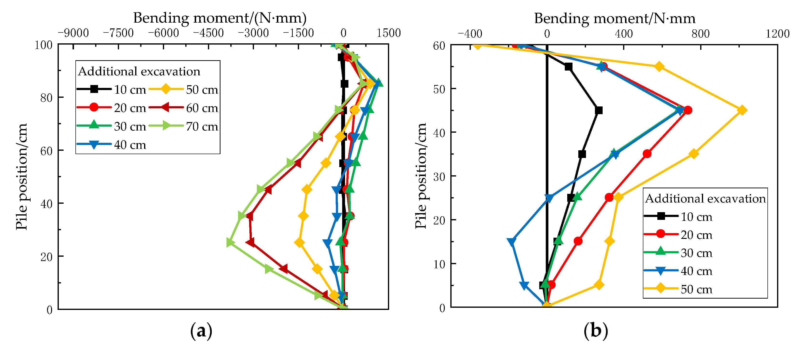
- Increasing pile spacing within a certain range can increase the positive bending moment of the upper part of the additional support piles and decrease the negative bending moment of the lower part, such that the bending moment distribution of the pile is more reasonable, and the stress state of the pile is optimized. When the spacing between piles is large, the increase in soil thickness between piles enhances the back pressure on the existing support piles, such that the force of the existing support piles is stable. In addition, the front piles play an important bearing role in the double-row pile support system, which is more helpful after failure of the back piles;
- The additional excavation of the 40 cm layer is a critical point in the test. It can be preliminarily concluded that the existing support pile is in a state of dumping destruction after the additional excavation depth reaches the bottom of the existing support pile (40 cm). In addition, the pile top displacement is proportional to the excavation depth, and the growth rate of the pile top displacement increases with increasing excavation. Meanwhile, the interaction effect of the h-type double-row pile support system can significantly improve the overall stability of the retaining structure, which can promote the deformation and displacement control of the additional and existing support piles. Moreover, it is verified that row spacing of 10d appears to be the turning point beyond which the soil state is altered;
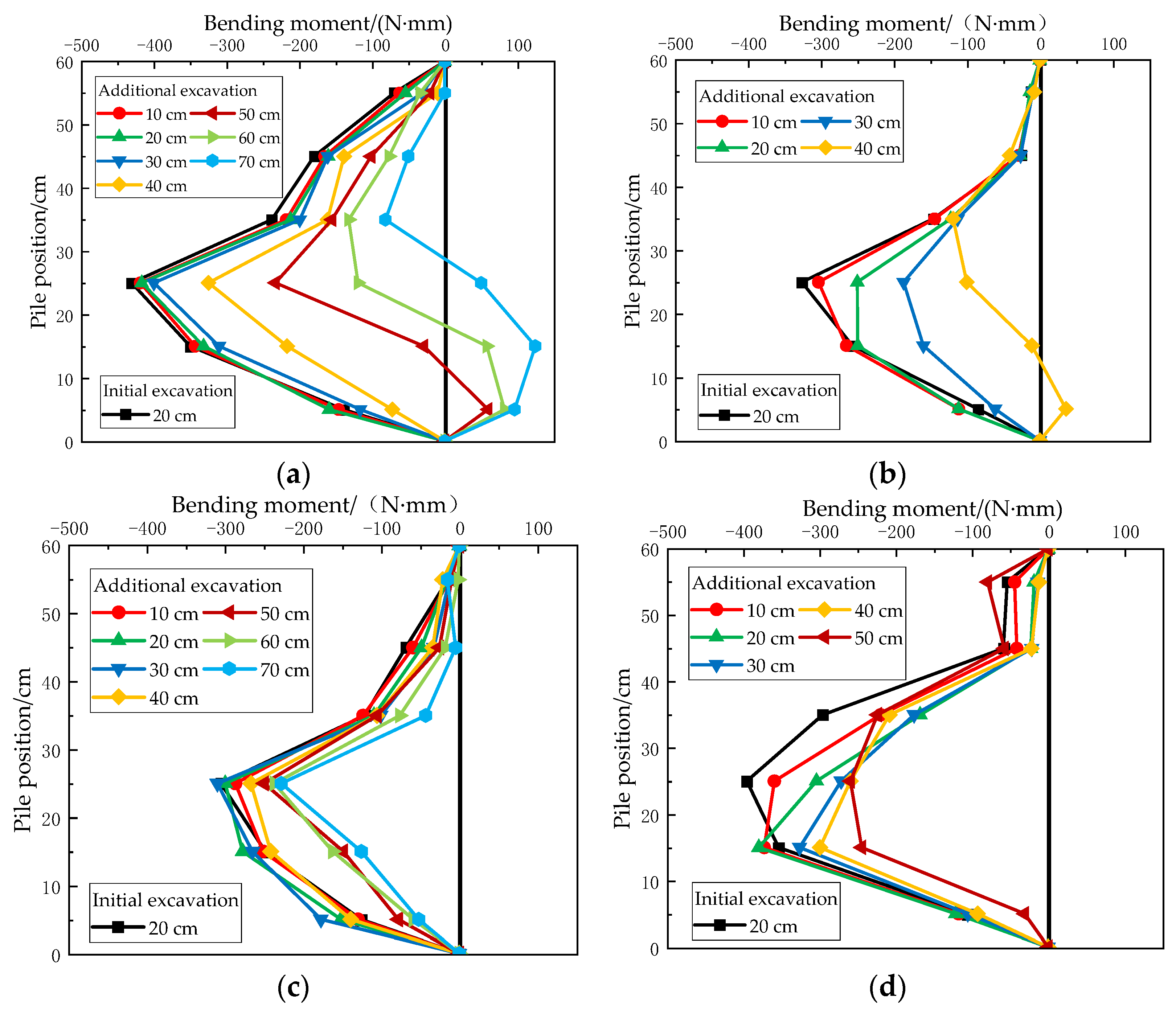
- In the process of decreasing the pile length ratio (L2/L1), the overall stability of the support system continues to weaken. It can be concluded that the existence of a pile top constraint will make the negative bending moment area and the peak value of the additional support piles decrease as a whole, evolving into a positive bending moment. In addition, it is observed that the state of the whole support system is more stable after increasing the pile top constraint. The existence of the service foundation pile can increase the bending moment of the additional support piles and reduce displacement of the pile top;
- The study verified the rationality of the model test results according to the numerical simulation and calculated the stability of the double-row piles support system. It can be seen that the overall stability and safety of deep excavation decrease with the increase of excavation depth, which is easily damaged by external interference;
- The influence of service foundation piles on the double-row pile support system is related to many factors, including the number of foundation piles, layout of foundation piles, size design of foundation piles, distance between foundation piles and retaining wall, and the load on the pile top. Currently, research on the influencing effect of parameter adjustments is lacking, and more work needs to be carried out on this topic. Research work based on this issue is, in our opinion, a worthwhile direction.
Author Contributions
Funding
Acknowledgments
Conflicts of Interest
References
- Shanghai Housing and Urban-Rural Construction Management Committee. The Code for the Conversion and Extension of Existing Underground Buildings in Shanghai; Shanghai Housing and Urban-Rural Construction Management Committee: Shanghai, China, 2017. (In Chinese)
- Ooi, P.S.K.; Chang, B.K.F.; Wang, S.H. Simplified lateral load analyses of fixed-head piles and pile groups. J. Geotech. Geoenviron. Eng. 2004, 130, 1140–1151. [Google Scholar] [CrossRef]
- Masatoshi, M. Lateral behavior of a double sheet pile wall structure. Soils Found. 1974, 14, 45–59. [Google Scholar] [CrossRef] [Green Version]
- Zheng, X.; Zhu, W.X.; Zhou, Y.J. Model tests study on deformation mechanism of double-row-piles wall. J. Build. Struct. 2018, 48, 763–767. (In Chinese) [Google Scholar]
- Han, X.S.; Ren, D.; Li, J.H.; Feng, L.M. Application of self-sustaining double-row piles in bracing of foundation pits of underground parking garages. J. Geotech. Eng. 2010, 32, 275–279. (In Chinese) [Google Scholar]
- Lian, F.; Liu, Z.; Fu, J.; Gong, X.; Li, X.; Gong, X. Case study of double-row-pile wall. J. Geotech. Eng. 2014, 36, 127–131. (In Chinese) [Google Scholar]
- Taiyari, F.; Kharghani, M.; Hajihassani, M. Optimal design of pile wall retaining system during deep excavation using swarm intelligence technique. Structures 2020, 28, 1991–1999. [Google Scholar] [CrossRef]
- Ayasrah, M.; Qiu, H.; Zhang, X. Influence of Cairo Metro Tunnel Excavation on Pile Deep Foundation of the Adjacent Underground Structures: Numerical Study. Symmetry 2021, 13, 426. [Google Scholar] [CrossRef]
- Iwasaki, Y.; Watanabe, H.; Fukuda, M.; Hirata, A.; Hori, Y. Construction control for underpinning piles and their behavior during excavation. Géotechnique 1994, 44, 681–689. [Google Scholar] [CrossRef]
- Poulos, H.G.; Chen, L.T. Pile response due to excavation-induced lateral soil movement. J. Geotech. Geoenviron. Eng. 1997, 123, 94–99. [Google Scholar] [CrossRef]
- Yu, F.; Liu, N.W.; Fang, K. Excavation-induced behavior of a retaining structure using double-rowed micropiles in soft clay. J. Rock Mech. Eng. 2013, 32, 4139–4148. (In Chinese) [Google Scholar]
- Tang, D.Q.; Yu, F.; Chen, Y.T.; Liu, N.W. Model excavation tests on double layered retaining structure composed of existing and supplementary soldier piles. J. Rock Soil Mech. 2019, 40, 1–10. (In Chinese) [Google Scholar]
- Yang, K.H.; Liu, C.N. Finite element analysis of earth pressure for narrow retaining walls. J. GeoEng. 2007, 2, 43–52. [Google Scholar] [CrossRef]
- Fan, C.C.; Fang, Y.S. Numerical solution of active earth pressures on rigid retaining walls built near rock faces. Comput. Geotech. 2010, 37, 1023–1029. [Google Scholar] [CrossRef]
- Jaccaz, S.L.; De Matos, Y.M.P.; Monteiro, F.F.; Cunha, R.P.; Ruge, J.C.; Gassler, G. Evaluation of analytical and numerical techniques to simulate curtain pile walls in a tropical soil of the federal district of Brazil. Geotech. Eng. 2020, 51, 30–38. [Google Scholar]
- Brouthen, A.; Houhou, M.N.; Damians, I.P. Numerical Study of the Influence of the Interaction Distance, the Polymeric Strips Pre-Tensioning, and the Soil–Polymeric Interaction on the Performance of Back-to-Back Reinforced Soil Walls. Infrastructures 2022, 7, 22. [Google Scholar] [CrossRef]
- Singh, A.P.; Chatterjee, K. Ground Settlement and Deflection Response of Cantilever Sheet Pile Wall Subjected to Surcharge Loading. Indian Geotech. J. 2020, 50, 540–549. [Google Scholar] [CrossRef]
- Liu, Q.S.; Fu, J.J. Research on model and parameters of double-row piles based on effect of pile-soil contact. J. Rock Soil Mech. 2011, 32, 481–494. (In Chinese) [Google Scholar]
- Fang, C.F.; Chu, Z.H. Calculation and analysis of double-row piles support structure in deep excavation of limited soil. J. Geotech. Eng. Tech. 2014, 28, 100–105. (In Chinese) [Google Scholar]
- Issa, U.; Saeed, F.; Miky, Y.; Alqurashi, M.; Osman, E. Hybrid AHP-Fuzzy TOPSIS Approach for Selecting Deep Excavation Support System. Buildings 2022, 12, 295. [Google Scholar] [CrossRef]
- Oliveira, F.; Fernandes, I. Influence of geotechnical works on neighboring structures. In Proceedings of the 17th International Multidisciplinary Scientific GeoConference: SGEM, Vienna, Austria, 27–29 November 2017; Volume 12, pp. 993–1001. [Google Scholar] [CrossRef]
- Sainea-Vargas, C.J.; Torres-Suárez, M.C. Damage probability assessment for adjoining buildings to deep excavations in soft soils. J. Geotech. Eng. 2020, 14, 793–808. [Google Scholar] [CrossRef]
- Aswathy, M.S.; Vinoth, M.; Mittal, A.; Behera, S. Prediction of Surface Settlement Due to Deep Excavation in Indo-Gangetic Plain: A Case Study. Indian Geotech. J. 2020, 50, 620–633. [Google Scholar] [CrossRef]
- Mitew-Czajewska, M. FEM modelling of deep excavation—Parametric study, Hypoplastic Clay model verification. Matec Web Conf. 2017, 117, 00121. [Google Scholar] [CrossRef] [Green Version]
- Szabowicz, H.; Żyrek, T. Strutting systems for deep excavations—Technical challenges. IOP Conf. Ser. Mat. Sci. Eng. 2018, 365, 042066. [Google Scholar] [CrossRef]
- Dmochowski, G.; Szolomicki, J. Technical and Structural Problems Related to the Interaction between a Deep Excavation and Adjacent Existing Buildings. Appl. Sci. 2021, 11, 481. [Google Scholar] [CrossRef]
- Mitew-Czajewska, M. A study of displacements of structures in the vicinity of deep excavation. Arch. Civ. Mech. Eng. 2019, 19, 547–556. [Google Scholar] [CrossRef]
- Bryson, L.S.; Zapata-Medina, D.G. Method for estimating system stiffness for excavation support walls. J. Geotech. Geoenviron. Eng. 2012, 138, 1104–1115. [Google Scholar] [CrossRef]
- Fourie, A.B.; Potts, D.M. Comparison of finite element and limiting equilibrium analyses for an embedded cantilever retaining wall. Géotechnique 1989, 39, 175–188. [Google Scholar] [CrossRef]
- Lam, S.Y.; Haigh, S.K.; Elshafie, M.Z.E.B.; Bolton, M.D. A new apparatus for modelling excavations. Int. J. Phys. Model. Geotech. 2012, 12, 24–38. [Google Scholar] [CrossRef] [Green Version]
- Leung, C.F.; Chow, Y.K.; Shen, R.F. Behavior of pile subject to excavation-induced soil movement. J. Geotech. Geoenviron. Eng. 2000, 126, 947–954. [Google Scholar] [CrossRef]
- Ooi, P.S.K.; Ramsey, T.L. Curvature and bending moments from inclinometer data. Int. J. Geomech. 2003, 3, 64–74. [Google Scholar] [CrossRef]
- Wyjadłowski, M.; Kozubal, J.; Damsz, W. The Historical Earthworks of the Warsaw Citadel. Sustainability 2020, 12, 7695. [Google Scholar] [CrossRef]
- Popielski, P.; Kasprzak, A.; Bednarz, B. Using Thermal Monitoring and Fibre Optic Measurements to Verify Numerical Models, Soil Parameters and to Determine the Impact of the Implemented Investment on Neighbouring Structures. Sustainability 2022, 14, 4050. [Google Scholar] [CrossRef]
- Bose, S.K.; Som, N.N. Parametric study of a braced cut by finite element method. Comput. Geotech. 1998, 22, 91–107. [Google Scholar] [CrossRef]
- On, C.Y.; Chou, D.C.; Wu, T.S. Three-dimensional finite element analysis of deep excavations. J. Geotech. Eng. 1996, 122, 337–345. [Google Scholar] [CrossRef]
- Liu, J.; Zheng, G.; Nie, D.Q. Parameter analysis on deformation of multi-stage support structure of deep excavation in Tianjin soft soil area. J. Shijiazhuang Tiedao Univ. (Nat. Sci. Ed.) 2018, 31, 47–54. (In Chinese) [Google Scholar]
- Ren, W.D.; Zhang, X.T.; Zhang, D.M.; Li, Y.L.; Zhang, L.; Sun, Y.S.; Zheng, G. Failure mode and stability parameters analysis of multilevel support for deep excavation. J. Geotech. Eng. 2013, 35, 919–922. (In Chinese) [Google Scholar]
- Bolton, M.D.; Powrie, W. The collapse of diaphragm walls retaining clay. Géotechnique 1987, 37, 335–353. [Google Scholar] [CrossRef]
- Moormann, C. Analysis of wall and ground movements due to deep excavations in soft soil based on a new worldwide database. Soils Found. 2004, 44, 87–98. [Google Scholar] [CrossRef] [Green Version]
- Osman, A.S.; Bolton, M.D. A new design method for retaining walls in clay. Can. Geotech. J. 2004, 41, 451–466. [Google Scholar] [CrossRef]
- Zhejiang Urban Construction and Architectural Design Institute. Design Paper of Zhejiang Hotel Expansion Project; Zhejiang Urban Construction and Architectural Design Institute: Hangzhou, China, 1996. (In Chinese) [Google Scholar]
- Li, D.P.; Tang, D.G.; Yan, F.G.; Huang, M. Mechanics of deep excavation’s spatial effect and soil pressure calculation method considering its influence. J. Zhejiang Univ. (Eng. Sci.) 2014, 48, 1632–1639. (In Chinese) [Google Scholar]
- Yu, F.; Xie, Z.B.; Duan, N.; Liu, N.W.; Shan, H.F. Performance of double-row piles retaining excavation beneath existing underground space. Int. J. Phys. Model. Geotech. 2019, 19, 167–180. [Google Scholar] [CrossRef]
- Ghadrdan, M.; Shaghaghi, T.; Tolooiyan, A. Sensitivity of the stability assessment of a deep excavation to the material characterisations and analysis methods. Geomech. Geophys. Geo-Energy Geo-Resour. 2020, 6, 59. [Google Scholar] [CrossRef]


| Description / | Unit Weight ρ: g/cm3 | Water Content ω: % | Cohesion c: kPa | Friction Angle Φ: deg |
|---|---|---|---|---|
| Silt | 15.8 | 5 | 2 | 24 |
| Number | L1 | L2 | h | D | Existing Excavation | Additional Excavation |
|---|---|---|---|---|---|---|
| T1 | 65 | 105 | 20 | 4d | 20 | 10 × n |
| T2 | 65 | 105 | 20 | 6d | 20 | 10 × n |
| T3 | 65 | 105 | 20 | 8d | 20 | 10 × n |
| T4 | 65 | 105 | 20 | 10d | 20 | 10 × n |
| T5 | 65 | 105 | 20 | 12d | 20 | 10 × n |
| T6 | 65 | 105 | 20 | 4d | 20 | 10 × n |
| T7 | 0 | 105 | / | / | 0 | 10 × n |
| T8 | 65 | 0 | / | / | 20 | 10 × n |
| Number | L1 | L2 | h | D | P(N) | Pile Top Constraint | Existing Excavation | Additional Excavation |
|---|---|---|---|---|---|---|---|---|
| N1 | 65 | 125 | 20 | 6d | 240 | NO | 20 | 10 × n |
| N2 | 65 | 105 | 20 | 6d | 240 | NO | 20 | 10 × n |
| N3 | 65 | 85 | 20 | 6d | 240 | NO | 20 | 10 × n |
| N4 | 65 | 65 | 20 | 6d | 240 | NO | 20 | 10 × n |
| N5 | 65 | 105 | 20 | 6d | 240 | YES | 20 | 10 × n |
| N6 | 65 | 65 | 20 | 6d | 240 | YES | 20 | 10 × n |
| Parameter | γunsat | E50ref | Eoedref | Eurref | C | φ | γ0.7 | G0ref | Rinter |
|---|---|---|---|---|---|---|---|---|---|
| Value | 15.8 | 6000 | 3000 | 18 × 103 | 2 | 24 | 1 × 10⁻³ | 54 × 103 | 0.7 |
Publisher’s Note: MDPI stays neutral with regard to jurisdictional claims in published maps and institutional affiliations. |
© 2022 by the authors. Licensee MDPI, Basel, Switzerland. This article is an open access article distributed under the terms and conditions of the Creative Commons Attribution (CC BY) license (https://creativecommons.org/licenses/by/4.0/).
Share and Cite
Xiao, Y.; Wang, X.; Yu, F.; Wang, Z. Experimental Investigation of h-Type Supporting System for Excavation beneath Existing Underground Space. Buildings 2022, 12, 635. https://doi.org/10.3390/buildings12050635
Xiao Y, Wang X, Yu F, Wang Z. Experimental Investigation of h-Type Supporting System for Excavation beneath Existing Underground Space. Buildings. 2022; 12(5):635. https://doi.org/10.3390/buildings12050635
Chicago/Turabian StyleXiao, Yang, Xiangge Wang, Feng Yu, and Zijun Wang. 2022. "Experimental Investigation of h-Type Supporting System for Excavation beneath Existing Underground Space" Buildings 12, no. 5: 635. https://doi.org/10.3390/buildings12050635
APA StyleXiao, Y., Wang, X., Yu, F., & Wang, Z. (2022). Experimental Investigation of h-Type Supporting System for Excavation beneath Existing Underground Space. Buildings, 12(5), 635. https://doi.org/10.3390/buildings12050635