Abstract
The in-plane seismic performance of old unreinforced brick masonry walls strengthened with stainless-steel twisted bars and conventional steel bars (usually used in concrete reinforcing) was investigated in the present study. For this purpose, a total of seventeen masonry wallettes reproducing masonry walls of traditional Lisbon buildings from the 1930s–1950s (known as “placa” buildings) were constructed. The specimens were assembled using original bricks from demolished old buildings and a sand-cement bedding mortar with the same proportions as reported in building design documents of the time. Out of the fourteen wallettes tested in diagonal compression, three were unreinforced, and eleven were strengthened in different layouts. Additionally, axial compression tests were performed on the other three unreinforced masonry wallettes. The tested specimens were reproduced with numerical models calibrated based on the experimental results. The experimental and numerical results of the reinforced specimens were compared to the unreinforced specimens to draw conclusions on the effectiveness of the strengthening solutions when applied to masonry walls of the typology under study. The most important result of the strengthening was an important increase in the ductility of the specimens that were originally brittle. In addition, in some cases a slight increase of shear strength was also observed.
1. Introduction
There are many and significant reasons for the preservation of buildings and their rehabilitation, rather than their demolition and reconstruction. The heritage value of buildings is only one of these reasons. Currently, sustainability concerns point to an increasing reuse of buildings, thus reducing waste, littering, and energy consumption. With this purpose, the improvement of the structural performance of old constructions is a very important issue as they normally do not comply with present structural codes, particularly in what concerns their seismic behavior.
Many recent earthquakes have proved that traditional masonry structures are very vulnerable when subjected to seismic loads [1,2,3]. The low shear strength and its brittle behavior are the main factors of this susceptibility. Design rules for masonry buildings are presently specified in structural codes, such as Eurocodes 6 [4] and 8 [5]. However, those rules were not followed in the design of old masonry buildings, thus proper seismic strengthening solutions are needed for this type of structures.
The evolution of the construction process of historic masonry buildings over time and their relation to the historical and socio-economic context are also necessary aspects to be taken into consideration. As valuable examples of modernism or art deco these buildings may have significant cultural value, as they identify and represent a specific era and architectural style. The potential loss of this type of heritage means not only a physical loss in terms of quality of life, but also a loss of collective memory, citizenship, and a sense of belonging to the locals. Heritage is responsible for the transmission of knowledge and cultural values to future generations, enabling as such both the historical continuity of people and their cultural identity. In addition, it creates unique personalities for each urban/rural settlement, and favors the orientation and enjoyment of public and semi-public spaces. As such, it is imperative to preserve this heritage by taking real and effective structural protective measures.
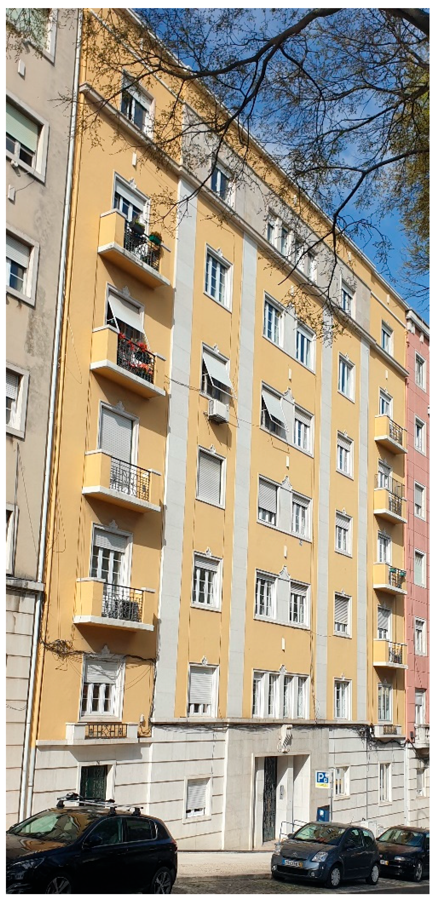
The overall behavior of old masonry structures is complex, since it highly depends on the masonry units, the bedding mortar, and the mortar-unit interface. Consequently, studies are required to characterize these materials and the structural behavior of the elements, and to evaluate the effectiveness of seismic strengthening solutions suitable for these buildings. In this regard, the project “RESIST-2020—Seismic Rehabilitation of Old Masonry-Concrete Buildings” focuses on the seismic behavior of solid clay brick masonry walls used in the structural arrangement of old masonry-concrete buildings. These buildings’ typology was widely used in Europe during the transition period from masonry to reinforced concrete, which took place between the 1930s and the 1950s [6,7]. In Portugal these transitional buildings (known as “placa” buildings, where “placa” means “slab”, as opposite to timber floors—Figure 1) are characterized by thin reinforced concrete slabs resting on load-bearing walls made of solid clay brick, perforated clay brick or irregular stones. These units (bricks, stones) were initially bonded together with a hydrated lime mortar, while in the latter stages of that period, mixed cement-lime-sand or simple cement-sand mortars were used. These buildings show homogeneous planned areas with non-excessive dimensions, and the number of stories rarely gets above five [8].

Figure 1.
Exterior view of a “Placa” building in Lisbon, Portugal.
Some techniques for the reinforcement of solid clay brick masonry walls have been developed and studied in the last few years, some of them through experimental tests, among which, reinforced plasters [9], FRCM and FRM composites [10], ECC shotcrete [11], GFRP jacketing [12], and NSM steel bars [13,14]. All of them have advantages from a structural point of view, but not all are practical or economical from a construction practice point of view. Table 1 summarizes test results of other works studying the shear strength of masonry walls.

Table 1.
Shear strength through diagonal compression test of URM and strengthened masonry walls in literature [13,15,16,17,18,19,20,21,22,23].
In this study a strengthening solution is proposed to address the deficiencies of masonry walls made of solid clay brick in terms of tensile and shear strength and ductility. The proposed solution consists of using near surface mounted (NSM) twisted steel bars (TSB) or conventional concrete reinforcing steel bars (CSB), embedded inside slots (opened on purpose) using premix mortar. The NSM technique has a minimal effect on the architectural aspect, and the helical shape of TSB provides considerable anchorage of reinforcement even in shorter embedded lengths.
The solution proposed, although requiring a significant preparation of the surfaces (opening of slots), is feasible and applicable, with reasonable execution costs. The application of the strengthening only on the inside face of the walls—with connection of the TSB to the floor slabs or crossing these slabs establishing continuity between the walls of the various floors—is one of the options to be considered, since in many cases it may be difficult to intervene on the outside faces of the facades.
After the reinforcement is applied, the walls will be plastered, stuccoed, and painted, as usual in this type of construction.
The walls studied in this research were executed with cement-based mortars with a cement-sand ratio of 1:5, in accordance with the technical specifications of some buildings in Lisbon. As its composition corresponds to a “strong” mortar, the walls’ mortar joints have a high resistance to compression and tension, unlike the masonry walls of older buildings made with lime mortars, with lower resistance and cohesion.
The brick walls with a cement-based mortar addressed in the present study have been little studied until now. Nevertheless, strengthening solutions developed for other types of (weaker) brick walls have been adopted to their reinforcement, with so far unknown results.
To this study, three masonry assemblages (wallettes) of 76 × 76 × 25 cm3 and fourteen wallettes of 86 × 86 × 25 cm3 were constructed using original solid clay bricks from demolition works of an old building in the city center of Lisbon. A cement-based mortar with a 1:5 cement:sand volumetric ratio was used in the construction of the wallettes. The mortar composition was based on the information available at the Municipal Archive of Lisbon [24] relative to a building at the city center. As in the original walls, a Flemish bond was adopted in the construction of the wallettes. A total of six wallettes received no reinforcement, whereas various reinforcement layouts were applied to eleven assemblages. Axial compression tests on three wallettes and diagonal compression tests on fourteen wallettes were carried out.
The masonry assemblages were numerically modelled and calibrated using the experimental test results.
2. Experimental Program
Aiming at investigating the in-plane seismic performance of brick masonry walls, 17 masonry wallettes were constructed and tested at the National Laboratory of Civil Engineering, Lisbon, Portugal. The specimens were built using solid clay bricks and a cement-based mortar of 1:5 cement:sand ratio (by volume).
2.1. Material Testing
Unreinforced and reinforced masonry assemblages were constructed by experienced masons using traditional techniques, with the aim of simulating the behavior of the original walls (built at the time). Both types used solid clay bricks of 230 × 110 × 70 mm3 from the demolition works of an old building in the center of Lisbon.
2.1.1. Brick Properties
The brick compressive strength was experimentally determined based on the EN 772-1 standard [25], where a gradually increasing load was applied at a speed of 10 kN/s (based on the expected compressive strength). The conditioning factor mc = 1.00 has been taken for the air-dried bricks, whereas a shape factor δ = 0.85 was considered based on the brick dimensions (Table 2).
Table 2.
Mean values of compressive strength and static modulus of elasticity of original old bricks.
2.1.2. Bedding Mortar Properties
The bedding mortar composition followed the documentation obtained in the Municipal Archive of Lisbon relative to a 1946 building, with a cement:sand ratio of 1:5 (by volume). The mortar was prepared using this ratio, with 1/3 volume of sandpit sand and 2/3 volume of river sand (also by volume).
Mortar specimens were prepared and tested for flexural and compressive strength based on the standard EN1015-11 [26]. Nine specimens of 160 × 40 × 40 mm3 were tested at 28, 128, and 180 days of age. The mean values of the flexural and compressive strength tests are summarized in Table 3.
Table 3.
Mean values of flexural and compressive strength test results of the bedding mortar.
Specimens from the bedding mortar of some of the wallettes were extracted and tested for compressive strength. Table 4 shows the mean compressive strength of the seven tested specimens.
Table 4.
Mean compressive strength values of the extracted mortar samples from the constructed wallettes.
2.1.3. Reinforcing Bar Properties
For the strengthening of the masonry assemblages, twisted austenitic stainless steel bars of 6 mm nominal diameter (TSB Φ6) were used in four wallettes, whereas three wallettes were strengthened using conventional concrete reinforcing ribbed steel bars of 12 mm nominal diameter (SB Φ12). The tensile strength test results of the TSBs and SBs used (three specimens for each reinforcing bar type) are presented in Table 5.
Table 5.
Reinforcing bars properties.
2.1.4. Embedding Grout Properties
In terms of embedding grout, used to fill the slots where the reinforcement rebars are placed, the provided premixed mortar was also tested (three samples for each age) for flexural and compressive strength at 28, 90, and 180 days, with the results presented in Table 6.
Table 6.
Premixed grout properties.
2.2. Masonry Wallettes Fabrication
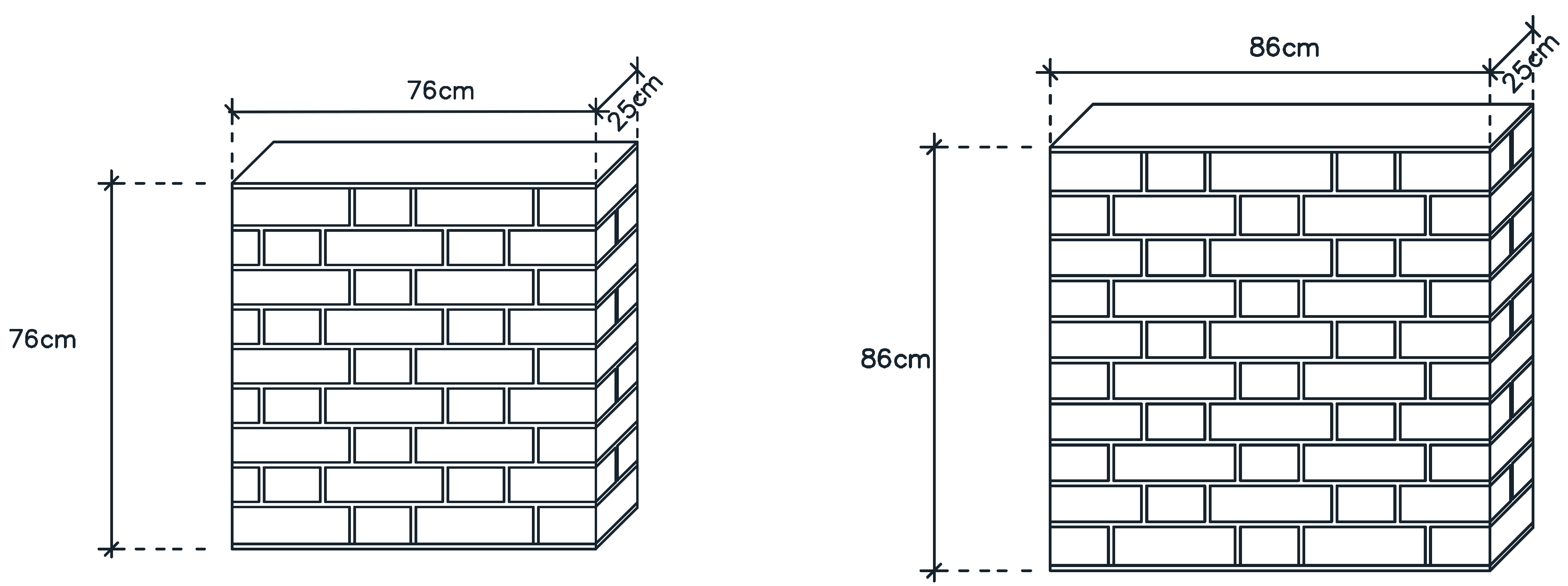
The experimental program involved the fabrication of masonry wallettes and their reinforcement with two different types of steel bars in diverse layouts. Three unreinforced wallettes of 76 × 76 × 25 cm (Type 1) were built for compression tests, whereas fourteen wallettes of 86 × 86 × 25 cm (Types 2, 3 and 4) were built for diagonal compression tests. Table 7 synthetizes the main characteristics of the different wallettes. A Flemish bond, similar to that used in the buildings under study (one header and one stretcher alternately), was used in the execution of the wallettes (Figure 2). The 1:5 (cement:sand) mortar mix was used as bedding mortar with a thickness of 10–15 mm. Three out of the fourteen wallettes were built with no reinforcement to be subjected to diagonal compression tests (specimens Type 2).
Table 7.
Specimen details.
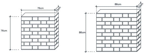
Figure 2.
Unreinforced masonry wallette ((left) Type 1; (right) Types 2 to 4).
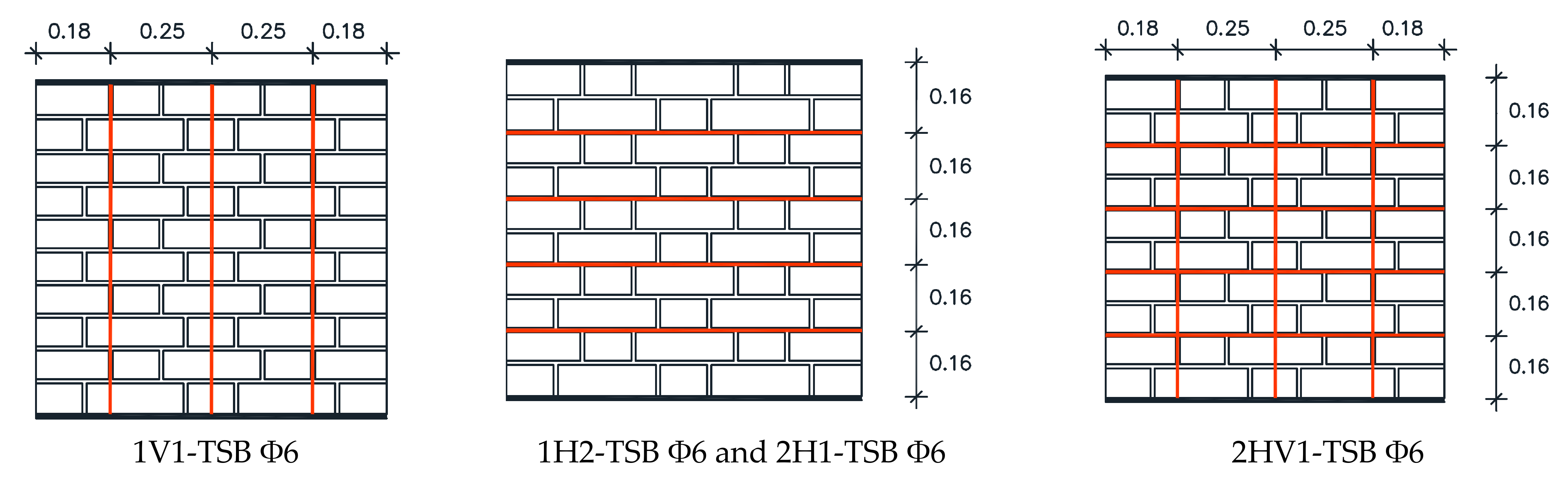
Four types of reinforcement layout were applied to the masonry wallettes reinforced with Φ6 mm TSB (specimens Type 3): vertically only with reinforcement in one face; horizontally only with reinforcement in one or in two faces; and grid type (vertical and horizontal) with reinforcement in two faces (Figure 3). Since, in certain practical application situations, it may be difficult, or even unfeasible, to reinforce both faces of the walls, the performance of reinforcement solutions applied on a single face was also needed. In particular, it was sought to know whether equivalent results could be obtained by reinforcing on only one face, by doubling the reinforcement on that face. With this objective, the “horizontal with reinforcement in only one face” layout had two bars per slot. Two specimens of each layout were built and tested.
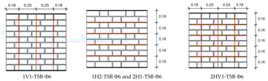
Figure 3.
Specimen reinforcement layout with Φ6 mm TSB (Type 3).
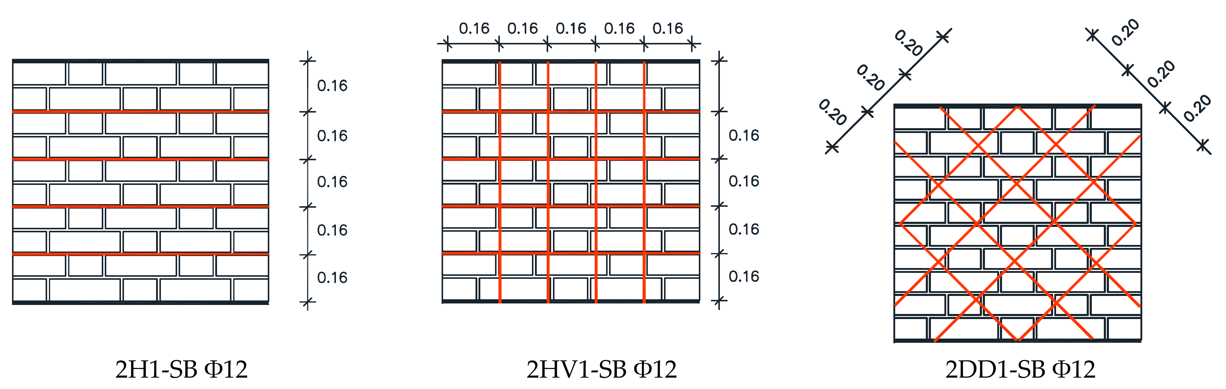
The three wallettes reinforced with Φ12 mm concrete reinforcing steel rebars (specimens Type 4) include horizontal only, grid, and ortho-diagonal reinforcement (Figure 4). Details on the reinforcement layout are provided in Table 6.
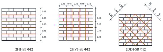
Figure 4.
Specimen reinforcement layout with Φ12 mm steel rebars (Type 4).
2.3. Reinforcement of Wallettes
The reinforcement of the masonry wallettes consists in cutting slots wide and deep enough to accommodate the NSF of steel bars bonded with the injectable grout. Initially, 25 mm wide and 25 mm deep slots for Type 2 and 40 mm wide and 40 mm deep for Type 3 wallettes were cut. The bars were cut with the length corresponding to the reinforcement layout. To simulate a proper bar adhesion and anchoring in real applications (due to its length or to proper constructive detailing), the bars’ extremities were bent to run horizontally through the thickness of the wallette within a cut slot. The injectable grout was placed in two phases: firstly, a layer of premixed mortar was applied through a “syringe”, then the bar was inserted in the slot and pushed against that mortar layer; next, the same premixed grout was applied until fulfilling the slot; finally, the mortar was compressed and finished with a proper tool.
2.4. Tests’ Set-Up and Procedures
To investigate the compressive and shear strength and of the masonry wallettes two types of tests were performed, namely, axial compression tests, and diagonal compression tests.
2.4.1. Axial Compression Tests
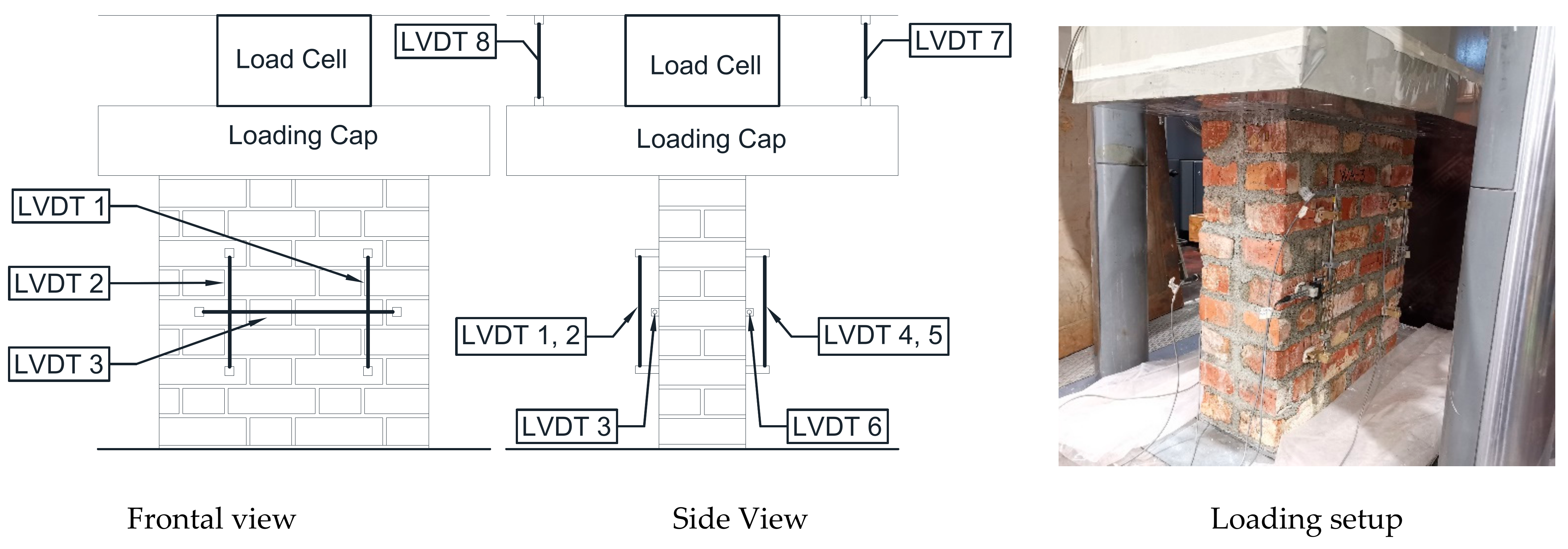
Axial compression tests were carried out following the provisions of the standard EN 1052-1 [27]. A vertical displacement at a rate of 0.005 mm/s was applied to the specimen through the loading cap of an MFL press with 5000 kN capacity. Eight LVDT displacement transducers were used to measure the deformation (Figure 5). Four LVDTs (LVDT 1, 2, 4, and 5), two on each side, were placed to measure the vertical shortening of the specimen, whereas two LVDTs (LVDT 3 and 6), placed horizontally on both sides of the wallette, measured the horizontal deformation of the specimen. The displacement of the loading cap, measured with the other two LVDTs, one on each side (7 and 8), allows to continue measuring overall vertical deformation after the removal of the LVDTs from the wallette to avoid damage in the final test stages.
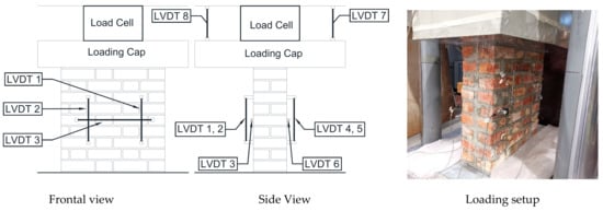
Figure 5.
Location of the LVDTs on the masonry wallettes for Axial Compression Tests.
The tests were stopped when the vertical load applied reached one fifth of the maximum load achieved.
2.4.2. Diagonal Compression Tests
Diagonal compression tests were carried out following the standard ASTM 519/519M-10 [28] and other experimental works alike (Table 1). The specimens prior to instrumentation were rotated by 45° and placed on two identical steel shoes for the vertical load application. The same load cell used in the axial compression test was used to apply a displacement-controlled force on the top vertex of the wallette at a rate of 0.005 mm/s. Six LVDTs were used to measure the deformation of wall specimens (Figure 6). Two LVDTs (LVDT A and C) were placed on each side of the wallette to measure the shortening of the specimen in a vertical direction. Another two LVDTs (LVDT B and D) were placed to measure the elongation of the specimen in horizontal direction. The load cell cap displacement was additionally logged via two LVDTs placed on each side of the load cap (LVDT E and F). Given that upon the appearance of the first cracks the LVDTs on the wallette were removed for safety reasons, the vertical displacement is ensured through the readings obtained through LVDT E and F. The loading continued until the vertical load applied at the vertex along the diagonal reached one fifth of the ultimate load.
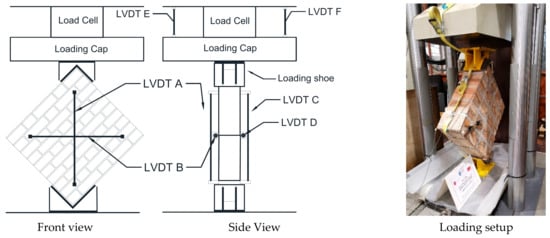
Figure 6.
Instrumented wallette specimen for diagonal compression test.
3. Experimental Test Results and Analysis
3.1. Axial Compression Tests
Test Results—Type 1 Wallettes (Unreinforced)
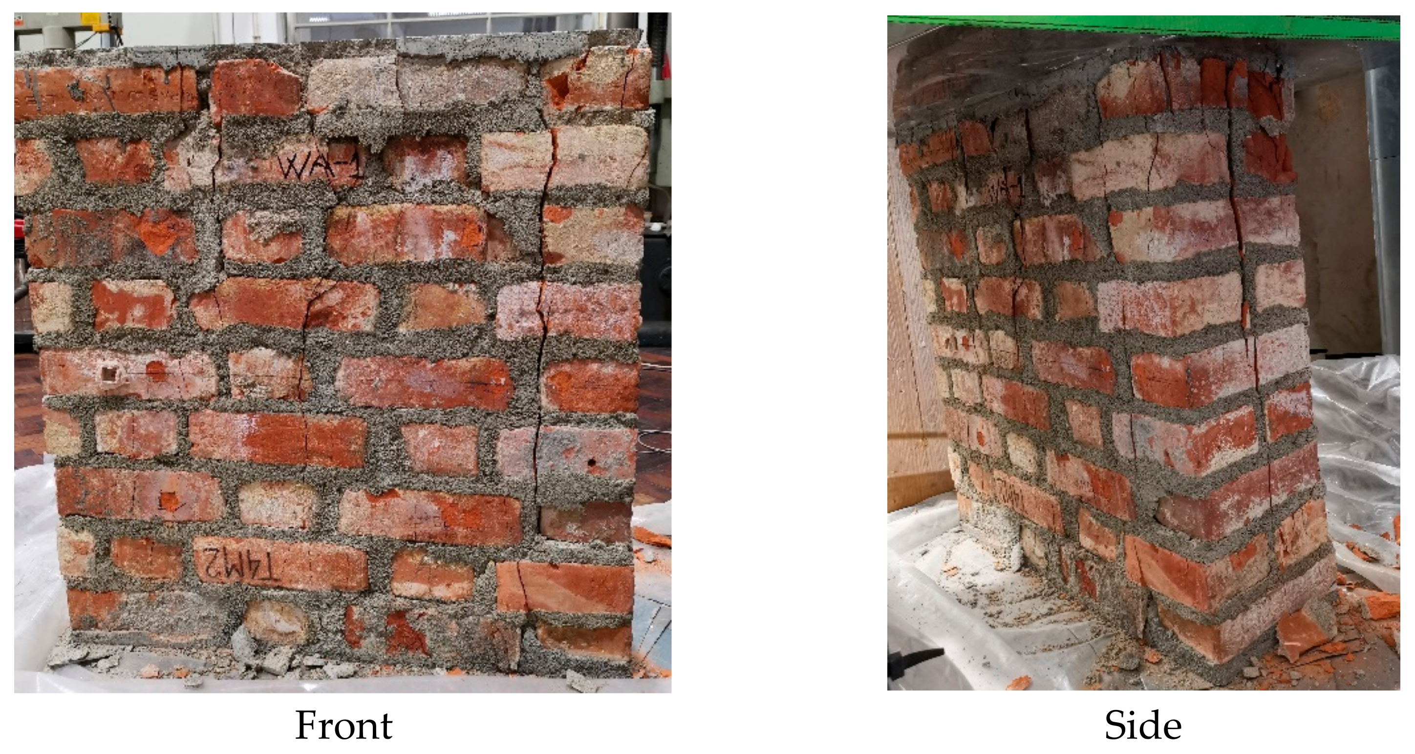
The compressive strength and the modulus of elasticity were calculated according to the standard EN 1052-1 [27]. All the three unreinforced (Type 1) wallettes tested under uniaxial compression reached failure through the same mechanism: vertical cracks appeared on both faces of the allette, which in turn were accompanied by vertical cracks on the sides due to the separation of the wythes. Figure 7 shows the crack patterns after the axial compression test.
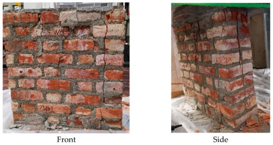
Figure 7.
Crack patterns after the axial compression test.
The axial compression test continued until failure, however, the LVDTs were removed when cracks started to appear to prevent their damage. After this point only the vertical displacement was measured through the LVDTs located on top of the load cap.
The values of compressive strength and modulus of elasticity obtained in the tests are shown in Table 8.
Table 8.
Maximum force, maximum stress, and modulus of elasticity of unreinforced wallettes under axial compression test.
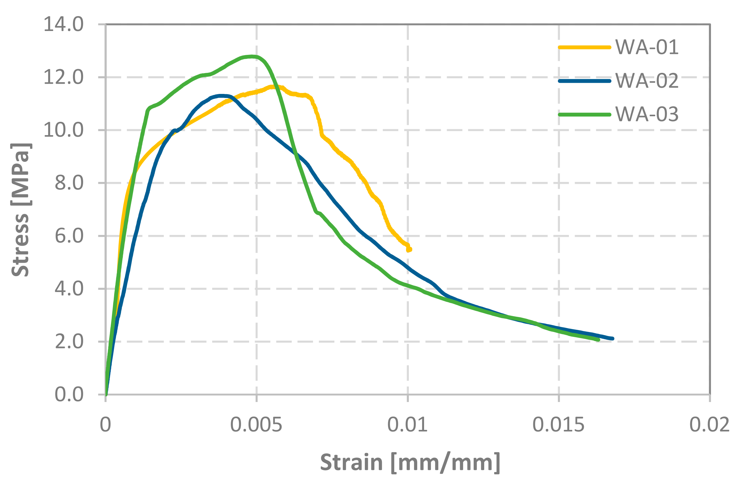
The stress-strain relationships plotted in Figure 8 indicate that all the unreinforced wallettes behaved similarly under the axial compression load. The same is also observed in the values presented in Table 8.
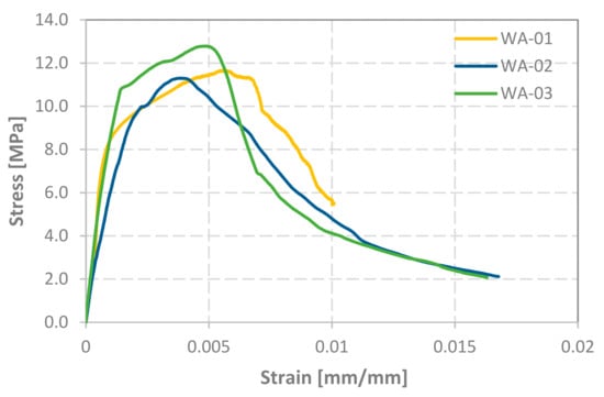
Figure 8.
Stress-strain plots of axial compression test for each wallette.
As expected, the stress-strain diagram is initially linear until it reaches the yield stress. Then it is followed by a stress hardening curve until the ultimate stress, beyond which a parabolic softening curve develops with a decreasing slope.
3.2. Diagonal Compression Tests
3.2.1. Test Results—Type 2 Wallettes (Unreinforced)
The specimens Type 2, Type 3, and Type 4 (Table 7) were subjected to a diagonal compression test, and the modulus of rigidity (or shear modulus) and shear strain are calculated according to the standard ASTM 519/519M-10 [28].
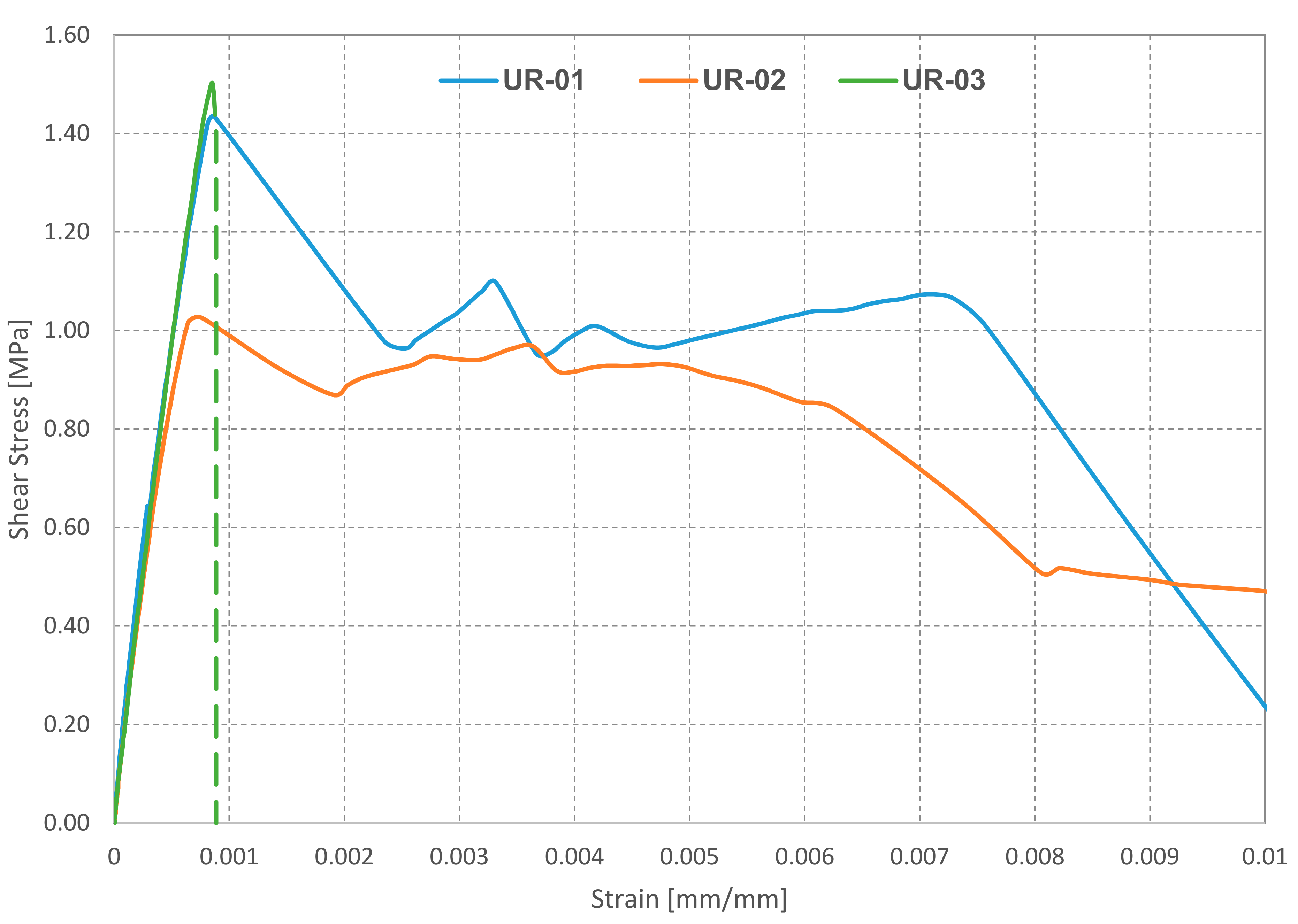
The unreinforced masonry wallettes UR-01, UR-02, and UR-03 exhibited a linear behavior until the ultimate load. Diagonal cracking failure occurred on the three specimens at relatively low strains (Figure 9).
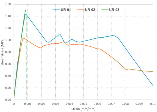
Figure 9.
Shear stress vs. shear strain response of unreinforced wallettes under diagonal compression test (dotted line represents abrupt deformation without interim readings due to the sudden cracking and splitting apart of the two parts).
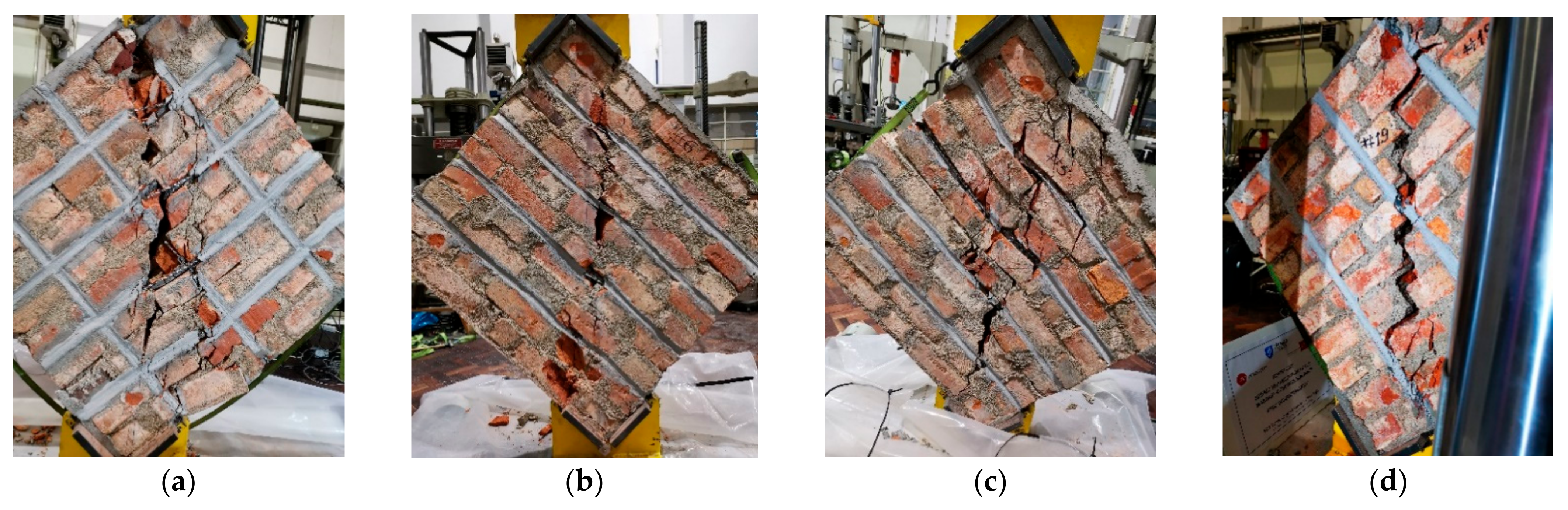
The specimen UR-01, upon reaching the ultimate load, developed the first diagonal crack some centimeters left from the diagonal line of the specimen, followed by a second diagonal crack some centimeters right from the diagonal line of the specimen, creating as such a central strut resisting the vertical load. This phenomenon is traceable in the stress-strain plot (Figure 9), where an increase in shear stress is observed after a considerable shear strain, leading to an increase in the amount of energy absorbed. The sudden drop in the post-peak is connected to brittle failure leading to the separation of the left part (Figure 10a).
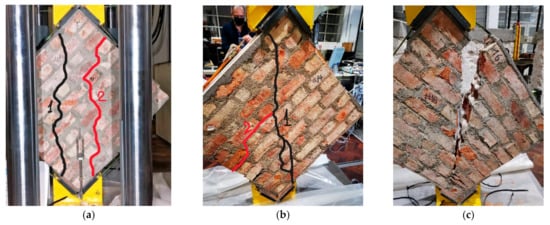
Figure 10.
Crack patterns of the tested unreinforced wallettes. (a) UR-01; (b) UR-02; (c) UR-03.
The wallette specimen UR-02 developed a diagonal crack at the ultimate load, which, after a considerable propagation to the vertices of the specimen, was followed by a second crack originating from the center of the masonry assemblage to the left through a semi-stepped cracking (Figure 10b). This specimen exhibited higher energy absorption at 20% degradation of the ultimate load, since the first crack, which occurred at the peak load, did not propagate entirely throughout the diagonal, allowing the wallette to still carry considerable load.
The specimen UR-03, at its ultimate load, underwent a sudden diagonal cracking (Figure 10c) which is the reason of the missing post-peak interim readings in the stress-strain graph, and the consequent lack of post-peak energy absorption.
The results of the tests in terms of ultimate load, shear strength, modulus of rigidity, and energy absorption are presented in Table 8. The absorbed energy at the ultimate load and at 20% degradation in the ultimate load is the respective area under the stress-strain plots.
As seen in Table 9, the shear strength of this type of wallette is relatively high, reaching a mean value of 1.29 MPa, mainly due to the considerable compressive strength of cement-based mortar. All three specimens have similar modulus of rigidity, a mean value of 2.15 GPa (with an 8.4% COV).
Table 9.
Ultimate load, shear strength, and modulus of rigidity, and energy absorption of Type 2 wallettes.
3.2.2. Test Results—Type 3 Wallettes (Reinforced with Twisted Steel Bars)
Type 3 wallettes were reinforced using 6 mm TSB in four different layouts (two specimens for each layout): three vertical bars only (with reinforcement in one face (1V1)); four horizontal rows only (with reinforcement in one face, but with two bars per slot (1H2); four horizontal bars in both faces with one bar per slot (2H1)); and four horizontal and three vertical bars in each face (2HV1).
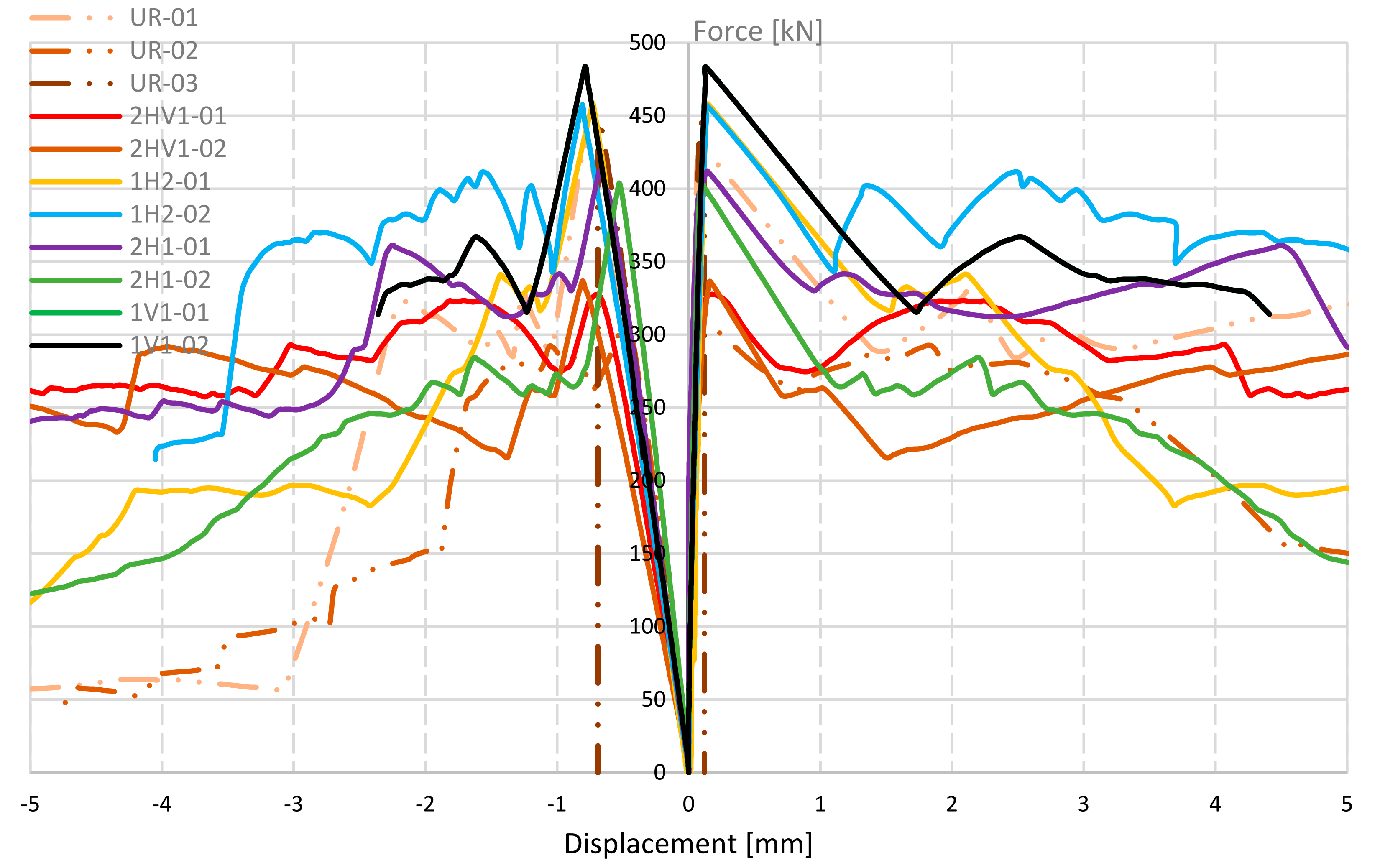
The wallettes reinforced with a horizontal and vertical grid layout, 2HV1-01 and 2HV1-02 (Figure 11a), presented a linear behavior until the ultimate load. Visible cracks appeared only when the load was approaching its peak value (Figure 12). Post-peak behavior is followed by a decrease in the vertical load during the propagation of the diagonal crack. After the wall cracking, the reinforcement bars showed damage due to local bending and shear in the cracks (Figure 12). Apparently, reinforcement bars are not demanded to resist axial tension stresses, which is the mode for which they present the stronger and stiffer mechanical behavior. As a result, there is no increase in the specimen’s strength when compared with the unreinforced specimen. However, the force-displacement diagram shows an increase in ductility (Figure 13). This phenomenon is due to the reinforcement bars that bridge the cracks partially preventing their opening, and leading to an increase in beneficial friction between the cracked parts. At a considerable degradation of the ultimate load some of the central bars fail in shear. In terms of the ultimate load and shear strength (Figure 14a,b, respectively), 2HV1 specimens performed less well than the other Type 3 wallettes (Table 10). However, in terms of energy absorption at 20% degradation of the ultimate load, this reinforcement layout showed an improvement of 167% when compared to the unreinforced masonry wallettes.
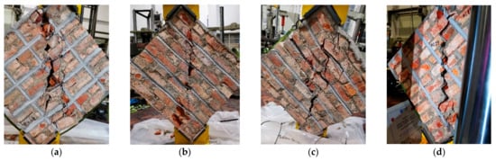
Figure 11.
Crack patterns of the wallettes reinforced with TSB in diagonal compression test. (a) 2HV1-01; (b) 1H2-01; (c) 2H1-01; (d) 1V1-01.

Figure 12.
Local bending and shear damage of bars.
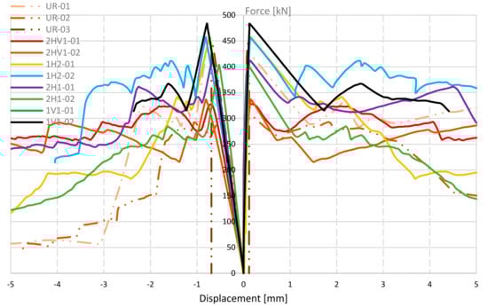
Figure 13.
Force-displacement of TSB reinforced vs. UR wallettes.
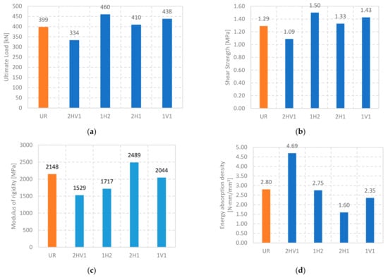
Figure 14.
Wallettes reinforced with TSB vs. unreinforced ones in terms of ultimate load, shear strength, modulus of rigidity, and absorbed energy at 20% force degradation. (a) ultimate load; (b) shear strength; (c) modulus of rigidity; (d) absorbed energy at 20% force degradation.
Table 10.
Ultimate load, shear strength, modulus of rigidity, and energy absorption of Type 3 wallettes.
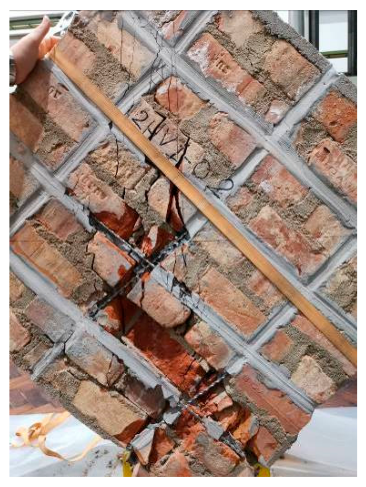
The 1H2 wallettes, with horizontal reinforcement with two bars per slot on one face only, (Figure 11b), behaved linearly up to the ultimate load, then the load decreases due to the first diagonal crack. In terms of ultimate load and related shear strength, there was a slight increase (15%) when compared with the unreinforced specimens. Reinforcement bars showed local bending and shear damages in cracking, and as in the grid layout, they prevented the cracks from opening freely. During the loading an out-of-plane bending of the specimen was observed due to the unsymmetrical reinforcement. Moreover, when compared with the unreinforced specimens, there was no visible contribution to the energy absorption at 20% degradation of the ultimate load (Figure 14d). Similarly, 2H1 wallettes reinforced horizontally on both sides with one TSB per slot (Figure 11c) followed a linear trend until they reached the ultimate load, soon after the first visible diagonal crack appears. In this layout the energy absorption has no increase at all when compared to the unreinforced specimens (Figure 14d), and an irrelevant increase in ultimate load (3%) was observed (Figure 14a,b). No bar rupture was observed in these two layouts.
One side vertical-only reinforcement layout (1V1) showed the same behavior until the peak load. When compared to the unreinforced specimens there was a slight increase in the ultimate load and shear strength (about 10%), while, in terms of energy absorption, no improvement occurred. It is worth mentioning that the central bar was the one most subjected to stresses, since the crack started in the center of the specimen and propagated to the vertices, outside the other bars’ influence zone. The central bar collapsed in shear after a considerable crack opening. No significant damage in the bar due to axial tension was observed. The bond between the bars and masonry provided by the TSB system mortar proved to be very effective in all tests, with no damage occurring outside the cracked zones.
It seems evident that the proposed strengthening has no considerable effect in terms of strength; in one of the cases a decrease in strength was even noted (which may have resulted from the slot opening process that may have weakened the specimen). It is worth mentioning the positive effect in terms of ductility increase in the specimen 2HV1, reinforced in both directions. However, the non-grid reinforcement layouts do not provide sufficient benefit to the masonry, with no significant increase in ductility observed in any specimen reinforced in only one direction. The main reason for the low effectiveness of the solution is the fact that the bars do not work in tension until the moment of the cracking of the specimen, working since then under bending and shear stresses for which they are not efficient.
To evaluate if an increase in the cross section of the reinforcement bars would improve the solution effectiveness, new tests were performed on specimens reinforced with larger diameter bars (12 mm). In this case, since the durability performance was not under study, conventional reinforced concrete bars were used instead of stainless steel bars.
3.2.3. Test Results—Type 4 Wallettes (Reinforced with Concrete Reinforcing Bars)
Three Type 4 wallettes were reinforced using reinforced concrete reinforcing bars of 12 mm nominal diameter (Table 4).
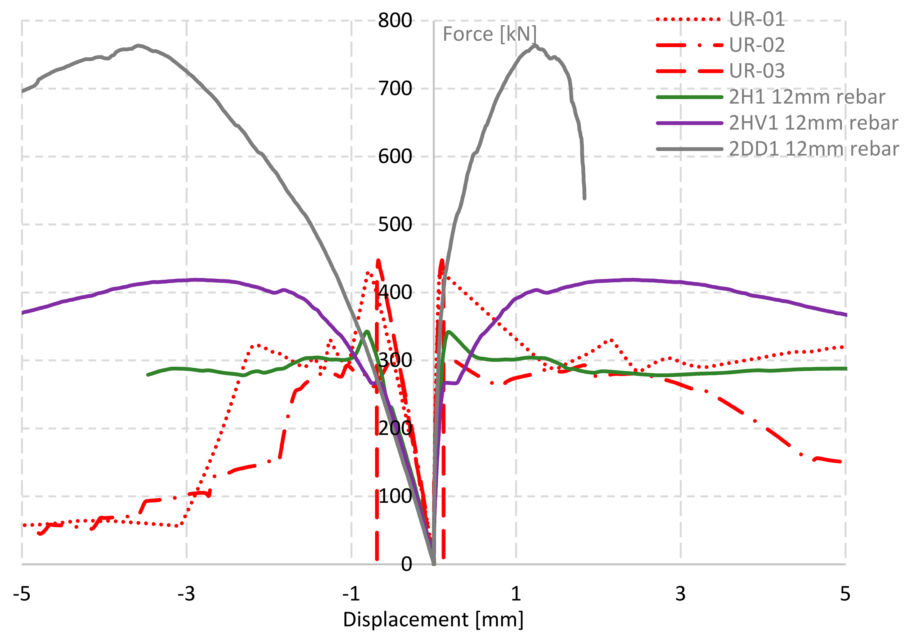
The wallette specimen 2H1 (Figure 15a)—reinforced on both sides, only horizontally, in four rows, with one bar per slot—exhibits an almost linear behavior until the ultimate load (Figure 16). Two parallel diagonal cracks appeared in the central part of the specimen, the right one starting from the top and the left from the bottom vertex, creating a central “strut” which causes the load to be kept constant while the deformation increases. The failure mechanism starts with diagonal cracks opening through the masonry units and continues with sliding in the bed joints, especially in the joint of the second rebar. Upon considerable crushing of the masonry, the upper part slides down, achieving the ultimate failure. The presence of horizontal reinforcement prevents the opening of the diagonal cracks, but the lack of vertical reinforcements causes a sliding along a plane parallel to the existing reinforcement. In terms of ultimate load and shear strength there was no improvement (Figure 17a,b). However, there is a substantial increase in energy absorption at 20% degradation of the ultimate load as shown in Figure 17d.
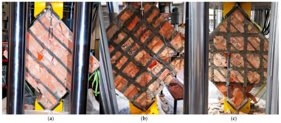
Figure 15.
Crack patterns of the wallettes reinforced with SB in diagonal compression test. (a) 2H1; (b) 2HV1; (c) 2DD1.
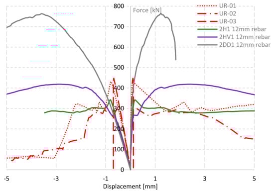
Figure 16.
Force-displacement of SB reinforced vs. UR wallettes.
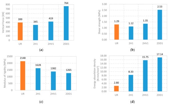
Figure 17.
Wallettes reinforced with SB vs. unreinforced ones in terms of ultimate load, shear strength, modulus of rigidity, and absorbed energy at 20% force degradation. (a) ultimate load; (b) shear strength; (c) modulus of rigidity; (d) absorbed energy at 20% force degradation.
Unlike 2H1, the wallette with the horizontal and vertical grid layout on both sides, 2HV1, exhibited a linear behavior up to approximately 60% of the ultimate load, where the first diagonal crack appeared. The wallette was able to keep the load constant for a while with an increasing deformation. This was followed by a hardening in the force-displacement curve until it reached the ultimate load. The reinforcement bars prevent the cracks from opening, although they do not contribute to the shear strength because the masonry material fails in tension. The energy absorbed at 20% degradation of the ultimate load it is higher than the specimen with horizontal-only SB reinforcement (Table 11 and Figure 17d).
Table 11.
Ultimate load, shear strength, modulus of rigidity, and energy absorption of Type 4 wallettes.
The wallette reinforced ortho-diagonally on both sides, 2DD1, initially exhibits a linear behavior, followed by a non-linear hardening, until it reaches the ultimate load. The post-peak exhibits a non-linear softening behavior. The failure of this specimen is associated with the crushing of the bottom vertex. The orientation of the rebars, one set of them being parallel to the tension forces, leads to their mobilization in tension, where they have the highest stiffness and best behavior. Hence, there is a significant increase in ultimate load and shear strength of the wallette. The absorbed energy at 20% degradation of the maximum load has substantially increased as well.
As in the case of Type 3 wallettes, there was a small increase, or even a decrease, in the shear strength of the Type 4 wallettes reinforced with the 2H1 and 2HV1 layouts. Apparently, the opening of the slots for reinforcement slightly decreases the strength of the specimen, and this effect is not fully compensated by the reinforcement. Like in Type 3 reinforced specimens, bars work in shear and not in tension, missing their most efficient mode of operation. Conversely, in wallette 2DD1 in which the reinforcement is oriented according to the direction of the tensile stresses generated in the specimen central part, there was a significant increase in the strength of the reinforced specimen. The fact that Type 4 wallettes did not exhibit any considerable increase in the shear strength, despite an important increase in the ductility, led to higher shear strain values for the same range of shear strength. This increase in shear strain is reflected in a reduced modulus of rigidity, especially in the case of specimen 2DD1, which was subject to the highest shear strain.
It can be seen, therefore, that: (1) if the bars work in tension, i.e., if they are placed following the wall diagonal, the reinforcement is very effective; and (2) if vertical and/or horizontal bars are used, they are subjected to shear/bending, and the reinforcement is non-effective.
This point will be discussed further below, after the presentation of the numerical modelling of the diagonal compression tests.
4. Numerical Modelling
4.1. Introduction
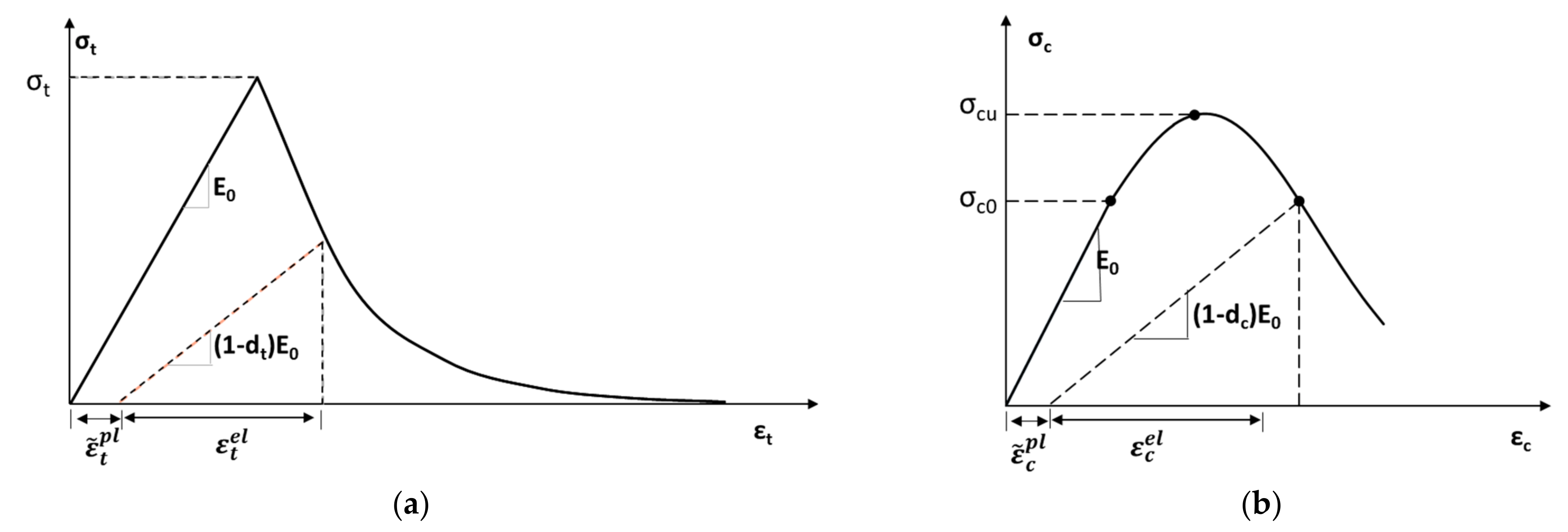
Numerical modelling of masonry is a complex task since it is very dependent on the properties of its constituent materials and the corresponding interfaces. In this study, ABAQUS software was used to model the masonry. The experimental tests of this study were reproduced using the ABAQUS Concrete Damage Plasticity (CDP) constitutive model, as suggested by many authors [29,30]. CDP is a continuum model, based on plasticity, initially addressing the damage in concrete, that has proven to be quite applicable to masonry. Basically, CDP relies on two failure mechanisms: the compressive crushing and tensile cracking of the material. According to this model the failure surface is controlled by the tensile and compressive equivalent plastic strains and , respectively [31]. In tension, the stress-strain relationship follows a linear elastic trend until it reaches the failure stress , followed afterwards by a softening stress-strain response (Figure 18a). In compression, the stress-strain behavior is linear until the initial yield stress , after which it enters the plastic regime and maintains stress hardening up to the ultimate stress . Beyond this point stress softening occurs, following a parabolic shape (Figure 18b). The material degradation in tension and in compression is introduced using the damage parameters and , respectively. This damage parameter takes values from 0 to 1, where 0 corresponds to the undamaged state, and 1 represents the complete degradation of the material.

Figure 18.
Constitutive relationship: (a) tension, (b) compression [31].
A modelling approach considering the masonry material as a homogenous material was followed for the numerical representation of the experimental tests.
4.2. Homogeneous FE Model
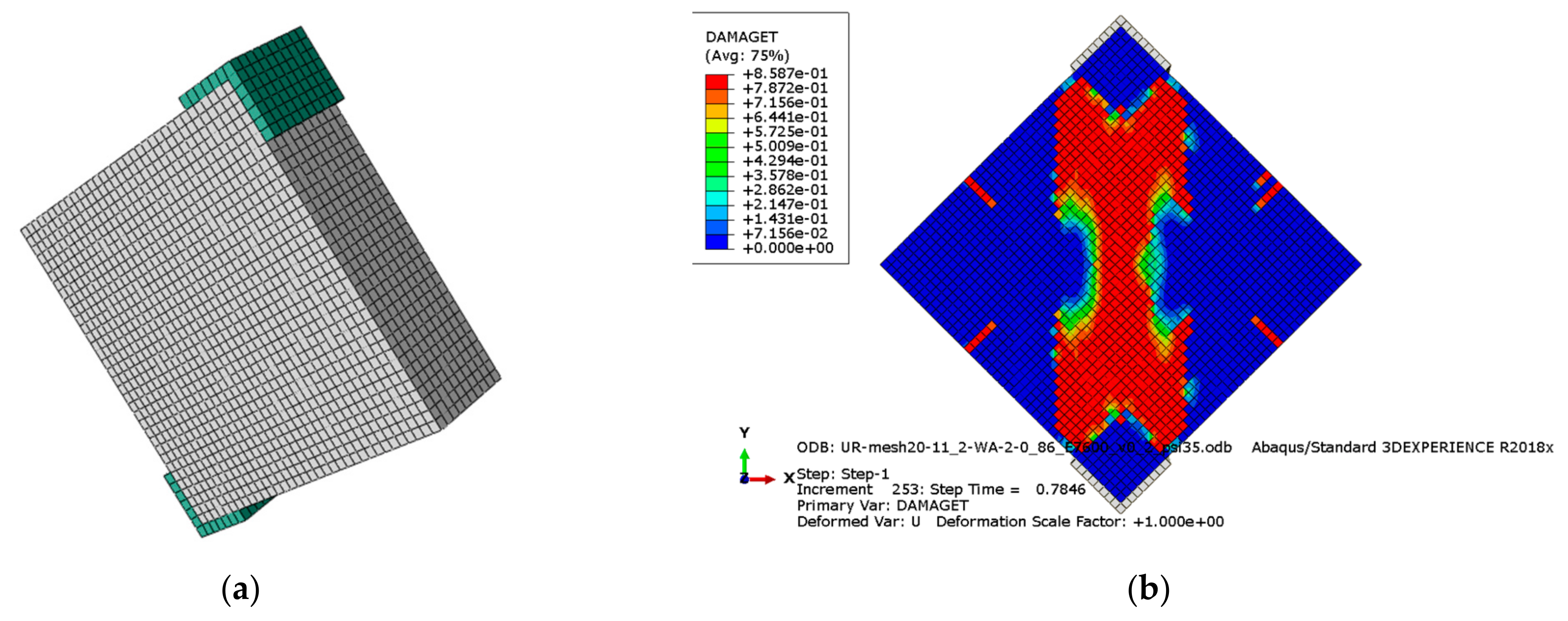
The homogeneous FE model considers the brick and mortar assemblage as a continuous homogeneous material (Figure 18). The discretization of the masonry was done using an eight-node linear hexahedral solid element with reduced integration (C3D8R). The mesh was refined to 20 mm in order to provide more accurate results (Figure 19). The inelastic compressive and tension stress-strain behavior is introduced based on the experimental test performed on the wallettes. The reinforcement bars are modelled as a two-node linear 3-D truss element (T3D2), with the mechanical properties obtained from tensile strength tests (Table 4), embedded in the masonry host material.

Figure 19.
Homogeneous FE model of unreinforced wallette. (a) meshing; (b) tension damage (Abaqus output. Note then “e-01” corresponds to “×10−1”; “e-02” corresponds to “×10−2”).
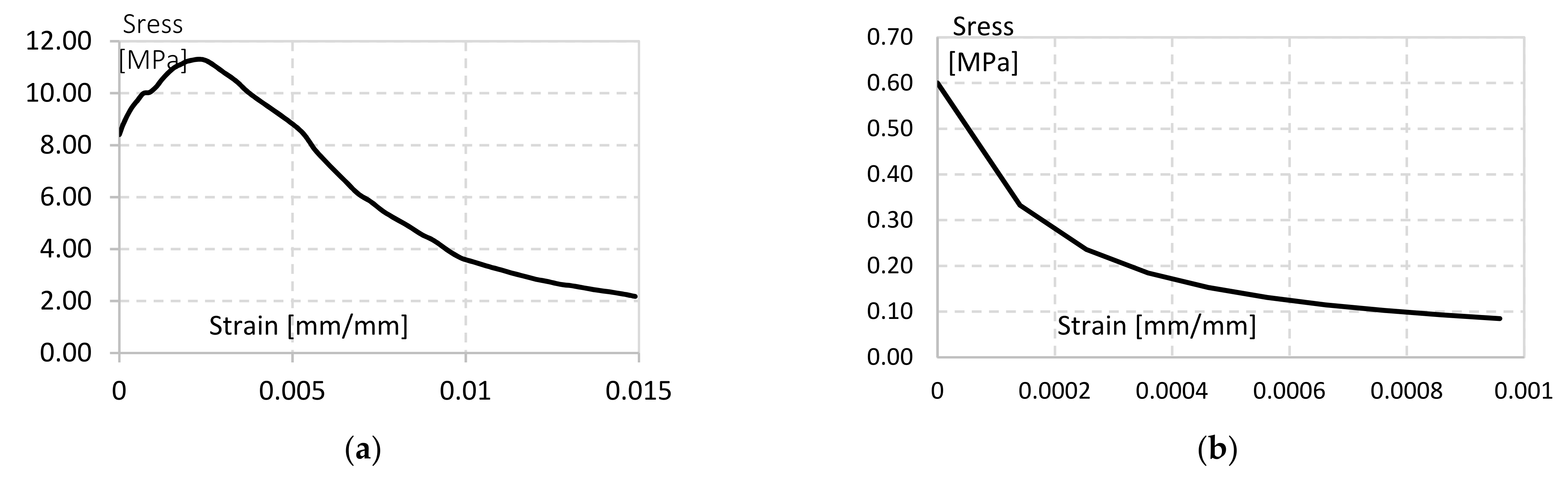
Experimental test results were used for the calibration and verification of the equivalent material properties implemented in the numerical model. Figure 20 shows the adapted inelastic stress-strain curves for the compression and tension of the homogeneous masonry material.

Figure 20.
Inelastic stress-strain behavior for homogeneous FE model: (a) compression, (b) tension.
4.3. Results of Numerical Modelling
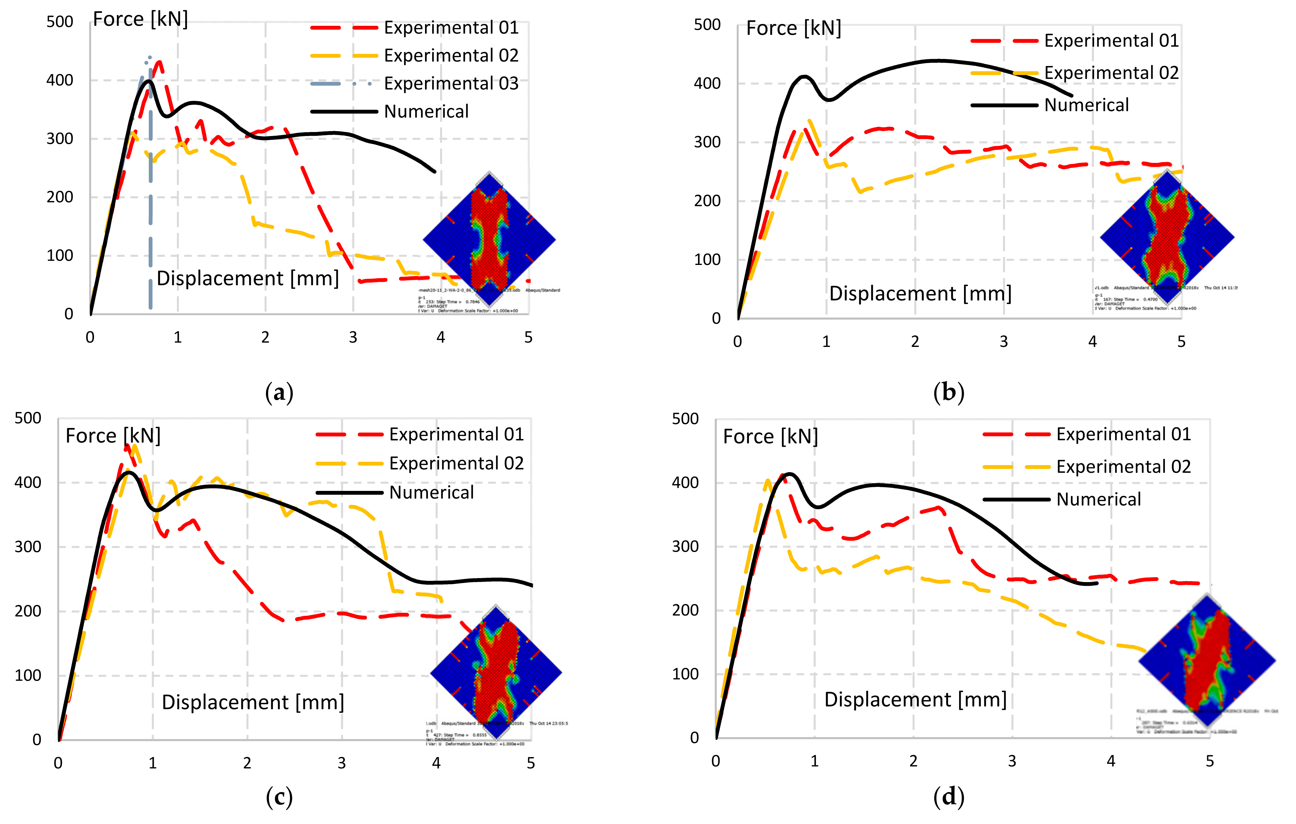
The homogeneous FE modelling approach was used for reproducing the experimental tests on unreinforced and reinforced specimens. The diagonal compression test was simulated for each reinforcement layout, and force-displacement curves have been derived for each type of reinforcement (Figure 21).
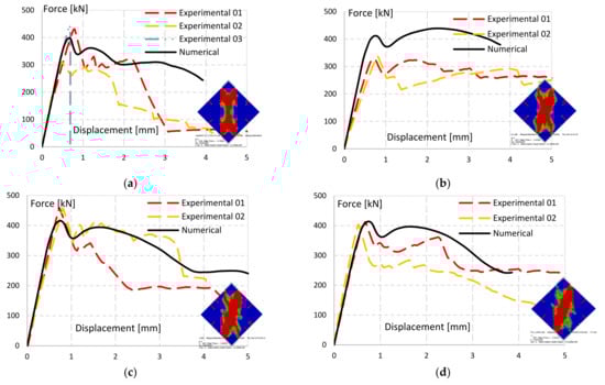
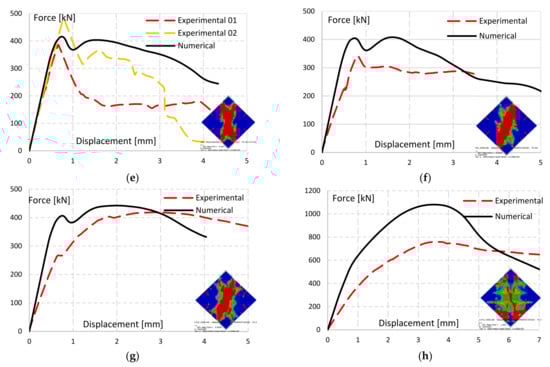
Figure 21.
Force-displacement curves of numerical models vs. experimental results. (a) UR; (b) 2HV1; (c) 1H2; (d) 2H1; (e) 1V1; (f) 2H1-SB Φ12; (g) 2HV1-SB Φ12; (h) 2DD1-SB Φ12.
The FE model of UR wallettes exhibits similar linear behavior, peak force, and post-peak degradation trend (Figure 21a). Also, the damaging pattern in the model (Figure 19b) is consistent with the damaging observed in the tests.
The FE models of the reinforced walls show damage patterns (thumbnails in Figure 21) in line with the damage obtained in the experiments, i.e., diagonal cracking and compression of the central (vertical) strut. Considering the high complexity of the wallettes’ behavior, the force-displacement-curves, although not in perfect match, satisfactorily reproduce the curves obtained in the experimental tests.
The models of TSF reinforced wallettes with horizontal-only reinforcement layout (1H2 and 2H1), with one bar at each side or with two bars on one side, present similar results in terms of linear behavior, peak force, and post-peak degradation trend when compared with experimental results. The behavior of the wallette with vertical-only reinforcement layout (1V1), is also relatively well reproduced.
The model of the TSF grid reinforcement layout, 2HV1, however, shows a steeper linear behavior and a higher peak force when compared with experimental results. This is attributed to the more severe weakening effect on the wallette caused by opening horizontal and vertical slots, which is not being considered in the numerical model. This effect, however, is recognized when the 2HV1 experimental results are compared to those of the UR wallette.
In the case of SB Φ12 reinforced specimens this phenomenon is observed also in the horizontal-only reinforcement layout, 2H1 SB Φ12, which similarly exhibited lower values during the diagonal compression test. In this case, a slighter difference is observed since the horizontal slots are less damaging than vertical plus horizontal slots.
Specimen 2HV1-SB Φ12 model also exhibits a steeper linear behavior, yet with similar ultimate load and post-peak degradation trend.
The ortho-diagonal reinforcement layout FE model, 2DD1-SB Φ12, exhibits higher peak, since the experimental test reached failure due to the crushing of the bottom vertex. This behavior was not noted in the numerical models where the improvement effect of the rebars has been overestimated.
5. Conclusions
Shear performance, a characteristic directly related to seismic performance, was evaluated in masonry walls of old masonry-concrete buildings strengthened with near surface mounted (NSM) twisted steel bars (TSB) or traditional concrete reinforcing steel bars (SB).
The walls studied have a particularity in relation to other types of old masonry walls, namely the high resistance and stiffness of bed and head joints, which is a result of the mortar composition used in a certain period, around the 1950s. These walls have been studied little, and the application of strengthening solutions developed for other types of (weaker) walls may not lead to the expected results. It is important to know the effects and performance of the traditional strengthening solutions when applied to these walls built with cement mortars.
Several layouts were considered for the reinforcement of the walls, both for the TSB and the SB solutions. These solutions were applied in the wallettes that were tested in simple compression and in diagonal compression (shear). The tests were also simulated through numerical models, which provided a quite acceptable reproduction of the experimental results.
The results with the 6 mm TSB reinforcement were relatively disappointing in terms of strength, although a slight increase in the ductility of the wallettes was noticed. In all the solutions studied—reinforcement in one direction only (horizontal or vertical) and horizontal and vertical grid reinforcement—the bars have little or no influence before the masonry cracking, which is attributed to the high stiffness of the masonry when compared to that of the steel reinforcement. On the other hand, it is important to note that, due to the high strength of the masonry, no damage is visible on the prototype before the initiation of the central diagonal crack. After this damage initiation, the bars work only in shear and local bending, instead of being solicited in pure tension, the best mode in terms of stiffness and strength of the steel bars. The masonry strength and the central diagonal crack prevent the internal decomposition of the diagonal tensile force into two orthogonal components that would be absorbed (in pure tension) by the grid reinforcing bars. Therefore, bars break locally in these areas, mainly by shear effect. However, from the occurrence of the first diagonal crack up to the specimen collapse, the presence of the reinforcement bars provided some increase in the specimens’ ductility.
Such behavior and limited effectiveness of the reinforcements was also detected in the wallettes reinforced with conventional reinforced concrete bars with larger diameter (12 mm). This increase in the bars diameter also had no significant effects on the specimens’ strength, since this increase only impacted the shear strength of the bars and did not change the damaging and collapse mode.
Finally, it should be noted that although reinforcement solutions with reinforcement placed in only one direction (horizontal or vertical) show little efficiency in terms of resistance and energy dissipation, solutions with horizontal and vertical grid reinforcement show significantly higher levels of energy dissipation than unreinforced prototypes.
It is worth noting that in masonry with weaker and softer mortars, it is expected that this reinforcement solution will provide a greater improvement, because (1) the damage in the masonry will occur in phases prior to the central damage and in a more distributed way, demanding for an earlier participation of the reinforcement; and (2) with a lower original strength and stiffness of the masonry, the participation of the reinforcement will be relatively more relevant.
In the prototype reinforced with a grid oriented at 45°, the effects are quite relevant, with a substantial increase in strength, ductility, and energy dissipation. In this case, the grid is positioned in the direction of the tensile stresses and the bars will behave in pure tension, this being the most effective. This solution, which is not very practical, may be considered if strong masonry walls have to actually be strengthened.
It can be concluded that the solutions studied may be applied in weaker lime mortar masonry walls, but that they do not have the desired effectiveness in strengthening more resistant and stiffer cement mortar masonry walls, which require further studies to find more appropriate solutions. The solutions studied may be considered in cement mortar masonry walls when only an improvement in ductility but not in strength is envisaged. In any case, the solutions with reinforcement in only one direction do not seem to present great efficiency, and it is thus preferable to use reinforcement with bars in two orthogonal directions.
Author Contributions
Conceptualization, J.G.F., A.S.G. and A.I.M.; methodology, J.G.F., A.S.G. and A.I.M.; software A.D.; validation, J.G.F., A.S.G. and A.I.M.; formal analysis, A.D.; investigation, J.G.F., A.S.G., A.I.M. and A.D.; resources, J.G.F. and A.I.M.; data curation, A.D.; writing—original draft preparation, A.D.; writing—review and editing, J.G.F., A.S.G., A.I.M. and A.D.; visualization, A.D.; supervision, J.G.F., A.S.G. and A.I.M.; project administration, J.G.F. and A.I.M.; funding acquisition, J.G.F. All authors have read and agreed to the published version of the manuscript.
Funding
This research was funded by FCT—Fundação para a Ciência e a Tecnologia through the project RESIST-2020—“Seismic Rehabilitation of Old Masonry-Concrete Buildings” ref. PTDC/ECI-EGC/30567/2017; and by Helifix UK, by proving all reinforcement materials and technical assistance.
Institutional Review Board Statement
Not applicable.
Informed Consent Statement
Not applicable.
Data Availability Statement
The data presented in this paper is available in data bases at IST servers, with no public access.
Acknowledgments
The authors gratefully acknowledge the financial support of the FCT—Fundação para a Ciência e a Tecnologia for the project RESIST-2020—“Seismic Rehabilitation of Old Masonry-Concrete Buildings” ref. PTDC/ECI-EGC/30567/2017. The support of Helifix UK, by proving all reinforcement materials and technical assistance, is gratefully acknowledged. The experimental tests were carried out at LNEC—Laboratório Nacional de Engenharia Civil, Lisbon, Portugal.
Conflicts of Interest
The authors declare no conflict of interest.
References
- Mustafaraj, E.; Luga, E.; Corradi, M.; Borri, A.; Muceku, Y.; Zharkalli, A. Physical-Mechanical Properties of Stone Masonry of Gjirokastër, Albania. Materials 2021, 14, 1127. [Google Scholar] [CrossRef] [PubMed]
- Vlachakis, G.; Vlachaki, E.; Lourenço, P.B. Learning from failure: Damage and failure of masonry structures, after the 2017 Lesvos earthquake (Greece). Eng. Fail. Anal. 2020, 117, 104803. [Google Scholar] [CrossRef]
- Stepinac, M.; Lourenço, P.B.; Atalić, J.; Kišiček, T.; Uroš, M.; Baniček, M.; Novak, M.Š. Damage classification of residential buildings in historical downtown after the ML5.5 earthquake in Zagreb, Croatia in 2020. Int. J. Disaster Risk Reduct. 2021, 56, 102140. [Google Scholar] [CrossRef]
- CEN. Eurocode 6—Design of Masonry Structures—Part 1-1 (EN 1996-1-1): General Rules for Reinforced and Unreinforced Masonry Structures; CEN: Brussels, Belgium, 2005. [Google Scholar]
- CEN. Eurocode 8 (EN 1998-1): DESIGN of Structures for Earthquake Resistance; CEN: Brussels, Belgium, 2005. [Google Scholar]
- Sousa, M.; Oliveira, C.; Costa, A. Characterization of the building stock in Mainland Portugal to study seismic risk (Original title: Caracterização do parque habitacional de Portugal Continental para estudos de risco sísmico). Rev. Port. Eng. Estrut. (RPEE) 2006, 55, 35–50. [Google Scholar]
- Ferrito, T.; Milosevic, J.; Bento, R. Seismic vulnerability assessment of a mixed masonry–RC building aggregate by linear and nonlinear analyses. Bull. Earthq. Eng. 2016, 14, 2299–2327. [Google Scholar] [CrossRef]
- Marques, A.I.; Veiga, M.d.R.; Candeias, P.X.; Ferreira, J.P. The emergence of the typology of “Placa” buildings in Lisbon (Original title: O surgimento da Tipologia dos Edifícios “De Placa” em Lisboa). In Proceedings of the 2° Congresso Internacional de História da Construção Luso-Brasileira, Porto, Portugal, 14–16 September 2016; pp. 413–424. [Google Scholar]
- Marques, A.I. Rehabilitation of Old Buildings: Reducing Seismic Vulnerability by Strengthening the Walls; Original Title: Reabilitação de Edifícios Antigos: Redução da Vulnerabilidade Sísmica Através do Reforço de Paredes. Ph.D. Thesis, Instituto Superior Técnico—Universidade de Lisboa, Lisbon, Portugal, 2020. [Google Scholar]
- Del Zoppo, M.; Di Ludovico, M.; Balsamo, A.; Prota, A. Experimental In-Plane Shear Capacity of Clay Brick Masonry Panels Strengthened with FRCM and FRM Composites. J. Compos. Constr. 2019, 23, 04019038. [Google Scholar] [CrossRef]
- Lin, Y.-W.; Wotherspoon, L.; Scott, A.; Ingham, J.M. In-plane strengthening of clay brick unreinforced masonry wallettes using ECC shotcrete. Eng. Struct. 2014, 66, 57–65. [Google Scholar] [CrossRef]
- Mustafaraj, E.; Yardim, Y. In-plane Shear Strengthening of Unreinforced Masonry Walls Using GFRP Jacketing. Period. Polytech. Civ. Eng. 2018, 62, 330–336. [Google Scholar] [CrossRef] [Green Version]
- Ismail, N.; Petersen, R.B.; Masia, M.J.; Ingham, J.M. Diagonal shear behaviour of unreinforced masonry wallettes strengthened using twisted steel bars. Constr. Build. Mater. 2011, 25, 4386–4393. [Google Scholar] [CrossRef]
- Borri, A.; Castori, G.; Corradi, M. Shear behavior of masonry panels strengthened by high strength steel cords. Constr. Build. Mater. 2011, 25, 494–503. [Google Scholar] [CrossRef]
- Gattesco, N.; Boem, I.; Dudine, A. Diagonal compression tests on masonry walls strengthened with a GFRP mesh reinforced mortar coating. Bull. Earthq. Eng. 2014, 13, 1703–1726. [Google Scholar] [CrossRef]
- Borri, A.; Castori, G.; Corradi, M. Determination of Shear Strength of Masonry Panels Through Different Tests. Int. J. Arch. Herit. 2015, 9, 913–927. [Google Scholar] [CrossRef]
- Del Zoppo, M.; Di Ludovico, M.; Balsamo, A.; Prota, A. Diagonal compression testing of masonry panels with irregular texture strengthened with inorganic composites. Mater. Struct. 2020, 53, 1–17. [Google Scholar] [CrossRef]
- Milosevic, J.; Gago, A.S.; Lopes, M.; Bento, R. Experimental assessment of shear strength parameters on rubble stone masonry specimens. Constr. Build. Mater. 2013, 47, 1372–1380. [Google Scholar] [CrossRef]
- Segura, J.; Pelà, L.; Saloustros, S.; Roca, P. Experimental and numerical insights on the diagonal compression test for the shear characterisation of masonry. Constr. Build. Mater. 2021, 287, 122964. [Google Scholar] [CrossRef]
- Corradi, M.; Borri, A.; Vignoli, A. Strengthening techniques tested on masonry structures struck by the Umbria–Marche earthquake of 1997–1998. Constr. Build. Mater. 2002, 16, 229–239. [Google Scholar] [CrossRef]
- Corradi, M.; Tedeschi, C.; Binda, L.; Borri, A. Experimental evaluation of shear and compression strength of masonry wall before and after reinforcement: Deep repointing. Constr. Build. Mater. 2008, 22, 463–472. [Google Scholar] [CrossRef] [Green Version]
- Brignola, A.; Frumento, S.; Lagomarsino, S.; Podestà, S. Identification of Shear Parameters of Masonry Panels Through the In-Situ Diagonal Compression Test. Int. J. Arch. Herit. 2008, 3, 52–73. [Google Scholar] [CrossRef]
- Borri, A.; Castori, G.; Corradi, M.; Speranzini, E. Shear behavior of unreinforced and reinforced masonry panels subjected to in situ diagonal compression tests. Constr. Build. Mater. 2011, 25, 4403–4414. [Google Scholar] [CrossRef]
- AFML. Arquivo Municipal de Lisboa. Núcleo Fotográfico, Rua da Palma. Lisboa, Portugal. Available online: http://arquivomunicipal.cm-lisboa.pt (accessed on 3 May 2021).
- European Standard EN, C. 772-1; Methods of Test for Masonry Units—Part 1: Determination of Compressive Strength. European Committee for Standardization (CEN): Brussels, Belgium, 2011.
- European Standard EN, C. 1015-11; Methods of Test Mortar for Masonry—Part 11: Determination of Flexural and Compressive Strength of Hardened Mortar. European Committee for Standardization (CEN): Brussels, Belgium, 1999.
- European Standard EN, C. 1052-1; Methods of Test for Masonry: Determination of Compressive Strength. European Committee for Standardization (CEN): Brussels, Belgium, 1999.
- ASTM E519; Standard Test Method for Diaogonal Tension (Shear) in Masonry Assemblages. American Society for Testing and Materials (ASTM): West Conshohocken, PA, USA, 2020.
- Hernoune, H.; Benabed, B.; Kanellopoulos, A.; Al-Zuhairi, A.H.; Guettala, A. Experimental and Numerical Study of Behaviour of Reinforced Masonry Walls with NSM CFRP Strips Subjected to Combined Loads. Buildings 2020, 10, 103. [Google Scholar] [CrossRef]
- Scacco, J.; Ghiassi, B.; Milani, G.; Lourenço, P.B. A fast modeling approach for numerical analysis of unreinforced and FRCM reinforced masonry walls under out-of-plane loading. Compos. Part B Eng. 2020, 180, 107553. [Google Scholar] [CrossRef]
- Documentation, A. Abaqus Online Documentation; Dassault Systemes Simulia Corporation: Providence, RI, USA, 2016. [Google Scholar]


Publisher’s Note: MDPI stays neutral with regard to jurisdictional claims in published maps and institutional affiliations. |
© 2022 by the authors. Licensee MDPI, Basel, Switzerland. This article is an open access article distributed under the terms and conditions of the Creative Commons Attribution (CC BY) license (https://creativecommons.org/licenses/by/4.0/).