
Using a Unique Retaining Method for Building Foundation Excavation: A Case Study on Sustainable Construction Methods and Circular Economy


Abstract
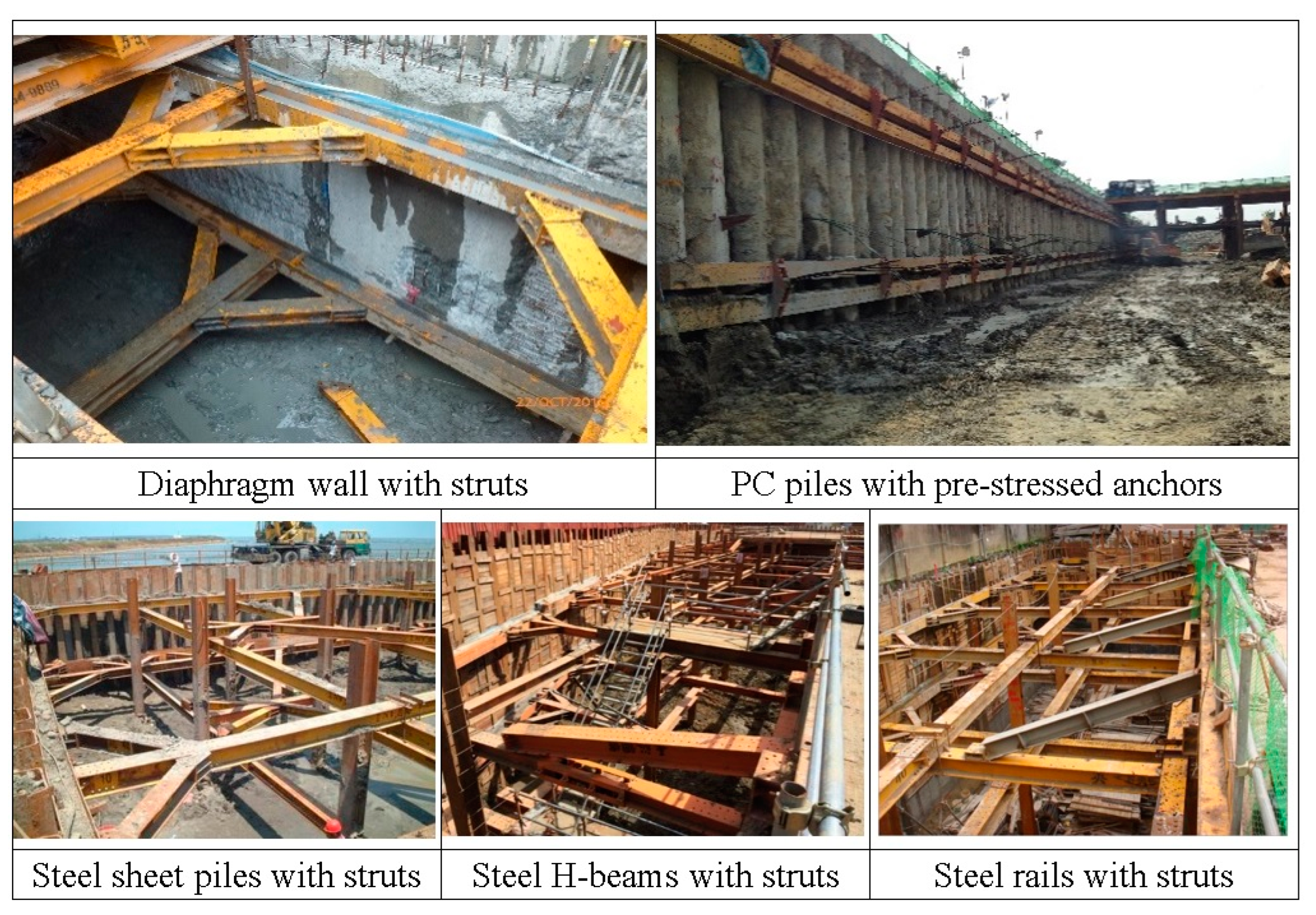
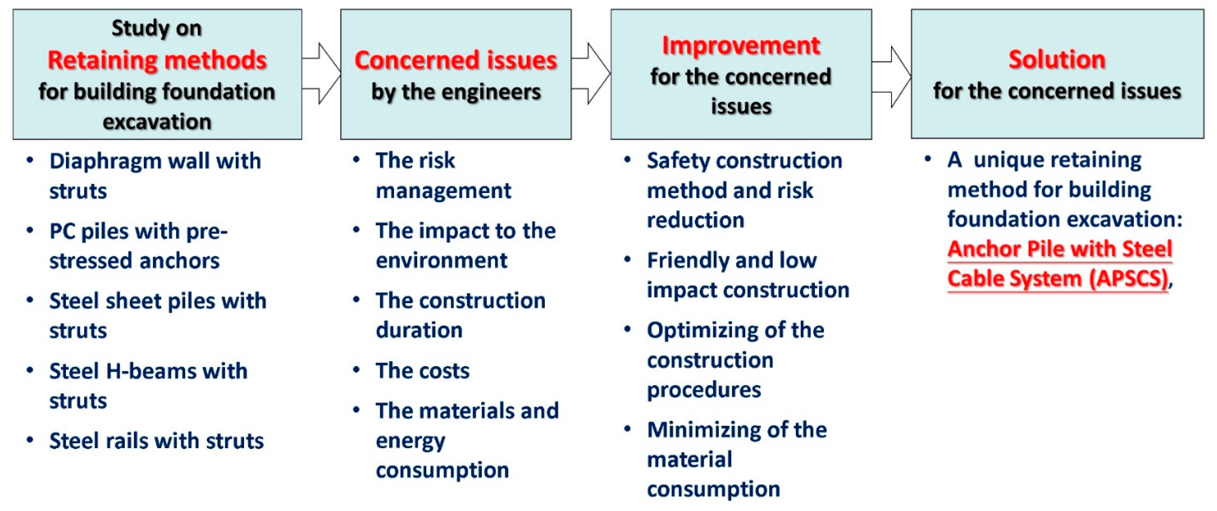
:1. Introduction
2. Case Studies on the Similar Projects
2.1. Case 1: A7 Public Housing Building—Part C (A7PHB-C)
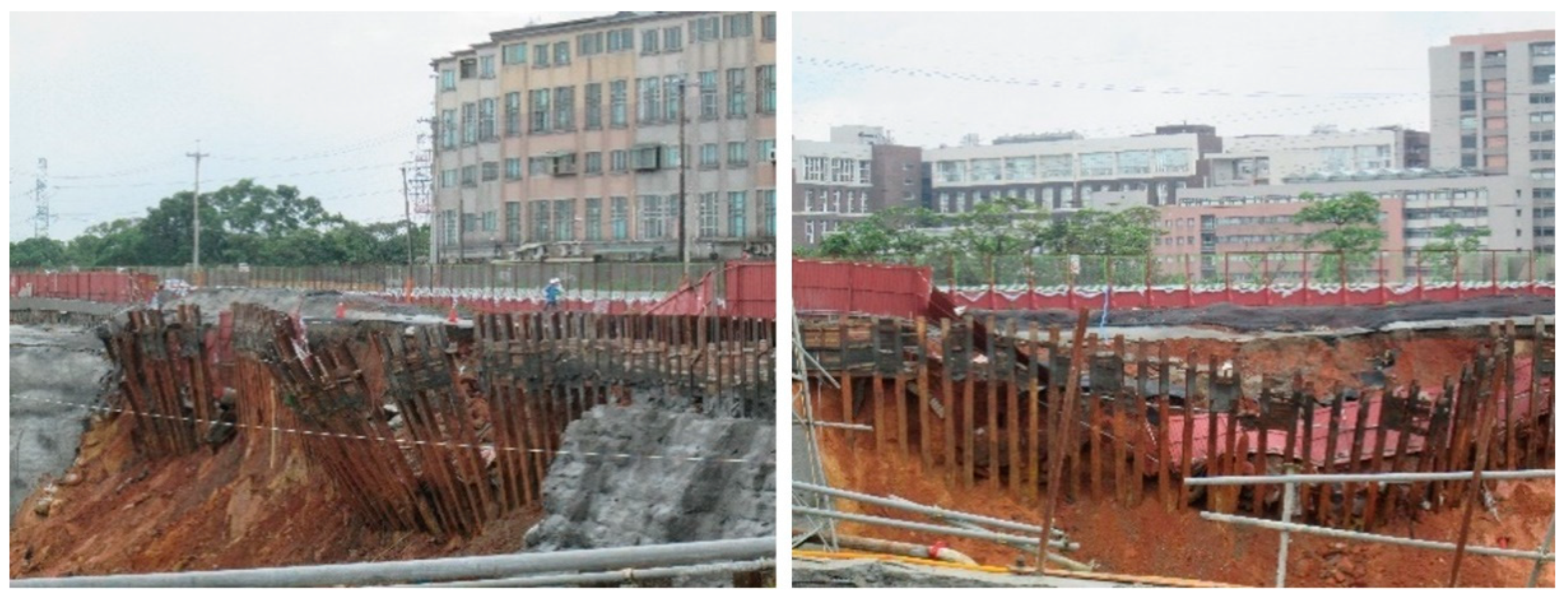
2.2. Case 2: A7 Public Housing Building—Part D (A7PHB-D)
3. Comparison of A7PHB-C and A7PHB-D
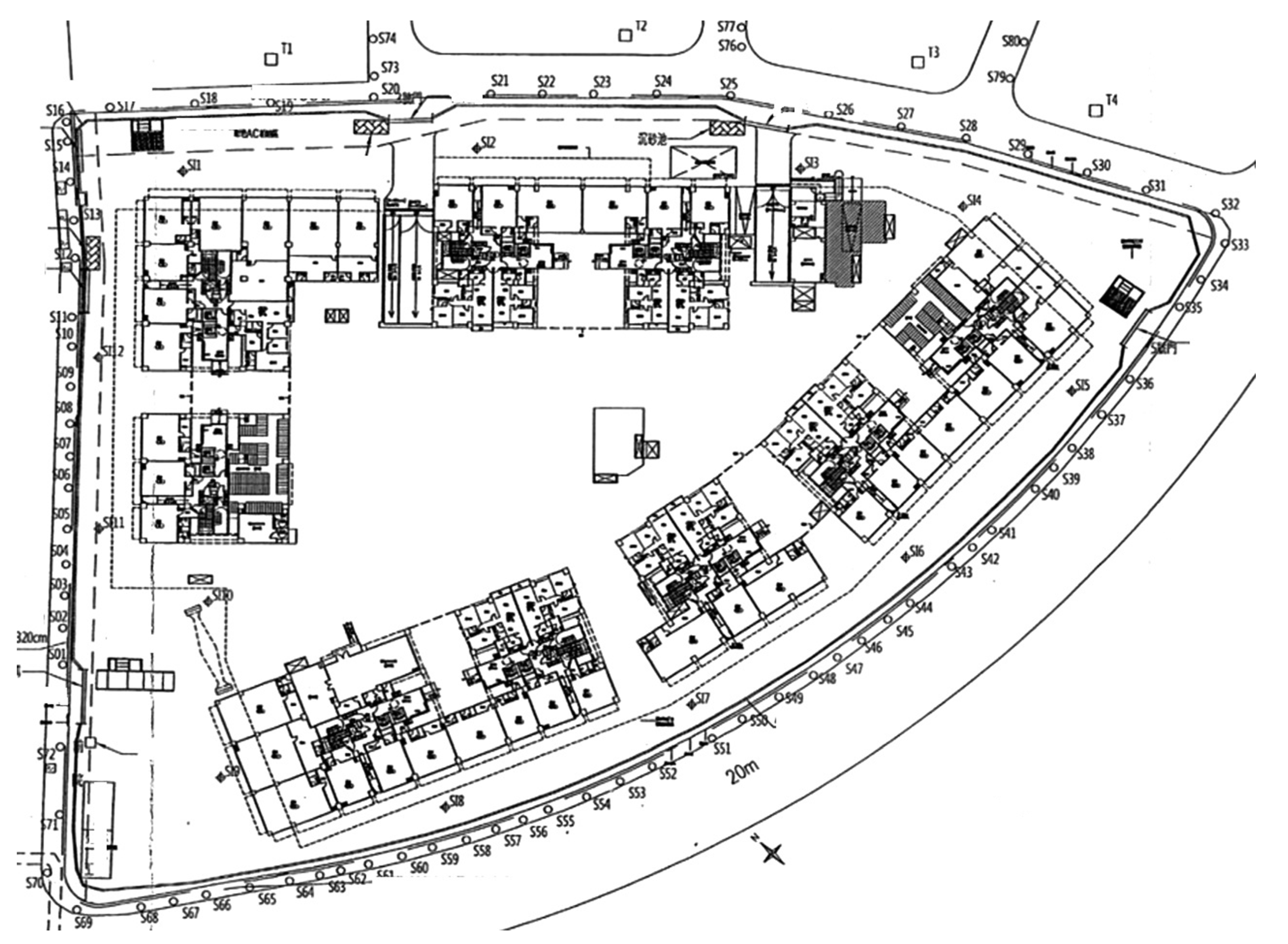
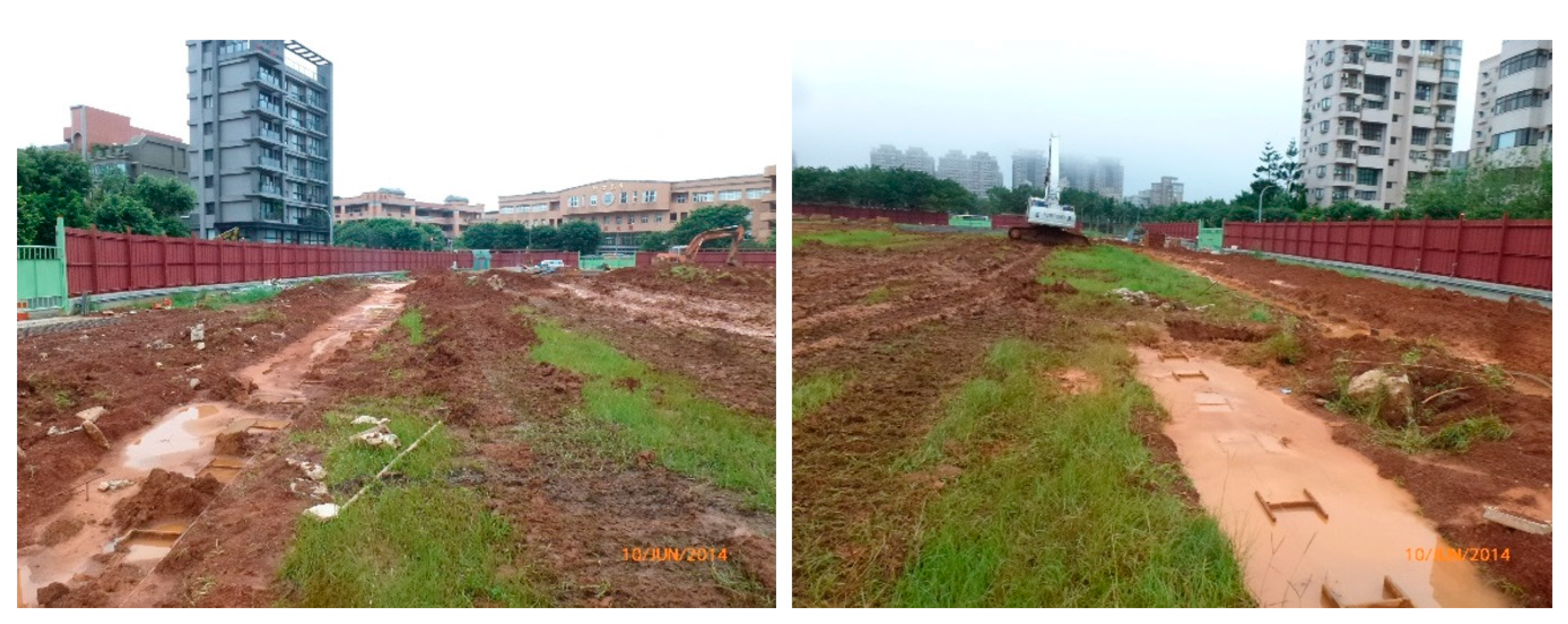
4. Description of the Linkou Public Housing Project (LPHP)
5. Special Retaining Method for Excavation Work, APSCS
5.1. Detailed Description of the Anchor Pile with Steel Cable System (APSCS)
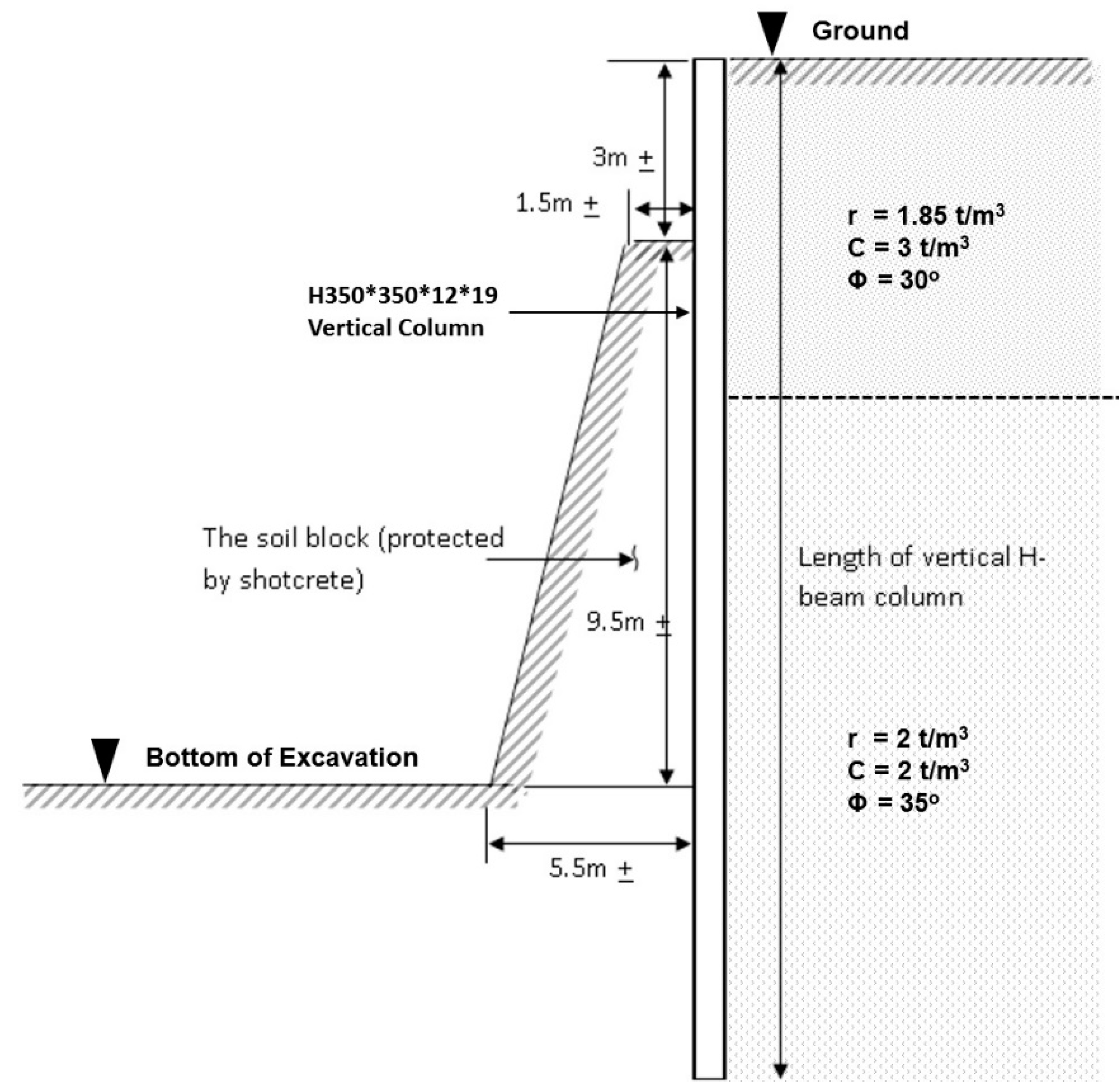
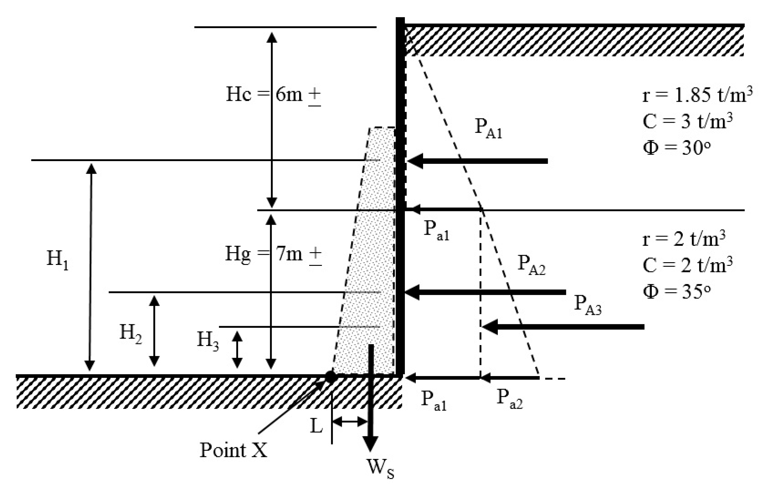
5.2. Analysis by Static Calculation
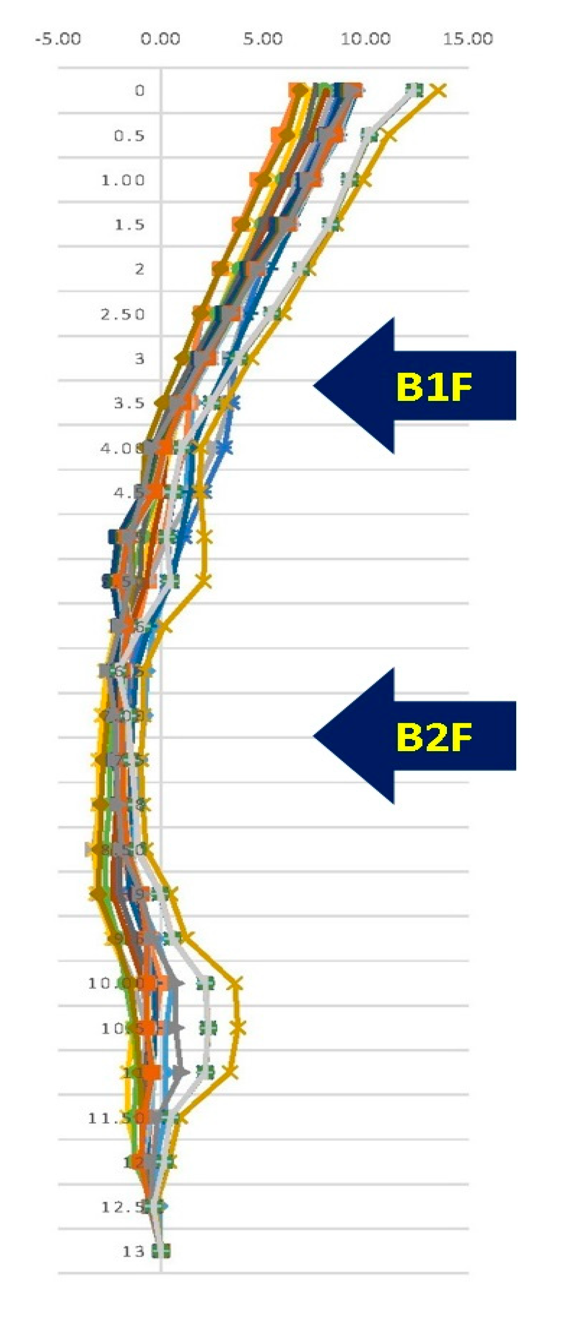
5.3. Equipped Monitoring Results during and after the Excavation
5.4. Carbon Emission Reduction for Sustainability and the Circular Economy Issue
6. Conclusions
Author Contributions
Funding
Institutional Review Board Statement
Informed Consent Statement
Data Availability Statement
Acknowledgments
Conflicts of Interest
References
- Lim, A.; Ou, C.-Y.; Hsieh, P.-G. Investigation of the integrated retaining system to limit deformations induced by deep excavation. Acta Geotech. 2018, 13, 973–995. [Google Scholar] [CrossRef]
- Lim, A.; Ou, C.-Y.; Hsieh, P.-G. A novel strut-free retaining wall system for deep excavation in soft clay: Numerical study. Acta Geotech. 2020, 15, 1557–1576. [Google Scholar] [CrossRef]
- Xu, C.; Chen, Q.; Wang, Y.; Hu, W.; Fang, T. Dynamic Deformation Control of Retaining Structures of a Deep Excavation. J. Perform. Constr. Facil. 2016, 30, 04015071. [Google Scholar] [CrossRef]
- Ye, S.; Zhao, Z.; Wang, D. Deformation analysis and safety assessment of existing metro tunnels affected by excavation of a foundation pit. Undergr. Space 2020, 6, 421–431. [Google Scholar] [CrossRef]
- Liu, J.; Song, J.; Zhang, Z.; Hu, N. Influence of the Ground Displacement and Deformation of Soil around a Tunnel Caused by Shield Backfilled Grouting during Construction. J. Perform. Constr. Facil. 2016, 31, 04016117. [Google Scholar] [CrossRef]
- Commend, S.; Geiser, F.; Crisinel, J. Numerical simulation of earthworks and retaining system for a large excavation. Adv. Eng. Softw. 2004, 35, 669–678. [Google Scholar] [CrossRef]
- Alipour, A.; Eslami, A. Design adaptations in a large and deep urban excavation: Case study. J. Rock Mech. Geotech. Eng. 2019, 11, 389–399. [Google Scholar] [CrossRef]
- Liu, T.Y. Establishment of Sustainability Key Indicators for Civil Engineering and Their Applications in Green Infrastructure Projects. Ph.D. Dissertation, Department of Civil Engineering, College of Engineering, National Taiwan University, Taipei, Taiwan, 2020. [Google Scholar] [CrossRef]
- Liu, T.-Y.; Chen, P.-H.; Chou, N.N.S. Comparison of Assessment Systems for Green Building and Green Civil Infrastructure. Sustainability 2019, 11, 2117. [Google Scholar] [CrossRef] [Green Version]
- Shen, L.; Wu, Y.; Zhang, X. Key Assessment Indicators for the Sustainability of Infrastructure Projects. J. Constr. Eng. Manag. 2011, 137, 441–451. [Google Scholar] [CrossRef] [Green Version]
- Lin, S.J.; Liu, T.Y.; Chou, N.N.; Chen, P.H.; Liao, C.L. Soil Improvement and In-spection Techniques for the Base Course of Rigid Pavement for an Airport Runway. ASCE J. Perform. Constr. Facil. 2020, 35, 06021001. [Google Scholar] [CrossRef]
- Shau, H.-J.; Liu, T.-Y.; Chen, P.-H.; Chou, N.N.S. Sustainability Practices for the Suhua Highway Improvement Project in Taiwan. Int. J. Civ. Eng. 2019, 17, 1631–1641. [Google Scholar] [CrossRef]
- Yates, J.K. Design and Construction for Sustainable Industrial Construction. J. Constr. Eng. Manag. 2014, 140, B4014005. [Google Scholar] [CrossRef]
- Chisholm, D.; Reddy, K.; Beiler, M.R.O. Sustainable Project Rating Systems, Including Envision. In Engineering for Sustainable Communities: Principles and Practices; ASCE: Reston, VA, USA, 2017; Chapter 20. [Google Scholar] [CrossRef]
- PAS 2050; Specification for the Assessment of the Life Cycle Greenhouse Gas Emissions of Goods and Services. British Standards Institution (BSI): London, UK, 2011.
- ISO/TS 14067; Specifies Principles, Requirements and Guidelines for the Quantification and Communication of the Carbon Footprint of a Product. British Standards Institution (BSI): London, UK, 2013.
- Bowles, J.E. Foundation Analysis and Design; McGraw-Hill, Inc.: New York, NY, USA, 1988. [Google Scholar]
- New Asia Construction and Development Corp. Site SPT Test Report for Taipei 2017 Summer Universiade Athlete’s Village and Linkou Public Housing Project. 2013; unpublished article. (In Chinese) [Google Scholar]
- New Asia Construction and Development Corp. Basement Excavation Plan for Taipei 2017 Summer Universiade Athlete’s Village and Linkou Public Housing Project. 2013; unpublished article. (In Chinese) [Google Scholar]
- New Asia Construction and Development Corp. Analysis and Calculation of Basement Excavation Retaining Method for Taipei 2017 Summer Universiade Athlete’s Village and Linkou Public Housing Project. 2003; unpublished article. (In Chinese) [Google Scholar]


| Excavation Items | Sum/unit | Remarks |
|---|---|---|
| Planned area of excavation | 11,739 m2 | Close to rectangular shape |
| Depth of excavation | 11.2 m | Divided into four layers of excavation |
| Total soil volume of excavation | 134,960 m3 | |
| Steel strut layers | Three layers | Struts with single and double H-shaped struts |
| Total struts weight | 2163 tons | |
| Duration of excavation work | Two months and six days | This included the lean concrete placement and strut erection |
| Basement construction duration | Five months and six days | This included the construction for the first-floor slab and the strut demolition |
| Excavation Items | Sum/Unit | Remarks |
|---|---|---|
| Depth of excavation | 12.3 m | Divided into four layers of excavation |
| Steel strut layers | No Strut | |
| Duration of excavation work | Seven months and six days | This included the lean concrete placement and reconstruction of the failed retaining steel H-shaped column |
| Basement construction duration | Six months | This included the construction for the first-floor slab |
| Parameters or Items | Equations | Value of the First Layer | Value of the Second Layer |
|---|---|---|---|
| Coefficient of at-rest earth pressure, K0 | K0 = 1 − sinØ | 0.500 | 0.426 |
| Coefficient of active earth pressure, KA | KA = tan2 (45o − Ø/2) | 0.333 | 0.271 |
| Coefficient of passive earth pressure, KP | KP = tan2 (45o + Ø/2) | 1.012 | 1.010 |
| Retaining height, Hc/Hg (m) | 6.000 | 7.000 | |
| Dry soil density, rd (t/m3) | 1.850 | 2.000 | |
| Earth pressure per unit of width due to soil pressure, Pa1 (t) | Pa = KA × H × rd | 3.700 | 3.700 |
| Earth pressure per unit of width due to soil pressure, Pa2 (t) | 3.794 | ||
| Resultant active earth pressure, PA1 (t) | PA1 = Pa1 × Hc × (1/2) | 11.100 | |
| Resultant active earth pressure, PA2 (t) | PA2 = Pa2 × Hg | 25.900 | |
| Resultant active earth pressure, PA3 (t) | PA3 = Pa3 × Hg × (1/2) | 13.279 | |
| Weight of the soil block (t) | V × rd | 70.000 | |
| Gravity center of soil block in relation to the retaining boundary O, L (m) | 3.000 | ||
| Height of pressure PA1, H1 (m) | Hc × (1/3) + Hg | 9.000 | |
| Height of pressure PA2, H2 (m) | Hg × (1/2) | 3.500 | |
| Height of pressure PA3, H3 (m) | Hg × (1/3) | 2.333 | |
| Turning moment produced by PA1, M1 (t–m) | PA1 × H1 | 99.900 | |
| Turning moment produced by PA2, M2 (t–m) | PA2 × H2 | 90.650 | |
| Turning moment produced by PA3, M3 (t–m) | PA3 × H3 | 30.983 | |
| Total turning moment, MA (t–m) | MA = M1 + M2 + M3 | 221.533 | |
| Turning moment produced by Ws, Ms (t–m) | Ms = Ws × L | 210.000 | |
| Safety factor | Ms/MA | 0.948 | |
| Items | A7PHB-C | A7PHB-D | LPHP | Remarks |
|---|---|---|---|---|
| Soil condition | Laterite–gravel soil (LGS) layer mixed with brown silty and sandy clay | Laterite–gravel soil (LGS) layer mixed with brown silty and sandy clay | Laterite–gravel soil (LGS) layer mixed with brown silty and sandy clay | The soil contents is the same for these three projects |
| Groundwater level | Under excavation bottom level | Under excavation bottom level | Under excavation bottom level | There was no groundwater in the Linkou district |
| Planned area of excavation | 11,739 m2 | 14,295 m2 | 16,060 m2 | |
| Depth of excavation | 11.2 m | 12.3 m | 10.6 m | |
| Steel strut layers | Three layers of struts | No Strut | No Strut | |
| Duration of excavation work | Two months and six days | Seven months and six days | One month and seven days | The duration of A7PHB-D includes the reconstruction of the failed retaining steel H-shaped column |
| Basement construction duration | Five months and six days | Six months | Four months and two days | |
| Retaining-system safety factor | 1.792 | 0.948 | 1.543 | |
| Materials used in the retaining system | 2163 t | 876 t | 342 t | |
| Environmental protection | High carbon emissions cause by the high material consumption | High carbon emissions caused by the collapse accident | Low carbon emissions | |
| The effectiveness of the construction method | Low effectiveness | Low effectiveness | High effectiveness |
| Excavation Items | Sum with Unit | Remarks |
|---|---|---|
| Planned area of excavation | 16,060 m2 | Close to a triangular shape |
| Depth of excavation | 10.6 m | Divided into four layers of excavation |
| Total soil volume of excavation | 185,500 m3 | |
| Steel strut layers | None strut member | |
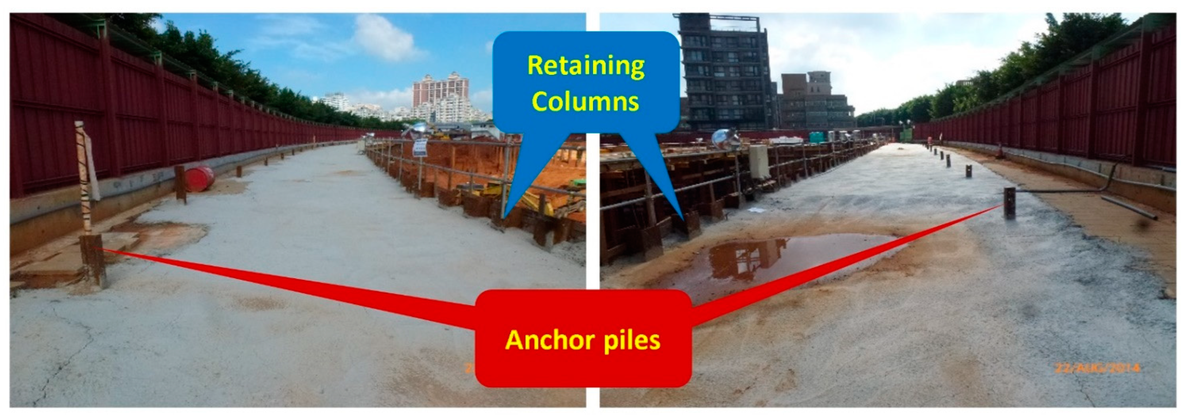
| Anchor piles for bearing forces | 97 pcs. | Steel rails of 50 kg grade, L = 13 m |
| Duration of excavation work | One month and seven days | This included the lean concrete placement |
| Basement construction duration | Four months and two days | This included the construction for the first-floor slab |
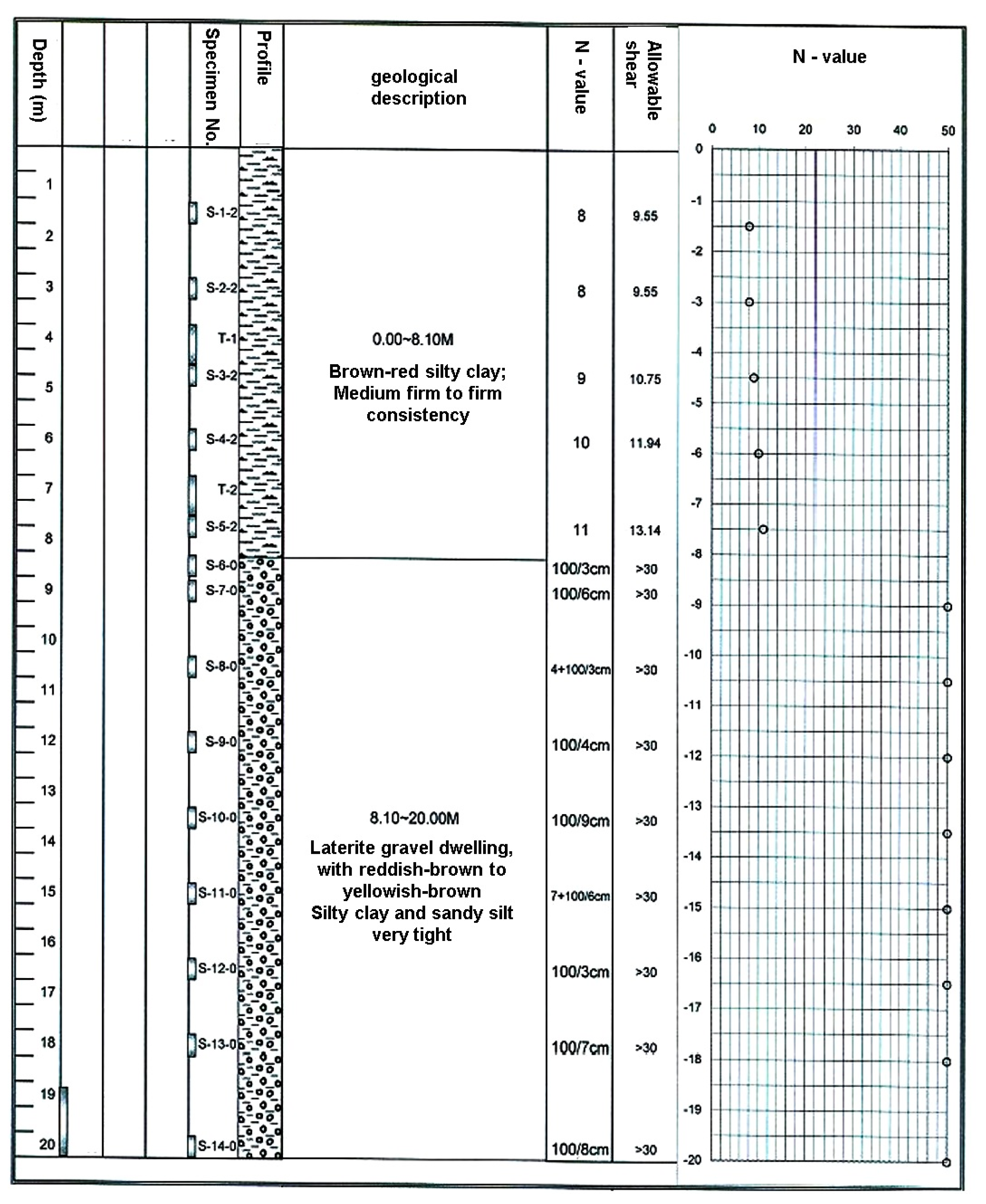
| Layer | Contents | Depth (G.L.) | N Value | Unit Weight | Cc/Cs (T/m3) | Kv (T/m3) | Kh (T/m3) | Su (T/m3) | c (T/m3) | Ø (o) | C’ (T/m3) | Ø’ (o) |
|---|---|---|---|---|---|---|---|---|---|---|---|---|
| 1 | Clay/Lateritic–gravel soil | 0~5 | 6~12 (say 8) | 1.84 | 0.2/0.02 | 1600 | 1600 | 4.2 | 2.5 | 15.0 | 0.0 | 29.0 |
| 5~9.8 | 12~24 (say 18) | 1.87 | 0.2/0.02 | 3600 | 2230 | 10.8 | 5.5 | 15.0 | 0.0 | 32.0 | ||
| 2 | Lateritic–gravel soil | 9.8~ | >50 | 2.20 | NP | 8000 | 3380 | NP | 1.0 | 35.0 | 0.0 | 42.0 |
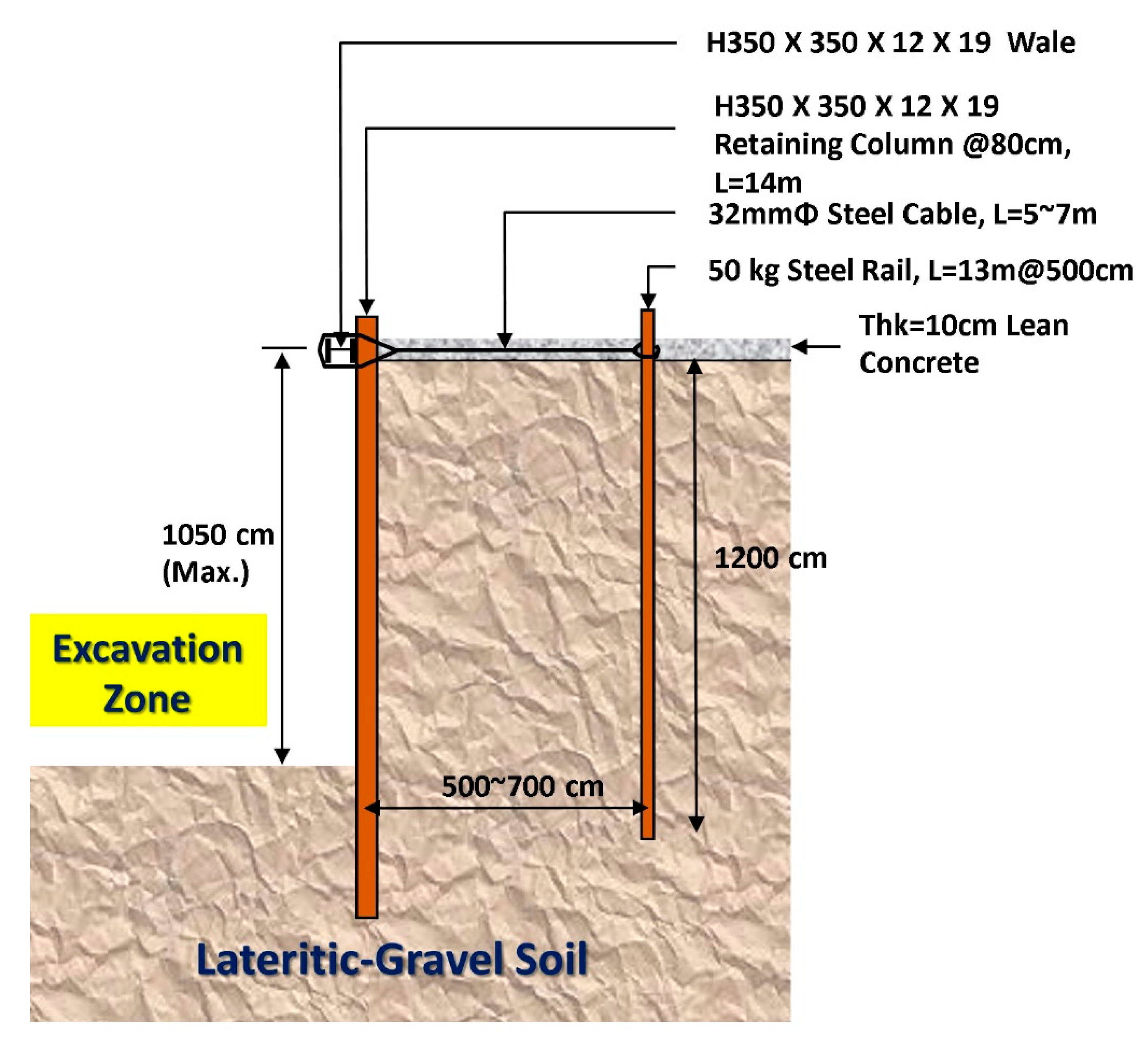
| Items | Description | Quantity | Remarks (G.L. in Reference to Ground Level) |
|---|---|---|---|
| Vertical steel column | H350 × 350 × 12 × 19, L = 16 m | @0.8~1 m | G.L. 0~−16 m |
| Horizontal wales | H350 × 350 × 12 × 19 | 1 | G.L. −0.8 m ± |
| Steel cable | D32 mmΦ, L = 5~7 m | @5~6 m | For forces transferring from the anchor pile to the wall |
| Anchor piles | 50 kg grade steel rail, L = 14 m | @5~6 m | G.L. 0.5~−13.5 m |
| Protective concrete layer | f’c = 140 kg/cm2, Thk = 20 cm, W = 5~6 m | On the ground level, around the site | With D = 6 mm wire mesh |
| Parameters or Items | Equations | Calculated Value |
|---|---|---|
| Dry soil density, rd (t/m3) | 2.0 | |
| The angle of internal friction (°) | 35.0 | |
| Surcharge | 0.0 | |
| Retaining height, H (m) | 9.6 | |
| Coefficient of at-rest earth pressure, K0 | K0 = 1 − sinØ | 0.4264 |
| Coefficient of active earth pressure, KA | KA = tan2 (45° − Ø/2) | 0.271 |
| Coefficient of passive earth pressure, KP | KA = tan2 (45° + Ø/2) | 3.69 |
| Earth pressure per unit of width due to soil pressure, Pa1 (t) | Pa1 = KA × H × rd | 5.203 |
| Earth pressure per unit of width due to soil pressure, Pa2 (t) | Pa2 = K0 × H × rd | 0.0 |
| Pa1 + Pa2 | 5.203 | |
| Resultant active earth pressure, PA (t) | PA = Pa1 × H × (1/2) + Pa2 × H | 24.974 |
| Parameters or Items | Equations | Calculated Value | Remark |
|---|---|---|---|
| Maximum lateral force, Pmax (kg) | Pmax = PA × 1000 | 24,974 | |
| H350 column length, L (cm) | L = H × 100 | 960 | |
| Height of H350, Hh (cm) | Hh = 350/10 | 35 | |
| Cross sectional area of H350, Area (cm2) | 173.87 | ||
| Second axial moment of H350 shape, Ix (cm4) | Ix = Bh × Hh3/12 | 40,295 | |
| Maximum moment in H350 column, Mmax (kg-cm) | Pmax × a × b2 × (2 × L + a)/ (2 × L3) | 2,367,905 | Please refer to Figure 13 |
| Maximum moment stress, σmax (kg/cm2) | σmax = Mmax × (Hh/2)/Ix | 1028 | |
| Maximum shear stress, τmax (kg/cm2) | τmax = Pmax/Area | 144 | |
| Maximum horizontal deflection, Δmax (cm) | Δmax = Pmax × L3/(48 × E × Ix) | 5.44 | E = 2.1 × 10⁶ |
| No | Items | Unit | Summary | Carbon Emission Factor | Carbon Reduction (kg) | Remark |
|---|---|---|---|---|---|---|
| 1 | Strut | Kg | 2,550,000 | 2.42 | 617,100 | Material ratio = 10% |
| 2 | Transportation | t-km | 99,500 | 0.24 | 23,800 | |
| 3 | Diesel fuel (fixed location) | L | 3100 | 3.42 | 10,602 | |
| 4 | Diesel fuel (moved location) | L | 4320 | 3.45 | 14,904 | |
| 5 | Gas fuel | L | 3500 | 3.10 | 10,850 | |
| 6 | Power | set | 350 | 0.69 | 242 | |
| Total | 677,578 |
Publisher’s Note: MDPI stays neutral with regard to jurisdictional claims in published maps and institutional affiliations. |
© 2022 by the authors. Licensee MDPI, Basel, Switzerland. This article is an open access article distributed under the terms and conditions of the Creative Commons Attribution (CC BY) license (https://creativecommons.org/licenses/by/4.0/).
Share and Cite
Liu, T.-Y.; Ho, S.-J.; Tserng, H.-P.; Tzou, H.-K. Using a Unique Retaining Method for Building Foundation Excavation: A Case Study on Sustainable Construction Methods and Circular Economy. Buildings 2022, 12, 298. https://doi.org/10.3390/buildings12030298
Liu T-Y, Ho S-J, Tserng H-P, Tzou H-K. Using a Unique Retaining Method for Building Foundation Excavation: A Case Study on Sustainable Construction Methods and Circular Economy. Buildings. 2022; 12(3):298. https://doi.org/10.3390/buildings12030298
Chicago/Turabian StyleLiu, Tai-Yi, Shiau-Jing Ho, Hui-Ping Tserng, and Hong-Kee Tzou. 2022. "Using a Unique Retaining Method for Building Foundation Excavation: A Case Study on Sustainable Construction Methods and Circular Economy" Buildings 12, no. 3: 298. https://doi.org/10.3390/buildings12030298
APA StyleLiu, T.-Y., Ho, S.-J., Tserng, H.-P., & Tzou, H.-K. (2022). Using a Unique Retaining Method for Building Foundation Excavation: A Case Study on Sustainable Construction Methods and Circular Economy. Buildings, 12(3), 298. https://doi.org/10.3390/buildings12030298