Abstract
To reduce the global emission of CO2 from the building industry, researchers, architects and manufacturers must consider new ways of constructing precast concrete buildings. Modern concrete columns and walls are not optimized to the applied load, and there is potential to save material. By creating a stronger column core and a lightweight concrete cover, it is possible to reduce the carbon footprint. A method is proposed to calculate such eccentrically loaded columns of two or more materials. The analytical method is developed for straight columns and columns with Entasis. Production of curved Entasis columns is possible by using textile molds due to the low mold pressure from the light aggregate concrete. Two column types are load tested to confirm the method. The CO2 emission is calculated for some column examples, and it shows that an optimized column geometry often leads to a reduced carbon footprint compared to regular columns. The concept is especially efficient for slender columns. Furthermore, the external light aggregate concrete layer ensures protection against fire if high-strength concrete is applied as the column core.
1. Introduction
Modern concrete columns are often precast to reduce cost and achieve easier assembly at the construction site. Ordinary precast columns consist of one type of concrete, they are reinforced to give a certain level of ductility, and they are straight with all cross-sections being equal.
Many attempts were made to decrease the use of the material in concrete columns. A reduction in material consumption often leads to a reduced carbon footprint and lowered costs.
Composite column solutions are becoming more popular, and the purpose is often to develop concrete confinement and, as a result, reduce the cross-section size, see Figure 1A. Mirmiran and Shahawy [1] were some of the front runners using FRP to confine reinforced concrete. They used FRP jackets as a permanent mold for reinforced concrete columns and found via several tests that this confinement gave a benefit for the load-carrying capacity compared to unconfined concrete columns. Hany et al. [2] made FEM-based investigations to verify similar FRP confined column specimens, and others have tried to reduce the carbon footprint further by utilizing reused aggregates for the confined concrete [3,4].
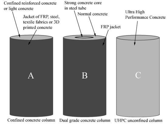
Figure 1.
Proposals from the literature to improve strength and stability of concrete columns.
Steel has been widely investigated when used to confine concrete columns, and this has been used in practice [5]. Kibriya [6] showed a 300% to 400% increase in capacity using steel tube confined concrete columns. Lacki et al. [7] investigated different cross-sections via FE-modeling, with both I-section profiles embedded in the concrete and hollow steel profiles as permanent molds for the concrete column. The approach with entirely confined concrete in hollow steel profiles seems to have been the most thoroughly investigated method [8] and used in many different applications [9]. Goncalves and Carvalho [10] created a 2D Euler–Bernoulli method based on Eurocode 4. Here, I-section steel profiles were investigated as purely encased and as a semi-mold for a hybrid column type, where the concrete and additional reinforcement were poured in the space between the flanges of the I-profile. Cakiroglu et al. [11,12] optimized the carbon footprint and price of concrete-filled steel profiles using metaheuristic algorithms.
Ozbakkalolu [13] made tests of a Double Skin Tubular Column (DSTC) where two grades of concrete were used; in the core of the column, a stronger concrete was poured, which was confined by a steel tube. A regular concrete was used outside the steel tube, which was again confined by an FRP jacket, see Figure 1B. The results showed improved structural performance and were claimed to have a lower carbon footprint.
Different types of lightweight aggregate concrete in columns have been tested both without [14] and with steel profile confinement [15,16,17,18].
Other column confinement methods have been investigated in recent years, such as textile fabrics [19] and 3D printed concrete “shells” [20]. Zhu et al. [20] seem to be the only ones to have investigated how a concrete jacket of a stronger concrete could have the potential to confine an ordinary concrete core if papers concerning in situ strengthening of existing concrete columns (e.g., [21]) are disregarded.
Another method for improving the concrete column strength and stability (which does not include concrete confinement) is ultra-high-performance concrete (UHPC), see Figure 1C. UHPC was thoroughly investigated in regards to seismic actions [22]. Li et al. [23] found that the steel fibers in their UHPC specimens gave significantly better residual capacity after a blast load was applied to tested columns.
1.1. Column Design Historically
In a historical context, columns have been used since ancient times in the Roman Empire. Over the years, several papers concern an analysis of the shapes of ancient columns with Entasis (e.g., [24,25,26,27]). Entasis is a light convex curve of the surface of a column with a circular cross-section. For instance, the column can have a larger diameter in the middle than at the bottom and top.
One possible reason for the Entasis shape could be to avoid an optical illusion that slender straight columns seem to be thinner at the middle [27]. Nevertheless, the actual reason is unknown, since a large part of the material from the famous Roman architect and engineer Vitruvius, who designed many Roman columns, is lost [24]. Thomson et al. [26] concluded that Entasis possibly is just the apparent “engineering reason”, which is to minimize the use of the material in the column to where it is required structurally. The idea of creating such optimized structural shapes has become relevant again in recent years as we discover the links between the use of building materials, CO2 emissions, and the climate and biodiversity crisis of the Earth.
1.2. Research Scope and Significance
Minimizing the use of concrete and the carbon footprint in modern precast concrete columns is challenging and closely linked to practical application and cost parameters. The paper aims to present research of a new concrete column type that in some cases reduces the emission of CO2 compared to typical precast columns while maintaining an easy production method and sufficient stability.
The new type of column utilizes Super-Light (SL) technology [28], which in this case is to create reinforced columns with strong concrete in the center and covered by a stabilizing layer of Light Aggregate Concrete (LAC). The Super-Light LAC type is used in building slabs in a number of countries with compressive strengths down to 3 MPa.
Aside from the contribution to the column stability, the LAC has the benefit of protecting the strong concrete and the reinforcement from fire [29]. Furthermore, it reduces the Global Warming Potential (GWP) [30] in many cases. Additionally, the LAC creates a much smaller pressure on the casting molds when hardening, and this enables the use of textile fabric molds to create an optimized shape inspired by the ancient column Entasis.
The state-of-the-art in the paper is a proposed SL column with a combination of strong concrete and LAC and a corresponding elastic analytical method to calculate the capacity without and with Entasis, see Figure 2.
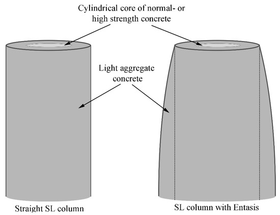
Figure 2.
SL column examples without and with Entasis.
The holistic approach of the SL column design has several benefits, which have not been investigated in the literature or seen in practice for precast columns before. A summary of the benefits is given below:
- The LAC protects the core from fire and enables the use of high-strength concrete. High-strength concrete suffers from explosive spalling if exposed to fire;
- The LAC can be cast using a flexible mold with, e.g., Entasis shape due to the low weight. The Entasis shape can reduce the volume of concrete in the column and the carbon footprint;
- The LAC stabilizes the strong concrete core, and the core can become very slender if desired.
The use of an elastic calculation method (uncracked cross-section) utilizes the stiffness of both the strong core and the LAC in resisting column deflection. It will always be safe since it is a lower bound solution. A plastic approach may provide a higher capacity in many cases and is an interesting future study, but this paper is devoted to investigating the behavior of the uncracked SL column with Entasis.
The paper does not concern connection details, and the columns are considered to be simply supported. The simply supported ends could be designed as concrete hinges, similar to many bridge pillars. Alternatively, concrete saddle bearings could be applied, with the ends of the concrete core having a spherical shape that would fit the adjacent structure.
The methods can be used for composite walls and columns of different concrete grades. The cost of production and materials was not considered in the study.
2. Composite Columns of Different Types of Concrete
The composite column type presented here does not require steel tubes or FRP jackets to achieve the required strength and stability, making the production more straightforward. The strong concrete core is stabilized and protected by the LAC, see Figure 2. Longitudinal reinforcement can be positioned in either the strong concrete or LAC.
2.1. Columns with a Constant Cross-Section
The usual Euler equation is used to calculate the capacity of a plain column in one linear elastic material loaded by a central load F:
FE is the Euler force (normal force), E0 is the beginning of Young’s modulus, I is the moment of inertia, and L is the column length. Euler used a sinusoidal deflection shape. The equation only includes the column’s stability, not the limiting factor of compressive strength, relevant for shorter columns.
Rankine, and later Ritter, evolved the theory by including the ultimate compressive load of the material, Fu, and by applying equilibrium of the column, taking into account the curved strain–stress relationship of the material (see Figure 3):
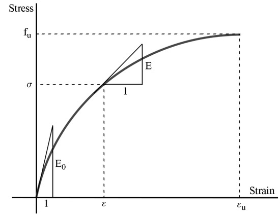
Figure 3.
Ritter strain-stress relation.
From Equation (2), we can determine the equation of Ritter’s working curve
In a deflected column, the force at equilibrium FR is called the Rankine force, which is the ultimate load of a centrally loaded column
Based on Equation (4), the following condition of the Rankine force can be found
For a very short column, the Euler load FE becomes large, 1/FE can be neglected, and the Rankine force will equal the ultimate compressive load Fu. For a very long and slender column, FE will become small and 1/FE much larger than 1/Fu, and the Rankine force will be equal to the Euler load.
Concrete columns also have reinforcement, and if the cross-section consists of different grades of concrete, that must be considered. Regular concrete, light aggregate concrete and reinforcement have the same deflection, and all the materials have a curved strain–stress relationship. Based on this, it is possible to determine a Rankine load for each constituent, assuming that each material remains in the same position in the cross-section.
Each contribution of the column cross-section can be added to determine the total Rankine load when loaded centrally. The materials must be weighted by their material stiffness.
The subscript c is for ordinary concrete, lc is LAC, and s is steel. A method similar to that also exists for calculations of concrete columns in fire [29].
In practice, columns are calculated with an eccentricity e, of the applied normal load, F. In the case of eccentric loading of the deflected composite column, it is possible to check the column by three different approaches:
- An elastic approach, where the stress levels are checked in the outermost fibers of the cross-section materials;
- A plastic approach, with no cracking (no tension);
- A plastic approach with cracking.
In this paper, the elastic approach was developed.
2.1.1. Elastic Solution of a Straight, Uncracked Composite Column with Eccentric Loading
When applying the elastic approach, it is necessary to assume an uncracked cross-section. The elastic calculation considers the stiffness of each material in the cross-section. In the case of SL columns, the contribution of the LAC is essential in reducing the column deflection since it acts as a stabilizing cover. When the column deflection is smaller, the capacity is higher. The later column tests exemplify this effect of a low weight stabilizing material.
The goal is to calculate the stresses in the cross-section. Initially, the total axial stiffness (EA) is found as the sum of the axial stiffness of each material in the cross-section. Similarly, the total flexural stiffness (EI) can be determined as the sum of the flexural stiffness of each part of the cross-section. In the unloaded condition, they are called EA0 and EI0. The As are the cross-sectional areas.
The ultimate compressive strength of the entire cross-section is.
In Equation (7), it is assumed that the steel and concrete have almost the same strain at the point of maximum stress.
The Ritter strain–stress relation is applied to all the materials assuming that all parts deform, so that plane cross-sections remain plane. Furthermore, the cross-section is presumed to fail when the strongest part fails, and this means that this theory operates with one joined ultimate strain for the whole composite cross-section. If the strongest concrete has a lower ultimate strain, this strain is applied. This is now used to determine the joined axial stiffness based on only the unloaded axial stiffness and the ratio between applied load and ultimate compressive load:
The same applies to the flexural stiffness
Hence, the Euler load of the joined composite column is
Now, the external moment and the internal moment must be in equilibrium to find the size of the moment lever arm consisting of the sum of the deflection in the midpoint δ and the eccentricity e. Again, a sinusoidal shape of the deflection is chosen similar to the method by Euler:
By employing the expression in Equation (11), it is possible to check the capacity of the composite column for the load F and the moment F(e + d). This requires iteration where a value of F is guessed.
The elastic method requires that the stress in the outermost fiber of the concrete σc is compared to the corresponding material compressive strength fcc and tensile strength fct. The comparison can be made by the Navier equation (stress contributions from normal force and bending moment added), and with the same assumptions as earlier regarding the use of the Ritter strain–stress curve for the composite materials:
The term ycc is the distance to the centroid when checking in the compressed side, while yct is a similar distance when checking for tension. Equations (12) and (13) are for the normal concrete in the cross-section, and a similar check can be performed for light concrete and steel reinforcement. The check ensures that no cracking occurs in the cross-section and that the compressive strength is not reached.
2.1.2. Example of Straight SL Column Calculation
An example is provided to show the check procedure:
Consider a SL column with length L = 5 m. The column must be dimensioned to resist a design load of F = 100 kN with an eccentricity of 30 mm. The chosen design is with a strong concrete core of 80 mm in diameter (fcc = 55 MPa, fct = −4.2 MPa, and Ec0 = 36 GPa) and a cover of LAC with thickness of 63 mm (flcc = 5.0 MPa, flct = −0.8 MPa, and Elc0 = 5 GPa). This gives a total diameter of 206 mm for the circular cross-section.
Based on the geometry and material properties, the ultimate compressive strength and joined axial and flexural stiffness can be found to be Fu = 418 kN, EA0 = 322 MN, and EI0 = 1.01 MNm2.
The Euler load can be determined from Equation (10), and the Rankine force becomes FR = 204 kN (from Equation (5)). This force is checked to be above the design load.
The deflection at the mid-point of the column including the eccentricity is then found by using Equation (11), (e + δ) = 44.8 mm. The distance from the centroid to the outermost fibre is for the strong concrete core ycc = yct = 80 mm/2 = 40 mm. For the LAC it is ylcc = ylct = 40 mm + 63 mm = 103 mm.
All the required numbers are now available so that the stresses can be found in the outermost fiber of both the strong concrete core and the LAC in both the compression and tension side of the cross-section by applying Equations (12) and (13):
- Compression in LAC: σlc = 3.84 MPa < flcc = 5.0 MPa (Okay);
- Tension in LAC: σlt = −0.74 MPa > flct = −0.8 MPa (Okay);
- Compression in core: σc = 17.6 MPa < fcc = 55 MPa (Okay);
- Tension in core: σt = 4.77 MPa > fct = −4.2 MPa (Okay).
In the example, the tensile strength of the LAC is critical, and a 1 mm decrease in the thickness of the LAC layer would generate tension beyond the capacity.
2.2. Columns with Entasis
The composite column theory can be expanded to work for columns with Entasis (Figure 2). The method and the notation are the same, but now the column has a bulge in the middle of the height, where the deflection and bending moment is largest for simply supported columns.
The low weight can be a benefit when building such a column with a cross-section consisting of a core of regular concrete and a cover of LAC. The mass of a typically applied lightweight aggregate concrete is one-fourth of regular concrete. When pouring such light concrete, the pressure on the casting mold is directly proportional to the weight, hence only one-fourth. The low pressure enables new options for creating molds, such as textile molds, where it is much easier to create unusual forms such as Entasis, and the mold itself can be more sustainable.
An elastic solution for an uncracked composite column with Entasis and eccentric loading is presented in the following sections.
The higher bending stiffness closer to the middle of the column height affects the deflection shape, and the curvature becomes smaller here. The straight column had a presumed sinusoidal deflection, but since the bending moment from an applied eccentric load has a shape that is close to the one of the Entasis, it is more reasonable to assume that the deflection of the column with Entasis has constant curvature, .
A coordinate system is used, where x = 0 at the middle of the column height, and y(x) is in the direction of the deflection, see Figure 4.
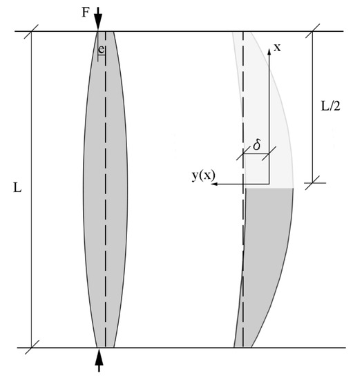
Figure 4.
Deflection of a column with Entasis.
In Equation (14), the deflection is δ- y(x). a = 0 due to symmetry, and since y(0) = 0, then b = 0.
At x = L/2 (ends of the column), then y(x) = δ, and therefore:
If a centrally loaded column of one material is considered, the corresponding Euler force can be determined based on moment equilibrium between the external and internal moment.
For x = 0 this becomes:
It is assumed that the material is linear elastic. If Equation (17) is compared to the Euler load from a straight column, the straight column has a π2/8 times larger Euler force (23%) than the column with Entasis.
Similar to the straight column calculation, it is possible to use the curved “Ritter” working curve. If the column is considered at mid-height (x = 0), then the Rankine force FR0 of the Entasis column becomes:
Again, the cross-section of the composite column consists of multiple materials, which must be taken into account. The same approach is used for the straight column in Equations (7) and (9) to find the ultimate compressive strength Fu and the joined flexural stiffness EI0.
The method from Equation (11) is repeated with the F0 value from Equation (17) due to the assumption of constant curvature, and the eccentricity e and the deflection at mid-height, when the column is loaded with the force F become:
Now, the stresses can be checked in the outermost fibers of the materials in the composite cross-section. The stresses are compared to their tensile and compressive strengths. The check is performed similarly to Equations (12) and (13) for straight columns.
3. Column Tests
Three columns were tested to failure in the Structural Lab at the Technical University of Denmark. The primary aim of the tests was to display the effect of the stabilizing LAC layer around a strong concrete core. The secondary purpose was to verify the calculation method.
The effect of the developed column theory for columns with a regular concrete core and a LAC cover was investigated by load testing to failure with an eccentricity of 10 mm. In the tests, the concrete in the core had a characteristic compressive cylinder strength of 45 MPa, and the LAC had 5 MPa. A reference test was also performed without the LAC layer. All tests were conducted around the weak axis of the core.
The columns were 1.7 m in length, and the cores had a cross-section of 50 mm × 90 mm. The total cross-section, including the LAC, was 180 mm × 190 mm, see Figure 5. Three Y10 reinforcement bars were positioned on each side of the column.
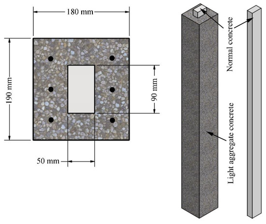
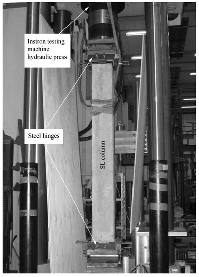
Figure 5.
The geometry of tested column types. Length of core 1800 mm. Length of composite cross-section 1700 mm. Two column tests were conducted with the LAC layer. The tests were performed deformation controlled (rate of 5 mm/min) with eccentricity of 10 mm, and the ends of the columns were hinged (connected to a steel hinge at the end of the core part with a distance of 2000 mm). The setup is seen in Figure 6.
By using the elastic approach presented previously, theoretical calculations using mean strengths yielded a maximum load of 266 kN for columns, including the LAC cover. Nevertheless, the columns were made with a minor prolongation of the core, and a check of the capacity of that part gave a maximum load of only 121 kN (compressive failure). For the column type without the LAC cover, the maximum load was estimated to be 35 kN (instability failure).
The failure occurred as expected in the concrete core at the end of the column in both tests, and the failure load was 128 kN and 122 kN, respectively. The fracture was in the compressed side of the strong concrete. The failure loads were 1% and 6% above the calculated estimate. It was a brittle failure in both SL column specimens, and there were no cracks or sounds before the failure occurred.
The column without the LAC cover was tested under the same conditions, and the failure load was 30 kN. The failure was a relatively brittle bending failure close to the middle of the column. The reason for the brittle failure type was the fact that the column was unreinforced. Several times before the failure, a crunching sound was heard, but no cracks were observed beforehand. The failure types are seen in Figure 7.
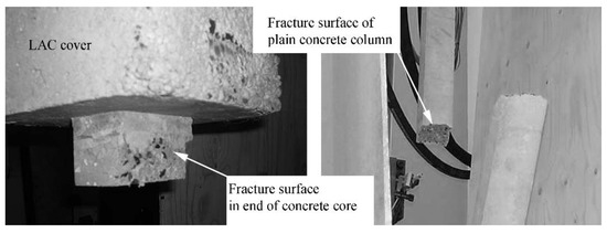
Figure 7.
Failure pattern of SL column (left) and plain concrete core (right).
The tests demonstrated the stabilizing potential of the LAC and how the presented analytical method could be used to estimate the capacity of the columns.
4. The Carbon Footprint from Materials
A concrete member’s carbon footprint or Global Warming Potential (GWP) can be investigated over the whole life cycle [31]. That can include life phases of (A) production and erection, (B) use of the member, (C) end of life, and (D) reuse potential.
Conservatively, only the phases A, B and C are included here, and the CO2 emission numbers are deduced in [30] and verified by comparing to trusted CO2 sources such as the German ÖkobauDat [32]. The CO2 numbers and material properties used in this paper are shown in Table 1. The CO2 equivalent emission values are referred to as “CO2 emission” in the remaining part of the paper.

Table 1.
Material properties used as example in the paper.
In Table 1, the GWP from UHPC cannot be found in databases. 0.14 kgCO2/kg is used in the calculations. The shown interval from 0.11 to 0.19 in the table is estimated in the following way:
According to Hertz and Halding [30], the cement contributes roughly 0.9 kgCO2/kg cement. Transport and processing of aggregates account for approximately 0.1 kgCO2/kg cement, and therefore the emission is close to 1.0 kgCO2/kg cement.
Silica fume has a contribution of 14 kgCO2/tonne [33], which is equal to 0.014 kgCO2/kg silica fume.
Hertz [34] and Bache [35] show recipes of one of the first actual ultra-high-performance concrete types called “Densit”. They have a cement content between 300 and 500 kg/m3 and silica fume content of 100 kg/m3, and both reach approximately 150 MPa of compressive strength.
The GWP is then, e.g., for 300 kg cement and 100 kg silica fume per m3 of concrete with a density of 2680 kg/m3:
5. CO2 Emission Calculation of SL Columns
The CO2 emission can be calculated from different SL column geometries based on the volumes of the concrete types. The columns with Entasis are in focus here to reduce the carbon footprint the most. The results are compared to ordinary concrete columns as a reference.
The method to optimize an SL column with Entasis is as follows:
- Choose the core concrete material properties and the LAC properties;
- Define the normal load, eccentricity, and column length;
- Choose the minimum acceptable thickness of the LAC cover to comply with fire safety requirements;
- Begin with the smallest diameter of the cylindrical core concrete and calculate points a to c below. Subsequently, recalculate points a to c several times with an increasing core diameter.
- Optimize the thickness of the layer of LAC in the middle of the column to fit the required capacity at that location (by using the proposed elastic method);
- Optimize the thickness of the layer of LAC in the ends of the column to fit the required capacity at that location (by using the proposed elastic method). The layer thickness must be equal to or larger than the requirement from point 3;
- Calculate the core and the LAC’s volume or mass and determine the emitted CO2 for the column.
The results of such investigation with different sizes of the diameter of the concrete column core can be plotted to illustrate which geometry is optimal to resist the load while achieving the lowest CO2 emission.
An example is given in Figure 8 for a 10 m long column with an e = 20 mm eccentricity. It is loaded by 100 kN. The concrete core is made of the UHPC Densit with 150 MPa of compressive strength, and the LAC has a density of 900 kg/m3 and compressive strength of 5.0 MPa (see Table 1). The minimum layer thickness of LAC is set to 20 mm. No reinforcement is considered in the example.
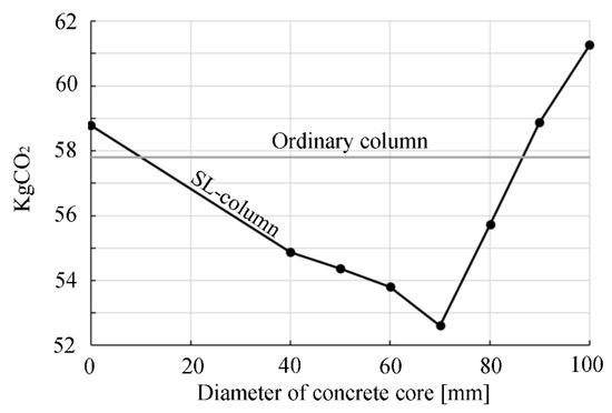
Figure 8.
CO2 emission of example SL column vs. ordinary column of diameter 148 mm.
The SL column CO2 emission results are compared to a regular circular column with 55 MPa compressive strength. The regular cylindrical column requires a diameter of 148 mm to resist the load by the elastic method.
The solution of the composite SL columns emits less CO2 with an optimal core diameter of 70 mm. At that specific core diameter, the required layer of LAC at the column middle is 91 mm, and at the column ends, it is only 21 mm thick. From this point on, increasing the core diameter increases the carbon footprint of the column since the minimum layer thickness of the LAC is reached at the ends.
With a core diameter of 0 mm, the SL column has become a pure LAC column, which gives a higher CO2 emission than the regular column. In practice, it would not be possible to make cores with a small diameter, e.g., below 40 mm, so a suggested valid core diameter interval is from 40 mm to 70 mm for the given setup.
In the above example, the reduction in the emission of CO2 using the specific SL column is 9%. When investigating different column lengths, loads, and eccentricities, there is not always a saving by using SL columns compared to regular columns. Therefore, an investigation of the specific setup is always required to determine whether it is a benefit or not.
The example column of 10 m with 100 kN load was examined for different eccentricities of the load. In Figure 9, the optimal configuration of SL columns (core diameter and LAC Entasis layer thickness) with a 150 MPa UHPC core and a 55 MPa concrete core is compared to a regular column with different load eccentricities. As seen, the SL columns still emit less CO2 than the regular column in as cases. In Figure 10, a similar setup is provided, but now the column length is reduced to 5 m. Here, the normal column has a lower carbon footprint for most eccentricities.
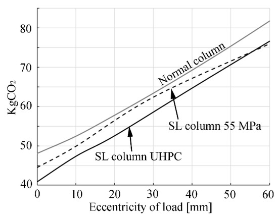
Figure 9.
Example emission of CO2 from SL columns vs. a regular column (10 m, 100 kN load).
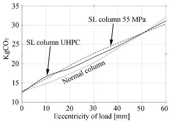
Figure 10.
Example emission of CO2 from SL columns vs. a regular column (5 m, 100 kN load).
The example is expanded to gain an overview of the parameters influencing the carbon footprint reduction compared to regular columns; see Table 2 and Table 3. Here, the optimized SL columns are compared to regular columns with a compressive strength of 55 MPa, and the CO2 emissions are compared as a percentage. A positive number is a decrease in the carbon footprint using the SL column, and a negative number is an increase.
Table 2.
Calculated example of CO2 emission of optimized SL columns of Densit core and LAC with Entasis compared to regular concrete columns.
Table 3.
Calculated example of CO2 emission of optimized SL columns of 55 MPa core and LAC with Entasis compared to regular concrete columns.
The tables indicate that the SL columns are most effective for more slender columns. There is a tendency that the SL column’s carbon footprint is smallest compared to regular columns when the SL columns are:
- Loaded with 100 kN instead of 1000 kN;
- Longer;
- Applied a smaller eccentricity;
- Made with a core of UHPC.
All of the above points from the example provided support that the carbon footprint benefit of SL columns increases with increased column slenderness. The slenderness of the SL columns with simply supported ends is found by:
L is the column length, and i is the radius of gyration based on the flexural stiffness of the cross-section EI (in the middle of the column height) and the axial stiffness EA of the cross-section in the same location. As the number in Equation (21) increases, the column becomes more slender.
The tendency from the examples in Table 2 and Table 3 is shown in Figure 11. Here, the SL column’s slenderness is plotted with the CO2 emission saving of the SL columns. The CO2 emission is still compared to an optimized circular regular concrete column made by 55 MPa concrete. Based on the example results, the SL column type reduces the carbon footprint for slender columns with . For slenderness below that level, a benefit is not certain.
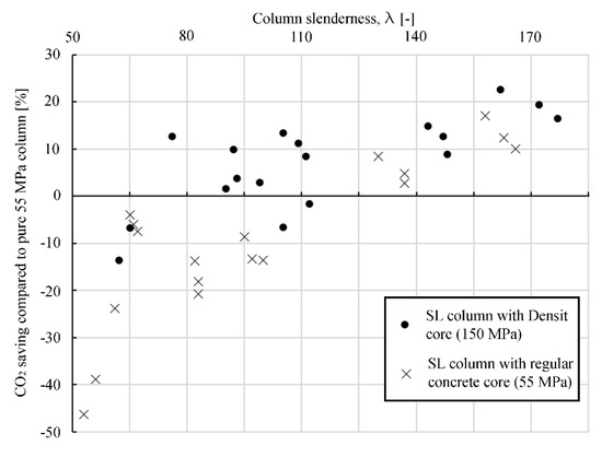
Figure 11.
SL column example CO2 emission compared to regular concrete column. A positive number is a CO2 saving using the SL column with Entasis.
The reason for the improved carbon footprint for slender SL columns is the cross-section configuration, where the SL column is designed to resist buckling optimally with the Entasis shape of LAC. The concept has the most significant potential for slender columns because they tend to fail in buckling.
6. Conclusions
A new hybrid column type is proposed, where a Light Aggregate Concrete (LAC) covers a core of stronger concrete. The column type is called a super-light (SL) column. The reason for having the LAC cover is to stabilize the strong core and protect it from fire. The effect of the LAC enables engineers to use very slender concrete cores of high-strength concrete. Furthermore, the LAC is found to emit less CO2 per volume compared to regular concrete.
An elastic analytical method for calculation of the capacity of columns of two or more materials with an applied eccentric normal load is provided for both straight columns and for columns with Entasis shape (bulging in the middle). The elastic approach requires an uncracked cross-section, which utilizes the material stiffness of both concrete grades. Nevertheless, a future study is to compare the elastic method to a plastic approach with a reinforced cracked cross-section. The elastic solution is always on the safe side to consider.
Two column types were tested with an eccentric normal load to failure in the lab: A straight SL column type with LAC cover (cross-section: 180 mm × 190 mm) and the same column without the LAC cover (50 mm × 90 mm). The tests demonstrated the stabilizing effect of the LAC cover of the slender core since the capacity increases by up to 326% with the LAC layer. The brittle failure occurs as a local fracture in compression at an “outgrowth” at the end of the SL columns core for both tested SL column specimens. Calculations yield a 786% increase in capacity with the LAC cover if the failure in the exposed ends in the tests setup could be avoided.
The tests show that connection details are important to develop for future practical applications in buildings. In the calculation and examples, the columns are assumed to be simply supported, and the practical aspects of creating a pragmatic hinged connection is a central point of future work in the field, perhaps as “design for disassembly”. The failure loads of the tested SL columns are within 6% of the calculated values.
The tests are made with straight columns, and it could be interesting also to investigate the SL columns with Entasis in future tests. That would also require the development of methods for the application of formwork to create the Entasis shape—e.g., via textile molds. One benefit of the LAC is the low mass, which is assumed to enable the use of textile molds due to the reduced mold pressure.
Numbers for the CO2 emission of different types of concrete, high strength concrete, and LAC are provided and used in examples. A further optimization could come from, e.g., the utilization of reused aggregates or green cement.
The carbon footprint is calculated for different SL column examples using a four-step approach to ensure an optimized Entasis shape with variations in the LAC layer thickness providing the Entasis column shape. Only circular cross-sections are considered. The minimum layer thickness of the LAC is 20 mm at the column ends to ensure adequate fire protection of the core. The examples show that the SL columns are not consistently reducing the CO2 emission compared to ordinary straight columns of regular concrete. There is a tendency that the concept is most effective for more slender columns, and the reason is that the design is efficient to resist column buckling.
Further optimization can be performed by optimizing the strength and stiffness of the core and the LAC cover.
Funding
This research received no external funding.
Institutional Review Board Statement
Not applicable.
Data Availability Statement
Not applicable. All analytical methods are provided in the paper. You may contact the author to gain access to the calculated examples.
Acknowledgments
The author wishes to thank Kristian Dahl Hertz for his valuable suggestions and cooperation and also the student and staff at the Structural Lab at DTU for conducting the experiments.
Conflicts of Interest
The author declares no conflict of interest.
Nomenclature
| 0 | Subscript for unloaded condition |
| A | Area |
| c | Subscript for concrete |
| δ | Deflection at midpoint |
| e | Eccentricity |
| E | Elastic modulus |
| ε | Strain |
| EA | Axial stiffness |
| EI | Flexural stiffness |
| F | Applied load |
| fc | Compressive strength |
| FE | Euler load |
| FR | Rankine force |
| ft | Tensile strength |
| Fu | Ultimate compressive load |
| fu | Ultimate strength |
| I | Moment of inertia |
| i | Radius of gyration |
| κ | Curvature |
| L | Column length |
| λ | Column slenderness |
| lc | Subscript for light aggregate concrete |
| σ | Stress |
| S | Subscript for steel |
| y(x) | Deflection shape |
| yc | Distance from outermost fiber to the centroid in compressive side |
| yt | Distance from outermost fiber to the centroid in tension side |
References
- Mirmiran, A.; Shahawy, M. A New Concrete-Filled Hollow FRP Composite Column. Compos. Part B-Eng. 1996, 27, 263–268. [Google Scholar] [CrossRef]
- Hany, N.F.; Hantouche, E.G.; Harajli, M.H. Finite element modelling of FRP-confined concrete using modified concrete damaged plasticity. Eng. Struct. 2016, 125, 1–14. [Google Scholar] [CrossRef]
- Tang, Z.; Li, W.; Tam, V.W.Y.; Yan, L. Mechanical behaviors of CFRP-confined sustainable geopolymeric recycled aggregate concrete under both static and cyclic compressions. Compos. Struct. 2020, 252, 112750. [Google Scholar] [CrossRef]
- Gao, C.; Huang, L.; Yan, L.; Jin, R.; Kasal, B. Strength and ductility improvement of recycled aggregate concrete by polyester FRP-PVC tube confinement. Compos. Part B Eng. 2019, 162, 178–197. [Google Scholar] [CrossRef]
- Leon, R.; Griffis, L. Composite column design. Mod. Steel Constr. 2005, 45, 35–36. [Google Scholar]
- Kibiriya, T. Performance of Concrete Filled Steel Tubular Columns. Am. J. Civ. Eng. Archit. 2017, 5, 35–39. [Google Scholar] [CrossRef]
- Lacki, P.; Derlatka, A.; Kasza, P. Comparison of steel-concrete composite column and steel column. Compos. Struct. 2018, 202, 82–88. [Google Scholar] [CrossRef]
- Lawson, M.; Wickens, P. Steel Designers Manual, 6th ed.; Blackwell Science Ltd.: Oxford, UK, 2008; pp. 651–661. [Google Scholar] [CrossRef]
- Mensinger, M.; Röss, R. Composite column with a bunch of high-strength reinforcement bars. In Proceedings of the XII Conference on Steel and Composite Constructions, Coimbra, Portugal, 21–22 November 2019. [Google Scholar]
- Gonçalves, R.; Carvalho, J. An efficient geometrically exact beam element for composite columns and its application to concrete encased steel I-sections. Eng. Struct. 2014, 75, 213–224. [Google Scholar] [CrossRef]
- Cakiroglu, C.; Islam, K.; Bekdas, G.; Billah, M. CO2 Emission and Cost Optimization of Concrete-Filled Steel Tubular (CFST) Columns Using Metaheuristic Algorithms. Sustainability 2021, 13, 8092. [Google Scholar] [CrossRef]
- Cakiroglu, C.; Islam, K.; Bekdas, G.; Kim, S.; Geem, Z.W. CO2 Emission Optimization of Concrete-Filled Steel Tubular Rectangular Stub Columns Using Metaheuristic Algorithms. Sustainability 2021, 13, 10981. [Google Scholar] [CrossRef]
- Ozbakkaloglu, T. A Novel FRP-Dual-Grade Concrete-Steel Composite Column System. Thin-Walled Struct. 2015, 96, 295–306. [Google Scholar] [CrossRef]
- Yang, Y.; Zhang, H. Experimental study on all-lightweight aggregate concrete columns under eccentric loading. Key Eng. Mater. 2012, 517, 392–397. [Google Scholar] [CrossRef]
- Zhang, X.; Kuang, X.; Yang, J.; Fan, Y. Bearing Capacity of Stone-Lightweight Aggregate Concrete-Filled Steel Tubular Stub Column Subjected to Axial Compression. KSCE J. Civ. Eng. 2019, 23, 3122–3134. [Google Scholar] [CrossRef]
- Almamoori, A.H.N.; Naser, F.H.; Dhahir, M.K. Effect of section shape on the behaviour of thin walled steel columns filled with light weight aggregate concrete: Experimental investigation. Case Stud. Constr. Mater. 2020, 13, e00356. [Google Scholar] [CrossRef]
- Salgar, P.B.; Patil, P.S. Temperature effect on behavior of structural light weight concrete filled steel tube (LWCFST) column. J. Build. Pathol. Rehabil. 2020, 5, 6. [Google Scholar] [CrossRef]
- Wei, H.; Wu, T.; Liu, X.; Zhang, R. Investigation of stress-strain relationship for confined lightweight aggregate concrete. Constr. Build. Mater. 2020, 256, 119432. [Google Scholar] [CrossRef]
- Rafique, N.; Abbass, W.; Abbas, S.; Ahmed, A. Feasibility of textile fabrics for strengthening of concrete column. Constr. Build. Mater. 2020, 259, 119684. [Google Scholar] [CrossRef]
- Zhu, B.; Nematollahi, B.; Pan, J.; Zhang, Y.; Zhou, Z.; Zhang, Y. 3D concrete printing of permanent formwork for concrete column construction. Cem. Concr. Compos. 2021, 121, 104039. [Google Scholar] [CrossRef]
- Vandoros, K.G.; Dritsos, S.E. Concrete jacket construction detail effectiveness when strengthening RC columns. Constr. Build. Mater. 2008, 22, 264–276. [Google Scholar] [CrossRef]
- Bindhu, K.R.; Ansari, S.; Vaisakh, M.S. Seismic behaviour of UHPC columns with various tie configurations. Asian J. Civ. Eng. 2021, 22, 1097–1113. [Google Scholar] [CrossRef]
- Li, J.; Wu, C.; Hao, H.; Liu, Z. Post-blast capacity of ultra-high performance concrete columns. Eng. Struct. 2017, 134, 289–302. [Google Scholar] [CrossRef]
- Stevens, G.P. Entasis of Roman Columns. Univ. Mich. Press 1924, 4, 121–152. [Google Scholar] [CrossRef]
- Johnson, W. Entasis–Mechanics and Illusion. Int. J. Mech. Sci. 1993, 35, 803–808. [Google Scholar] [CrossRef]
- Thompson, P.; Papadopoulou, G.; Vassiliou, E. The origins of Entasis: Illusion, aesthetics or engineering? Spat. Vis. 2007, 20, 531–543. [Google Scholar] [PubMed] [Green Version]
- Grúňová, Z.; Holešová, M. Columnar entasis in Vignola’s and other renaissance works. Civ. Environ. Eng. 2018, 14, 132–137. [Google Scholar] [CrossRef] [Green Version]
- Hertz, K.D.; Halding, P. Sustainable Light Concrete Structures, 1st ed.; Springer: Cham, Switzerland, 2022. [Google Scholar] [CrossRef]
- Hertz, K.D. Design of Fire-Resistant Concrete Structures, 1st ed.; Thomas Thelford: London, UK, 2019. [Google Scholar] [CrossRef] [Green Version]
- Report R-439. DTU Civil Engineering Webpage. Available online: www.byg.dtu.dk/forskning/publikationer/byg_rapporter (accessed on 13 January 2022).
- EN 15804+A2; Sustainability of Construction Works–Environmental Product Declarations–Core Rules for the Product Category of Construction Products. CEN European Committee for Standardization: Brussels, Belgium, 2019.
- Ökobaudat–Sustainable Construction Information Portal. Available online: www.oekobaudat.de/en.html (accessed on 13 January 2022).
- Norchem–The Largest Producer of Silica Fume Products in North America. Available online: https://www.norchem.com/applications-sustainability.html (accessed on 13 January 2022).
- Hertz, K. Heat-induced explosion of dense concretes. Inst. Build. Des.-Rep. 1984, 166, 1–18. [Google Scholar]
- Bache, H.H. Densified cement/ultra-fine particle-based materials. In Proceedings of the Second International Conference on Superplasticizers in Concrete, Ottawa, ON, Canada, 10–12 June 1981. [Google Scholar]
Publisher’s Note: MDPI stays neutral with regard to jurisdictional claims in published maps and institutional affiliations. |
© 2022 by the author. Licensee MDPI, Basel, Switzerland. This article is an open access article distributed under the terms and conditions of the Creative Commons Attribution (CC BY) license (https://creativecommons.org/licenses/by/4.0/).