Abstract
With the goal of carbon peak and carbon neutrality, fossil energy is becoming increasingly exhausted. Optimizing energy structure and saving energy and reducing consumption are the top priority. With the rapid development of modern science and technology, vacuum refrigerator has been greatly applied and popularized in various fields, such as food production, medicine and biology. However, in the actual operation process, the energy consumption of vacuum refrigerator is high, which does not meet the concept of energy conservation and environmental protection. The inner and outer push–pull structure of the sealing door makes it occupy too much space when opening the door, which is very inconvenient. In this paper, a vacuum refrigeration energy-saving device and the TRNSYS 16 software are used to simulate the energy-saving device. The results show that the device can reduce the number of vacuum refrigeration pumps and greatly reduce the loss of energy consumption. In addition, the new sealing door structure can also reduce the space occupied during its expansion and improve the utilization of space.
1. Introduction
In January 2021, at the dialogue meeting of “Davos agenda” of the world economic forum, China proposed to accelerate the adjustment and optimization of industrial structure and energy structure, advocate a green and low-carbon way of production and life, and strive to reach the peak of carbon dioxide emission by 2030 and achieve carbon neutrality by 2060 [1]. At present, China is still the largest energy consumer in the world, and energy consumption is the main carbon dioxide emission source in China [2], accounting for about 88% of all carbon dioxide emissions [3]. With the massive consumption of energy, the energy problem has become one of the common concerns of people. Energy resources are an important material basis for people’s survival and development in society [4]. The utilization and development of energy is related to the development of the whole national economy and the production and life of human beings [5]. Therefore, how to effectively use energy and save energy is the focus of attention now.
Vacuum refrigerators are widely used in vacuum coating, surface treatment, optoelectronics, aerospace, Shi Ying crystals, solar collector tubes, scientific research institutes, biopharmaceuticals, food production, electronic industry, metal processing and other industries [6,7]. A vacuum refrigerator is a piece of refrigeration equipment equipped for vacuum system, which can provide cold source. It has the following characteristic: fast adsorption of water, oil and steam, which can shorten the extraction time by 60–90% and increase the production capacity of the existing vacuum system by 20% to 100%, etc. Roughly speaking, vacuum means that the air pressure in a region is much less than the atmospheric pressure. The energy consumption of processing is the main problem of vacuum freeze-drying technology at present, so it also increases the production cost. Zhou et al. [8] of Shanghai University of Engineering Science put forward that a freeze-dryer system using solar absorption refrigeration in combination with buildings can effectively reduce energy consumption. Through the solar absorption refrigeration system, the cold energy is supplied to the freeze-dryer and buildings at the same time, so that the cold energy can be used step by step. Zhang et al. [9] of Zhejiang University think that the traditional freeze dryer has high running cost and high energy consumption, which limits the wide application of freeze-drying technology. They put forward a freeze dryer based on a closed regeneration loop of hygroscopic solution, made thermodynamic analysis and concluded that the new freeze dryer has high energy saving potential in a wide operating range. Liu et al. [10] of Xi’an Jiaotong University established a mathematical model for exergy analysis of freeze-drying process. The model considered five operations: freezing, primary drying, secondary drying, steam condensation and vacuum pumping, among which the energy consumption loss under freezing and vacuum operation was low. Luo et al. [11] of Shandong Jianzhu University analyzed the energy saving of food freeze-drying, which provided a theoretical basis for how to carry out pretreatment and pre-freezing in the process of freeze-drying and how to control temperature and pressure to shorten the drying time. Rahman et al. [12] of University of Sharjah developed a new air freeze-drying system, evaluated its parameters and compared the drying characteristics and physical quality between vacuum freezing and traditional AFD. The results showed that the system was a suitable and feasible alternative without affecting the quality. Through the vacuum cooling experiment, Han Houde [13] of Shanghai Maritime University obtained that the power consumption of compressor, vacuum pump and other equipment accounted for 68%, 18% and 14% of the total energy consumption respectively and pointed out that about 10 min after the flash, if the compressor was unloaded by 25%, the total energy consumption of the unit could be reduced by about 8%. Several small capacity vacuum pumps are selected for the vacuum device, which are all put into operation before flash, accelerate the vacuum pumping rate, shorten the no-load operation time of the compressor, save the total energy consumption of the compressor, reduce the number of vacuum pumps put into operation after flash and reduce the total energy consumption of the vacuum pump.
However, in the existing studies, there is little research on vacuum freeze-drying driven by a single vacuum refrigeration pump. In the prior art, each vacuum freezer has a separate refrigeration system [14], and when multiple vacuum freezers need to be used at the same time, multiple refrigeration systems need to be equipped at the same time, which leads to higher energy consumption [15]. The market application of vacuum freeze dryer has been seriously hindered by the production projects with high energy consumption in the world, and many environmental problems have followed, which do not conform to the concept of energy conservation and environmental protection. Therefore, it is necessary for us to analyze the energy consumption of vacuum freezers to reduce the energy consumption as much as possible [16]. In addition, the sealing doors of general vacuum refrigerators are of push–pull structure inside and outside, which easily occupies a large space when opening the door. Especially in places where the installation space of vacuum refrigerators is limited, the push–pull design of sealing doors [17] inside and outside is very inconvenient to use. Therefore, the research focus of this paper is to study and analyze the energy consumption optimization of a vacuum refrigerator energy-saving device which only needs a single vacuum refrigeration pump to realize the refrigeration of multiple vacuum refrigerators at the same time. This energy-saving device can reduce the use of vacuum refrigeration pumps [18], optimize the system configuration, effectively reduce its energy consumption and achieve the environmental protection concept of energy saving and emission reduction.
The general idea of this paper is: according to the analysis of the total energy consumption of the vacuum refrigerator, the energy-saving transformation of the general vacuum refrigerator with high energy consumption in the actual operation process is carried out, and a new energy-saving device which can use a single vacuum refrigeration pump to drive multiple vacuum refrigerators through the air-conditioning transmission box is designed. Furthermore, the simulation connection diagrams of four schemes are simulated and designed by TRNSYS 16 software for comparison, setting the simulation parameters and the simulation running time to 8760 h (i.e., one year) for energy consumption analysis and comparison and finally obtaining the results. At the same time, the sealing door structure of the vacuum refrigerator device is creatively designed. The flexible movement of the sealing door is realized through the design of the box door locking mechanism and the box locking mechanism, which can effectively reduce the occupied space and improve the space utilization rate.
2. Energy Consumption of Refrigeration System of Vacuum Refrigerator
The vacuum freezer is the key piece of equipment for the production of freeze-dried preparations, and the refrigeration system is one of the key systems of the vacuum freezer [19]. The refrigeration system mainly provides the low temperature required by freeze drying for the vacuum refrigerator in normal production. The physical state of the refrigerant changes through the action of the compressor, so as to absorb the external heat or release its own heat and achieve the effect of low temperature control.
The measurement of energy consumption of refrigeration system is mainly carried out from the following two aspects [20]: one is the measurement of refrigeration capacity, that is, the measurement of refrigeration capacity produced by refrigerator; the second is the measurement of energy consumption, that is, the energy consumed by the refrigerator to produce these cold quantities. Through the test results of refrigerating capacity and energy consumption, the working condition of the refrigerator is analyzed, and the factors leading to higher energy consumption of the refrigerator in operation are found. The refrigeration system is diagnosed and measures are taken to make the refrigerator run with energy saving and high efficiency.
The measuring method of refrigerating capacity of refrigeration unit is to measure the flow rate of cold water and the temperature of inlet and outlet and calculate the refrigerating capacity by the following Formula (1) [21]:
—refrigeration capacity produced by refrigerator, (kW);
—specific heat capacity of cold water, (kJ/(kg·°C));
—cold water flow, (kg/s);
—cold water inlet temperature of refrigerator, (°C);
—cold water outlet temperature of refrigerator, (°C).
The energy consumption of the refrigerator is calculated according to the following Formula (2) by measuring or reading the current, voltage and power factor of the refrigerating unit:
—power consumption of refrigerator, (kW);
—ac voltage value, (V);
—ac current value, (A);
—power factor.
Among them, ac voltage is measured by voltmeter on distribution cabinet; ac current is measured by ammeter on distribution cabinet; and power factor is measured by power factor meter.
In the proportion of total energy consumption of vacuum refrigerator, the power consumption of compressor, vacuum pump and other equipment accounts for about 68%, 18% and 14% of the total energy consumption respectively [13]. From the above analysis, it can be seen that the compressor and vacuum refrigeration pump are the main energy consumption parts. Therefore, the current main energy-saving measures are mainly aimed at the compressor and vacuum refrigeration pump. The adjustment of cooling capacity and energy consumption of vacuum refrigeration pump can be achieved by controlling the pumping speed of vacuum refrigeration pump or the number of vacuum refrigeration pumps. Therefore, the following will introduce a new energy-saving device of vacuum refrigerator to explore the impact of the number of vacuum refrigeration pumps on the total energy consumption of vacuum refrigerator.
3. A Novel Energy-Saving Device of Vacuum Refrigerator
In this paper, an energy-saving device of vacuum freezer is introduced, which can realize refrigeration of multiple vacuum freezers at the same time with only one vacuum refrigeration pump. The energy-saving device has applied for Chinese patent (national application number: CN202110091271.2), and its structure diagram is shown in Figure 1.
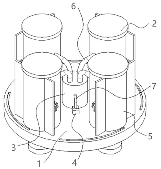
Figure 1.
Energy saving device of vacuum refrigerator. 1—base, 2—vacuum freezing storage tank, 3—cold air conveying box, 4—vacuum refrigeration pump, 5—sealing door, 6—conveying pipe, 7—air duct.
3.1. Composition of Energy-Saving Device
The energy-saving device of vacuum refrigerator is shown in Figure 1. The energy-saving device consists of a base, a cold air delivery box, a vacuum refrigeration pump, a delivery pipe and an air duct and a number of vacuum refrigeration storage tanks, etc.
The device comprises a base. The upper surface of the base is fixedly connected with a vacuum freezing storage tank in a circumferential direction. The center of the upper surface of the base is fixedly connected with a cold air conveying box. A conveying pipe is arranged at the top of the cold air conveying box. One end of the conveying pipe penetrates through the inner wall of the vacuum freezing storage tank. A vacuum pump is fixedly arranged on the upper surface of the base. The output end of that vacuum pump is fixedly connected with an air duct. A first mounting plate is symmetrically fixed on the outer wall of the vacuum freezing storage tank. One side of that first mount plate is provided with a mounting groove. A sealing door is clamped inside the installation groove.
3.2. Connection Mode of Energy-Saving Device Components
The connection mode of each component is as follows: a cold air delivery box is arranged at the center of the base. A vacuum refrigeration pump is arranged on the base and connected with the cold air delivery box through an air duct. A number of vacuum freezing storage tanks are circumferentially distributed on the base around the outside of the cold air conveying tank, and each vacuum freezing storage tank is connected with the cold air conveying tank through a conveying pipe.
3.3. Specific Embodiments of Energy-Saving Devices
In this embodiment, it is preferred that the base is in the shape of a disc, the cold air conveying box is arranged at the center of the disc, one end of the air duct is connected with the top of the cold air conveying box and the other end is connected with the vacuum freezing storage tank. The cold air in the cold air conveying box can be transmitted to each vacuum freezing storage tank to realize the low temperature control inside the vacuum freezing storage tank. As shown in Figure 1, there are four vacuum freezing tanks, which are evenly distributed near the edge of the disc. The vacuum refrigeration pump is installed on the upper surface of the base and communicates with the cold air delivery box through an air duct. In this embodiment, it is further preferred that both the cold air delivery box and the vacuum freezing storage tank are provided with insulation layers.
As shown in Figure 2, in which Figure 2a is a schematic side view of the energy-saving device of the vacuum freezer with the sealing door closed, we can see the base located below, and the sealing door is arranged on the outward side of the vacuum freezer tank. Figure 2b is a partially enlarged schematic diagram of the area A in Figure 2a, which is a part of the box locking mechanism. The area A is arranged on the vacuum freezing storage tank and includes a positioning plate, a first mounting plate perpendicular to the positioning plate, a second mounting plate parallel to the positioning plate and a limit clip passing through the mounting plate.
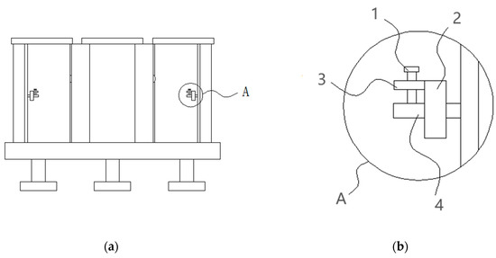
Figure 2.
Schematic side view of energy saving device of vacuum refrigerator. (a) schematic side view of energy-saving device of vacuum freezer with closed sealing door; (b) partial enlarged schematic diagram of area A. 1—limit clip, 2—first mounting plate, 3—second mounting plate, 4—positioning plate.
As shown in Figure 3, in which Figure 3a is a structural schematic diagram of the energy-saving device of the vacuum freezer without the sealing door, we can clearly see the situation inside the vacuum freezer. It can be seen that the chute is composed of an annular chute (a section of arc chute) which is arranged outside the vacuum freezing storage tank and runs along the circumferential direction of the cold air delivery tank, and a radial chute which is arranged between the outward side of the vacuum freezing storage tank and the annular chute. Furthermore, preferably, one end of the circumferential chute is located in front of the outward side of the vacuum freezing tank, and the radial chute is connected with the end of the circumferential chute. Figure 3b is a partially enlarged schematic diagram of area B in Figure 3a, which is also a part of the box locking mechanism. The area B is arranged on the vacuum freezing storage tank and includes a first mounting plate perpendicular to the positioning plate and a second mounting plate parallel to the positioning plate. The first mounting plate is provided with a mounting slot for the positioning plate to pass through, and the second mounting plate is provided with a second limiting hole.
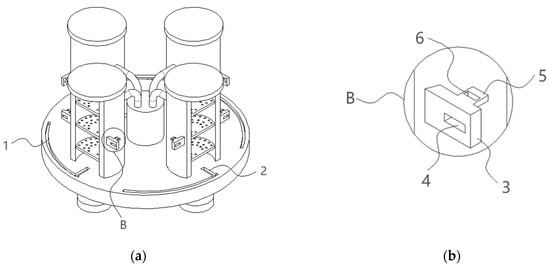
Figure 3.
Schematic diagram of the structure of the energy-saving device of the vacuum refrigerator (the sealing door is not shown). (a) Structural schematic diagram of the energy-saving device of the vacuum freezer without the sealing door; (b) partial enlarged schematic diagram of area B. 1—circumferential chute, 2—radial chute, 3—first mounting plate, 4—mounting groove, 5—second mounting plate, 6—second limiting hole.
As shown in Figure 4, in which Figure 4a is a schematic diagram of the front structure of the sealing door, it is preferred that the sealing door is composed of a sealing door body for sealing with the vacuum freezing storage tank and support plates symmetrically arranged on both sides of the sealing door body. This constitutes a door locking mechanism, which includes a positioning plate and a first limiting hole provided on the positioning plate. Figure 4b is a left structural diagram of the sealing door, which is also a part of the locking mechanism of the box body. Preferably, the chute assembly consists of a chute arranged on the base and a limit slider arranged at the bottom of the sealing door and slidably connected with the chute. Further, it is preferable that the sealing door body is filled with an insulating layer, as shown in Figure 4c,d.
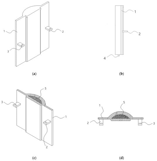
Figure 4.
Schematic diagram of related structure of sealing door. (a) Front view; (b) side view; (c) interior view; (d) top view. 1—support plate, 2— positioning plate, 3—first limit hole, 4—limit slider, 5—insulation layer.
From the above Figure 1, Figure 2, Figure 3 and Figure 4, it can be seen that the sealing door is arranged on the outward side of the vacuum freezing storage tank, and the sealing door can move in the circumferential direction relative to the cold air delivery tank on the base through the chute assembly to realize opening and closing and can be locked with the vacuum freezing storage tank in the closed state through the locking assembly. Preferably, the locking assembly comprises door locking mechanisms arranged on two supporting plates and box locking mechanisms symmetrically arranged on both sides of the vacuum freezing storage tank and matched with the door locking mechanisms. The locking assembly also includes a limiting clip penetrating through the first limiting hole and the second limiting hole (from top to bottom), which is used for realizing the stable attachment between the sealing door and the vacuum freezing storage tank.
3.4. Working Principle of Energy-Saving Device
In use, the samples to be stored are placed in each vacuum freezing storage tank, and then the sealing door slides along the circumferential chute. When the limit slider at the bottom of the sealing door slides along the circumferential chute to the radial chute, the sealing door is pushed along the radial chute toward the vacuum freezing storage tank until the positioning plate on the sealing door is inserted into the mounting groove on the first mounting plate. At this time, the first limiting hole is just opposite to the second limiting ole, and the limiting clip is inserted into the first limiting hole and the second limiting hole, so that the sealing door is fixedly installed on the vacuum freezing storage tank and the interior of the vacuum freezing storage tank is insulated. When all the vacuum freezing storage tanks are in a sealed state, the vacuum refrigeration pump is started, and the cold air in the cold air conveying box is delivered to each vacuum freezing storage tank through a number of delivery pipes.
4. Simulation Design of Energy Saving Device
In order to analyze the energy-saving effect of the vacuum refrigerator energy-saving device, this paper adopts the software TRNSYS [22] developed by the Solar Energy Laboratory of the University of Wisconsin in the United States. Among them, TRNSYS 16 version is used in this paper.
4.1. Simulation Modeling of Energy-Saving Device of Vacuum Freezer
Using TRNSYS 16 real-time simulation software, this energy-saving device is simulated throughout the year. In order to make a better comparison and get the results, we designed four schemes. The four schemes are as follows: in Scheme 1, a group of absorption refrigeration units corresponds to a single vacuum refrigeration pump; in Scheme 2, one set of absorption refrigeration units corresponds to four vacuum refrigeration pumps; in Scheme 3, two groups of absorption refrigeration units correspond to a single vacuum refrigeration pump; in Scheme 4, a group of absorption refrigeration units corresponds to two vacuum refrigeration pumps.
The TRNSYS 16 simulation connection diagram is constructed according to the structure shown in Figure 1. This is the first scheme, which has a set of absorption refrigeration units and a single vacuum refrigeration pump, and the simulation connection diagram is shown in Figure 5.
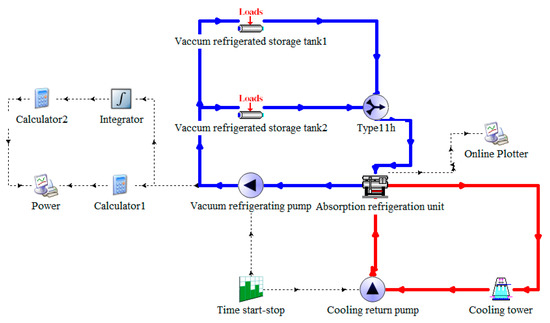
Figure 5.
Scheme 1: simulation connection diagram of energy-saving device of vacuum refrigerator.
As shown in Figure 5, the blue road map is the refrigerant water road map, the red road map is the cooling water circulation road map and the rest of the dotted lines are the data output routes.
In order to reflect the energy-saving characteristics of this device, a simulation connection diagram of the control device is constructed according to the same principle. This is the second scheme, which has a set of absorption refrigeration and four vacuum refrigeration pumps, and its simulation connection diagram is shown in Figure 6.
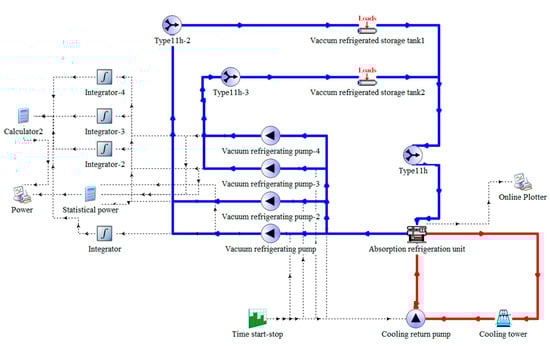
Figure 6.
Scheme 2: simulation connection diagram of control device.
Then, the simulation connection diagram of Scheme 3 and Scheme 4 is constructed. Scheme 3 has two groups of absorption refrigeration units and a single vacuum refrigeration pump, and its simulation connection diagram is shown in Figure 7 below. Scheme 4 has a set of absorption refrigeration units and two vacuum refrigeration pumps, and its simulation connection diagram is shown in Figure 8 below.
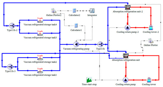
Figure 7.
Scheme 3: simulation connection diagram of a single vacuum refrigeration pump.

Figure 8.
Scheme 4: simulation connection diagram of two vacuum refrigeration pumps.
4.2. Simulation Parameter Setting
The absorption refrigeration unit used in this paper is lithium bromide water absorption refrigeration unit. Because the selection of lithium bromide absorption refrigeration unit should consider the refrigerant itself and the cooling capacity loss of water system, it should generally be 10–15% larger than the calculated cooling load of air conditioning. To simulate the energy-saving effect of vacuum refrigeration pump, through the online survey data and referring to the model parameters of units on the market, this paper takes xz-30 refrigeration unit as the cooling supply of the simulation system. In the simulation connection diagrams shown in Figure 5, Figure 6, Figure 7 and Figure 8 above, the refrigerating capacity of the absorption refrigeration unit is 348.8 kW, and the evaporation consumption is less than 900 kg/h. So the rated COP value is set to 2.58, and the inlet temperature of cooling water is 32 ℃; the flow rate of refrigerant water and cooling water is set at 90,000 kg/h. Each absorption refrigeration unit is equipped with one cooling tower, the maximum flow rate is 324,000 m3/h and the maximum power of fans is 7.5 kW. The rated power of each vacuum refrigeration pump is set to 15 kW, and the rated power of the cooling water return pump is also set to 15 kW. The time start/stop device controls the start/stop state of the vacuum refrigeration pump and the cooling water return pump and is set to work from 10:00 a.m. to 10:00 p.m. every day.
4.3. Selection of Simulation Module
In this paper, the absorption refrigeration unit adopts type-107, the vacuum refrigeration pump and cooling circulating water pump adopt type-114, the vacuum refrigeration storage tank adopts type-682, the time starter and stop adopts type-14 h, the real-time display and power adopt type-65c, the cooling tower adopts type-51b and the type-11 h is the combined three-way valve, which is used to transfer the chilled water in the absorption refrigeration unit. Furthermore, the shunt flows through the vacuum freezing storage tank and then recombines together to achieve the purpose of chilled water circulation.
4.4. Simulation Running Results
The running time of the simulation connection diagram of this energy-saving device is set to 8760 h (i.e., one year), and the daily working time is from 10:00 a.m. to 10:00 p.m. TRNSYS 16 software can generate the following simulation data diagram by clicking the run button through the simulation module adopted by the user and the set parameter values.
- 1.
- According to the simulation Scheme 1 of TRNSYS 16 software, when the rated power of a vacuum refrigeration pump is 15 kW, it can be concluded that the annual cumulative energy consumption of a group of absorption refrigeration units corresponding to a single vacuum refrigeration pump is 54,750 kWh, as shown in Figure 9. At the same time, it can be concluded that the annual refrigerating capacity of a single vacuum refrigeration pump is 32,400 kW, as shown in Figure 10.
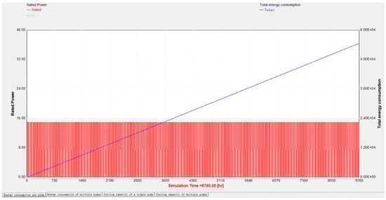 Figure 9. Scheme 1: annual cumulative energy consumption of a single vacuum refrigeration pump (unit: kWh).
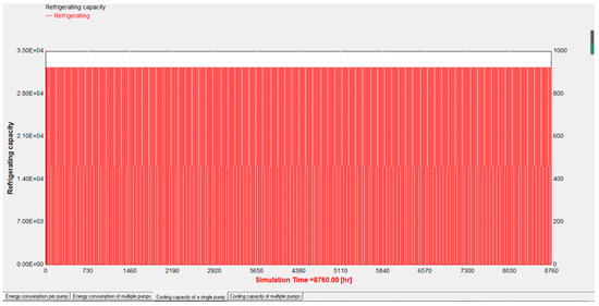 Figure 10. Scheme 1: annual cooling capacity of a single vacuum refrigeration pump (unit: kW).
- 2.
- According to the simulation Scheme 2 of TRNSYS 16 software, when the rated power of one vacuum refrigeration pump is 15 kW, that is, the total power of the four vacuum refrigeration pumps is 60 kW, it can be concluded that the annual cumulative energy consumption of a group of absorption refrigeration units corresponding to the four vacuum refrigeration pumps is 219,000 kWh, as shown in Figure 11. At the same time, it can be concluded that the annual refrigerating capacity of several vacuum refrigeration pumps is 64,800 kW, as shown in Figure 12.
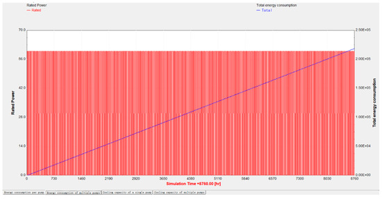 Figure 11. Scheme 2: annual cumulative energy consumption of several vacuum refrigeration pumps (unit: kWh).
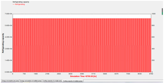 Figure 12. Scheme 2: annual cooling capacity of several vacuum refrigeration pumps (unit: kW).
- 3.
- According to the simulation Scheme 3 of TRNSYS 16 software, when the rated power of a vacuum refrigeration pump is 15 kW, it can be concluded that the annual cumulative energy consumption of two groups of absorption refrigeration units corresponding to a single vacuum refrigeration pump is 54,750 kWh, as shown in Figure 13. At the same time, it can also be concluded that the annual refrigeration capacity of a single vacuum refrigeration pump is 64,800 kW, and its refrigeration capacity is the sum of refrigeration capacity 1 and refrigeration capacity 2, as shown in Figure 14.
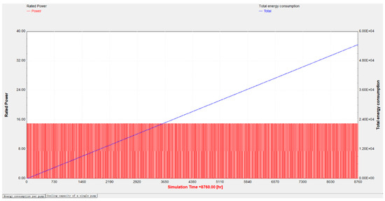 Figure 13. Scheme 3: annual cumulative energy consumption of a single vacuum refrigeration pump (unit: kWh).
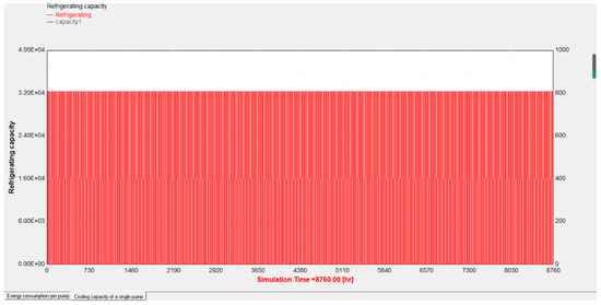 Figure 14. Scheme 3: annual cooling capacity of a single vacuum refrigeration pump (unit: kW).
- 4.
- According to the simulation Scheme 4 of TRNSYS 16 software, when the rated power of one vacuum refrigeration pump is 15 kW, that is, when the total power of the two vacuum refrigeration pumps is 30 kW, it can be concluded that the annual cumulative energy consumption of a group of absorption refrigeration units corresponding to the two vacuum refrigeration pumps is 109,500 kWh, as shown in Figure 15. At the same time, it can be concluded that the annual refrigerating capacity of several vacuum refrigeration pumps is 64,800 kW, as shown in Figure 16.
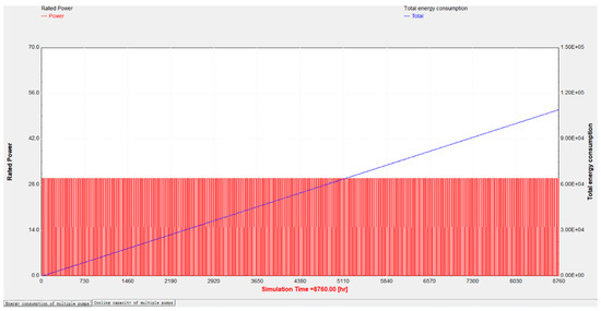 Figure 15. Scheme 4: annual cumulative energy consumption of two vacuum refrigeration pumps (unit: kWh).
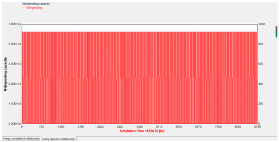 Figure 16. Scheme 4: annual cooling capacity of two vacuum refrigeration pumps (unit: kW).
4.5. Analogue Data Analysis
According to the above Figure 9, Figure 10, Figure 11, Figure 12, Figure 13, Figure 14, Figure 15 and Figure 16, in Scheme 1, when a single vacuum refrigeration pump works all year round at rated power of 15 kW, the accumulated energy consumption is 54,750 kWh, and the refrigerating capacity provided by a single vacuum refrigeration pump is 32,400 kW. In Scheme 2, it can be seen from the data diagram that several vacuum refrigeration pumps work all year round at rated power of 15 kW, that is, when the total power is 60 kW and the accumulated energy consumption is 219,000 kWh. On average, the accumulated energy consumption of many vacuum refrigeration pumps is the same as that of a single vacuum refrigeration pump, but the refrigerating capacity of many vacuum refrigeration pumps is 64,800 kW, and the average refrigerating capacity of each vacuum refrigeration pump is 16,200 kW, which is 50% less than that provided by a single vacuum refrigeration pump when working. Scheme 3 also works in the whole year with the rated power of 15 kW, and the accumulated energy consumption is 54,750 kWh, but in this scheme, when two absorption refrigeration units correspond to a single vacuum refrigeration pump, the refrigeration capacity provided by them is 64,800 kW. In Scheme 4, two vacuum refrigeration pumps work at rated power all year round, and the accumulated energy consumption is 109,500 kWh. Compared with Scheme 2, the refrigeration capacity provided is also 64,800 kW. The difference is that Scheme 4 can provide refrigeration for four vacuum refrigeration tanks.
Therefore, under the same energy consumption, the same load conditions and the same power and energy consumption, when a number of refrigeration pumps operate, the refrigeration capacity provided by a single refrigeration pump is worse than that provided by a single refrigeration pump. This causes some of the refrigeration pumps to be in a working state of wasting energy consumption, resulting in excessive energy consumption, unnecessary consumption and increased operation cost. Therefore, under the same circumstances, using a single vacuum refrigeration pump can reduce the use of vacuum refrigeration pumps, thus reducing the number of vacuum refrigeration pumps put into operation, reducing the energy consumption of vacuum refrigeration pumps, effectively reducing the total energy consumption loss of the energy-saving device and finally achieving the effect of energy saving and emission reduction.
5. Discussions
- According to the simulation of the whole-year operation of the energy-saving device of the vacuum refrigerator by TRNSYS 16 software, it can be seen from the simulated data that compared with the original existing technology, when the rated power is 15 kW, the energy consumption accumulated by a single vacuum refrigeration pump in the whole year is the same as that accumulated by each vacuum refrigeration pump averaged by a number of vacuum refrigeration pumps, which is 54,750 kWh. However, the refrigerating capacity of a single vacuum refrigeration pump is 50% higher than the average refrigerating capacity of each vacuum refrigeration pump, which is 32,400 kW. Therefore, the vacuum freezer avoids the waste of energy taste and can achieve the effect of saving energy and reducing consumption.
- Comparing the third scheme with the first scheme, it can be seen that when a single vacuum refrigeration pump corresponds to two refrigeration units, the refrigeration capacity provided is 64,800 kW, and cold air is provided for four vacuum refrigeration tanks. For comparison, Scheme 1 of two groups need two vacuum refrigeration pumps to supply cold air to four vacuum refrigeration tanks. It can be seen from the comparison between Scheme 1 and Scheme 3 that only one vacuum refrigeration pump is needed in Scheme 3 to supply refrigeration to four vacuum refrigeration storage tanks, which effectively reduces the use of vacuum refrigeration pumps and greatly reduces the energy consumption in operation.
- Comparing Scheme 4 with Scheme 2, in Scheme 4, only two vacuum refrigeration pumps are needed, which can provide refrigeration for four vacuum refrigeration storage tanks under the condition of reaching the same refrigeration capacity of 64,800 kW. So it can be seen that in Scheme 2, two of the four vacuum refrigeration pumps operating all year round are in a no-load state, which undoubtedly increases the operation energy consumption and working cost. However, there is also a problem in Scheme 4 that the average distribution of refrigeration capacity of each vacuum freezing storage tank is not as much as that in Scheme 2, which may result in the technological requirements of frozen materials not being able to be met. Therefore, the relationship between advantages and disadvantages in Scheme 4 still needs to be judged separately.
- In today’s technology, each vacuum refrigerator, i.e., vacuum refrigeration storage tank, has a separate refrigeration system. However, when multiple vacuum refrigeration storage tanks are required for production at the same time, multiple refrigeration systems need to be independently connected with multiple vacuum refrigeration pumps to transport chilled water to achieve the purpose of refrigeration. In this way, increasing the use of multiple refrigeration pumps will lead to high energy consumption. The refrigeration capacity of the system is provided by the chilled water of the absorption refrigeration unit, and the vacuum refrigeration pump is used to transport the chilled water to the vacuum refrigeration storage tank. Compared with Scheme 1 and Scheme 3, although Scheme 3 can meet the premise of reducing energy consumption with one vacuum refrigeration pump, the refrigeration capacity provided is twice that of Scheme 1. However, there is the question as to whether increasing the use of pumps will really affect the cooling capacity. According to Schemes 1, 2, and 4, it is not that increasing the number of vacuum refrigeration pumps can affect the rate of conveying chilled water and improve the refrigeration capacity. On the contrary, it may make the transportation speed of chilled water too fast and affect the heat exchange with the materials in the vacuum refrigeration storage tank. The contact time is too short, resulting in poor refrigeration effect, futile increase in the number of refrigeration pumps and increased energy consumption.
6. Conclusions
- Compared with the prior art, the energy-saving device can realize the refrigeration of a number of vacuum freezers at the same time with only one vacuum refrigeration pump, thereby greatly reducing the use of the vacuum refrigeration pump, greatly reducing the energy consumption and meeting the environmental protection concept of energy conservation and emission reduction.
- According to the device, the sealing door can slide along the circumferential chute and the radial chute through the design of the circumferential chute, the radial chute, the sealing door, the second limiting hole, the first limiting hole and the limiting clamping strip, so that the flexible movement of the sealing door on the base is realized, the occupied space of the sealing door is greatly reduced and the utilization rate of space is greatly improved.
- Compared with conventional devices, the energy-saving device has remarkable energy-saving effect and can save energy and reduce consumption and refrigeration operation cost by reducing the use of vacuum refrigeration pumps put into operation.
- The limitation of this work is that it is currently in the stage of simulation theory experiment. At present, there are few relevant studies on reducing energy consumption by driving multiple vacuum refrigeration storage tanks by a single vacuum refrigeration pump. The simulation content of this paper may have some deviation in the actual situation, and the results need to be verified through further research, analysis and practice.
Author Contributions
Conceptualization, N.Z. and Y.G.; methodology, N.Z.; software, W.Y.; validation, N.Z., Y.G. and Y.L.; formal analysis, N.Z.; investigation, N.Z.; resources, Y.G.; data curation, N.Z. and W.Y.; writing—original draft preparation, N.Z.; writing—review and editing, N.Z.; visualization, N.Z.; supervision, Y.G. and Y.L.; project administration, Y.G.; funding acquisition, Y.G. All authors have read and agreed to the published version of the manuscript.
Funding
This paper is supported by National Natural Science Foundation of China (Grant No. 51606116) and Major Scientific and Technological Research Projects of Shanghai Science and Technology Commission (Grant No. 19195810800).
Institutional Review Board Statement
Not applicable.
Informed Consent Statement
Not applicable.
Data Availability Statement
The data presented in this study are available on request from the corresponding author.
Conflicts of Interest
The authors declare no conflict of interest.
References
- Xi Jinping’s Special Speech at the World Economic Forum’s Davos Agenda Dialogue. Available online: Https://baijiahao.baidu.com/s?id=1689862031132475454&wfr=spider&for=pc (accessed on 25 January 2021).
- Huang, J.; Jiao, F. Research on the coupling relationship between energy consumption and carbon emission in view of high-quality development of economy. Ecol. Econ. 2021, 37, 22–27+34. [Google Scholar]
- BP Statistical Review of World Energy; BP: London, UK, 2020.
- Hu, X. Energy Management; Aerospace Press: Beijing, China, 1993; pp. 6–8. [Google Scholar]
- Wu, Y. Energy-the motive force of human society’s production and life. Econ. Geogr. 1983, 1, 72–76. [Google Scholar]
- Du, M.; Chen, J. Validation method of vacuum freeze dryer. Metrol. Meas. Technol. 2018, 45, 51–53. [Google Scholar]
- Ren, H. Vacuum freeze drying technology and its application in the field of traditional Chinese medicine. Mech. Electr. Inf. 2016, 4, 12–21. [Google Scholar]
- Zhou, Z.; Guo, Y.; Lin, Y. Energy-saving evaluation of a solar integrated vacuum freeze-dryer and building air conditioning system. Energy Explor. Exploit. 2021, 39, 608–619. [Google Scholar] [CrossRef] [Green Version]
- Zhang, S.; Luo, J.; Chen, G.; Wang, Q. Thermodynamic analysis of a freeze-dryer utilizing hygroscopic solution. Dry. Technol. 2018, 36, 697–708. [Google Scholar]
- Liu, Y.; Zhao, Y.; Feng, X. Exergy analysis for a freeze-drying process. Appl. Therm. Eng. 2007, 28, 675–690. [Google Scholar] [CrossRef]
- Luo, N.; Shu, H. Analysis of Energy Saving during Food Freeze Drying. Procedia Eng. 2017, 205, 3763–3768. [Google Scholar] [CrossRef]
- Rahman, S.M.A.; Saidur, R. A novel atmospheric freeze dryer using simultaneous application of subzero and hot air streams using a vortex chiller. Dry. Technol. 2016, 34, 1406–1413. [Google Scholar] [CrossRef]
- Han, H. Energy Consumption Analysis and Energy Saving Technology Research of Vacuum Refrigeration Equipment. Chin. J. Refrig. Technol. 1994, 4, 16–21. [Google Scholar]
- Yan, G.; Liu, Y.; Qian, S.; Yu, J. Theoretical study on a vapor compression refrigeration system with cold storage for freezer applications. Appl. Therm. Eng. 2019, 160, 114091. [Google Scholar] [CrossRef]
- Ana, G.R.G.; Pieter, J.V.B.; Steven, D.M.; Thomas, D.B.; Jos, C.; Jo, D. Analysis of a pharmaceutical batch freeze dryer: Resource consumption, hotspots, and factors for potential improvement. Dry. Technol. 2019, 37, 1563–1582. [Google Scholar]
- Wang, J.; Wang, W.; Ren, X.; Jia, Y. Exergy analysis of the vapor compression refrigeration. J. Hebei Univ. Eng. Nat. Sci. Ed. 2008, 4, 71–73+80. [Google Scholar]
- Ma, L. Design and structural optimization of sealing trolley in liquid batching line. Wuhan Polytech. Univ. 2018. [Google Scholar]
- Yuan, Y. Study on energy saving of vacuum cooling device. Mech. Electr. Equip. 2008, 4, 23–26+31. [Google Scholar]
- He, T.; Chen, P. Analysis and treatment of common faults in refrigeration system of freeze dryer. Mech. Electr. Inf. 2021, 9, 20–21. [Google Scholar]
- Wang, J. Analysis of common problems in refrigeration system of freeze dryer. Sci. Techno. Vis. 2014, 4, 91. [Google Scholar]
- Bai, X.; Sun, C.; Guo, L.; Wang, H. Tests and analysis on energy consumption of heating ventilating and air-conditioning systems in commercial buildings. J. Chongqing Univ. 2008, 6, 637–641. [Google Scholar]
- Xie, Z.; Gong, Y.; Ye, C.; Yao, Y.; Liu, Y. Numerical Analysis and Optimization of Solar-Assited Heat Pump Drying System with Waste Heat Recovery Based on TRNSYS. Processes 2021, 9, 1118. [Google Scholar] [CrossRef]
Publisher’s Note: MDPI stays neutral with regard to jurisdictional claims in published maps and institutional affiliations. |
© 2022 by the authors. Licensee MDPI, Basel, Switzerland. This article is an open access article distributed under the terms and conditions of the Creative Commons Attribution (CC BY) license (https://creativecommons.org/licenses/by/4.0/).