
A Comparison between On-Site Measured and Estimated Based Adjustment Factor Values Used to Calculate Heat Losses to Unconditioned Spaces in Dwellings


Abstract
:1. Introduction
2. Research Fundamentals and Significance
2.1. The Concept of Adjustment Factor for Unheated Spaces
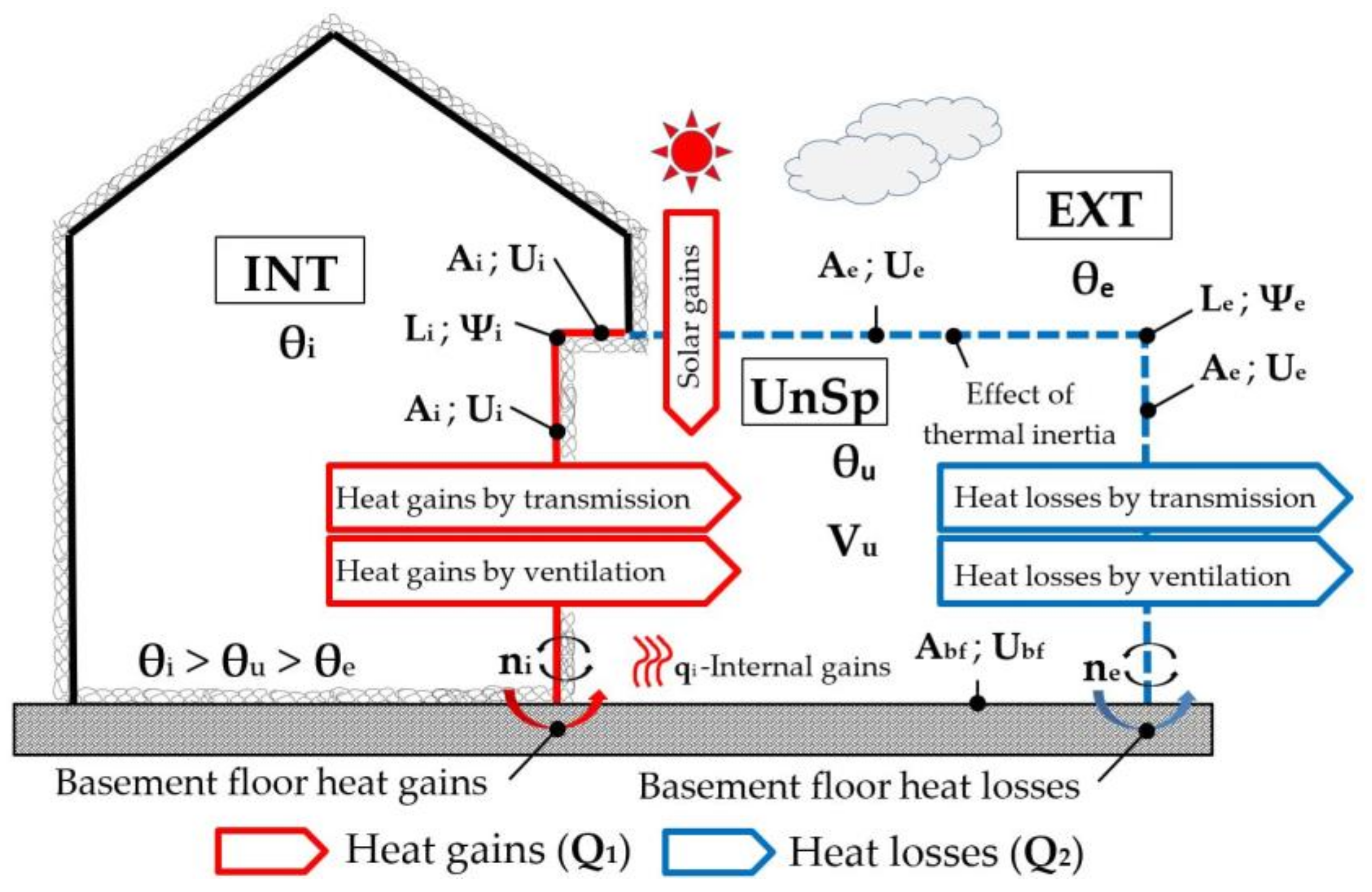
2.2. Energy Balance in Unheated Spaces
2.3. Simplifications in Thermal Loss Analysis for Unheated Spaces
2.3.1. EN ISO 13789
2.3.2. TGD-L2021
BR 443
TGD-L
2.3.3. RCCTE
2.3.4. REH/DEE
2.3.5. DB-HE
2.3.6. RE2020
2.3.7. UNI/TS
3. Materials and Methods
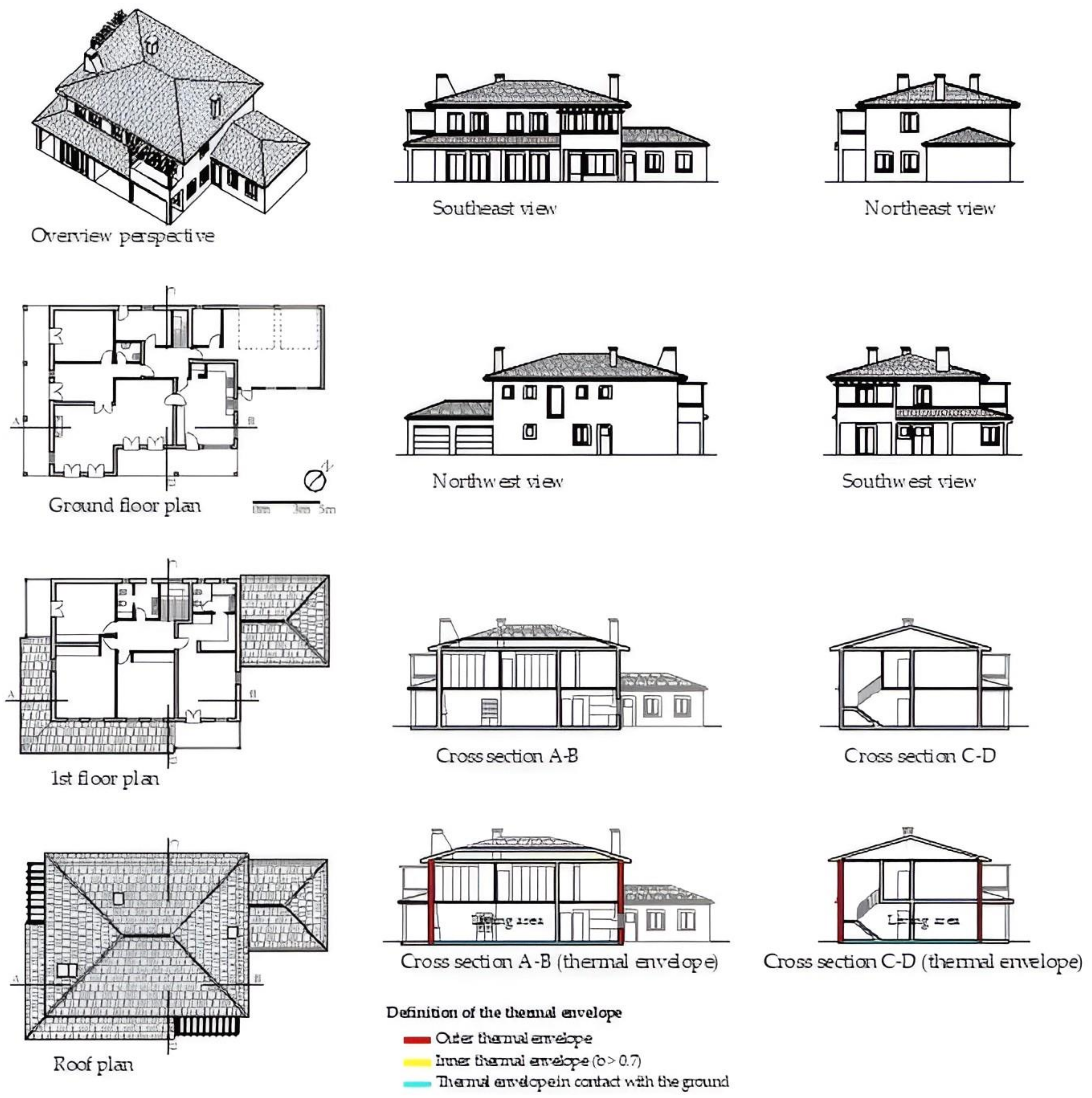
3.1. Case Study 1
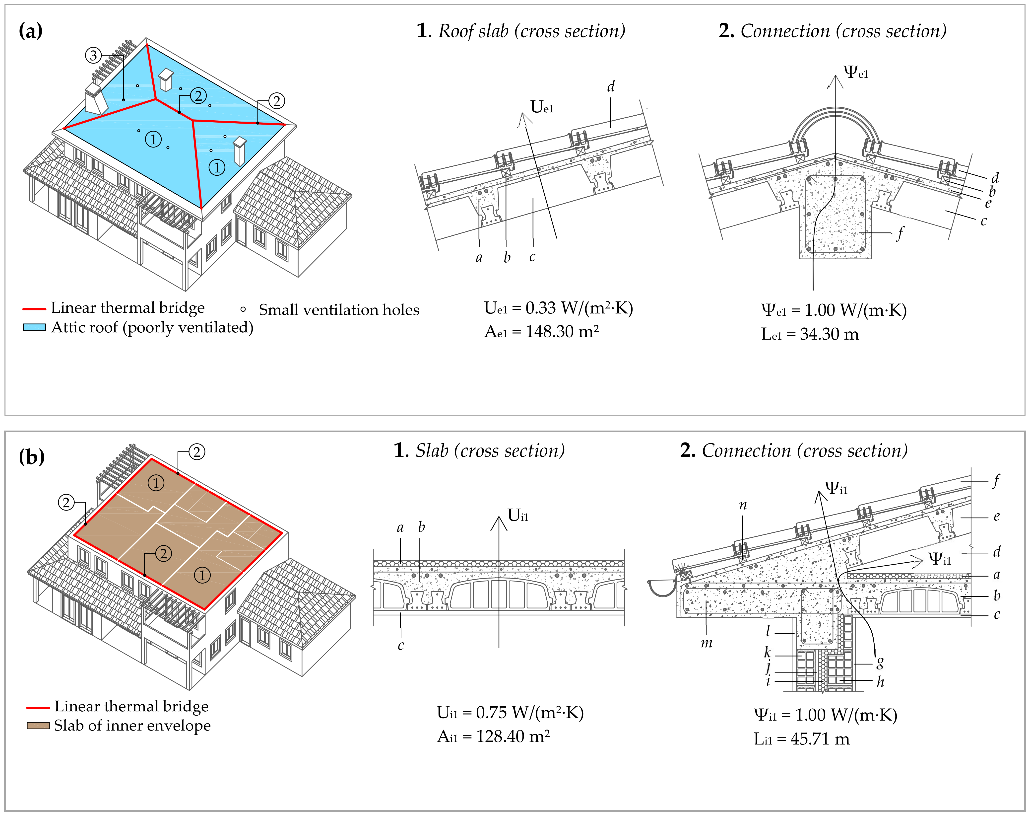
3.2. Case Study 2
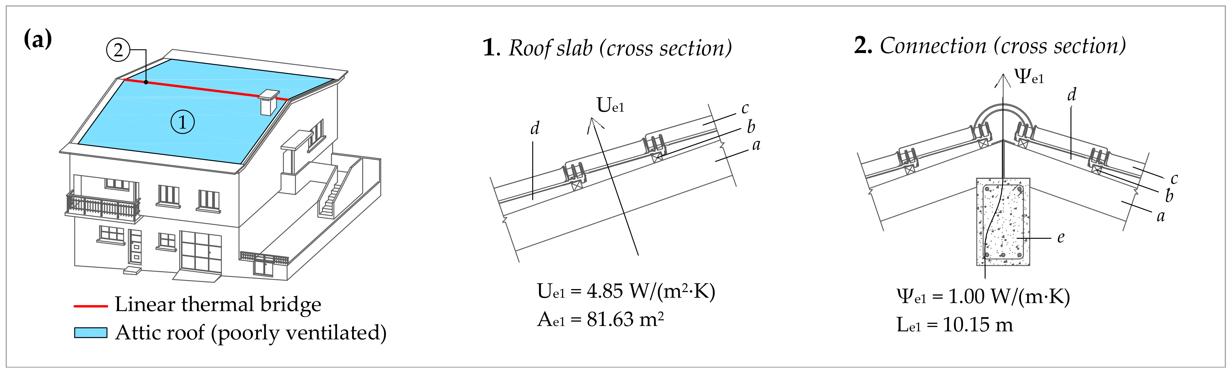
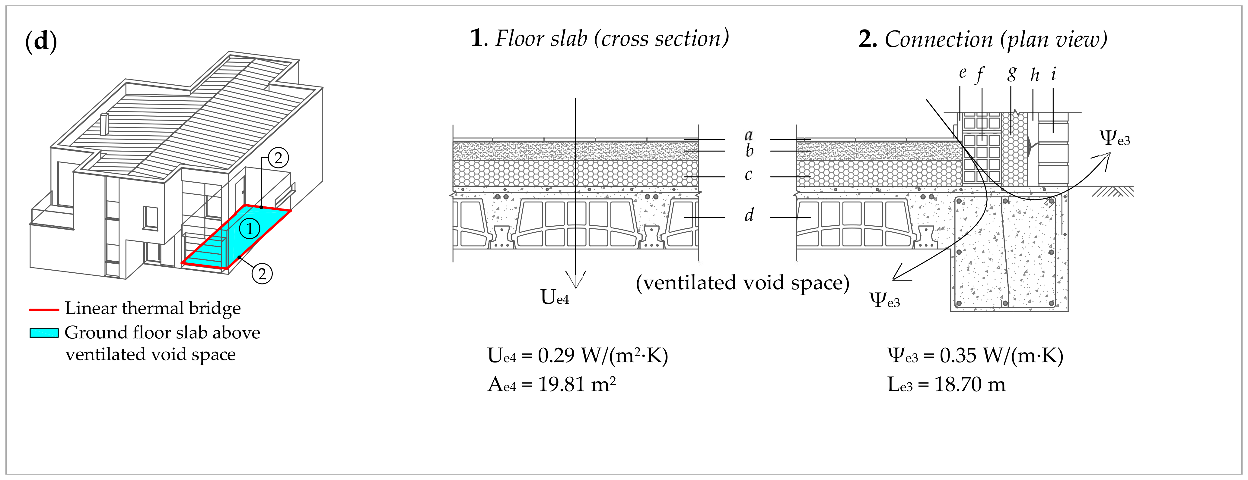
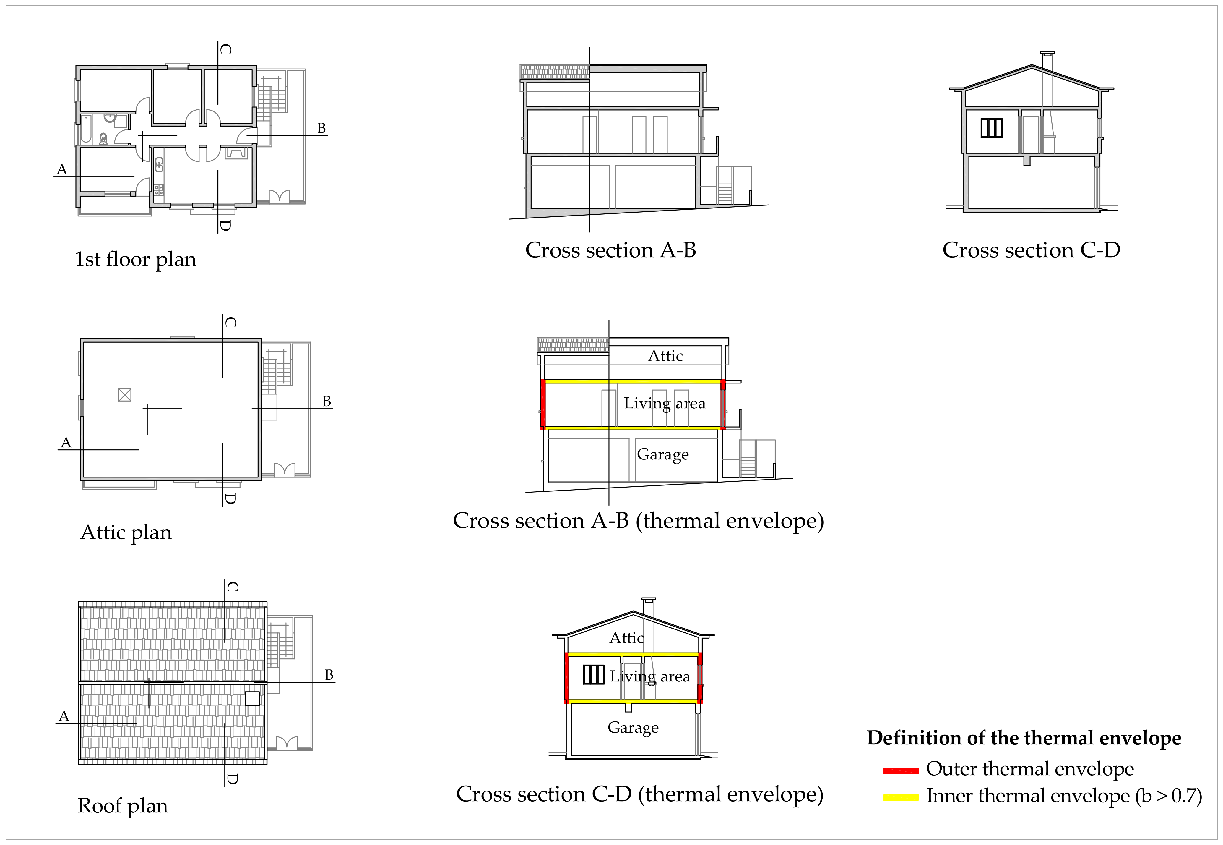
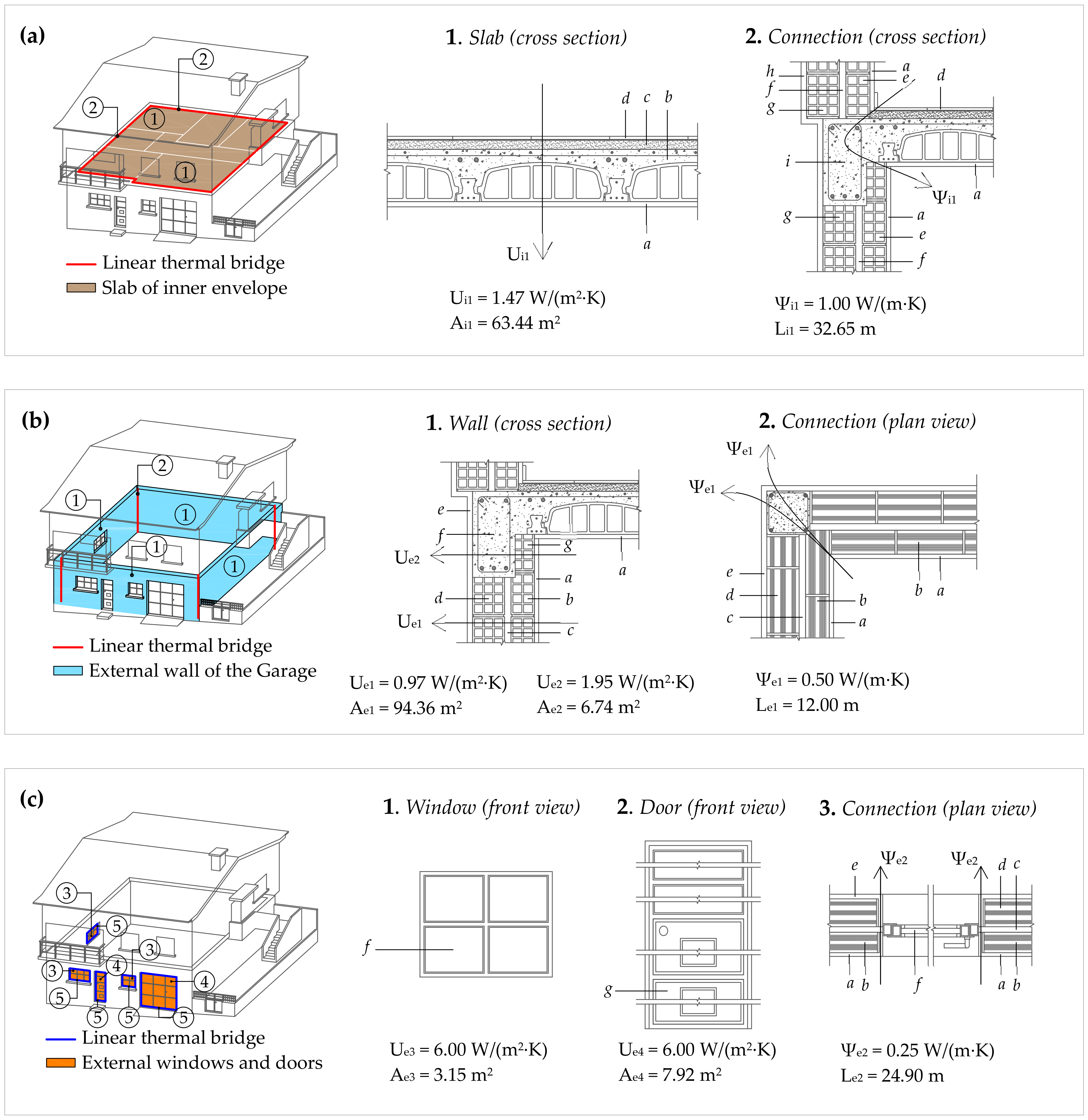
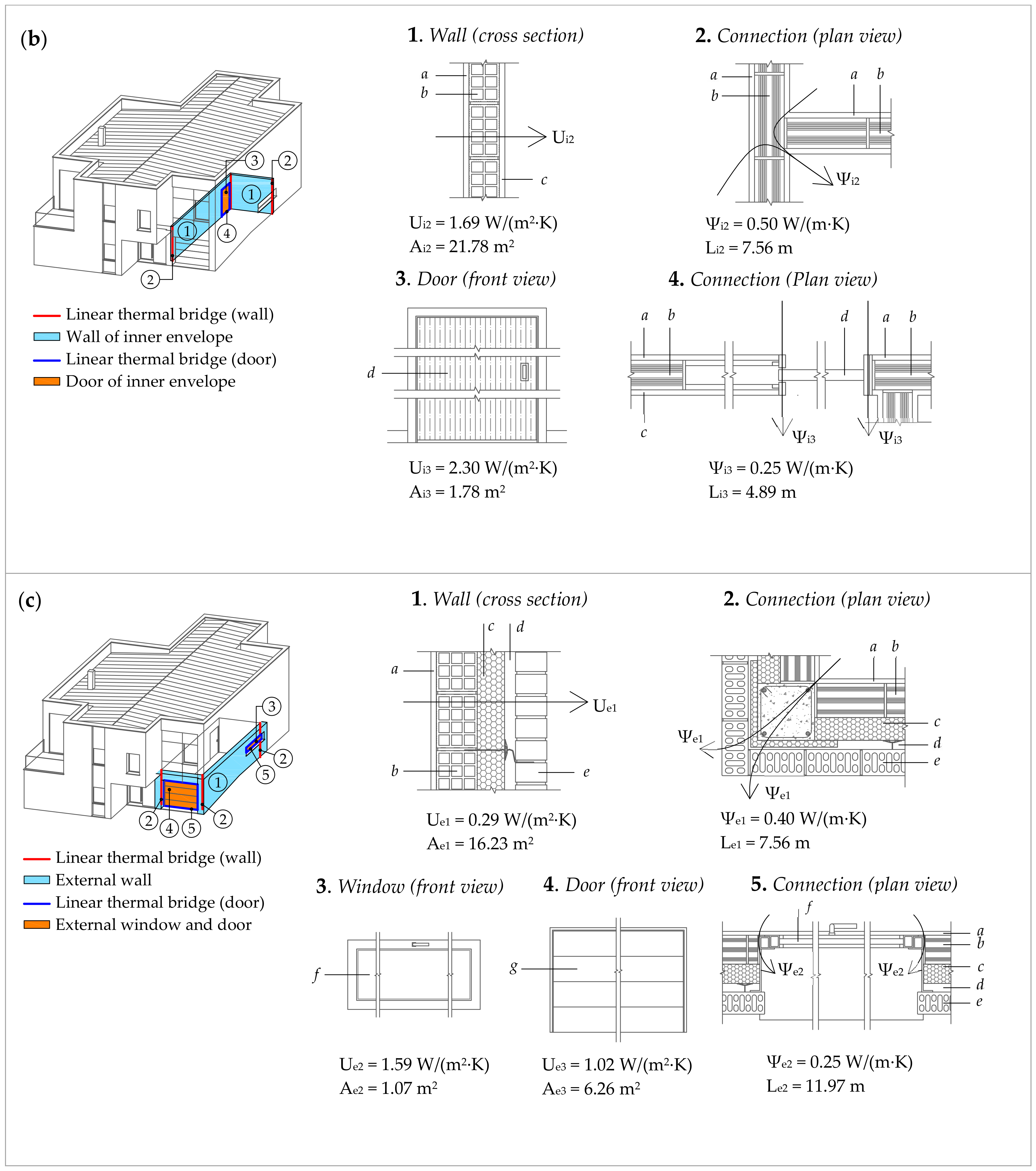
3.3. Case Study 3
4. Results
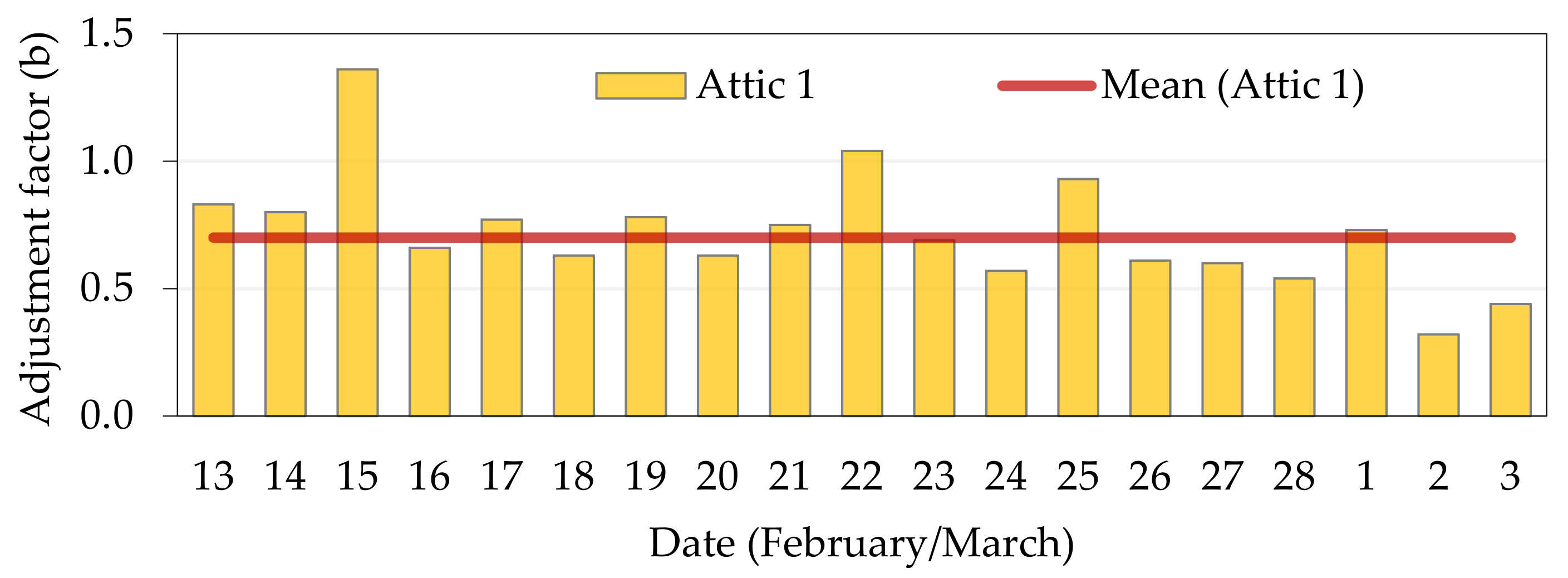
4.1. Case Study 1
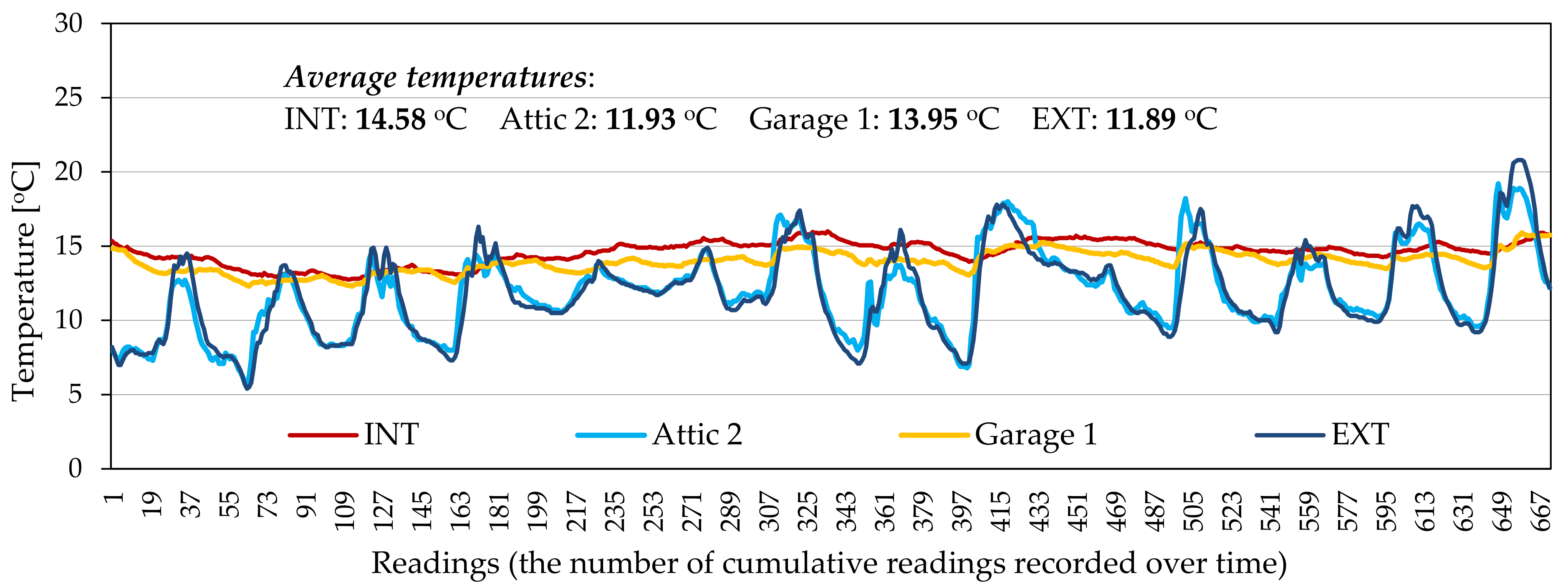
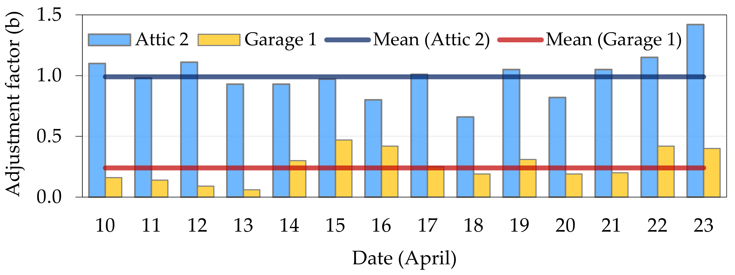
4.1.1. Measured Values
4.1.2. Simplified Methods
4.2. Case Study 2
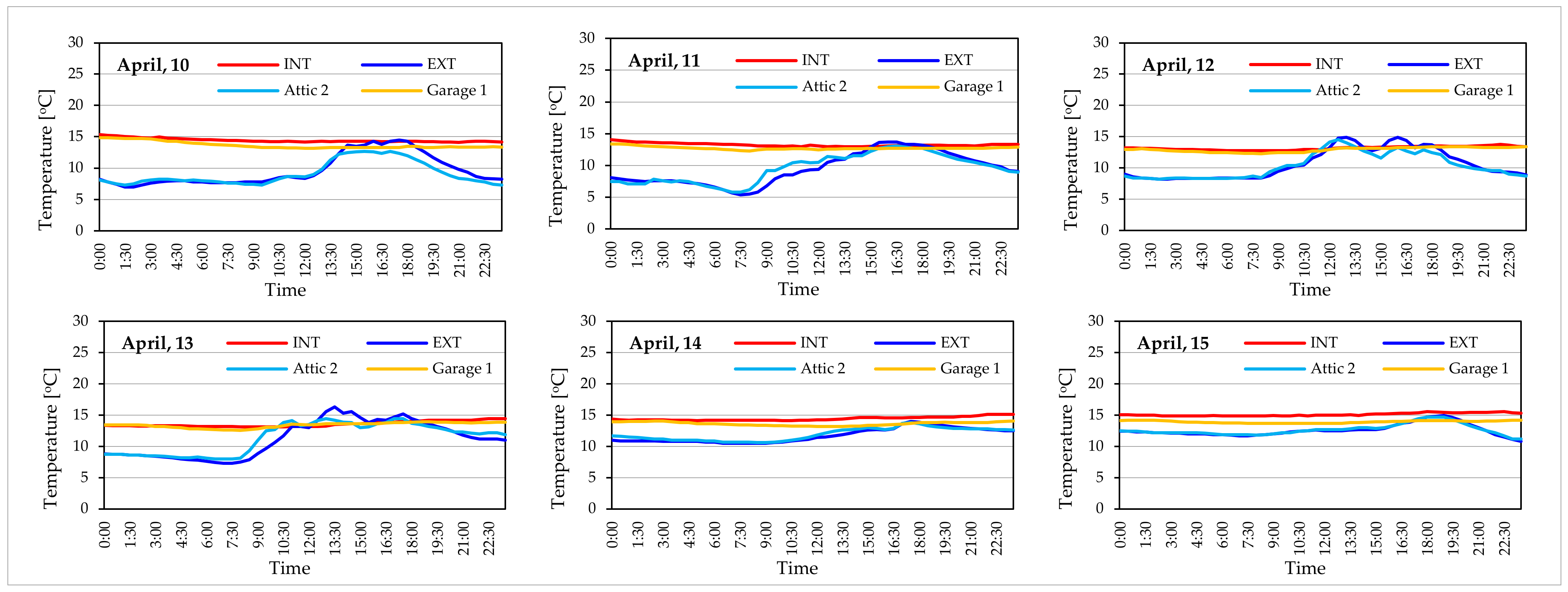
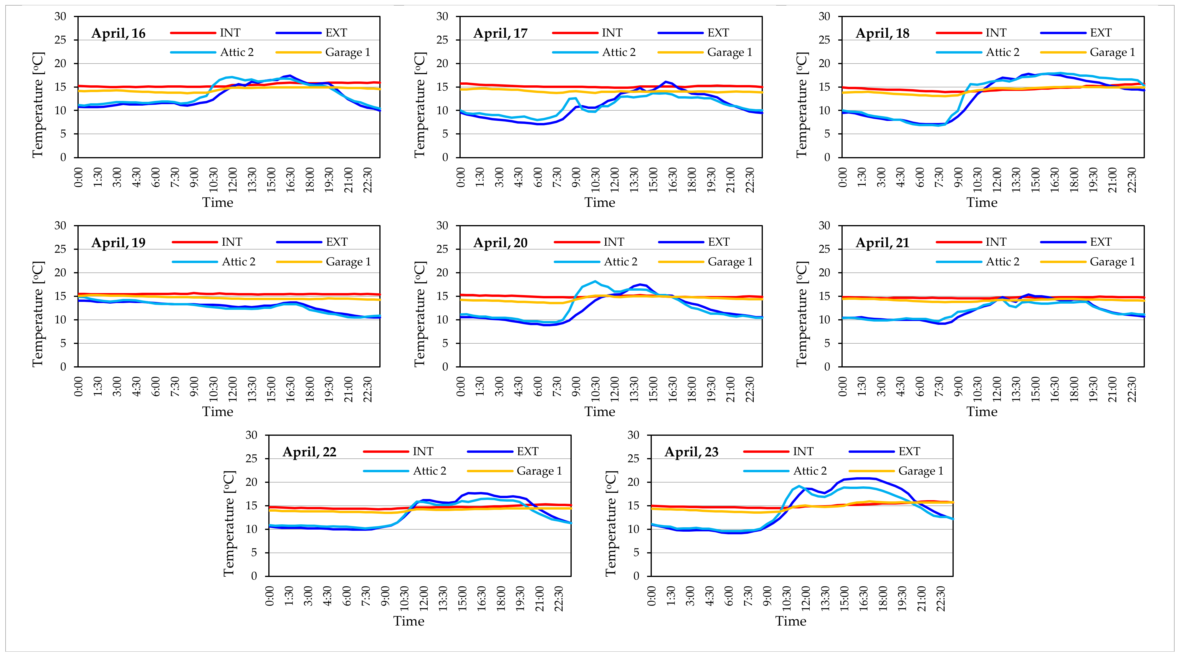
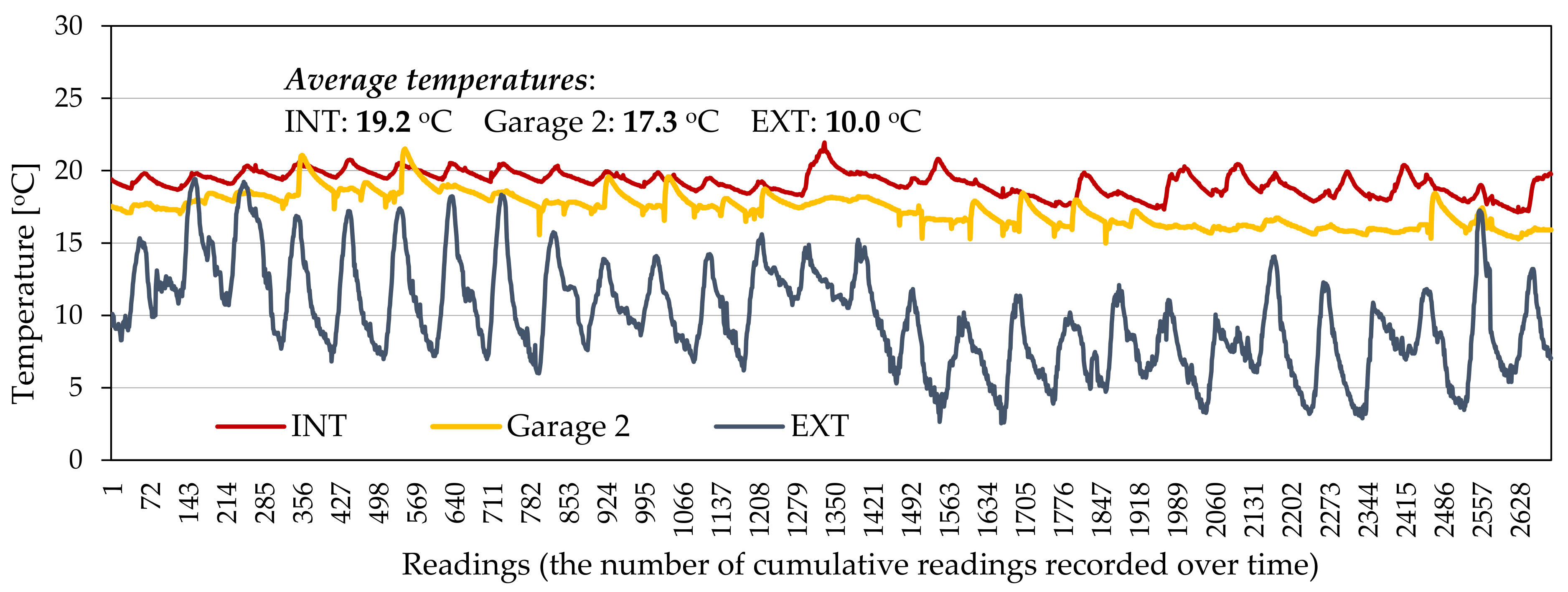
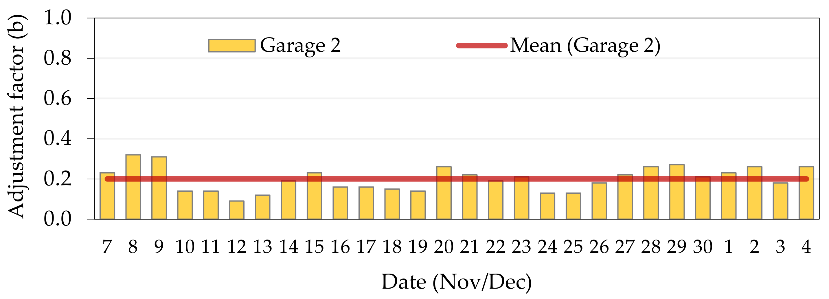
4.2.1. Measured Values
4.2.2. Simplified Methods
4.3. Case Study 3
4.3.1. Measured Values
4.3.2. Simplified Methods
5. Discussion
6. Conclusions
- (1)
- EN ISO 13789 and BR 443 have provided very similar values. It can be concluded that the consideration of linear thermal bridges does not have a very significant weight in determining the value of the adjustment factor (b).
- (2)
- If the purpose is to simplify the procedures of EN ISO 13789, the overall obtained results have shown that BR 443 is a very effective alternative, reducing the time spent on the calculation by not considering linear thermal bridges. In a second order of choice, the RE2020 proved to be very effective, with an even lower calculation effort than BR 443.
- (3)
- RE2020 was the most consistent on estimation of the on-site measured b-value. Even so, clarification is needed in the RE2020 method: 1) to better define what is considered an insulated or non-insulated partition; 2) to describe, in more detail, the different levels of ventilation, especially in garages;
- (4)
- DB-HE has a very similar structure to the RE2020 method, concerning the variables under consideration, but it fails by not considering the situation where both INT-UnSp and UnSp-EXT partitions are isolated and narrow the options of the Ai/Ae ratio.
- (5)
- REH/DEE also presents a similitude to RE2020 and DB-HE, however, by, being even more restrictive, not accounting for any insulated and non-insulated partitions, presenting an even more limited options for the Ai/Ae ratio and describing the ventilation rate in a very subjective manner.
- (6)
- RCCTE and REH/DEE significantly overestimate the adjustment factor values of the UnSp compared to the other analysed methods, except for strongly ventilated UnSp. These methods do not allow for the consideration of insulated or non-insulated partitions, conducting to the assumption of very conservative values, and overestimating transmission heat losses to UnSp. This can lead to less experienced designers to adopt less suitable constructive solutions for the building envelope, since in this particular case, the b-value will determine the minimum U-value requirement for the envelope partitions.
- (7)
- TGD-L is a simplification of BR 443 procedure, but it has shown to be less consistent than RE2020 in the estimation of the adjustment factor. It takes into account the U-value of the partition between INT and UnSp, as well as the thermal resistance conferred by UnSp. The thermal resistance of the UnSp, such as garages, conservatory-type sunroom, stairwells, and access corridors in flats are well-defined, but it is less clear when dealing with the attics.
- (8)
- The UNI/TS is for application in existent buildings and has very limited options if the purpose is for use in new buildings.
- (9)
- Uncertainty of the estimation of the hourly air renewal rate of the UnSp, by air exchange with outdoor air, has a significant impact on the accuracy of the analysed methods.
- (10)
- The thermal characteristics of the elements that separate the INT from UnSp and the UnSp from EXT are relevant for estimating the UnSp adjustment factor (b). Accounting only for the areas of the elements that separate the INT from UnSp and the UnSp from EXT results in a worse estimate of the adjustment factor (b).
- (11)
- The fact that the heat transfer coefficient through the garage floor was not accounted for in EN ISO 13789 and BR 443 does not seem to have affected the accuracy of the adjustment factor estimate.
- (12)
- For strongly ventilated UnSp, the existence of thermal insulation in the outer envelope of UnSp has no significant effect on the adjustment factor (b).
Author Contributions
Funding
Data Availability Statement
Acknowledgments
Conflicts of Interest
References
- Guterres, A. Secretary-General’s Statement on the Conclusion of the UN Climate Change Conference COP26 on 13 November 2021. Available online: https://www.un.org/sg/en/node/260645 (accessed on 3 December 2021).
- European Commission. Clean Energy for All Europeans; Publications Office of the European Union: Luxembourg, 2019. [Google Scholar] [CrossRef]
- International Energy Agency (IEA). Energy Performance Certification of Buildings—A Policy Tool to Improve Energy Efficiency. Available online: https://www.iea.org/publications/freepublications/publication/buildings_certification.pdf (accessed on 15 December 2021).
- Carlos, J.S.; Nepomuceno, M.C.S. A simple methodology to predict heating load at an early design stage of dwellings. Energy Build. 2012, 55, 198–207. [Google Scholar] [CrossRef]
- Ballarini, I.; Primo, E.; Corrado, V. On the Limits of the Quasi-Steady-State Method to Predict the Energy Performance of Low-Energy Buildings. Therm. Sci. 2018, 22 (Suppl. 4), S1117–S1127. [Google Scholar] [CrossRef] [Green Version]
- Directive 2010/31/EU, Energy Performance of Buildings (Recast EPBD). Off. J. Eur. Union 2010, L153, 13–35.
- Directive (EU) 2018/844, Amending Directive 2010/31/EU on the Energy Performance of Buildings and Directive 2012/27/EU on Energy Efficiency. Off. J. Eur. Union. 2018, L156, 75–91.
- EN ISO 13789:2017; Thermal performance of buildings—Transmission and ventilation heat transfer coefficients—Calculation method. CEN: Brussels, Belgium, 2017.
- Vučićević, B.S.; Jovanović, M.P.; Turanjanin, V.; Bakić, V.; Radivojević, D. Temperature correction factor simulation over the heating period. Therm. Sci. 2018, 22 (Suppl. 4), 1083–1093. [Google Scholar] [CrossRef]
- Anderson, B. Conventions for U-Value Calculations: Report BR 443 (2006 Edition); BRE Press: Berkshire, UK, 2006. [Google Scholar]
- Building Regulations, Technical Guidance Document L 2021, Conservation of Fuel and Energy—Dwellings; Government of Ireland: Dublin, Ireland, 2021.
- Decree-Law 80/2006 of de 4 de Abril; Regulamento das Características de Comportamento Térmico dos Edifícios (RCCTE) [Regulation of Thermal Behavior Characteristics of Buildings]; Ministério das Obras Públicas, Transportes e Comunicações: Lisbon, Portugal, 2006; (In Portuguese). Available online: https://files.dre.pt/1s/2006/04/067a00/24682513.pdf (accessed on 15 December 2021).
- Decree-Law 118/2013 Regulamento de Desempenho Energético dos Edifícios de Habitação (REH) [Regulation on the Energy Performance of Residential Buildings]; Ministério da Economia e do Emprego: Lisbon, Portugal, 2013; (In Portuguese). Available online: https://files.dre.pt/1s/2013/08/15900/0498805005.pdf (accessed on 15 December 2021).
- Manual SCE, Manual Técnico para a Avaliação do Desempenho Energético dos Edifícios (DEE:2021) [Technical Manual for the Assessment of Energy Performance of Buildings], v.1; Direção Geral de Energia e Geologia: Lisboa, Portugal, 2021. (In Portuguese)
- DB-HE, Documento Básico HE, Ahorro de Energía [Basic Document HE, Energy Saving]; Ministerio de Fomento: Madrid, Spain, 20 December 2019. (In Spanish)
- Méthodes et Procédures Applicables au Diagnostic de Performance Energétique et aux Logiciels l’Etablissant. Available online: https://www.legifrance.gouv.fr/jorf/id/JORFTEXT000043353381 (accessed on 3 December 2021).
- UNI/TS 11300-1:2014; Prestazioni Energetiche Degli Edifice—Parte 1: Determinazione del Fabbisogno di Energia Termica Dell’edificio per la Climatizzazione Estiva ed Invernale [Energy Performance of Buildings—Part 1: Determination of the Thermal Energy Needs of Buildings for Heating and Cooling]; Ente Nazionale Italiano di Unificazione (UNI): Milano, Italy, 2014. (In Italian)
- S.I. No. 183/2019 (Statutory Instruments), European Union (Energy Performance of Buildings) Regulations 2019. Available online: https://www.irishstatutebook.ie/eli/2019/si/183/made/en/print (accessed on 3 December 2021).
- EN ISO 6946:2017; Building components and building elements—Thermal resistance and thermal transmittance—Calculation methods. CEN: Brussels, Belgium, 2017.
- Directive 2002/91/EC, Energy Performance of Buildings (EPBD). Off. J. Eur. Communities 2003, L 1, 65–71.
- Directive 2012/27/EU, Energy efficiency, amending Directives 2009/125/EC and 2010/30/EU and repealing Directives 2004/8/EC and 2006/32/EC. Off. J. Eur. Union 2012, L 315, 1–56.
- Directive (EU) 2019/944 Common Rules for the Internal Market for Electricity and Amending Directive 2012/27/EU (Recast). Off. J. Eur. Union 2019, L 158, 125–199.
- Decree-Law 101-D/2020 Desempenho Energético de Edifícios e Sistema de Certificação Energética (SCE) [Energy Performance of Buildings and Energy Certification System]. Available online: https://files.dre.pt/1s/2020/12/23701/0002100045.pdf (accessed on 15 December 2021).
- Decree-Law 102/2021 Requisitos de Acesso e de Exercício da Atividade dos Técnicos do Sistema de Certificação Energética dos Edifícios (SCE) [Requirements for Access and Exercise of the Activity of Technicians of the Energy Certification System for Buildings]. Available online: https://files.dre.pt/1s/2021/11/22500/0000600015.pdf (accessed on 3 December 2021).
- Real Decreto 732/2019 Modifica el Código Técnico de la Edificación (CTE) [Amends the Technical Building Code; Ministerio de Fomento: Madrid, Spain, 2019. (In Spanish)
- DA_DB-HE1; Documento de Apoyo al Documento Básico, DB-HE Ahorro de Energia, Sección HE1, Condiciones Para el Control de la Demanda Energética, Código Técnico de la Edificación [Support Document to Basic Document DB-HE Energy Saving, Section HE1, Con-ditions to Control the Energy Demand, Technical Building Code].; Ministerio de Transporte, Movilidad y Agenda Urbana: Madrid, Spain, 2020. (In Spanish)
- Decree 2021-1004 Exigences de Performance énergétique et Environnementale des Constructions de Bâtiments en France Métropolitaine (RE2020) [Energy and Environmental Performance Requirements of Building Constructions in Mainland France]. Available online: https://www.legifrance.gouv.fr/jorf/id/JORFTEXT000043877196 (accessed on 3 December 2021).
- Decree No. 48 of 10 June 2020 ; Attuazione Della Direttiva (UE) 2018/844 del Parlamento Europeo e del Consiglio, del 30 Maggio 2018, Che Modifica la Direttiva 2010/31/UE Sulla Prestazione Energetica Nell’edilizia e la Direttiva 2012/27/UE Sull’Efficienza Energetica [Im-plementation of Directive (EU) 2018/844 Amending Directive 2010/31/EU on the Energy Performance of Buildings and Directive 2012/27/EU on Energy Efficiency]; European Union: Brussels, Belgium, 2020.
- EN ISO 14683:2017; Thermal bridges in building construction—Linear thermal transmittance—Simplified methods and default values. CEN: Brussels, Belgium, 2017.
- EN ISO 10211:2017; Thermal bridges in building construction—Heat flows and surface temperatures—Detailed calculations. CEN: Brussels, Belgium, 2017.
- EN ISO 13370:2017; Thermal performance of buildings—Heat transfer via the ground—Calculation method. CEN: Brussels, Belgium, 2017.


| Airtightness Type | ne (h−1) | Example of Unheated Space |
|---|---|---|
| No doors or windows, all joints between components well-sealed, no ventilation openings provided. | 0.1 | Internal Space with no external elements and no ventilation. |
| All joints between components well-sealed, no ventilation openings provided. | 0.5 | Space with external elements, windows, and doors, but well-sealed and no ventilation openings. |
| All joints well-sealed, small openings provided for ventilation. | 1.0 | Space with external elements but well-sealed and passive duct with controllable louvers between space and outside. |
| Not airtight, due to some localised open joints or permanent ventilation openings. | 3.0 | Space with external elements and wall fan with permanent opening. |
| Not airtight, due to numerous open joints, or large or numerous permanent ventilation openings. | 10.0 | Carpark with a number of permanent ventilation openings. |
| Value of U0 (W/(m2·K)) | |
|---|---|
| <1 | The adjustment is not made if ≤10% |
| 1 to 3 | The adjustment is not made if ≤5% |
| >3 | The adjustment is always done |
| (*) It can also be expressed by: | |
| UnSp | Element between the Garage and the Dwelling | Typical Resistance (Ru) | |
|---|---|---|---|
| Outside 1 | Inside 2 | ||
 | Side wall, end wall and floor | 0.33 | 0.68 |
 | One wall and floor | 0.25 | 0.54 |
 | Side wall, end wall and floor | 0.26 | 0.56 |
 | One wall | 0.09 | --- |
| Number of Walls between Dwelling and Conservatory/Sunroom | Typical Resistance (Ru) |
|---|---|
| One | 0.06 |
| Two (conservatory in angle of dwelling) | 0.14 |
| Three (conservatory in recess) | 0.25 |
| Type of Unheated Space (UnSp) | Typical Resistance (Ru) |
|---|---|
| Stairwells: —Facing wall exposed | 0.82 |
| —Facing wall not exposed | 0.90 |
| Access corridors: —Facing wall exposed, corridor above or below | 0.31 |
| —Facing wall exposed, corridor above and below | 0.28 |
| —Facing wall not exposed, corridor above or below | 0.43 |
| —Facing wall not exposed, corridor above and below | 0.40 |
| Type of Unheated Space | Ai/Ae | ||
|---|---|---|---|
| <1 | 1 to 10 | >10 | |
| 1- Common circulation spaces: | |||
| 1.1- With no direct opening to the outside | 0.6 | 0.3 | 0 |
| 1.2- With a permanet opening to the outside (1) | |||
| (a) Permanent openings area/total volume < 0.05 m2/m3 | 0.8 | 0.5 | 0.1 |
| (b) Permanent openings area/total volume ≥ 0.05 m2/m3 | 0.9 | 0.7 | 0.3 |
| 2- Commercial spaces | 0.8 | 0.6 | 0.2 |
| 3- Adjacent buildings | 0.6 | 0.6 | 0.6 |
| 4- Warehouses | 0.95 | 0.7 | 0.3 |
| 5- Garages: | |||
| 5.1- Private | 0.8 | 0.5 | 0.3 |
| 5.2- Collective | 0.9 | 0.7 | 0.4 |
| 5.3- Public | 0.95 | 0.8 | 0.5 |
| 6- Balconies, marquees and similar spaces | 0.8 | 0.6 | 0.2 |
| 7- Uninhabitated attic (accessible or not): | |||
| 7.1- Unventilated: ventilation openings area/attic area is less or equal than 500 mm2/m2 | 0.8 | 0.6 | 0.4 |
| 7.2- Poorly ventilated: ventilation openings area/attic area is higher than 500 and less or equal than 1500 mm2/m2 | 0.9 | 0.7 | 0.5 |
| 7.3- Strongly ventilated: ventilation openings area/attic area is greater than 1500 mm2/m2 | 1 | 1 | 1 |
| Ai/Ae | Vu ≤ 50 m3 | 50 m3 < Vu ≤ 200 m3 | Vu > 200 m3 | |||
|---|---|---|---|---|---|---|
| f | F | f | F | f | F | |
| Ai/Ae < 0.5 | 1.0 | 1.0 | 1.0 | 1.0 | 1.0 | 1.0 |
| 0.5 ≤ Ai/Ae < 1 | 0.7 | 0.9 | 0.8 | 1.0 | 0.9 | 1.0 |
| 1 ≤ Ai/Ae < 2 | 0.6 | 0.8 | 0.7 | 0.9 | 0.8 | 1.0 |
| 2 ≤ Ai/Ae < 4 | 0.4 | 0.7 | 0.5 | 0.9 | 0.6 | 0.9 |
| Ai/Ae ≥ 4 | 0.3 | 0.5 | 0.4 | 0.8 | 0.4 | 0.8 |
| Ai /Ae | Thermal Insulation Condition of the Partition between the INT and UnSp and the UnSp and EXT | |||||
|---|---|---|---|---|---|---|
| INT to UnSp (Insulated) and UnSp to EXT (Not Insulated) | INT to UnSp (Not Insulated) and UnSp to EXT (Not Insulated) | INT to UnSp (Not Insulated) and UnSp to EXT (Insulated) | ||||
| Case 1 | Case 2 | Case 1 | Case 2 | Case 1 | Case 2 | |
| Ai/Ae < 0.25 | 0.99 | 1.00 | 0.94 | 0.97 | 0.91 | 0.96 |
| 0.25 ≤ Ai/Ae ≤ 0.50 | 0.97 | 0.99 | 0.85 | 0.92 | 0.77 | 0.90 |
| 0.50 < Ai/Ae ≤ 0.75 | 0.96 | 0.98 | 0.77 | 0.87 | 0.67 | 0.84 |
| 0.75 < Ai/Ae ≤ 1.00 | 0.94 | 0.97 | 0.70 | 0.83 | 0.59 | 0.79 |
| 1.00 < Ai/Ae ≤ 1.25 | 0.92 | 0.96 | 0.65 | 0.79 | 0.53 | 0.74 |
| 1.25 < Ai/Ae ≤ 2.00 | 0.89 | 0.95 | 0.56 | 0.73 | 0.44 | 0.67 |
| 2.00 < Ai/Ae ≤ 2.50 | 0.86 | 0.93 | 0.48 | 0.66 | 0.36 | 0.59 |
| 2.50 < Ai/Ae ≤ 3.00 | 0.83 | 0.91 | 0.43 | 0.61 | 0.32 | 0.54 |
| Ai/Ae > 3 | 0.81 | 0.90 | 0.39 | 0.57 | 0.28 | 0.50 |
| Airtightness Level | ne (h−1) |
|---|---|
| 1. No doors, windows, or ventilation openings | 0.0 |
| 2. All components sealed, without ventilation openings | 0.5 |
| 3. All components well-sealed, small ventilation openings | 1.0 |
| 4. Poorly sealed, due to open joints or the presence of permanent ventilation openings | 5.0 |
| 5. Poorly sealed, numerous open joints, as well as large or numerous permanent ventilation openings | 10.0 |
| (a) INT to UnSp: Insulated; UnSp to EXT: Not Insulated | (b) INT to UnSp: Not Insulated; UnSp to EXT: Not Insulated | ||||||||||||
|---|---|---|---|---|---|---|---|---|---|---|---|---|---|
| Ai/Ae | Equivalent area coefficient UV,ue (Table 11) | Ai/Ae | Equivalent area coefficient UV,ue (Table 11) | ||||||||||
| 0.00 | 0.30 | 1.50 | 3.00 | 7.00 | 9.00 | 0.00 | 0.30 | 1.50 | 3.00 | 7.00 | 9.00 | ||
| ≤0.25 | 0.95 | 0.95 | 1.00 | 1.00 | 1.00 | 1.00 | ≤0.25 | 0.80 | 0.85 | 0.85 | 0.90 | 0.95 | 0.95 |
| 0.25 < ≤ 0.50 | 0.95 | 0.95 | 0.95 | 0.95 | 1.00 | 1.00 | 0.25 < ≤ 0.50 | 0.65 | 0.75 | 0.75 | 0.80 | 0.85 | 0.90 |
| 0.50 < ≤ 0.75 | 0.90 | 0.95 | 0.95 | 0.95 | 0.95 | 1.00 | 0.50 < ≤ 0.75 | 0.55 | 0.65 | 0.70 | 0.75 | 0.80 | 0.85 |
| 0.75 < ≤ 1.00 | 0.85 | 0.90 | 0.90 | 0.95 | 0.95 | 0.95 | 0.75 < ≤ 1.00 | 0.50 | 0.55 | 0.60 | 0.70 | 0.75 | 0.80 |
| 1.00 < ≤ 1.25 | 0.85 | 0.90 | 0.90 | 0.90 | 0.95 | 0.95 | 1.00 < ≤ 1.25 | 0.45 | 0.50 | 0.55 | 0.65 | 0.70 | 0.80 |
| 1.25 < ≤ 2.00 | 0.80 | 0.80 | 0.85 | 0.90 | 0.90 | 0.95 | 1.25 < ≤ 2.00 | 0.35 | 0.40 | 0.45 | 0.50 | 0.60 | 0.70 |
| 2.00 < ≤ 2.50 | 0.75 | 0.80 | 0.80 | 0.85 | 0.90 | 0.90 | 2.00 < ≤ 2.50 | 0.30 | 0.35 | 0.40 | 0.45 | 0.55 | 0.65 |
| 2.50 < ≤ 3.00 | 0.70 | 0.75 | 0.80 | 0.85 | 0.90 | 0.90 | 2.50 < ≤ 3.00 | 0.25 | 0.30 | 0.35 | 0.40 | 0.50 | 0.60 |
| 3.00 < ≤ 3.50 | 0.65 | 0.75 | 0.75 | 0.80 | 0.85 | 0.90 | 3.00 < ≤ 3.50 | 0.20 | 0.30 | 0.30 | 0.40 | 0.50 | 0.55 |
| 3.50 < ≤ 4.00 | 0.65 | 0.70 | 0.75 | 0.80 | 0.85 | 0.90 | 3.50 < ≤ 4.00 | 0.20 | 0.25 | 0.30 | 0.35 | 0.45 | 0.50 |
| 4.00 < ≤ 6.00 | 0.55 | 0.60 | 0.65 | 0.70 | 0.80 | 0.85 | 4.00 < ≤ 6.00 | 0.15 | 0.20 | 0.20 | 0.25 | 0.35 | 0.40 |
| 6.00 < ≤ 8.00 | 0.45 | 0.55 | 0.60 | 0.65 | 0.75 | 0.80 | 6.00 < ≤ 8.00 | 0.10 | 0.15 | 0.15 | 0.20 | 0.30 | 0.35 |
| 8.00 < ≤ 10.0 | 0.40 | 0.50 | 0.50 | 0.60 | 0.70 | 0.75 | 8.00 < ≤ 10.0 | 0.10 | 0.10 | 0.15 | 0.20 | 0.25 | 0.30 |
| 10.0 < ≤ 25.0 | 0.35 | 0.40 | 0.45 | 0.50 | 0.60 | 0.70 | 10.0 < ≤ 25.0 | 0.05 | 0.10 | 0.10 | 0.15 | 0.20 | 0.25 |
| 25.0 < ≤ 50.0 | 0.20 | 0.25 | 0.30 | 0.35 | 0.45 | 0.50 | 25.0 < ≤ 50.0 | 0.05 | 0.05 | 0.05 | 0.05 | 0.10 | 0.15 |
| 50.0 < | 0.10 | 0.15 | 0.15 | 0.20 | 0.25 | 0.30 | 50.0 < | 0.00 | 0.00 | 0.00 | 0.05 | 0.05 | 0.05 |
| (c) INT to UnSp: not insulated; UnSp to EXT: insulated | (d) INT to UnSp: insulated; UnSp to EXT: insulated | ||||||||||||
| Ai/Ae | Equivalent area coefficient UV,ue (Table 11) | Ai/Ae | Equivalent area coefficient UV,ue (Table 11) | ||||||||||
| 0.00 | 0.30 | 1.50 | 3.00 | 7.00 | 9.00 | 0.00 | 0.30 | 1.50 | 3.00 | 7.00 | 9.00 | ||
| ≤0.25 | 0.35 | 0.50 | 0.60 | 0.65 | 0.75 | 0.85 | ≤0.25 | 0.80 | 0.90 | 0.90 | 0.95 | 0.95 | 0.95 |
| 0.25 < ≤ 0.50 | 0.20 | 0.35 | 0.45 | 0.50 | 0.60 | 0.70 | 0.25 < ≤ 0.50 | 0.65 | 0.80 | 0.85 | 0.85 | 0.90 | 0.95 |
| 0.50 < ≤ 0.75 | 0.15 | 0.25 | 0.35 | 0.40 | 0.50 | 0.65 | 0.50 < ≤ 0.75 | 0.55 | 0.70 | 0.75 | 0.80 | 0.85 | 0.90 |
| 0.75 < ≤ 1.00 | 0.15 | 0.20 | 0.25 | 0.35 | 0.40 | 0.55 | 0.75 < ≤ 1.00 | 0.50 | 0.65 | 0.70 | 0.75 | 0.85 | 0.90 |
| 1.00 < ≤ 1.25 | 0.10 | 0.15 | 0.25 | 0.30 | 0.35 | 0.50 | 1.00 < ≤ 1.25 | 0.45 | 0.60 | 0.65 | 0.75 | 0.80 | 0.90 |
| 1.25 < ≤ 2.00 | 0.05 | 0.10 | 0.15 | 0.20 | 0.25 | 0.40 | 1.25 < ≤ 2.00 | 0.35 | 0.45 | 0.55 | 0.65 | 0.70 | 0.80 |
| 2.00 < ≤ 2.50 | 0.05 | 0.10 | 0.15 | 0.15 | 0.20 | 0.35 | 2.00 < ≤ 2.50 | 0.30 | 0.40 | 0.50 | 0.55 | 0.65 | 0.80 |
| 2.50 < ≤ 3.00 | 0.05 | 0.10 | 0.10 | 0.15 | 0.20 | 0.30 | 2.50 < ≤ 3.00 | 0.25 | 0.35 | 0.45 | 0.55 | 0.60 | 0.75 |
| 3.00 < ≤ 3.50 | 0.05 | 0.05 | 0.10 | 0.10 | 0.15 | 0.25 | 3.00 < ≤ 3.50 | 0.20 | 0.35 | 0.40 | 0.50 | 0.60 | 0.70 |
| 3.50 < ≤ 4.00 | 0.05 | 0.05 | 0.10 | 0.10 | 0.15 | 0.25 | 3.50 < ≤ 4.00 | 0.20 | 0.30 | 0.40 | 0.45 | 0.55 | 0.70 |
| 4.00 < ≤ 6.00 | 0.00 | 0.05 | 0.05 | 0.05 | 0.10 | 0.20 | 4.00 < ≤ 6.00 | 0.15 | 0.25 | 0.30 | 0.35 | 0.45 | 0.60 |
| 6.00 < ≤ 8.00 | 0.00 | 0.05 | 0.05 | 0.05 | 0.10 | 0.15 | 6.00 < ≤ 8.00 | 0.10 | 0.20 | 0.25 | 0.30 | 0.40 | 0.55 |
| 8.00 < ≤ 10.0 | 0.00 | 0.05 | 0.05 | 0.05 | 0.05 | 0.10 | 8.00 < ≤ 10.0 | 0.10 | 0.15 | 0.20 | 0.25 | 0.35 | 0.45 |
| 10.0 < ≤ 25.0 | 0.00 | 0.00 | 0.05 | 0.05 | 0.05 | 0.10 | 10.0 < ≤ 25.0 | 0.05 | 0.10 | 0.15 | 0.20 | 0.25 | 0.40 |
| 25.0 < ≤ 50.0 | 0.00 | 0.00 | 0.00 | 0.00 | 0.00 | 0.05 | 25.0 < ≤ 50.0 | 0.05 | 0.05 | 0.10 | 0.10 | 0.15 | 0.25 |
| 50.0 < | 0.00 | 0.00 | 0.00 | 0.00 | 0.00 | 0.00 | 50.0 < | 0.00 | 0.05 | 0.05 | 0.05 | 0.05 | 0.10 |
| Typical Unheated Spaces in Dwellings | UV,ue |
|---|---|
| Garage, cellar, and veranda | 3 |
| Attic: —Strongly ventilated: Ao/Ac > 0.003 | 9 |
| —poorly ventilated: 0.0003 < Ao/Ac < 0.003 | 3 |
| —very poorly ventilated: Ao/Ac < 0.0003 | 0.3 |
| Unheated Space (UnSp) | b |
|---|---|
| Unheated Space with an external wall | 0.4 |
| Unheated Space without external windows and doors and with at least two external walls | 0.5 |
| Unheated Space with external doors and windows and at least two external walls (e.g., garages) | 0.6 |
| Unheated Space with three external walls (e.g., external stairwells) | 0.8 |
| Cellar or semi-basement without windows or external frames | 0.5 |
| Cellar or semi-basement with external windows or door frames | 0.8 |
| Attic with high ventilation rate without felt or board cladding (e.g., discontinuous covering materials) | 1.0 |
| Attic with non-insulated roof of other type | 0.9 |
| Attic with insulated roof | 0.7 |
| Internal circulation areas without external walls and with an air exchange rate lower than 0.5 h−1 | 0.0 |
| Freely ventilated interior circulation areas (ratio of opening area to room volume greater than 0.005 m²/m³) | 1.0 |
| Volume | Vent * | Elements That Separate INT from UnSp | Elements That Separate UnSp from EXT | ||||||
|---|---|---|---|---|---|---|---|---|---|
| Vu | ne | Ui1 | Ai1 | Ψi1 | Li1 | Ue1 | Ae1 | Ψe1 | Le1 |
| m3 | h−1 | W/(m2·K) | m2 | W/(m·K) | m | W/(m2·K) | m2 | W/(m·K) | m |
| 79.32 | 0.50 | 0.75 | 128.40 | 1.00 | 45.71 | 0.33 | 148.30 | 1.00 | 34.30 |
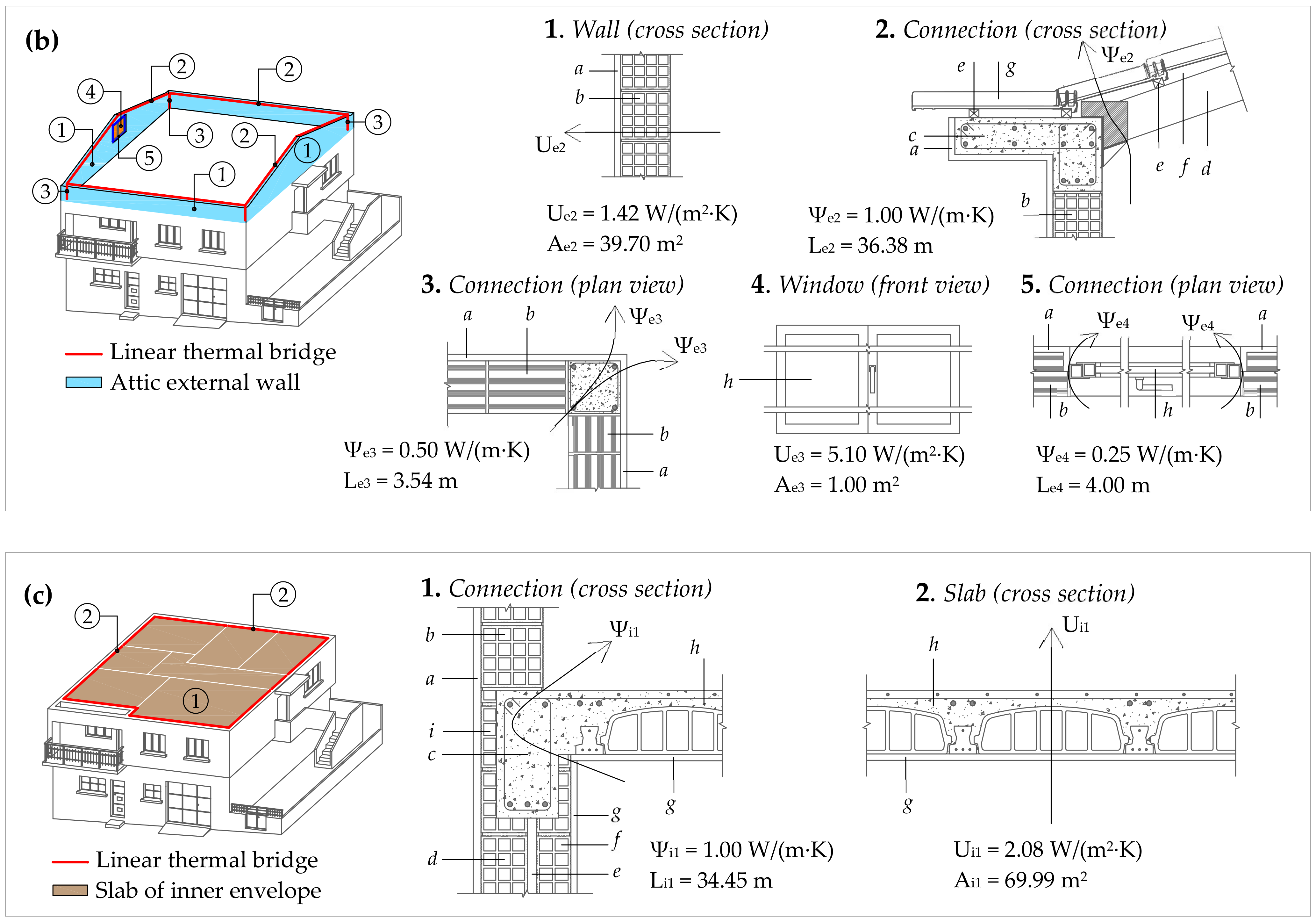
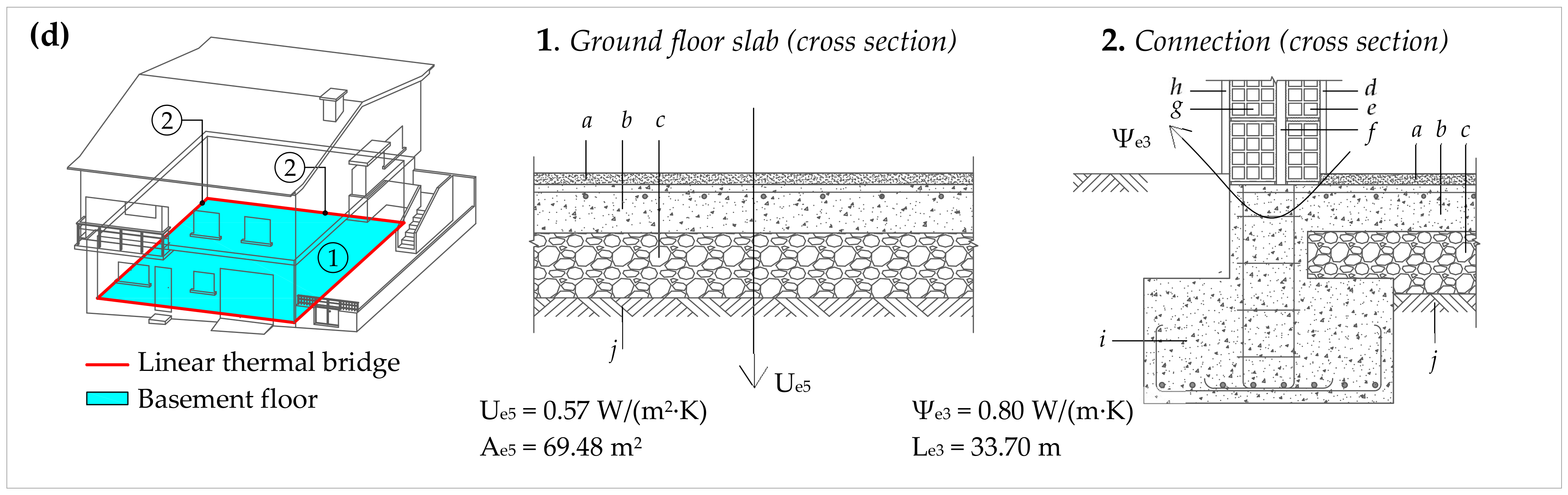
| Volume | Vent | Elements that Separate INT from UnSp | |||||||||||
|---|---|---|---|---|---|---|---|---|---|---|---|---|---|
| Vu | ne | Ui1 | Ai1 | Ψi1 | Li1 | ||||||||
| m3 | h−1 | W/(m2·K) | m2 | W/(m·K) | m | ||||||||
| 118.97 | 10.0 | 2.08 | 69.99 | 1.00 | 34.45 | ||||||||
| Elements that separate UnSp from EXT | |||||||||||||
| Ue1 | Ae1 | Ψe1 | Le1 | Ue2 | Ae2 | Ψe2 | Le2 | Ue3 | Ae3 | Ψe3 | Le3 | Ψe4 | Le4 |
| W/(m2·K) | m2 | W/(m·K) | m | W/(m2·K) | m2 | W/(m·K) | m | W/(m2·K) | m2 | W/(m·K) | m | W/(m·K) | m |
| 4.85 | 81.63 | 1.00 | 10.15 | 1.42 | 39.70 | 1.00 | 36.38 | 5.10 | 1.00 | 0.50 | 3.54 | 0.25 | 4.00 |
| Volume | Vent | Elements that Separate INT from UnSp | |||||||||
|---|---|---|---|---|---|---|---|---|---|---|---|
| Vu | ne | Ui1 | Ai1 | Ψi1 | Li1 | ||||||
| m3 | h−1 | W/(m2·K) | m2 | W/(m·K) | m | ||||||
| 208.44 | 0.50 | 1.47 | 63.44 | 1.00 | 32.65 | ||||||
| Elements that separate UnSp from EXT | |||||||||||
| Ue1 | Ae1 | Ψe1 | Le1 | Ue2 | Ae2 | Ψe2 | Le2 | Ue3 | Ae3 | Ue4 | Ae4 |
| W/(m2·K) | m2 | W/(m·K) | m | W/(m2·K) | m2 | W/(m·K) | m | W/(m2·K) | m2 | W/(m2·K) | m2 |
| 0.97 | 94.36 | 0.50 | 12.00 | 1.95 | 6.74 | 0.25 | 24.90 | 6.00 | 3.15 | 6.00 | 7.92 |
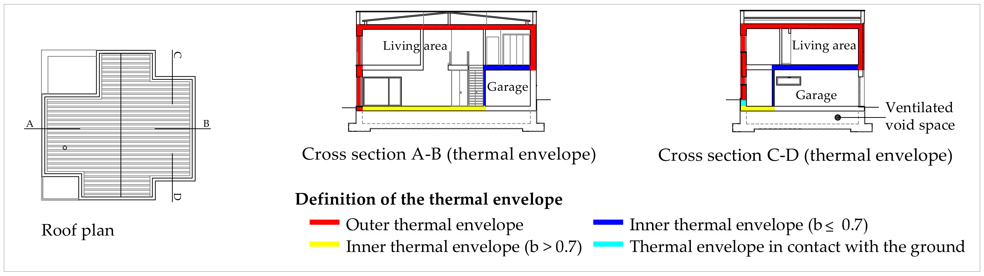
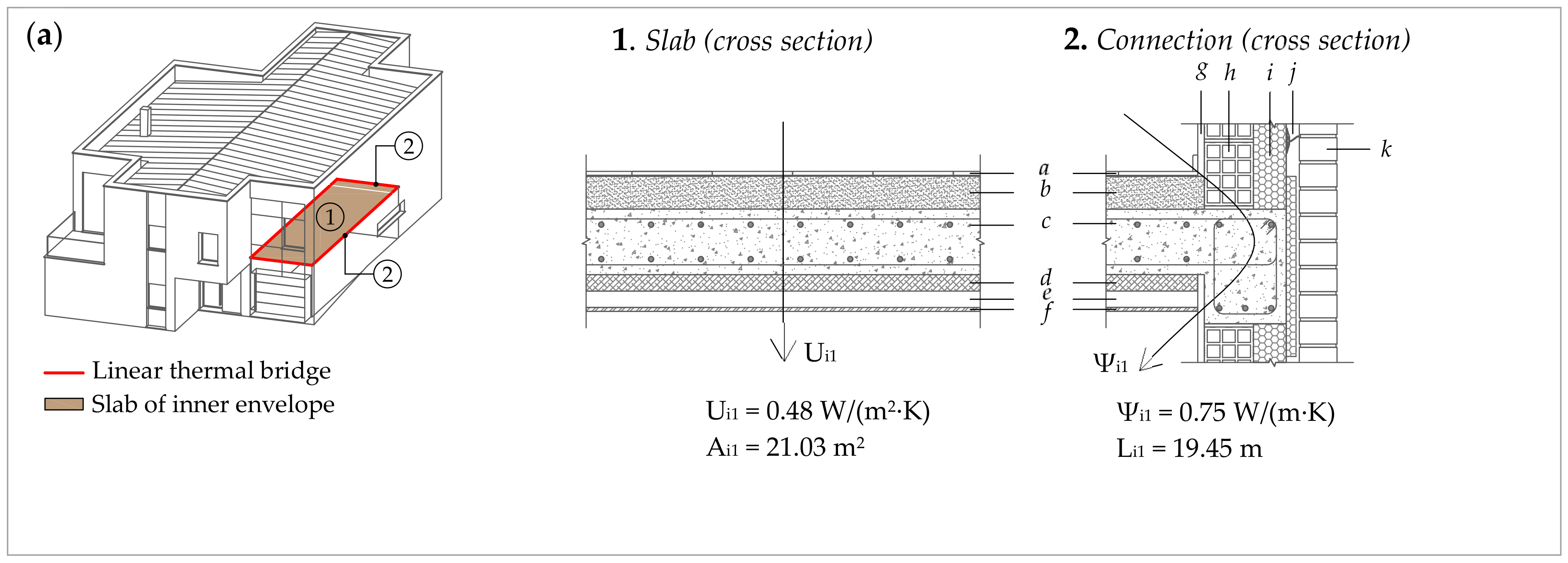
| Volume | Vent | Elements that Separate INT from UnSp | |||||||||||
|---|---|---|---|---|---|---|---|---|---|---|---|---|---|
| Vu | ne | Ui1 | Ai1 | Ψi1 | Li1 | Ui2 | Ai2 | Ψi2 | Li2 | Ui3 | Ai3 | Ψi3 | Li3 |
| m3 | h−1 | W/(m2·K) | m2 | W/(m·K) | m | W/(m2·K) | m2 | W/(m·K) | m | W/(m2·K) | m2 | W/(m·K) | m |
| 49.92 | 0.50 | 0.48 | 21.03 | 0.75 | 19.45 | 1.69 | 21.78 | 0.50 | 7.56 | 2.30 | 1.78 | 0.25 | 4.89 |
| Elements that separate UnSp from EXT | |||||||||||||
| Ue1 | Ae1 | Ψe1 | Le1 | Ue2 | Ae2 | Ψe2 | Le2 | Ue3 | Ae3 | ||||
| W/(m2·K) | m2 | W/(m·K) | m | W/(m2·K) | m2 | W/(m·K) | m | W/(m2·K) | m2 | ||||
| 0.29 | 16.23 | 0.40 | 7.56 | 1.59 | 1.07 | 0.25 | 11.97 | 1.02 | 6.26 | ||||
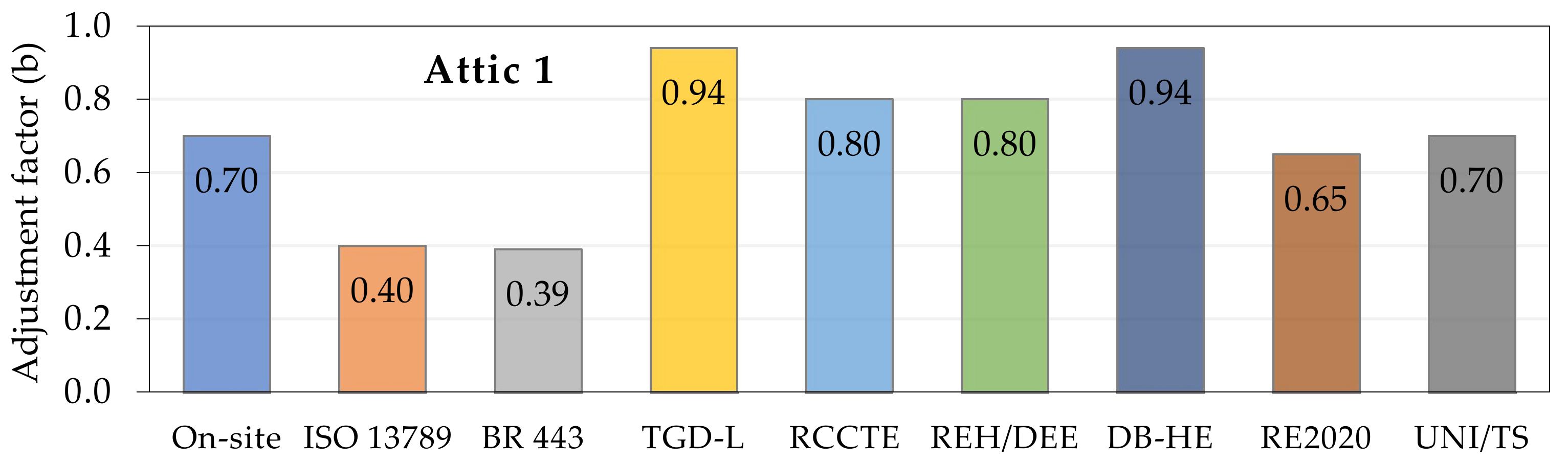
| Methodology | Formulas/Parameters | Source Data | b * |
|---|---|---|---|
| ISO 13789 | Hiu = ∑(Ui × Ai) + ∑(Ψi × Li) = 96.3 + 45.7 = 142.0 W/K | Table 13 | 0.40 |
| Hue = ∑(Ue × Ae) + ∑(Ψe × Le) + 0.33 × ne × Vu = 48.9 + 34.3 + 0.33 × 0.5 × 79.32 = 96.3 W/K | |||
| BR 443 | Hiu = ∑(Ui × Ai) = 96.3 W/K | Table 13 | 0.39 |
| Hue = ∑(Ue × Ae) + 0.33 × ne × Vu = 48.9 + 0.33 × 0.5 × 79.32 = 62.0 W/K | |||
| TGD-L | Table 3, Table 4 and Table 5: Typical Ru values of UnSp | Table 13 | 0.94 |
| Equation (25) (Uo = 0.75 W/(m2·K); Ru = 0.09 m2·K/W) | |||
| RCCTE | Table 6: Unventilated attic (open area of 320 cm2/128.4 m2 or 249 mm2/m2) | Table 13 | 0.80 |
| Ai = 128.4 m2; Ae = 148.3 m2; Ai/Ae = 0.87 | |||
| REH/DEE | Table 7: All components well-sealed, small ventilation openings (f) | Table 13 | 0.80 |
| Vu = 79.32 m3; Ai/Ae = 0.87 | |||
| DB-HE | Table 8 and Table 9: All components well-sealed, small ventilation openings (Case 1) | Table 13 | 0.94 |
| Ai/Ae = 0.87; INT to UnSp (insulated) and UnSp to EXT (insulated **) | |||
| RE2020 | Table 10d: Ai/Ae = 0.87; INT to UnSp (insulated) and UnSp to EXT (insulated) | Table 13 | 0.65 |
| Table 11: Small ventilation openings: Ao/Ac = 0.0320 m2/128.4 m2 = 0.00025 m2/m2 (Uv,ue = 0.3) | |||
| UNI/TS | Table 12: Attic with insulated roof | Table 13 | 0.70 |
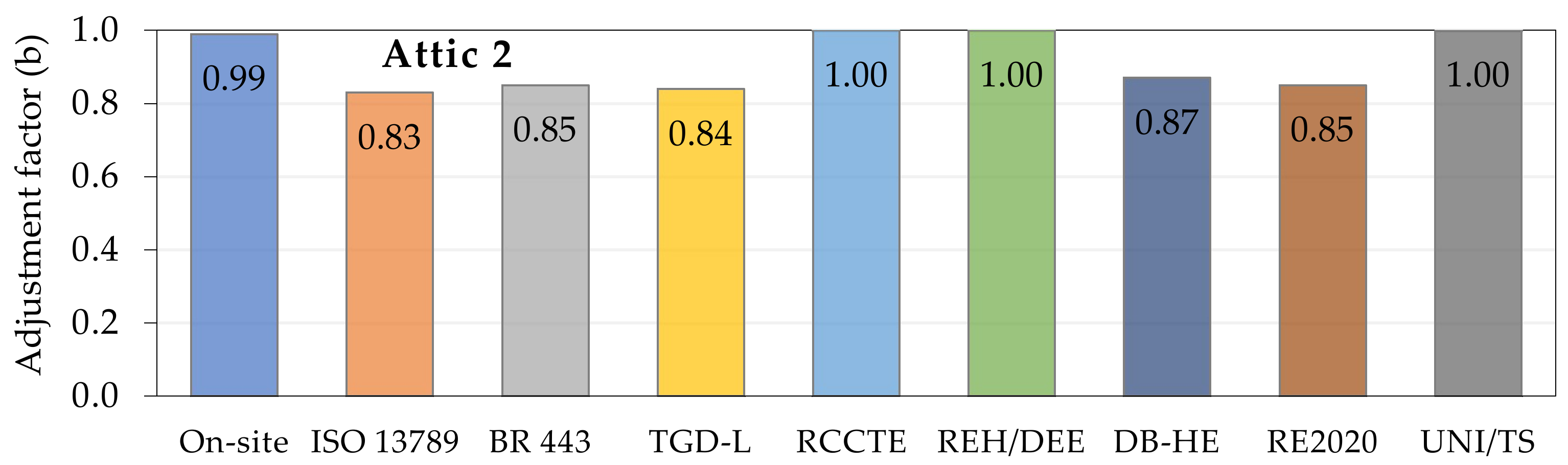
| Methodology | Formulas/Parameters | Source Data | b * |
|---|---|---|---|
| ISO 13789 | Hiu = ∑(Ui × Ai) + ∑(Ψi × Li) = 145.58 + 34.45 = 180.0 W/K | Table 14 | 0.83 |
| Hue = ∑(Ue × Ae) + ∑(Ψe × Le) + 0.33 × ne × Vu = 457.38 + 49.3 + 0.33 × 10 × 118.97 = 899.3 W/K | |||
| BR 443 | Hiu = ∑(Ui × Ai) = 145.6 W/K | Table 14 | 0.85 |
| Hue = ∑(Ue × Ae) + 0.33 × ne × Vu = 457.38 + 0.33 × 10 × 118.97 = 850.0 W/K | |||
| TGD-L | Table 3, Table 4 and Table 5: Ru = 0.09 m2·K/W; Uo = 2.08 W/(m2·K) | Table 14 | 0.84 |
| Equation (25) | |||
| RCCTE | Table 6: Strongly ventilated attic | Table 14 | 1.00 |
| Ai = 69.99 m2; Ae = 122.33 m2; Ai/Ae = 0.57 | |||
| REH/DEE | Table 7: Large or numerous permanent ventilation openings (F) | Table 14 | 1.00 |
| Vu = 118.97 m3; Ai/Ae = 0.57 | |||
| DB-HE | Table 8 and Table 9: Large or numerous permanent ventilation openings (Case 2) | Table 14 | 0.87 |
| Ai/Ae = 0.57; INT to UnSp (not insulated) and UnSp to EXT (not insulated) | |||
| RE2020 | Table 10b: Ai/Ae = 0.57; INT to UnSp (not insulated) and UnSp to EXT (not insulated) | Table 14 | 0.85 |
| Table 11: Strongly ventilated attic (Uv,ue = 9) | |||
| UNI/TS | Table 12: Attic with high ventilation rate without felt or board cladding | Table 14 | 1.00 |
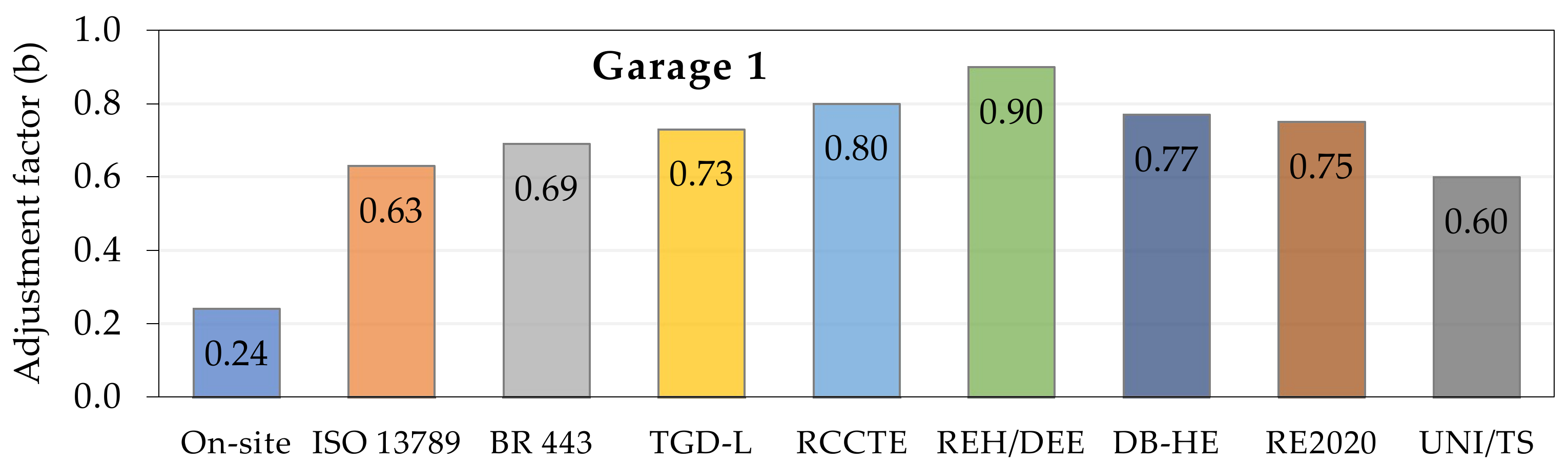
| Methodology | Formulas/Parameters | Source Data | b * |
|---|---|---|---|
| ISO 13789 | Hiu = ∑(Ui × Ai) + ∑(Ψi × Li) = 93.26 + 32.65 = 125.9 W/K | Table 15 | 0.63 |
| Hue = ∑(Ue × Ae) + ∑(Ψe × Le) + 0.33 × ne × Vu = 171.09 + 12.23 + 0.33 × 0.50 × 208.44 = 217.7 W/K | |||
| BR 443 | Hiu = ∑(Ui × Ai) = 93.3 W/K | Table 15 | 0.69 |
| Hue = ∑(Ue × Ae) + 0.33 × ne × Vu = 171.09 + 0.33 × 0.50 × 208.44 = 205.5 W/K | |||
| TGD-L | Table 3, Table 4 and Table 5: Ru = 0.25 m2·K/W; Uo = 1.47 W/(m2·K) | Table 15 | 0.73 |
| Equation (25) | |||
| RCCTE | Table 6: Private garage | Table 15 | 0.80 |
| Ai = 63.44 m2; Ae = 112.17 m2; Ai/Ae = 0.57 | |||
| REH/DEE | Table 7: All components sealed, without ventilation openings (f) | Table 15 | 0.90 |
| Vu = 208.44 m3; Ai/Ae = 0.57 | |||
| DB-HE | Table 8 and Table 9: All components sealed, without ventilation openings (Case 1) | Table 15 | 0.77 |
| Ai/Ae = 0.57; INT to UnSp (not insulated) and UnSp to EXT (not insulated) | |||
| RE2020 | Table 10b: Ai/Ae = 0.57; INT to UnSp (not insulated) and UnSp to EXT (not insulated) | Table 15 | 0.75 |
| Table 11: Garage (Uv,ue = 3) | |||
| UNI/TS | Table 12: Unheated Space with external doors and windows and at least two external walls | Table 15 | 0.60 |
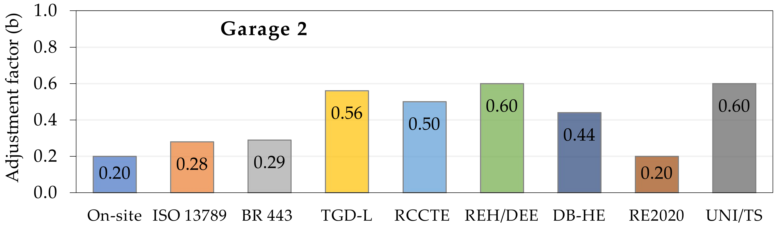
| Methodology | Formulas/Parameters | Source Data | b * |
|---|---|---|---|
| ISO 13789 | Hiu = ∑(Ui × Ai) + ∑(Ψi × Li) = 51.00 + 19.59 = 70.59 W/K | Table 16 | 0.28 |
| Hue = ∑(Ue × Ae) + ∑(Ψe × Le) + 0.33 × ne × Vu = 12.79 + 6.02 + 0.33 × 0.5 × 49.92 = 27.0 W/K | |||
| BR 443 | Hiu = ∑(Ui × Ai) = 51.0 W/K | Table 16 | 0.29 |
| Hue = ∑(Ue × Ae) + 0.33 × ne × Vu = 12.79 + 0.33 × 0.5 × 49.92 = 21.0 W/K | |||
| TGD-L | Table 3, Table 4 and Table 5: Ru = 0.68 m2·K/W; Uo = ∑(Ui × Ai)/∑(Ai) = 1.14 W/(m2·K) | Table 16 | 0.56 |
| Equation (25) | |||
| RCCTE | Table 6: Private garage | Table 16 | 0.50 |
| Ai = 44.59 m2; Ae = 23.56 m2; Ai/Ae = 1.89 | |||
| REH/DEE | Table 7: All components sealed, without ventilation openings (f) | Table 16 | 0.60 |
| Vu = 49.92 m3; Ai/Ae = 1.89 | |||
| DB-HE | Table 8 and Table 9: All components sealed, without ventilation openings (Case 1) | Table 16 | 0.44 |
| Ai/Ae = 1.89; INT to UnSp (not insulated) and UnSp to EXT (insulated) | |||
| RE2020 | Table 10c: Ai/Ae = 1.89; INT to UnSp (not insulated) and UnSp to EXT (insulated) | Table 16 | 0.20 |
| Table 11: Garage (Uv,ue = 3) | |||
| UNI/TS | Table 12: Unheated Space with external doors and windows and at least two external walls | Table 16 | 0.60 |
Publisher’s Note: MDPI stays neutral with regard to jurisdictional claims in published maps and institutional affiliations. |
© 2022 by the authors. Licensee MDPI, Basel, Switzerland. This article is an open access article distributed under the terms and conditions of the Creative Commons Attribution (CC BY) license (https://creativecommons.org/licenses/by/4.0/).
Share and Cite
Nepomuceno, M.C.S.; Martins, A.M.T.; Pinto, H.A.S. A Comparison between On-Site Measured and Estimated Based Adjustment Factor Values Used to Calculate Heat Losses to Unconditioned Spaces in Dwellings. Buildings 2022, 12, 146. https://doi.org/10.3390/buildings12020146
Nepomuceno MCS, Martins AMT, Pinto HAS. A Comparison between On-Site Measured and Estimated Based Adjustment Factor Values Used to Calculate Heat Losses to Unconditioned Spaces in Dwellings. Buildings. 2022; 12(2):146. https://doi.org/10.3390/buildings12020146
Chicago/Turabian StyleNepomuceno, Miguel C. S., Ana M. T. Martins, and Hugo A. S. Pinto. 2022. "A Comparison between On-Site Measured and Estimated Based Adjustment Factor Values Used to Calculate Heat Losses to Unconditioned Spaces in Dwellings" Buildings 12, no. 2: 146. https://doi.org/10.3390/buildings12020146
APA StyleNepomuceno, M. C. S., Martins, A. M. T., & Pinto, H. A. S. (2022). A Comparison between On-Site Measured and Estimated Based Adjustment Factor Values Used to Calculate Heat Losses to Unconditioned Spaces in Dwellings. Buildings, 12(2), 146. https://doi.org/10.3390/buildings12020146