Article

Similarity Law Study of Shaped Charges Penetrating a Concrete Target

1
Institute of Defense Engineering, AMS, PLA, Beijing 100850, China
2
College of Civil Engineering, Tongji University, Shanghai 200092, China
3
China Construction Engineering Bureau Co., Ltd., Shanghai 200122, China
*
Authors to whom correspondence should be addressed.
Buildings 2022, 12(12), 2268; https://doi.org/10.3390/buildings12122268
Submission received: 17 November 2022 / Revised: 30 November 2022 / Accepted: 7 December 2022 / Published: 19 December 2022
(This article belongs to the Special Issue Cement and Concrete Research)

Abstract

:
In order to study the similarity law of penetration of concrete targets by shaped charges, penetration tests of concrete targets with different sizes of shaped-charge jets were carried out, and the prototype and the model projectiles met the similarity law with a simulation ratio of 1:1.5. LS-DYNA finite element software was used to simulate the tests, and the accuracy of the ALE algorithm, fluid–solid coupling algorithm, material model, equation of state, and corresponding material parameters was verified. Numerical simulations were further conducted for the different types of shaped-charge jets (jets, rod jets, and explosively formed projectiles) formed by different liner angles penetrating into the concrete target, and the results show that the shaped-charge jets basically meet the similarity law when penetrating concrete targets.

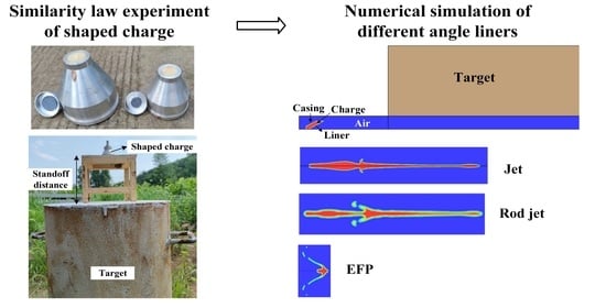
Graphical Abstract

1. Introduction

Shaped charge technology is widely used in tandem combatants and torpedoes against military targets [1,2], e.g., airport runways, underground bunkers, and ships, as well as civilian targets, e.g., industrial facilities for oil and gas extraction. For a variety of charge types, this paper focuses on the penetration effect of truncated conical charges of shaped charges on concrete-like materials.
As for the theoretical studies on shaped-charge penetration, Brikhoff et al. [3] proposed a constant velocity jet theory by simplifying the jet velocity and length to constants and assuming that the target is in a pure fluid state during the jet penetration of the target, which allows the strength of the target and metal jet to be neglected. Subsequently, Allison and Vitali [4] experimentally measured the existence of velocity gradients in the velocity direction of the shaped charge jet and proposed a nonuniform velocity jet theory based on the experimental results, which assumed that all jet microelements were emitted from a virtual source, and the velocity of microelements remained constant and linearly distributed. When the above models are utilized to calculate the jet penetration depth, the classical fluid dynamics formulas are adopted; i.e., the target strength is not considered. Tate [5] and Alekseevskii [6] studied the penetration effect of high-speed long rod projectiles regarding the high-speed long rod projectiles as fluid, with the strength effects of targets and projectiles under consideration at the same time, and proposed a hydrodynamic correction model, namely, the “A-T” model. There are different opinions on the effect of concrete strength on the depth of penetration by shaped-charge jets, though the concrete target strength has an obvious impact on the radial expansion of the jet; thus, the calculation of the concrete target resistance is directly related to the accuracy of the concrete target model for the penetration by shaped-charge jets. Tate [7] and Sternberg [8] considered that the target strength parameter is the cavity expansion pressure or target resistance under quasistatic conditions. Forrestal and Longcope [9] and Satapathy and Bless [10] used static spherical cavity expansion theory to solve the target resistance parameters of brittle materials, e.g., ceramic target materials. Based on the compressible model of jet penetration and combined with the Szendrei–Held expansion equation, Li and Chen [11] derived the expansion equation of the shaped-charge jet considering the compressibility of the bullet/target material. The model analysis showed that the jet radius, pressure at stagnation point, target strength, target density at stagnation point, and the shaped-charge jet velocity were the main factors affecting the jet reaming.
For experimental and numerical simulation studies, Murphy et al. [12,13] conducted experimental studies on the penetration of 20 MPa concrete, granite, and high-strength concrete with shaped charges and concluded that the jet energy was linearly related to the volume of the open pit and verified the equation of state (EOS) that can describe the porosity of granite. Huerta et al. [14] designed a 0.7 m diameter liner and conducted field tests on the penetration of tuff with shaped charges. Resnyansky and Weckert [15] conducted tests of shaped charges penetrating/perforating concrete target slabs, in which the shaped charges were divided into three structures with no, simple, or complex waveform adjusters, and the targets were divided into normal strength concrete (NSC, 40 MPa) and ultra-high-performance concrete (UHPC, 200 MPa). The results show that an effective waveform adjuster can significantly improve the performance of the shaped-charge jet; without a waveform adjuster, the depths of shaped charges penetrating into the two targets were 177 and 138 cm, respectively, with a reduction in depth of about 22%, which indicates that high-performance concrete has better performance compared with ordinary concrete. Wang et al. [16] conducted a systematic experimental study on the penetration of concrete with shaped charges and concluded that the penetration depth of shaped charges and the diameters of craters are quadratically related to the jet velocity. Elshenawy et al. [17] conducted an experimental study on the effect of perimeter pressure on jet penetration of concrete and introduced the target strength and perimeter pressure into the Allison–Vitalli equation, and the modified equation could predict the depth of jet penetration into the concrete target more accurately.
Ma et al. [18] carried out experiments on the penetration of shaped charges into a target in the presence of a magnetic field and found that the jet was easy to break and less stable at higher blast heights, while the magnetic field improved the stability of the jet and increased the depth of penetration of the shaped charge into a steel target. The depth of penetration by a 56 mm caliber shaped-charge structure increased by 77%, 72%, and 75% at blast heights of 490, 650, and 800 mm, respectively.
Zhang et al. [19] designed a new shaped-charge structure consisting of an internal copper liner and an external reactive liner, where the reactive liner was cold-pressed from polytetrafluoroethylene/aluminum powder. The tests showed that compared with the simple copper liner structure, the diameter of the crater and the spalling area of the new polytetrafluoroethylene charge structure penetrating the concrete target were increased to 2–4 times those of the original one. Moreover, as the reactive liner had an explosive effect, the new polytetrafluoroethylene charge structure could create a larger overpressure in the concrete-enclosed space.
Ma et al. [20] parametrically studied the formation of the shaped-charge jetby varying the number of detonation points, the length of the shell platform, the radius of the curvature, and the thickness of the liner in dynamics analysis software LS-DYNA. The relationship model between the parameters of jet formation and the structural parameters of the shaped charge was established, and the multi-objective optimal design of the shaped-charge structure could be carried out based on this model. Meanwhile, it was found that the velocity, aspect ratio, and kinetic energy of the shaped-charge jet were closely related to the structural parameters of the shaped charge, and the penetration performance of the optimized shaped charge was greatly improved.
Zhang et al. [21] studied the penetration characteristics of copper, iron, titanium, and aluminum material jets on high-strength concrete and carried out the simulation on the forming process of copper, iron, titanium, and aluminum material jets and the test of penetrating high-strength concrete targets. They found that the penetration depth of copper, iron, and titanium jets basically obeyed the density law; i.e., the penetration depth gradually decreased with decreasing density, and the penetration depth of aluminum jets was slightly greater than that of titanium jets; among them, the titanium jets had the largest jet diameter, crater volume, and the highest opening efficiency.
In the design of the product of the polygonal charge combatant, in order to shorten the development cycle of the new product, during the research, finalization, production and improvement of the new product, a reduced-scale model bomb can be designed first based on the tactical technical index requirements of the newly designed polygonal charge combatant; the model bomb can be used for model testing and improvement until satisfactory performance is obtained; and then the prototype bomb design can be carried out [3]. Huang and Chen [22] carried out tests of two EFPs satisfying similar conditions to penetrate a steel target with a simulation ratio of 1.33. According to the radiographs, the projectile shapes of the model and prototype projectiles were similar at relative moments, the head velocities and length-to-thin ratios were similar, and the penetration depths followed the simulation similarity law criterion. Tang and Bai [23] designed a prototype bullet with 60 mm caliber charge and a simulated bullet with 80 mm caliber charge. The conditions of the intrusion similarity law were satisfied by the prototype and the simulated bullet, and it was found that the intrusion depth of the simulated bullet and the prototype on the steel target satisfied the simulated ratio, i.e., the EFP intrusion similarity law was established. Li et al. [24] used a three-dimensional numerical simulation to simulate the process of penetration of a set of concentrated-energy jets into steel plates with a simulation ratio of 1.5, and the simulation results showed that the similarity law held. There is a lack of research on the similarity law for the penetration of concrete targets by shaped charges, mostly by means of numerical simulations and less by means of experiments.
In this paper, we carry out tests on the penetration of concrete targets with different sizes of shaped charges conforming to the similarity law and simulate the tests using LS-DYNA finite element (FE) software. By comparing the penetration depths of tests and numerical simulations, we verify the accuracy of the ALE algorithm, fluid–solid coupling algorithm, material model, EOS, and corresponding material parameters. Numerical simulations are further carried out for different types of shaped-charge intruders (jets, rod jets, and EFP) formed by different angles of the drug-type cover to intrude into the concrete target, and the similar laws of different types of shaped-charge intruders in the concrete target are analyzed. The work of this paper shows that the shaped-charge jet penetrating concrete meets the similarity law, so the research on the damage effect of the shaped-charge jet penetrating concrete and the structural design of the shaped charge can be carried out on the basis of smaller model bombs. The conclusions are further extended to prototype bombs.

2. Test Setups

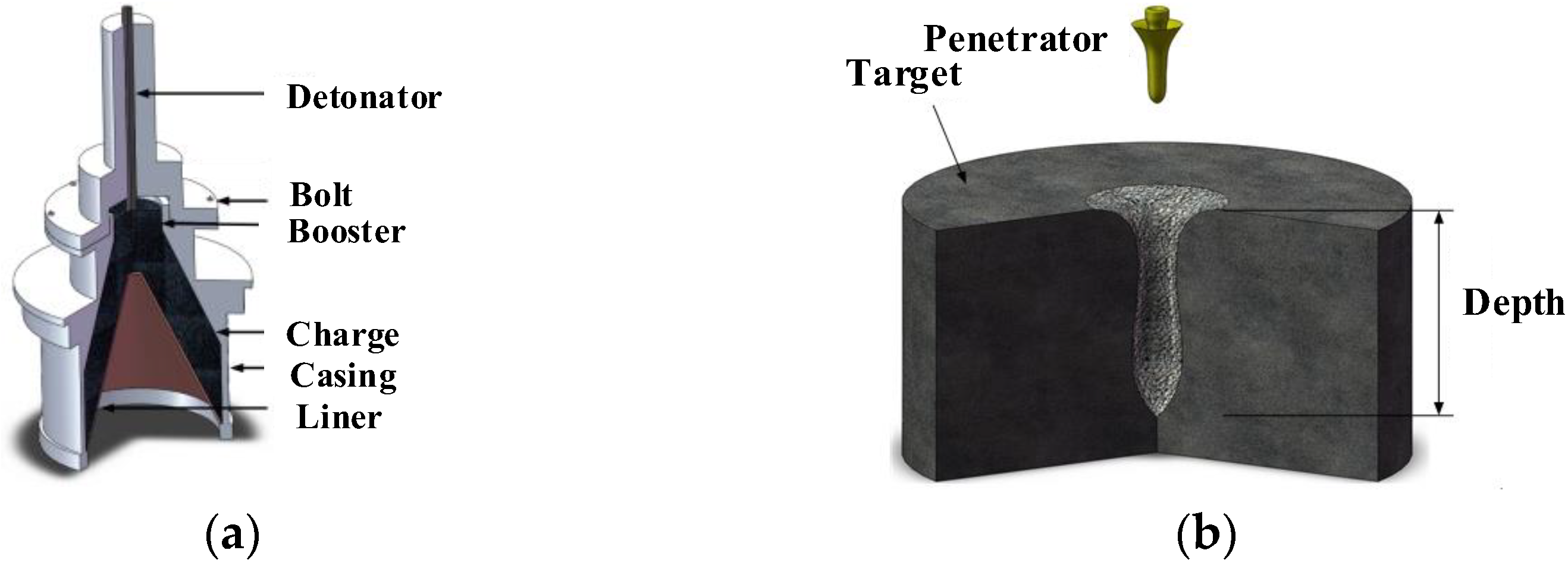
A typical shaped-charge structure [3] consists of an initiator, explosive, liner, and casing, as shown in Figure 1a. The distance from the bottom of the charge to the target is denoted as the blast height. When the initiator detonates the explosive, the liner is crushed by the huge explosive energy. The liner material moves outward along the direction which is near-vertical to the charge surface, converging in the axis direction, and forms a high-speed high-temperature metal penetration intruder. When the high-speed metal jets penetrate the target, the impact pressure acting on the target is usually extremely high (over 10 GPa), much greater than the yield strength of the target material. Therefore, the strength of the target at this stage is negligible, and the target can be treated as fluid. As the infiltration speed decreases, the target strength gradually shows its effect, causing the jet infiltration as the hole expansion capacity decreases rapidly, and it terminates the penetration when the jet energy cannot overcome the target resistance. The moment that the intruder impacts the surface of the concrete target, compression waves are generated at the contact location, and it propagates into the intruder and target, respectively. When the stress wave inside the target propagates to the surface, reflection occurs and a tensile wave is generated. Due to the low tensile strength of the concrete, the surface cratering occurs under the strong action of the tensile wave. The schematic diagram of the shaped charge penetrating the concrete target is shown in Figure 1b.
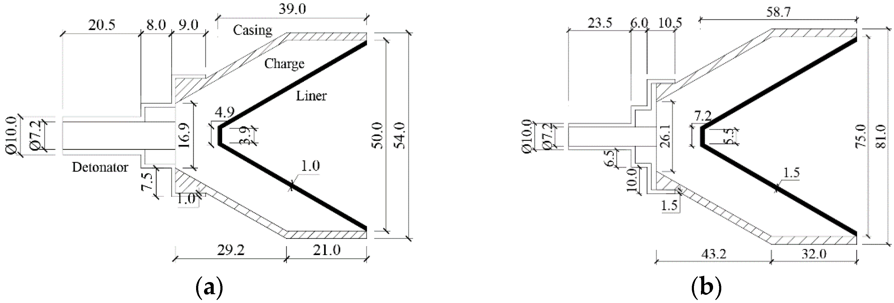
This test is designed to study whether the process of shaped charges penetrating a concrete target meets the similarity law. Thus, two types of shaped-charge structures with proportional changes in size are designed, which are denoted as small and medium shaped charges, as shown in Figure 2. With the cone angle of 60°, the charge diameters are set to 50 and 75 mm, and the thickness of the liners are 1 and 1.5 mm, respectively (the detail sizes for the two types of charges are in the ratio of 1:1.5). Figure 3a shows the photo of the structure of the shaped charge filled with B explosive (RDX:TNT = 6:4); the material of the liner is high conductivity oxygen-free copper, and the material of the casing is aviation aluminum. The concrete target is in the shape of a cylinder, and the material is C40 concrete. Two shots of test were conducted (one shot for each of the small- and medium-size shaped-charge structures), with the bomb height and target size scaled according to the proportion, and the test scenarios and the test layout are shown in Table 1 and Figure 3b, respectively. According to the similarity theory [3], the main parameters that affect the shaped-charge jet include the characteristic parameters of the shaped charge (including the explosive, casing, and liner), the target, and the relative dislocation of the bullet and target, i.e., the blast height. For the structure of the shaped charge to meet the similarity law in the process of jet formation and penetration, the jet head velocity must be equal, and the depth of penetrating the target must be proportional to the diameter of the charge. Hence, it can be concluded that the test of penetrating the concrete target with the shaped charge in this paper meets the similarity law.

3. Model Validation

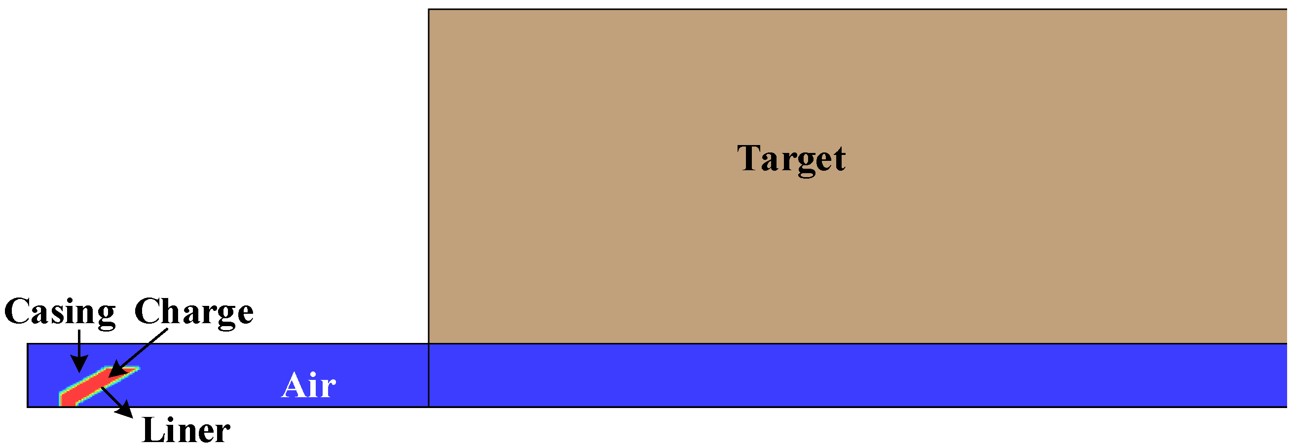
The machining of shaped charges requires high accuracy and is of great difficulty, which causes the high cost and dispersion of the experimental investigation on the shaped charge penetrating concrete. In addition, it is difficult to process shaped charges with diameters of over 100 mm. Therefore, this paper further investigates the similarity law of concrete target penetrated by shaped charge by numerical simulation. The FE software LS-DYNA is used to simulate the test of the shaped-charge jet penetrating the concrete target, and a schematic diagram of the FE model is given in Figure 4. The test setup is an axisymmetric structure, and a two-dimensional axisymmetric model is used for the FE simulation to reduce the computational time. Since no obvious visual damage occurs after the jet penetrates the concrete target, e.g., cracks on the surface and boundary, the influence of the boundary effect of the target can be ignored. Thus, it is considered feasible to simplify the model by using the two-dimensional axisymmetric method.
The ALE algorithm makes full use of the advantages of the Lagrange and Euler algorithms, with the Lagrange algorithm used for computing the material boundary calculation, which can effectively track the movement of the material boundary; and the approximate Euler algorithm is used to calculate the spatial mesh, which can effectively avoid serious distortion of the mesh by allowing the mesh to remain independent of the matter. In this paper, the ALE elements are used to simulate air, and the *INITIAL_VOLUME_FRACTION_GROMETRY keyword is used to fill the explosive and the liner at the corresponding positions in the air. The concrete target and the casing are simulated with Lagrange elements. The symmetry boundary is added on the symmetry plane of the model, and the interaction between the ALE substance and the Lagrangian concrete target is performed using the fluid–solid coupling algorithm.

3.1. Material Model and Parameterss

3.1.1. Air

Air is modeled by the Null (*MAT_NULL (009#)) material model, which allows the EOS to disregard deviatoric stress and define the viscosity. The multilinear EOS (*EOS_LINEAR_POLYNOMIAL) is shown in Equation (1) [26], where the pressure P is defined as a function of E (the energy per unit volume).
P = c 0 + c 1 μ + c 2 μ 2 + c 3 μ 3 + ( c 4 + c 5 μ + c 6 μ 2 ) E
where c0 to c6 are the EOS coefficients; μ = 1 / V 1 ; and V is the relative volume. The corresponding air parameters are listed in Table 2.

3.1.2. B Explosive

The explosive is simulated using the high explosive material model (*MAT_HIGH_EXPLOSIVE_BURN (008#)) and the JWL EOS (*EOS_JWL), in which the JWL describes the blast product pressure P as a function of volume and energy, as shown in Equation (2) [12].
P = A 1 ω R 1 V e R 1 V + B 1 ω R 2 V e R 2 V + ω E V
where A and B are constants (unit: Mbar); R1, R2, and ω are experimental fitting coefficients (unitless); e is the specific internal energy; E is the explosive detonation energy per unit volume (unit: Mbar); and V is the relative volume. The corresponding parameters are listed in Table 3.

3.1.3. Red Copper Liner and Aluminum Casing

The strength of metallic materials is related to strain, strain rate, temperature, etc., while existing experimental studies show that the material properties significantly depend on the triaxial stress state of the material. Based on the cavity growth model of Rice and Tracey, Johnson and Cook [27] proposed the Johnson–Cook (J–C) material model considering triaxial stress state, strain rate, and temperature effects. Since the J–C model describes the material comprehensively, it is widely used in FE analysis. In this paper, the J–C model (*MAT_JOHNSON_COOK (015#)) is used for all the materials, such as metal liner and casing, and can describe the strength change of metals at high temperatures and high strain rate. The yield stress σ y is expressed as Equation (3).
σ y = ( A + B ε p n ) ( 1 + c ln ε ˙ * ) ( 1 T * )
where A, B, n, c and m are material constants; T = ( T T r o o m ) / ( T m e l t T r o o m ) is the relative temperature; T, Troom, and Tmelt denote the instantaneous temperature, reference temperature (generally taken as room temperature), and material melting point temperature, respectively; ε p is the equivalent plastic strain; and ε ˙ * is the normalized equivalent plastic strain rate. The EOS of the metallic material is simulated using the Grüneisen EOS (*EOS_GRUNEISEN) [26], which is able to describe the dynamic response and behavior of the material under blast loadings, and the material pressure in the compressed state is expressed as Equation (4).
P = ρ 0 C 2 μ 1 + 1 γ 0 2 μ a 2 μ 2 1 s 1 1 μ s 2 μ 2 μ + 1 s 3 μ 3 μ + 1 2 + γ 0 + a μ E
The pressure expression of the material in the expanded state is given by Equation (5):
P = ρ 0 C 2 μ + γ 0 + a μ E
where C is the intercept of the vs-vp curve (unit: cm/μs); vs. and vp denote the burst wave velocity and mass velocity, respectively; s1, s2 and s3 are the coefficients associated with the slope of the vs-vp curve; γ0 is the Grüneisen coefficient; a is the first-order correction to γ0; μ = ρ / ρ 0 1 is the bulk strain; ρ0 and ρ denote the initial and post-deformation densities of the material, respectively; and E is the material internal energy. The corresponding parameters are listed in Table 4.

3.1.4. Concrete Target

The RHT material model [25] is suitable for describing the response of concrete under impact loading, which is used in this paper to describe the dynamic mechanical behavior of concrete. The model introduces three strength limit surfaces in the principal stress space (elastic yield surface, failure surface, and residual strength surface), which are defined using hydrostatic pressure p, effective stress σeff, and Rode angle θ, as shown in Figure 5a. The corresponding material deviatoric stress–strain relationship is divided into three phases, i.e., elastic phase (OA), strain hardening phase (AB) and softening phase (BC), as shown in Figure 5b, where σ e , σ f , and σ r are the elastic yield surface, failure surface, and residual strength surface strengths, respectively. The failure surface describes the maximum stress that the material can withstand, given in Equation (6):
σ f ( p * , θ , ε ˙ p ) = f c σ f * ( p * , F r ( ε ˙ p , p * ) ) R 3 ( θ , p * )
where fc is the uniaxial compressive strength of the cylinder; p * = P / f c is the normalized hydrostatic compressive strength; ε ˙ p is the plastic strain rate; σ f * is the normalized failure stress of compression, i.e., θ = 0; and R3 is the William–Warnke form considering the triaxiality of the stress and represents the ratio of tensile and compressive failure strengths.
σ f * p * , F r = A p * F r / 3 + ( A / F r ) 1 / n n p * F r / 3 F r f s * / Q 1 + 3 p * ( 1 f s * / Q 1 ) F r / 3 > p * 0 F r f s * / Q 1 3 p * [ 1 / Q 2 f s * / ( Q 1 f t * ) ] 0 > p * > p t * 0 p t * > p *
where p t * = F R Q 2 f s * f t * / 3 ( Q 1 f t * Q 2 f s * ) is the normalized failure cutoff pressure; and Q1 and Q2 are the shear-tension radii, respectively. F r describes the strain rate effect as Equation (8):
F r ( ε ˙ p , p * ) = F r c 3 p * F r c F r c 3 p * F r c F r c + F r t f t * F r t F r c F r c > 3 p * F r t f t * F r t F r t f t * > 3 p *
where F r c and F r t are the tensile and compressive DIFs, respectively, as Equation (9).
F r c , t ( ε ˙ p ) = ( ε ˙ p / ε ˙ 0 c , t ) β c , t ε ˙ p c , t ε ˙ p γ c , t ( ε ˙ p ) 1 / 3 ε ˙ p > ε ˙ p c , t
The elastic limit surface describes the strength of the material when it starts to enter plasticity, and the expression is given in Equation (10):
σ e ( p * , θ , ε ˙ p ) = σ f ( p * , θ , ε ˙ p ) F e ( p * ) F c ( p * )
where F e is the elasticity coefficient, and F c is the cap function.
The residual strength of the material in the residual plane is given in Equation (11).
σ r ( p * ) = f c A f ( p * ) n f   p > 0 0   p 0
The material parameters are taken as the default values of the RHT model and are listed in Table 5.

3.2. Mesh Sensitivity

A sensitivity analysis of ALE and Lagrange meshing was performed to determine the appropriate mesh size. The air was divided into 0.5, 0.75, and 1 mm ALE meshes for computation, and the velocity of the jet head was compared. It was found that the velocity of the jet head was 5360, 5150, and 4780 m/s for 0.5, 0.75, and 1 mm grids, respectively. The deviation of the jet head velocity simulated with 0.5 and 0.75 mm mesh was less than 5%, and the shapes of the jet were basically consistent, as shown in Figure 6. Therefore, the mesh size for ALE elements was chosen to be 0.75 mm. Considering the matching between ALE and Lagrange meshes and the convergence of the calculation results when the Lagrange mesh is smaller than 0.75mm, the Lagrange mesh size was also taken as 0.75 mm.

3.3. Comparisons

Figure 7 gives the process of jet forming; after the ignition of the explosive at 0 μs, the blast wave propagates circularly outward from the detonation point as the center. The liner is then crushed and accelerated, moves outward along the approximate normal direction of the explosive surface, converges and collides in the direction of the axis, and forms the elongated metal fluid with the head velocity of 5000 km/s. Because of the different acceleration processes of the liner at different positions, the velocity gradient exists in the direction of motion. Thus, the jet will be stretched in the flight process before impacting the target and divided into a higher velocity jet and a lower velocity slug.
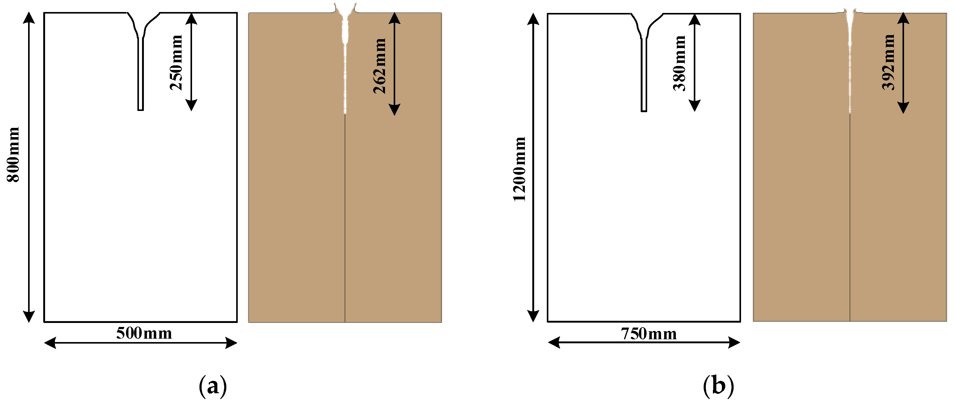
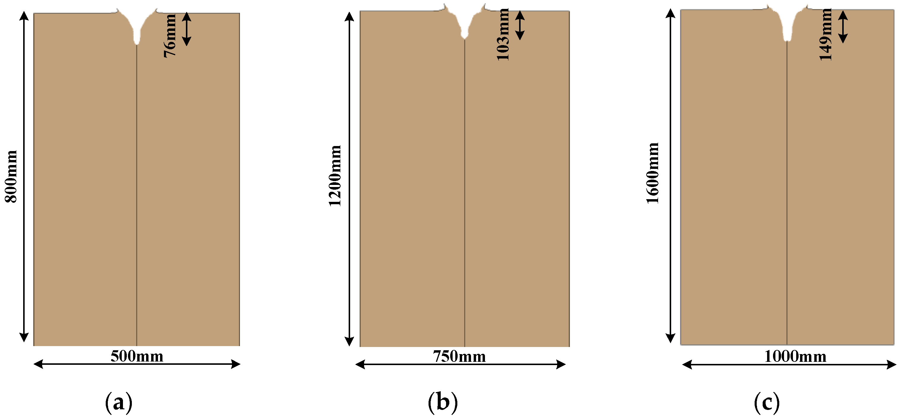
Due to the velocity gradient, the jet will stretch and fracture during the flight. After the penetration reaches a certain depth, even though there are still jet units continuing to penetrate, the depth no longer increases because the velocity of the fractured jet units that subsequently reach the bottom of the hole is lower than the critical penetration velocity, while the metal liner material accumulated at the bottom of the hole prevents the subsequent jet units from continuing to penetrate. Figure 8 shows the experimental schematic diagram and numerical simulation results of jet penetration into the concrete target, and it is found that the relative deviations of the jet penetration depth into the target under the two scenarios are both less than 5%, and the simulation results are in good agreement with the experimental data. The cratering phenomenon on the top of the concrete target in the numerical simulation is caused by the reflection of the stress wave propagating inside the target to the surface, forming the tensile wave, which indicates that the RHT material model can properly describe the tensile properties of concrete.

4. Influence of the Liner Angle

Shaped-charge jets are greatly influenced by the shaped-charge structure, which can usually be divided into three types, i.e., slender jet with a significant velocity gradient (JET), rod jet with a small velocity gradient (Jetting Projectile Charge, JPC), and explosively formed projectile with almost no velocity gradient (EFP, also known as self-forging fragment). The liner angles for these three types of shaped-charge jets are <70°, 70° to 140°, and 140° to 160°, respectively [25]. In this section, we study the similarity laws of different types of shaped-charge jets penetrating concrete targets and design two additional truncated cone-shaped liner with different angles of 90° and 150° based on the shaped-charge structure in the test. The diameters of the three shaped charges in this section are 50, 75 and 100 mm, respectively (the dimensions of the medium and large shaped-charge structures are 1.5 and 2 times those of the small one). Figure 9 gives the diagrams of small shaped charges with liner angles of 90° and 150°, and the extended scenarios are listed in Table 6.
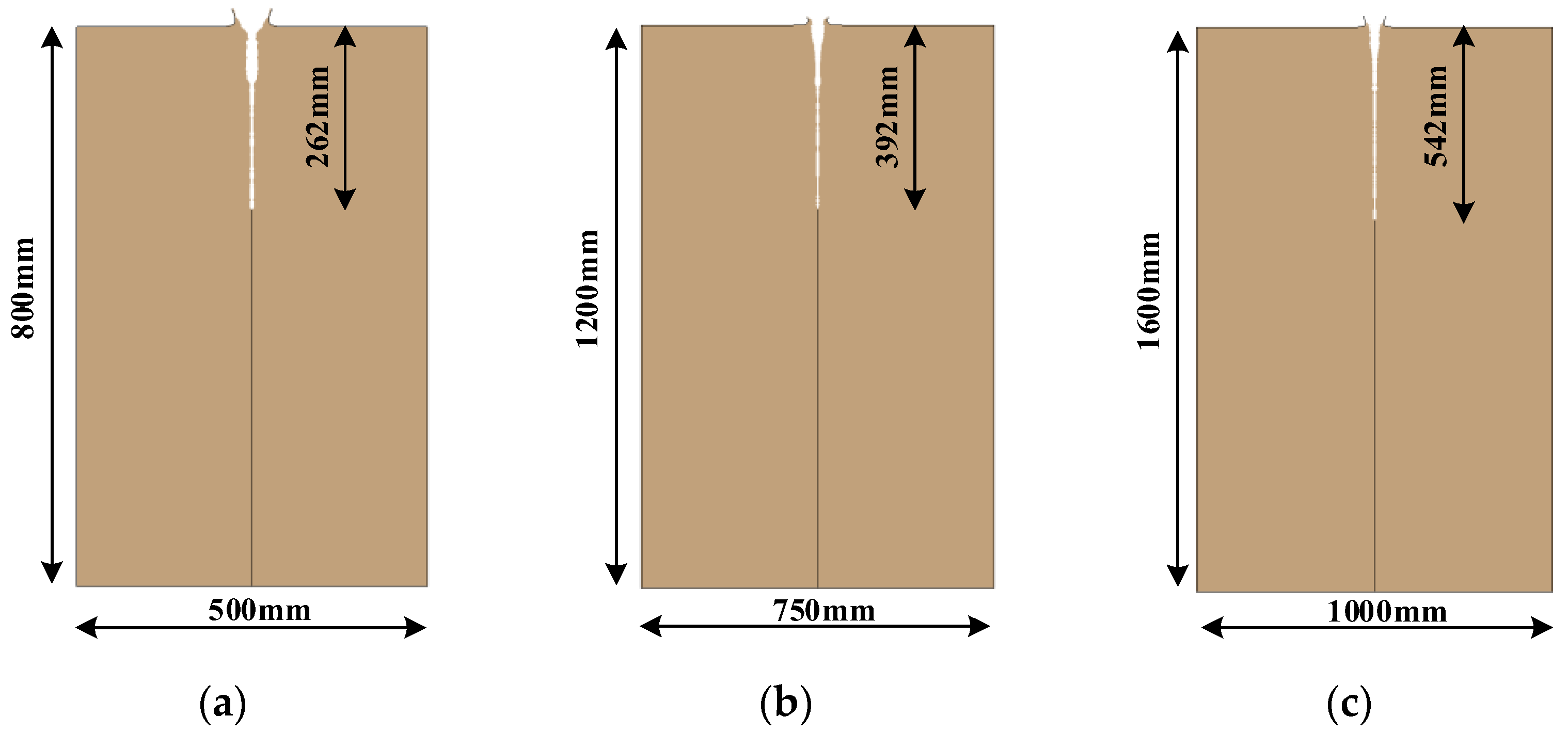
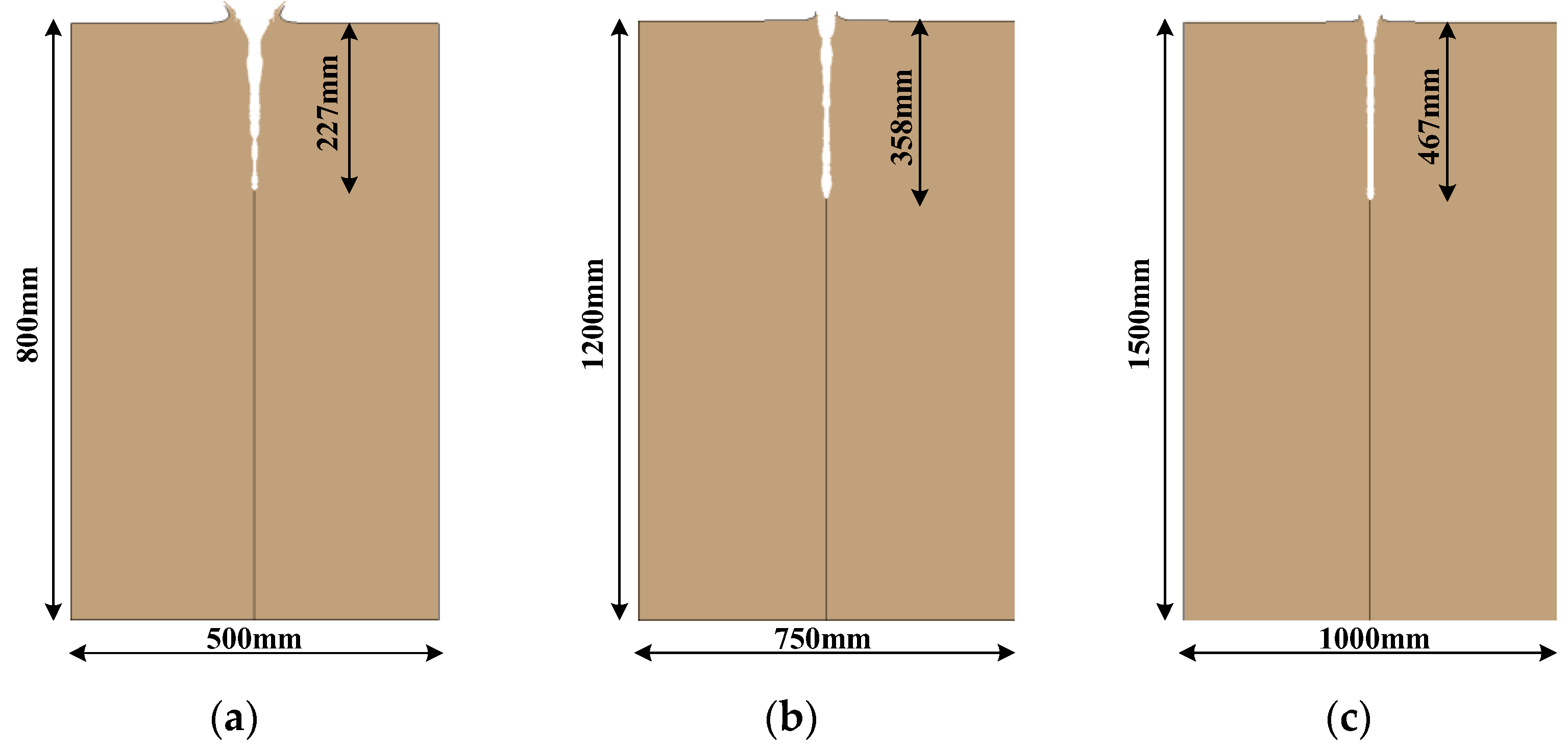
The jet formed by the shaped-charge structures with three liner angles in this paper is shown in Figure 9. JET includes slug and jet, of which the slug has large mass and low velocity (below 1 km/s) and basically no intrusion capability, while the jet part has small mass, high head velocity (about 5 km/s), and a large velocity gradient, which shows excellent intrusion performance. EFP has a shape similar to a metal disc, with a velocity of about 3 km/s and basically no velocity gradient. The jet formed by JPC has a large aspect ratio, a certain velocity gradient, and a head velocity of 4 km/s. The head velocity of JET and JPC formed by small, medium, and large shaped charges are basically the same, as well as the velocity of EFP, which indicates that the formation process of a shaped-charge jet is in accordance with the similarity law. Figure 10, Figure 11, Figure 12 and Figure 13 show the numerical simulation results of the small, medium, and large shaped-charge structures penetrating the concrete target with the liner angles of 60°, 90° and 150°, and it is found that the depth of the small, medium, and large shaped-charge structures penetrating the concrete target has a deviation of less than 12% to the similarity law, which is within the acceptable range of engineering; i.e., the process of the shaped charges penetrating the concrete target meets the similarity law. Additionally, the penetrating effect of various types of shaped-charge jets on the concrete target is different; the greater the liner angle, the higher jet velocity and the greater penetrating depth. Hence, the penetrating depth on the concrete target follows the relationship: JET > JPC > EFP. The greater the liner angle, the greater the jet diameter and the larger the crater diameter; thus, the concrete target crater area follows the relationship: EFP > JPC > JET.

5. Conclusions

In this paper, the damage effect and similarity law of a concrete target penetrated by shaped charges are studied through experiments and numerical simulation. The similarity law test for the penetration of the concrete target by the shaped-charge jets was carried out first. LS-DYNA FE software was used to reproduce the test, and the accuracy of ALE algorithm, fluid–solid coupling algorithm, material model, EOS, and corresponding material parameters was verified by comparing the penetration depths of test data and numerical simulation results. Further research on the similarity law of different types of jets (JET, JPC, and EFP) formed by shaped charges with different liner angles penetrating concrete targets was conducted. The main conclusions are:
(1) The penetration depth of the concrete target meets the similarity law under the ratio of 1:1.5 for the size of the shaped-charge structure, the target, and the burst height.
(2) The formation process of the shaped-charge jets and the depth of penetration into concrete targets meet the similarity law. It is feasible to complete the design by using a model projectile of similar conditions and then extend it to the prototype projectile.
(3) Different types of penetrators have different penetration effects on the concrete target; the larger the liner angle, the higher the jet velocity and the greater the penetrating depth of the concrete target, with the relationship of JET > JPC > EFP. The larger the liner angle, the larger the jet diameter and the larger the crater diameter, with the relationship of EFP > JPC > JET.
Author Contributions

Conceptualization, Y.Z.; investigation, W.Z.; resources, W.Z.; writing—original draft, X.Z.; writing—review and editing, F.H.; supervision, Y.Z.; funding acquisition, Y.Z. All authors have read and agreed to the published version of the manuscript.

Funding

This research was funded by National Natural Science Foundation of China, grant number 12102476.

Conflicts of Interest

The authors declare no conflict of interest.

References

  1. Zhang, M.X.; Jiao, J.J.; He, Y.; Shan, F.; Wang, H.C. Research on structure design of rear shaped charge for tandem warhead. J. Ordnance Equip. Eng. 2022. [Google Scholar]
  2. Zhao, X.; Xu, Y.J.; Dong, F.D.; Zheng, N.N.; Wang, Z.J. Simulation study on penetration of light armor by compound liner shaped charge. J. Ordnance Equip. Eng. 2022, 43, 90–95. [Google Scholar]
  3. Huang, Z.X. Theory and Practice of Shaped Charge; Beijing Institute of Technology Press: Beijing, China, 2014; pp. 19–20. [Google Scholar]
  4. Allison, F.E.; Vitali, R. A New Method of Computing Penetration Variables for Shaped-Charge Jets; Ballistic Research Laboratory Report No. 1184; Ballistic Research Laboratory: Chandigarh, India, 1963. [Google Scholar]
  5. Tate, A. A theory for the deceleration of long rods after impact. J. Mech. Phys. Solids 1967, 15, 387–399. [Google Scholar] [CrossRef]
  6. Alekseevskii, V.P. Penetration of a rod into a target at high velocity. Combust. Explos. Shock Waves 1966, 2, 63–66. [Google Scholar] [CrossRef]
  7. Tate, A. Further results in the theory of long rod penetration. J. Mech. Phys. Solids 1969, 17, 141–150. [Google Scholar] [CrossRef]
  8. Sternberg, J. Material properties determining the resistance of ceramics to high velocity penetration. J. Appl. Phys. 1989, 65, 3417–3424. [Google Scholar] [CrossRef]
  9. Forrestal, M.J.; Longcope, D.B. Target strength of ceramic materials for high-velocity penetration. J. Appl. Phys. 1990, 67, 3669–3672. [Google Scholar] [CrossRef]
  10. Satapathy, S.; Bless, S. Calculation of penetration resistance of brittle materials using spherical cavity expansion analysis. Mech. Mater. 1996, 23, 323–330. [Google Scholar] [CrossRef]
  11. Li, G.; Chen, X.W. A compressible model of radial crater growth by shaped-charge jet penetration. Explos. Shock Waves 2022, 47, 073301. [Google Scholar]
  12. Murphy, M.J. Shaped Charge Penetration in Concrete: A Unified Approach; Lawrence Livermore National Lab: Livermore, CA, USA, 1983. [Google Scholar]
  13. Murphy, M.J.; Randers-Pehrson, G.; Kuklo, R.M.; Rambur, T.A.; Switzer, L.L.; Summers, M.A. Experiments and simulations of penetration into granite by an aluminum shaped charge. In Proceedings of the 7th International Conference on Mechanical and Physical Behavior of Materials under Dynamic Loading, Porto, Portugal, 8–10 September 2003; pp. 1–6. [Google Scholar]
  14. Huerta, M.; Vigil, M.G. Design, analyses and field test of a 0.7m conical shaped charge. Int. J. Impact Eng. 2006, 32, 1201–1213. [Google Scholar] [CrossRef]
  15. Resnyansky, A.; Weckert, S. Response of an ultrahigh performance concrete to shaped charge jet. In Proceedings of the International Conference on Shock & Impact Loads on Structures, Adelaide, Australia, 2–4 December 2009; pp. 28–36. [Google Scholar]
  16. Wang, C.; Wang, W.J.; Ning, J.G. Investigation on shaped charge penetration into concrete charges. Chin. J. Theor. Appl. Mech. 2015, 47, 672–686. [Google Scholar]
  17. Elshenawy, T.; Li, Q.M. Influences of target strength and confinement on the penetration depth of an oil well perforator. Int. J. Impact Eng. 2013, 54, 130–137. [Google Scholar] [CrossRef]
  18. Ma, B.; Huang, Z.; Guan, Z.; Jia, X.; Zu, X.; Xiao, Q. Investigate the effects of magnetic fields on the penetration ability of a shaped charge jet at different standoffs. Def. Technol. 2021, 17, 1722–1730. [Google Scholar] [CrossRef]
  19. Zhang, H.; Zheng, Y.F.; Yu, Q.B.; Ge, C.; Su, C.H.; Wang, H.F. Penetration and internal blast behavior of reactive liner enhanced shaped charge against concrete space. Def. Technol. 2022, 18, 952–962. [Google Scholar] [CrossRef]
  20. Ma, T.B.; Liu, J.; Wang, Q. Influence of shaped charge structure parameters on the formation of linear explosively formed projectiles. Def. Technol. 2022, 18, 1863–1874. [Google Scholar] [CrossRef]
  21. Zhang, X.W.; Xiao, Q.Q.; Huang, Z.X.; Zu, X.D.; Jia, X.; Ma, B. Influence of Liner Material on Penetration Capability by Jet into High Strength Concrete. J. Proj. Rocket. Missiles Guid. 2020, 40, 1–4+9. [Google Scholar]
  22. Huang, Z.X.; Chen, H.W.; Guan, C. The investigation on penetration simulated rules of EFP in contact with semi-infinitude thick-sheet. J. Ballist. 2000, 12, 69–73. [Google Scholar]
  23. Tang, M.; Bo, J.S.; Li, P.; Jiang, Y.; Zhang, Z.J. Numerical Simulation Research of Explosively Formed Projectile Penetration Analogue Rule. Initiat. Pyrotech. 2006, 2, 1–4. [Google Scholar]
  24. Li, B.; Sun, J.B.; Xu, J. Numerical Simulation Research of Analogue Rule in the Process of Shaped Charge Jet Penetrate the Plate. Mechnical Manag. Dev. 2013, 2, 9–11. [Google Scholar]
  25. Hu, F. Investigations on the Destructive Effect of Two-Stage Munitions on Concrete Targets; Army Engineering University of PLA: Nanjing, China, 2015. [Google Scholar]
  26. Livermore Software Technology Corporation (LSTC). LS-DYNA Keyword User’s Manual; LSTC: Livermore, CA, USA, 2014. [Google Scholar]
  27. Johnson, G.R.; Cook, W.H. A constitutive model and data for metals subjected to large strains, high strain rates and high temperatures. In Proceedings of the 7th International Symposium on Ballistics, The Hague, The Netherlands, 19–21 April 1983; 1983; Volume 21, pp. 541–547. [Google Scholar]
  28. Chen, D.; Wu, H.; Fang, Q. Simplified separated model for brick masonry walls under out-of-plane quasi-static and blast loadings. J. Build. Eng. 2022; under review. [Google Scholar]
Figure 1. Shaped-charge structure and penetrating effect [25]: (a) Shaped charge; (b) Shaped charge penetrating concrete target.
Buildings 12 02268 g001
Figure 2. Experimental shaped-charge size (unit: mm): (a) Small; (b) Medium.
Buildings 12 02268 g002
Figure 3. Shaped charges photos and experimental layout: (a) Shaped charges photos; (b) Experimental layout.
Buildings 12 02268 g003
Figure 4. Model schematic diagram.
Buildings 12 02268 g004
Figure 5. RHT model [28]: (a) Three limit surfaces; (b) Deviatoric stress–strain relationship.
Buildings 12 02268 g005
Figure 6. Jet forms of different mesh sizes: (a) 0.5 mm; (b) 0.75 mm; (c) 1 mm.
Buildings 12 02268 g006
Figure 7. Jet formation process: (a) 0 μs; (b) 10 μs; (c) 20 μs; (d) 40 μs.
Buildings 12 02268 g007
Figure 8. Comparisons of experimental and simulated penetration depths: (a) Scenario 1; (b) Scenario 2.
Buildings 12 02268 g008
Figure 9. Sizes of shaped charges with different liner angles (unit: mm): (a) 90°; (b) 150°.
Buildings 12 02268 g009
Figure 10. Shapes of different types of penetrators: (a) JET; (b) JPC; (c) EFP.
Buildings 12 02268 g010
Figure 11. Charge diameters with liner angles of 60°: (a) 50 mm; (b) 75 mm; (c) 100 mm.
Buildings 12 02268 g011
Figure 12. Charge diameters with liner angles of 90°: (a) 50 mm; (b) 75 mm; (c) 100 mm.
Buildings 12 02268 g012
Figure 13. Charge diameters with liner angles of 150°: (a) 50 mm; (b) 75 mm; (c) 100 mm.
Buildings 12 02268 g013
Table 1. Test scenarios.
ScenarioLinerTarget Diameter (mm)Target Height (mm)Standoff Distance (mm)
1Small500800180
2Medium7501200270
Table 2. Air material model and EOS parameters [25].
ρ0 (kg/m3)c0c1c2c3c4c5c6E (J/m3)
1.29300000.40.402.5 × 105
Table 3. B explosive material model and EOS parameters [25].
ParameterValueParameterValue
ρ0 (kg/m3)1717R14.2
D (m/s)7980R21.1
PCJ (MPa)2.95 × 10⁴ω0.34
A (MPa)5.24 × 10⁵E (J/m3)8.5 × 109
B (MPa)7.68 × 10³V1
Table 4. Metal material model and parameters [25].
ParameterCopperAluminumParameterCopperAluminum
ρ0 (kg/m3)89602785C (m/s)39405328
A (MPa)90265s11.491.34
B (MPa)292426s20.60
n0.310.34s300
c0.0250.015γ01.992.0
M1.091.0a0.470
Tmelt (K)1356775E (J)00
Troom (K)293293
Table 5. RHT model parameters of concrete [26].
ParameterSymbolValueParameterSymbolValue
Relative shear strength f t * 0.18Failure surface parameterA1.6
Relative tensile strength f s * 0.1Failure surface exponentN0.61
Yield surface parameter g c * 0.53Lode angle dependence parameterQ00.6805
Yield surface parameter g t * 0.7Lode angle dependence parameterB0.0105
Residual surface parameterAf1.4Compressive strain rate exponent β c 0.036
Residual surface exponentnf0.61Tensile strain rate exponent β t 0.04
Shear reduction factor ξ 0.9Compressive reference strain rate ε ˙ 0 c 3 × 10⁻⁵ s−1
Damage parameterD10.02Tensile reference strain rate ε ˙ 0 t 3 × 10⁻⁶ s−1
Damage exponentD21Compressive break strain rate ε ˙ c 1020 s−1
Residual damaged strain ε p m 0.01Tensile break strain rate ε ˙ t 1020 s−1
Table 6. Simulation scenarios.
Liner Angle (°)Charge Diameter (mm)Standoff Distance (mm)
6050180
75270
100360
9050180
75270
100360
15050180
75270
100360
Publisher’s Note: MDPI stays neutral with regard to jurisdictional claims in published maps and institutional affiliations.