Article

Compressive Behavior of Interlocking Plastic Blocks Structural Elements Having Slenderness

Department of Civil Engineering, Capital University of Science and Technology, Islamabad 44000, Pakistan
*
Authors to whom correspondence should be addressed.
Buildings 2022, 12(12), 2257; https://doi.org/10.3390/buildings12122257
Submission received: 31 October 2022 / Revised: 7 December 2022 / Accepted: 13 December 2022 / Published: 18 December 2022
(This article belongs to the Special Issue Advances in Sustainable Building Materials)

Abstract

:
Earthquakes are among of the most harmful and potentially fatal natural disasters. Masonry structures in seismic zones of urban and rural areas around the world pose a threat to human life. Housing that is both affordable and earthquake-resistant in earthquake-prone areas is currently in demand in developing countries. For affordable earthquake-resistant structures in earthquake-prone areas, numerous researchers have studied mortar-free interlocking structures. Plastic blocks are used in order to reduce the mass of the overall structure. To start with, structures under gravity are explored first because more than 95% of its design life, any structure has to withstand gravity. Prototypes of interlocking plastic-block columns, solid walls, and walls with an opening are considered for making the mortar-free structures. In this study, the effect of slenderness on the behavior of interlocking-plastic-block structural elements is investigated under compressive loading by a servo-hydraulic testing machine in the laboratory. The effect of slenderness on the behavior of one and two-block-wide structural elements was investigated in terms of the stress–strain curve, energy absorption, and toughness index under compressive loadings. Correlations between the compressive strength of interlocking-plastic-block structural elements with varying thicknesses were found. Scaled-down prototypes of interlocking-plastic-block structural elements having two-block wide depicted more resistance to compressive loads than one block wide structural elements. The correlations among the one and two block wide interlocking-plastic-block columns, single and double-block-wide solid walls, and single and double-block-width walls with an opening found in this analysis were Pdc = 2.2 Psc, Pdsw = 2.9 Pssw, and Pdwo = 3.5 Pswo. This study can be applied in the future to better understand the detailed behavior of interlocking plastic blocks.

1. Introduction

A natural calamity that causes significant motion of the ground is an earthquake. The main effects of earthquakes include catastrophic damage, including the collapse of buildings, roads, and bridges, which may result in several fatalities. Floods and landslides can also be brought on by earthquakes. As soil with a high percentage of water acts like a fluid and loses its mechanical strength when it is severely shaken, the building can physically sink when the soil is saturated [1]. An earthquake that happens beneath the ocean floor can lead to a tsunami. Structures are often affected during intense earthquakes and can collapse. Most structures are affected during intense earthquakes and collapses. Earthquakes badly affect masonry structures due to the motion of the ground. Natural disasters such as earthquakes have seriously harmed the masonry structure system. Damage to these structures results in the loss of a lot of lives each year [2]. A Mw 6.4 earthquake hit the NW region of Albania on 26 November 2019, resulting in extensive damage to the civil structures in the broader area of Durres city and its surroundings. According to the official statistics, it caused 51 deaths and 1.2 billion US dollars in economic losses [3]. The seismic events that hit Central Italy in August–October 2016 affected a rather large area, spread over four Italian regions and including 140 municipalities and 2100 urban sites [4]. Recent earthquakes that have happened across the globe have demonstrated that unreinforced masonry (URM) buildings built according to outdated codes may be a significant source of risk. It is well recognized that the volumetric relationship between the wall texture and the components, and the compressive and shear strengths of the bricks, all affect how mechanically responsive masonry constructions are [5].
Therefore, in order to evaluate the risk brought on by induced seismicity, the seismic susceptibility of various types of red clay brick and calcium silicate brick masonry structures must be determined. Since a minor earthquake struck the area lately (26 November, Durres), the usual construction methods revealed a lack of earthquake-proof details [6]. The majority of the Lower Town’s structures, including brick masonry buildings, colleges, schools, kindergartens, hospitals, and public buildings, were devastated by the main earthquake. The vast majority of structures constructed in the former Yugoslavia after the country’s first earthquake laws went into effect (1964) were either unharmed or only moderately damaged [7]. On 28 April 2021, a moderate earthquake with a local magnitude of 6.4 struck Sonitpur, Assam, India. Despite the fact that the earthquake happened in India, Bhutan had significant structural and infrastructure damage, particularly in the eastern provinces. It may be noted that during a seismic event, each structure has to withstand the combination of seismic and gravitational forces. Other than the seismic event, the structure will only have to primarily withstand gravity loads. However, seismic events cannot be ignored. To start with, structures under gravity should be explored.
Various brick masonry failures—corner overturning, horizontal bending provoking out-of-plane leaves separation, masonry crumbling and pounding, out-of-plan failure of unreinforced masonry walls, and building collapse—have been reported [8]. In the seismically active regions, economical earthquake-resistant housing is desirable, especially in rural areas of developing counties. During strong ground motion, these regions often suffer a significant loss of life because of the lack of seismic resistance of their houses. Research indicates that several earthquake-resistant development strategies and approaches have been used for the stated goal. For instance, in masonry constructions, there are provision of plinth beams, lintel band beams, and vertical stiffeners. Stiffeners were introduced by French structural engineer and builder Paul Cottancin to strengthen masonry structures [9]. Many scholars have already investigated the seismic behavior of masonry structures in laboratories. Under time-scaled Nahnni earthquake conditions, the extremely non-linear behavior of unreinforced masonry was seen in laboratory tests.
For reinforced brick masonry, concrete stiffeners improved the strength and rigidity of the masonry structures. This phenomenon has been verified by laboratory testing and actual earthquake loading. During the laboratory testing, the failure modes transitioned from shear slip or diagonal tension to diagonal tension and toe-crushing. Reinforcing materials have been incorporated into mortar joints to protect structures from cracking [10,11,12]. For residents in such locations, it is necessary to build affordable but safe homes. One of the conceivable possibilities is an interconnecting framework. Ali [13] developed a mortar-free structure (a new construction technique) for earthquake-resistant housing. In recent decades, many researchers have investigated the quality of mortarless masonry subject to compressive loading [14,15,16,17]. Ahmad et al. [18] measured the compressive strength of a mortar-free, interlocking concrete-brick masonry wall. According to researchers, the inherent strain of a mortar-free wall permits it to be employed in residential constructions. Furthermore, the lack of mortar between bricks allows for friction on the surfaces of the bricks, which may boost a structure’s energy dissipation capability during seismic actions [13].
A mortar-free interlocking plastic-block structure has the ability to dissipate the energy of an earthquake. A mortar-free interlocking-block structure can the dissipate energy of an earthquake. Due to the slanted key between the blocks, interlocking blocks can return to their former locations after a ground motion. Xie et al. [19] observed the apparent inter-brick oscillation in the interlocking brick walls, leading to a substantial amount of energy dissipation through friction, which greatly outweighs the energy dissipated by brick damage. During applied earthquake loadings, the vertical relative movement had been seen at the interface of interlocking blocks in the mortar-free column [20,21,22].
The rubberized interlocking blocks were used by Fakih et al. [23]. They showed favorable results, and it was proven that these blocks can be used for real construction in load-bearing brick masonry, as their strength is 18.4 MPa, which is greater than the required strength (13.7 MPa). The coconut-fiber-reinforced interlocking concrete blocks invented by Ali et al. [24] also gave outstanding results. The compressive strength of these blocks was 20 MPa, which is sufficient for a single-story earthquake-resistant house.
Due to its advantages—enhancing field productivity and building efficiency with potentially less skilled labor and hence lower costs—the interlocking masonry system has recently become well known in the construction industry for load and non-load-bearing applications [25]. Currently, mortar-free masonry buildings made of interlocking bricks have generated a lot of interest in the construction industry [26,27]. The authors of [28] conducted a review on masonry structures built with interlocking bricks, and the results showed that adopting interlocking bricks may greatly increase construction efficiency when compared to using ordinary bricks. Furthermore, the interlocking mechanism of bricks can assist assure alignment, robustness, and strength needs, which can improve the construction quality of masonry structures and significantly lower the need for labor skills. Interlocking bricks are joined by interlocking tenons and mortises rather than the comparatively weak mortar for typical bricks, the shear strength of which can be equated to the bond strength between mortar and masonry units in normal mortared masonry [29].
Figure 1a shows a newly constructed residential building which has been constructed with interlocking compressed earth bricks [30]. Gul et al. also constructed a full-scale house with unconfined dry-stacked blocks, as shown in Figure 1b [31]. Figure 1c shows the full-scale-dry stacked masonry structure by Elvin et al. [32]. The corresponding blocks used for specific study are also shown with the masonry structure. One of the crucial factors to understand when designing masonry walls for different loading effects, such as compression, in-plane shear, and out-of-plane flexure, is the compressive strength of the material. In numerous clay brick masonry buildings all around the world, the bonded brickwork walls are another typical component. These structures are frequently regarded as significant components of heritage, so figuring out how they actually support loads is crucial to preserving them. Therefore, it is crucial to accurately anticipate the compressive strength of masonry in order to properly design new components and assess the strength of existing masonry buildings. In order to determine the compressive strength required by masonry codes, specifications, and standards, two approaches have been developed, one of which is the unit prism strength method. However, the geometry and their interfaces determine the cracking pattern and the ultimate load-bearing capacity of the masonry wall panel Sarhosis et al. [33].
Ahmad et al. [18] evaluated the masonry wall’s compressive strength that used interlocking concrete bricks constructed without mortar. According to studies, a mortar-free wall’s inherent tension makes it suitable for usage in residential structures. The failure mechanism and cracking behavior of rubberized interlocking concrete hollow and grouted prisms have been investigated by Fakih et al. [23]. The sides of the bricks had severe fractures, which were detected. For both hollow and grouted prisms, the failure mode was characterized by face spalling and web splitting at the center along the longitudinal direction. The interlocking mechanism caused the web to fracture, putting it under a lot of strain. Ali [34] tested the compressive strength of CFRC interlocking blocks using a compressive testing machine in the laboratory. With increasing slenderness, the impact of brickwork compressive strength decreases. Only the overall stiffness, which is defined by the elastic moduli of the expanded units in the wall, is crucial in the scenario of high slenderness; the majority of the walls show stability failure [35].
Inherently, the slenderness ratio plays a large part in unplanned behavior due to compressive arching action phenomena; nevertheless, the slenderness ratio may reduce or eliminate the arching action [36]. The ultimate displacement capacity, ductility, and energy dissipation ability of the wall were all lowered by 25% when the wall thickness was reduced by 25% [37]. Apart from the preceding investigations on the performance levels of specific designs by various experts, thorough studies on the mechanical properties of interlocking bricks are still needed. Zahra et al. [38] discovered that think bonded brickwork walls constructed with prisms of double and triple bricks are common in load-bearing historical brick-masonry buildings in various countries, necessitating interventions and compression capacity testing. The bonded brickwork’s slenderness ratios ranged from 1.4 to 10.9. The strength under compression of bonded brickwork decreases as the slenderness ratio increases for all bonded thicknesses, according to the findings. In the last few decades, many studies have looked into the quality of mortarless brickwork that has been subjected to compressive loading. The compressive strength of a masonry wall composed of mortar-free interlocking concrete bricks was evaluated by a number of researchers [39].
These arguments conclude that the behavior of interlocking plastic blocks-based structural elements under axial compression is different to that of two-block-wide structural elements; and previous research studies on the compression responses of interlocking plastic blocks-based structural elements were mostly centered on the one-block-wide structural elements. The specific aim of this research work was to investigate the effect of slenderness on the compressive behavior of scaled-down prototypes of interlocking-plastic-block structural elements, i.e., columns, solid walls, and walls with door openings, using the servo-hydraulic (compressive) testing machine in the laboratory. Load–deformation curves were recorded during experiments of servo-hydraulic testing, which were then transformed into average stress–strain curves to compare the properties of interlocking plastic blocks-based structural elements with different thicknesses. Energy absorption before and after cracking were than calculated using area under curve by Simpson’s rule. The toughness index for each interlocking plastic blocks-based structural element was then determined. The relationship between the stress values was developed.

2. Experimental Work

Ground acceleration is transferred from the ground to the foundation of the structure, which causes inertia to damage the masonry walls. The literature indicates that various building techniques have been adopted in the form of structural components to build earthquake-resistant masonry buildings. One new earthquake-resistant technique is the construction with interlocking blocks. However, the bigger inertial forces due to the greater masses of these conventional building blocks are a problem. This chapter includes many topics, such as the proposed scaled-down structural elements, compression testing of the interlocking-plastic-block structural elements, test setup, compressive loading, analyzed parameters, stress–strain curves of the interlocking plastic blocks-based structural elements, and development of correlations.
A lot of techniques are being studied to reduce the effects of earthquakes on structures. The compressive behavior of interlocking plastic block units and its structural elements was evaluated by Aslam S. [40]. It was observed that the compressive capacity of a prism with two blocks was greater than that of a prism with three blocks due to the slenderness effect. Prototype testing [35,38] serves to provide specifications for a real or proposed working system rather than a theoretical one. The prototype wall-scaling and construction technique adopted in this research work is purely based on the research practices mentioned in the literature by Keivan et al. [41]. The outcomes of such studies help to explain the behavior of full-scale structures.
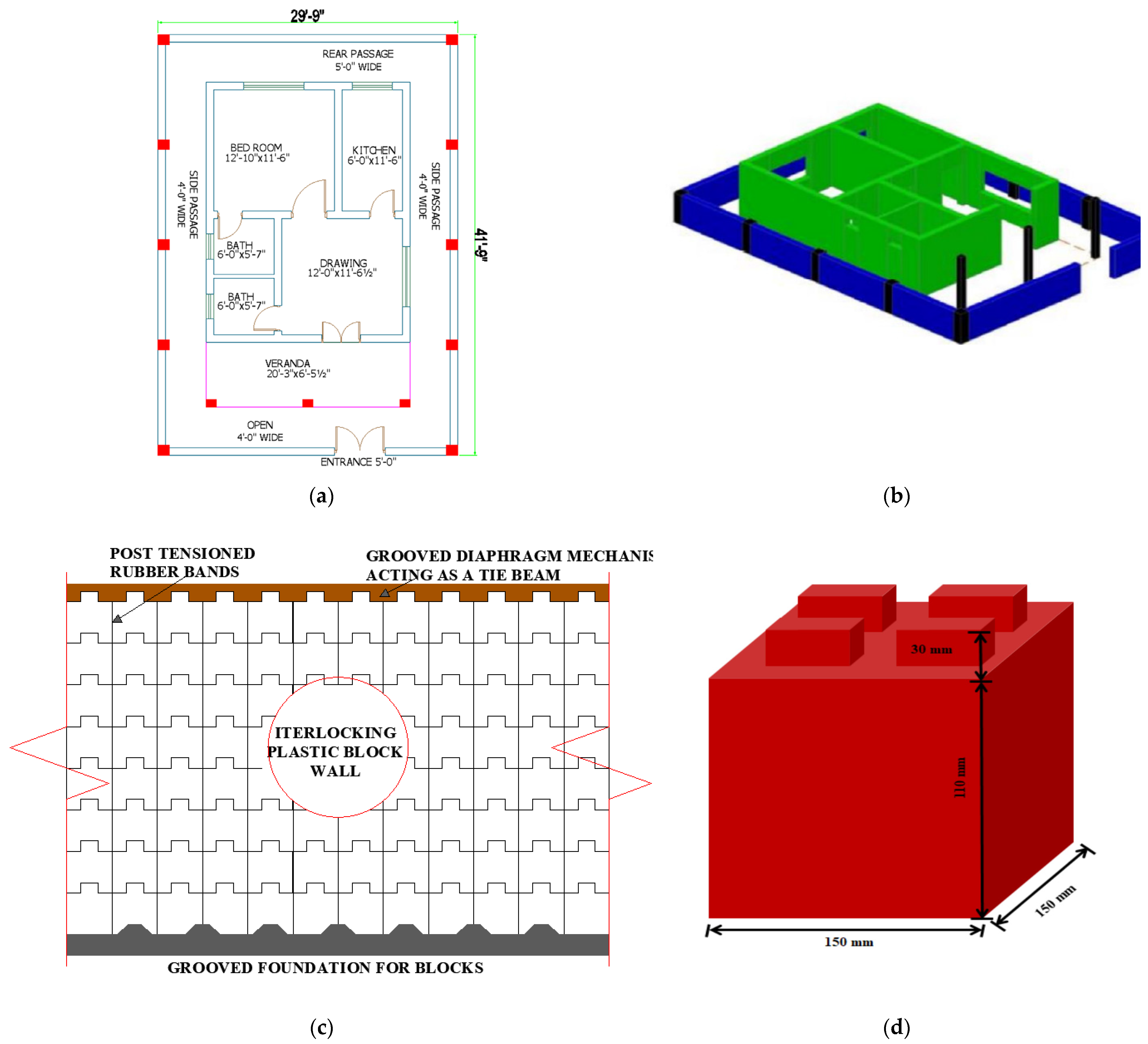
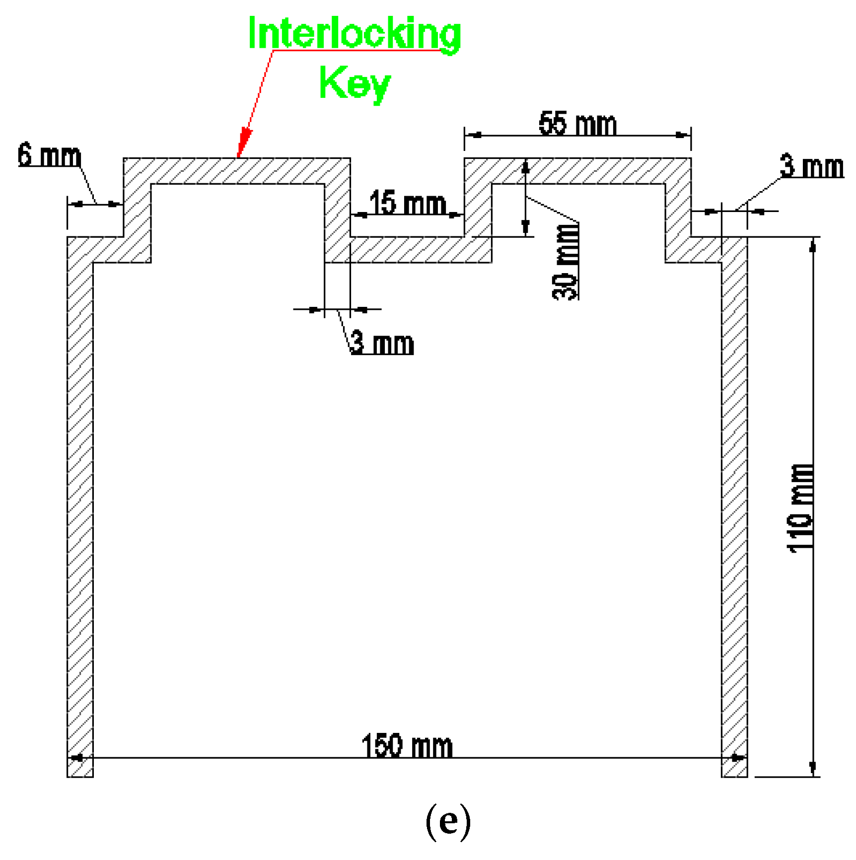
Different methods had been used all around the world for this specific assessment. The methods of assembling the interlocking-plastic-block columns, solid walls, and walls with door openings; test setup and instrumentation; analyzed parameters; and correlations between the effects of slenderness on the behavior of the interlocking structural elements of the plastic blocks, i.e., columns, solid walls, and walls with door openings, under compression, are all defined in this study. The interlocking plastic block for an earthquake-resistant house was proposed by Khan [42]. A typical 5 marlas (approximately) house plan and 3D view of proposed house is shown in Figure 2a,b. A wall assembly with the provision of foundations and a grooved diaphragm mechanism acting as a tie beam is shown in Figure 2c. A cross-section of an interlocking block is shown in Figure 2d. As far as horizontal connections are concerned, a tie beam will be provided at the level of the roof.

2.1. Construction of Scaled-Down Prototypes of Structural Elements

Prototypes were an interlocking plastic block column (one-block-wide) having thirteen interlocking plastic blocks, making a total height of 762 mm; another column of two-block width having fifty two interlocking blocks making a total height of 762 mm; a solid wall with a height of 762 mm consisting of one hundred and fifty six interlocking blocks; a similar solid wall with two-block wide consisting of three hundred and twelve interlocking plastic blocks; a one-block-wide wall with a door opening having one hundred and twenty interlocking plastic block units; and a two-block-wide wall with a door opening having two hundred and forty interlocking plastic blocks.
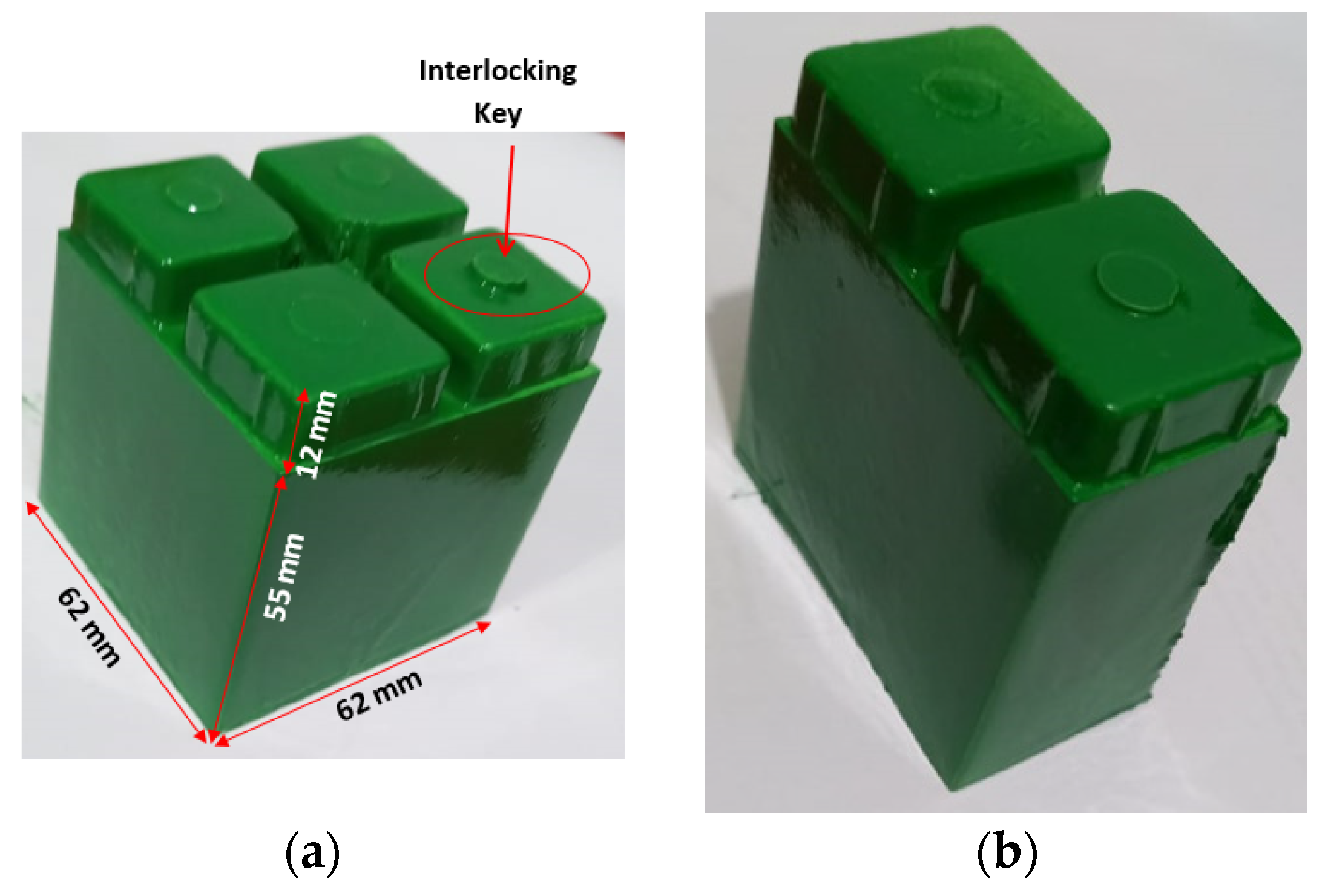
The walls with an opening had openings in the form of a door in the middle. The dimensions of such openings were 248 × 495 mm. Wooden lintel was provided above the opening for a support mechanism. Figure 3 illustrates the interlocking plastic blocks, i.e., the stretcher and half block used in this study. In addition, rubber bands were used from bottom to top through middle of blocks to provide vertical stiffness to interlocking plastic blocks-based structural elements. A rubber band provided integrity to the prototypes of interlocking plastic blocks-based structural elements, and it also prevented sudden failure of structural elements in terms of buckling. A rubber band’s plastic deformation will be high, which ultimately results in greater post-crack energy dissipation and a higher toughness index. The schematic diagrams of all structural elements are shown in Figure 4. A post tension rubber band has also been used in lieu of vertical reinforcement. Only the elevation measurements were scaled down by 10/4 due to (i) time period dependency as per method A of UBC 97, which depends upon height of the structure, and (ii) the limitation of the servo-hydraulic testing machine.

2.2. Test Setups

Uniaxial compression tests were performed on an interlocking plastic block one-block-wide column, two-block-wide column, a one-block-wide solid wall, a solid wall with two-block-wide, a wall with a door opening having one-block wide, and a wall with a door opening with two-block width, all made of interlocking plastic block units. The height of all these structural elements was same, i.e., 762 mm. All the interlocking-plastic-block structural elements were tested in a servo-hydraulic testing machine to determine the average compressive capacity (σ), corresponding global strain (ε), modulus of elasticity (E), and total compressive toughness (Tc). To prevent any local failure of interlocking plastic blocks and to distribute the applied load uniformly, samples were centrally mounted in the servo-hydraulic testing machine and capped at the top and bottom of the face shells by wooden planks. For the wall samples, wooden planks were placed on the top and bottom to ensure the uniformity of the load.
The compressive capacity of each of the interlocking-plastic-block structural elements was obtained by using the servo-hydraulic testing machine, and the test was performed in compliance with the requirements of ASTM D695-02a. The speed of the servo-hydraulic testing machine compressing the samples was 0.02 kN/sec until failure. Figure 5 shows the instrumentation of the compression test for the one-block-wide column, column having two-block wide, one-block-wide solid wall, solid wall with two-block wide, wall with a door opening having one-block wide, and wall with a door opening with two-block width, all made of interlocking plastic block units. The column of interlocking plastic blocks was made and tested under compressive loads as per the method prescribed in ASTM D695-02a, using the servo-hydraulic testing machine.
The height of both columns, i.e., the one-block-wide column and two-block-wide column, was 762 mm. The thickness of the one-block-wide column was 62 mm, whereas for two-block-wide column, the thickness was 124 mm. The interlocking-plastic-block columns were put centrally in the servo-hydraulic testing machine to ensure uniform distribution of applied loads and to prevent any local block failure. Both solid walls i.e., one and two-block-wide ones, and both with door openings (one with one-block width and other with two-block width) had dimensions of 762 mm length, 762 mm height. The thickness of the one-block-wide column, solid wall, and wall with a door opening was 62 mm; on the other hand, the thickness was double for the two-block-wide column, solid wall, and wall with a door opening: 124 mm. Test setups and instrumentation of all the selected interlocking-plastic-block structural elements is shown in Figure 5. The one-block-wide solid wall was made of 13 courses. The first course at the bottom contained thirteen stretcher-type interlocking plastic blocks (SB), the second course contained twelve stretcher-type interlocking plastic blocks (SB) and two half interlocking plastic blocks (HB). On a wooden plank, the first course of the interlocking blocks was laid out tightly in a straight line. The four interlocking keys on the top shell-face surface were positioned closely to the cavity part on the bottom shell-face surface of the block.
The solid walls and walls with an opening in the form of a door were made using interlocking plastic blocks with stretcher bonds. The stretcher block was the main unit of the wall panel, and the half interlocking plastic block was used to construct the wall course. These interlocking keys and cavities allow the blocks to interlock with other blocks placed above and below. By adopting the same procedure, the whole wall was constructed. For the two-block-wide solid wall, two rows of interlocking plastic blocks were staggered on interlocking plastic blocks on both edges along the length of the wall. On both edges along the width of the two-block-wide solid wall, the series of half interlocking plastic blocks and the wooden plank were parallel to each other horizontally. In the second course, twelve interlocking plastic blocks were used to seal the joint between the first rows; half were staggered in the second row. This staggering technique was repeated for thirteen rows vertically. Wooden lintel was provided above the opening in the wall as a support mechanism. Solid walls and walls with door openings were capped with wooden planks on the bottom and top to ensure uniform vertical load distribution. Interlocking-plastic-block structural elements’ labels are shown in Table 1.

2.3. Evaluated Parameters

All the interlocking-plastic-block structural elements were tested in a servo-hydraulic testing machine to determine the average compressive capacity (σ), corresponding global strain (ε), modulus of elasticity (E), and total compressive toughness Tc. To prevent any local failure of interlocking plastic blocks and to distribute the applied load uniformly, samples were centrally mounted in the servo-hydraulic testing machine and capped at the top and bottom of the face shells by wooden planks. For the wall samples, wooden planks were placed at the top and bottom to ensure the uniformity of the applied load. During testing load–deformation curves were recorded, which were then transformed into average stress–strain curves for examining the properties of interlocking-plastic-block structural elements with different thicknesses. Correlations between the compressive capacities of interlocking-plastic-block structural elements were developed in this work. The output of the interlocking mechanism was also analyzed, and the failure mode was tested.

3. Results

This chapter includes many topics, such as observed compressive behavior of one and two block wide interlocking plastic blocks structural elements, load-deformation and stress-strain curves of tested prototypes and development of correlation among one and two block wide structural elements, and also the correlation between solid walls and walls with opening.

3.1. Compressive Behavior

It was observed that the one-block-wide column buckled from the middle with a sudden impact, and cracks were observed at the bottom corners of the middle block. Additionally, the blocks in the lowest part of the above-mentioned specimen intruded into each other, and one of their corners was also broken. Due to the presence of the rubber band, the one-block-wide column was not split into individual blocks; however, it did collapse. Unplanned behavior was observed in the case of the two-block-wide column. Initially, at the bottom, some of the half blocks showed slippage, which means a more stable foundation is required, and then buckling started at the middle of the column. Some cracks also developed at the uppermost blocks. The two-block-wide column gave some warning before buckling failure, unlike the case of the one-block-wide column—i.e., its sudden failure, as shown in Figure 6. Maximum deviation from the centerline was observed in the middle height-wise. In the case of the one-block-wide solid wall, bucking was detected, though minor, but when the load increased, its physical behavior changed, though it stayed erect. The reason was the interlocking forces applied by some internal flexible rubber: it held the bricks together, and the whole block wall has some brittle behavior as a consequence. At maximum load, the uppermost layer of blocks started cracking, and the one-block-wide solid wall then collapsed. The two-block-wide solid wall handled the highest load of all structural elements. The internal stress absorbed the load and gave warning signs before collapse began. The load was handled uniformly; therefore, it took the maximum load and took the maximum time to fully collapse. In addition, the blocks in the upper portion took the load but did not collapse.
In the case of the one-block-wide wall with a door opening, the cracks were observed in one of the corner blocks around the top of door opening and also in the blocks on which the lintel was resting, as shown in Figure 6. This indicates that the load was transferred to the wooden support which acted as the beam. One of the sides of the opening was showing failure in the shells of blocks on which the lintel was resting. Diagonal cracks were observed on one of the sides around the opening. The behavior and failure mechanisms of all tested interlocking-plastic-block structural elements are shown in Figure 6. In the case of two-block-wide wall with a door opening, the cracks were observed in one of the corner blocks around the top of the door opening and also in the blocks on which the lintel was resting. This indicates that the load was transferred to the wooden support which acted as a beam. One of the sides of opening was showing failure of shells of blocks on which the lintel was resting. Diagonal cracks were observed on one of the sides around the opening.

3.2. Stress–Strain Curves

The load–deformation values were recorded during experiments and converted into load-deformation curves are shown in Figure 7a. The peak load carrying capacity of the two-block- wide column is higher than that of the one-block-wide column due to the high slenderness ratio of the one-block-wide column. Similarly, for the solid walls and walls with an opening, the same trend was observed. The load–deformation curves were than transformed into average stress–strain curves to compare the properties of interlocking plastic blocks-based structural elements with different thicknesses. For a one-block-wide interlocking-plastic-block column, the maximum load was 1.3 kN, and the corresponding deformation was 1.068 mm. For a two-block-wide interlocking-plastic-block column, the peak load was 2.8 kN, and 4.718 mm was the corresponding deformation. The peak load for the two-block-wide column was higher than that of the one-block-wide column. This was due to high slenderness ratio in the one-block-wide column. For the one and two-block-wide interlocking plastic block solid walls, the peak loads were 4.1 and 11.7 kN, respectively; and the corresponding deformations were 6.42 and 26.95 mm respectively. For the one and two-block-wide interlocking-plastic-block walls with a door opening, the maximum load values were 1.1 and 3.7 kN, respectively, and the corresponding deformation values were 3.11 and 10.72 mm, respectively.
The average stress of the one-block-wide column was obtained by dividing the peak load by its cross-sectional area (load-bearing area, i.e., top and bottom), and its global corresponding strain was obtained by dividing deformation by its original length. By adopting the same procedure, stress–strain values for other structural elements were also obtained. For one and two-block-wide columns the average stress values were 3.85 and 2.28 MPa, respectively; and their corresponding global strain values were 0.0017 and 0.0321, respectively. The average stress of the two-block-wide column was less than that of the one-block-wide column because of fact that the two-block-wide column having almost four times the cross-sectional area as the one-block-wide column. For one and two-block-wide solid walls the average stresses were 0.94 and 1.36 MPa, respectively; and their corresponding global strain levels were 0.057 and 0.068, respectively. For one and two-block-wide walls with a door opening, the average stresses were 0.39 and 0.68 MPa, respectively; and their corresponding global strains were 0.0201 and 0.0724, respectively. From the above values, it is clear that (in case of walls) as the slenderness ratio increases, stress decreases. In current study, as the height was constant, by increasing thickness, stress values are also increased. However, in the case of columns, this assumption was not fulfilled. Stress–strain curves of all tested interlocking-plastic-block structural elements are shown in Figure 7b.

3.3. Energy Absorption and Toughness Index

The amount of energy absorbed per unit area during a specific deformation is referred to as the capacity of energy absorption. The ratio of the total area to the area before the cracks under the stress–strain curve is known as the toughness index. The peak load and global strain for the one-block-wide column were 1.3 kN and 1.7 × 10⁻³, respectively. The compressive capacity of the one-block-wide interlocking-plastic-block column was 3.85 MPa. At peak load, cracking initiates, and the area under the stress–strain curve to this point is known as the energy absorption up to peak load. Similarly, the area under the curve after peak load is known as the energy absorption after peak load. Its energy absorption and compressive toughness were 5.06 × 10⁻³ Nm and 1.05, respectively. The peak load for the two-block-wide column was 2.8 kN. The peak load for the one-block-wide column was less than the peak load for the two-block-wide column due to the former’s higher slenderness ratio. The compressive capacity of the two-block-wide column was 2.28 MPa. The energy absorption and compressive toughness for the above-mentioned specimen were 56.06 × 10⁻³ Nm and 4.09, respectively.
The average stress of the one-block-wide solid wall was 0.94 MPa. The energy absorption and compressive toughness for the one-block-wide solid wall were 29.61 × 10⁻³ Nm and 4.79, respectively. The compressive strength (compressive capacity) of the interlocking two-block-wide solid wall was 1.36 MPa. Its energy absorption and compressive toughness were 45.55 × 10⁻³ Nm and 1.73, respectively. The energy absorption of the two-block-wide solid wall was greater than the energy absorbed by the one-block-wide solid wall because of the larger deformation in the two-block-wide solid wall. The compressive capacities of one and two-block-wide walls with a door opening were 0.39 and 0.68 MPa, respectively. The energy absorption and compressive toughness for the two-block-wide wall with a door opening were 31.61 × 10⁻³ Nm and 4.2, respectively. The energy absorption and compressive toughness for the one-block-wide wall with a door opening were 5.11 × 10⁻³ Nm and 4.02, respectively. A material is said to be ductile if it can resist plastic deformation without rupturing. Therefore, materials with high ductility will have a high toughness index. According to the findings, interlocking-plastic-block samples had a small area under the curve after cracking, which is a sign of their brittle behavior. Experimental energy absorption and toughness index values of all tested interlocking-plastic-block structural elements are shown in Table 2.

4. Correlations for Comparison

The compressive strengths of one-block-wide and two-block-wide interlocking plastic block structural elements are correlated. It is concluded that the peak load for the two-block-wide column was greater than that for the one-block-wide column, the peak load for the two-block-wide solid wall was more than that of the one-block-wide solid wall, and the peak load for the two-block-wide wall with a door opening was greater than the peak load of the one-block-wide wall with a door opening. The compressive strengths of solid walls and walls with opening are also correlated.

4.1. Correlation between Load Carrying Capacities of One and Two-Block-Wide Structural Elements

As observed during experimentation, the peak load carrying capacity for the one-block-wide column was 1.3 kN, which was less than peak load of the two-block-wide column, i.e., 2.8 kN. This was due to the one-block-wide column having a higher slenderness ratio than the two-block-wide column. However, due to its higher cross-sectional area, the stress level of the two-block-wide column was higher than that of the one-block-wide column. The peak load of the one-block-wide solid wall was 4.1, kN which is less than the peak load of two-block-wide solid wall—i.e., 11.7 kN. This was also due to slenderness ratio and due to more bearing area in the case of a two-block-wide wall. As far as the stress is concerned, the behavior is same as that for a bonded-brick-work case. By increasing the slenderness ratio, the load carrying capacity decreases [43]. The stress of the two-block-wide solid wall (slenderness ratio is less) was higher than the stress of the one-block-wide solid wall (slenderness ratio is high).
For the walls with door openings, one and two-block-wide, the peak load carrying capacities were 1.1 and 3.7 kN, respectively. The peak load carrying capacity for the two-block-wide wall with a door opening was greater than that of the one-block-wide wall with an opening. Again, the slenderness ratio was grater in the case of the one-block-wide wall with an opening. The peak load for the two-block-wide column was equal to 2.2 times the peak load for the one-block-wide column. The peak load for the two-block-wide solid wall was equal to 2.9 times the peak load of the one-block-wide solid wall. The peak load for the two-block-wide wall with a door opening was equal to 3.5 times the peak load of the one-block-wide wall with a door opening. Similar results were also observed by Jaafar et al. [15] in their interlocking hollow concrete blocks: the compressive strength of a wall panel was higher than the compressive strength of a prism with three blocks and a unit block.
To sum up the similarities elements, we present Table 3, where Psc is the peak load for the one-block-wide column, Pdc is the peak load for the two-block-wide column, Pssw is the peak load for the one-block-wide solid wall, Pdsw is the peak load for the two-block-wide solid wall, Pswo is the peak load for the one-block-wide wall with a door opening, and Pdwo is the peak load for the two-block-wide door wall with an opening.

4.2. Correlation between the Load Carrying Capacities of Solid Walls and Walls with Openings

The peak load carrying capacity of the one-block-wide solid wall was 4.1 kN which is more than peak load carrying capacity of the one-block-wide wall with a door opening, i.e., 1.1 kN. Similarly, the peak load carrying capacity of the two-block-wide solid wall was 11.7 kN, which is greater than peak load carrying capacity of the two-block-wide wall with a door opening, i.e., 3.7 kN. Similar results were also observed by Aslam. S. [40] for his interlocking plastic blocks, in that the maximum load carrying capacities of the solid walls were higher than the peak load carrying capacities of the walls with an opening. A door opening in the wall causes more plastic deformation compared to a solid wall. It was observed that the solid wall specimens continued to gain strength with reduced stiffness until the final strength was reached.
Unlike solid walls, sudden failure was observed in the walls with door openings. The total area of the opening was 24%, and the decreases in peak load carrying capacity for one and two-block-wide walls with openings were 73% and 68%, respectively. The correlations in load carrying capacity between one and two-block-wide solid walls and walls with door openings are shown in Table 4.

5. Conclusions

The following conclusions have been drawn from this research work:
1
The one-block-wide structural elements experience sudden failure, unlike two-block-wide structural elements.
2
The maximum stress of the two-block-wide structural elements, i.e., the solid wall and wall with an opening, were higher than those of the one-block-wide structural elements by 30% and 50%, respectively. However, in the case of columns, this phenomenon was not repeated.
3
The energy absorption quantities of two-block-wide structural elements, i.e., the column, solid wall, and wall with an opening, were higher as compared to one-block-wide structural elements by 74%, 35%, and 84%, respectively.
4
Due to the slenderness effect, the peak load-carrying capacities of two-block-wide structural elements i.e., the column, solid wall, and wall with a door opening, were higher than the peak load-carrying capacities of one-block-wide structural elements by 53%, 6%, and 70%, respectively.
5
The peak load-carrying capacities of the one and two-block-wide solid walls were higher than the peak load-carrying capacities of the one and two-block-wide walls with openings by 73% and 68%, respectively.
On overall basis, the compressive properties of two-block-wide interlocking plastic blocks-based structural elements are better than those of the one-block-wide interlocking plastic blocks-based structural elements. Due to their low weight, these interlocking plastic blocks could be a suitable option for low-cost seismic-resistant housing. This pilot study was the initial stage in investigating the behavior of the invented blocks. These blocks should also be investigated under lateral/seismic loading.

Author Contributions

Conceptualization, M.A. (Muhammad Adnan) and M.A. (Majid Ali); methodology, M.A. (Muhammad Adnan) and M.A. (Majid Ali); validation, F.K. and M.A. (Majid Ali); formal analysis, M.A. (Muhammad Adnan); writing—original draft preparation, M.A. (Muhammad Adnan); writing—review and editing, M.A. (Majid Ali); supervision, F.K. and M.A. (Majid Ali). All authors have read and agreed to the published version of the manuscript.

Funding

This research received no external funding.

Data Availability Statement

Data are available upon request; to those interested, please contact the corresponding author.

Acknowledgments

Special thanks to civil engineering department, CUST, Pakistan, and SMaRG for supporting this research.

Conflicts of Interest

The authors declare no conflict of interest.

References

  1. Javan, A.R.; Seifi, H.; Xu, S.; Lin, X.; Xie, Y. Impact behaviour of plate-like assemblies made of new and existing interlocking bricks: A comparative study. Int. J. Impact Eng. 2018, 116, 79–93. [Google Scholar] [CrossRef]
  2. Sohn, H.; Farrar, C.R.; Hemez, F.M.; Czarnecki, J.J. A Review of Structural Health Review of Structural Health Monitoring Literature 1996–2001. In Proceedings of the Third World Conference on Structural Control, Como, Italy, 7–12 April 2002. [Google Scholar]
  3. Bilgin, H.; Shkodrani, N.; Hysenlliu, M.; Ozmen, H.B.; Isik, E.; Harirchian, E. Damage and performance evaluation of masonry buildings constructed in 1970s during the 2019 Albania earthquakes. Eng. Fail. Anal. 2022, 131, 105824. [Google Scholar] [CrossRef]
  4. Saretta, Y.; Sbrogio, L.; Valluzzi, M.R. Seismic response of masonry buildings in historical centres struck by the 2016 Central Italy earthquake. Calibration of a vulnerability model for strengthened conditions. Constr. Build. Mater. 2021, 299, 123911. [Google Scholar] [CrossRef]
  5. Zucconi, M.; Sorrentino, L. Census-Based Typological Damage Fragility Curves and Seismic Risk Scenarios for Unreinforced Masonry Buildings. Geosciences 2022, 12, 45. [Google Scholar] [CrossRef]
  6. Derakhshan, H.; Walsh, K.Q.; Ingham, J.M.; Griffith, M.C.; Thambiratnam, D.P. Seismic fragility assessment of nonstructural components in unreinforced clay brick masonry buildings. Earthq. Eng. Struct. Dyn. 2020, 49, 285–300. [Google Scholar] [CrossRef]
  7. Lulić, L.; Ožić, K.; Kišiček, T.; Hafner, I.; Stepinac, M. Post-earthquake damage assessment—Case study of the educational building after the Zagreb earthquake. Sustainability 2021, 13, 6353. [Google Scholar] [CrossRef]
  8. Gautam, D.; Chettri, N.; Tempa, K.; Rodrigues, H.; Rupakhety, R. Seismic vulnerability of bhutanese vernacular stone masonry buildings: From damage observation to fragility analysis. Soil Dyn. Earthq. Eng. 2022, 160, 107351. [Google Scholar] [CrossRef]
  9. Edgell, G. The remarkable structures of Paul Cottancin. Struct. Eng. A 1985, 63, 201–207. [Google Scholar]
  10. Abrams, D.P. Seismic response patterns for URM buildings. TMS J. 2000, 18, 71–78. [Google Scholar]
  11. Thanoon, W.A.; Jaafar, M.; Noorzaei, J.; Kadir, M.R.A.; Fares, S. Structural behaviour of mortar-less interlocking masonry system under eccentric compressive loads. Adv. Struct. Eng. 2007, 10, 11–24. [Google Scholar] [CrossRef]
  12. Dias, J.L.M. Cracking due to shear in masonry mortar joints and around the interface between masonry walls and reinforced concrete beams. Constr. Build. Mater. 2007, 21, 446–457. [Google Scholar] [CrossRef] [Green Version]
  13. Ali, M.; Briet, R.; Chouw, N. Dynamic response of mortar-free interlocking structures. Constr. Build. Mater. 2013, 42, 168–189. [Google Scholar] [CrossRef]
  14. Fundi, S.I.; Kaluli, J.; Kinuthia, J. Performance of interlocking laterite soil block walls under static loading. Constr. Build. Mater. 2018, 171, 75–82. [Google Scholar] [CrossRef]
  15. Jaafar, M.S.; Thanoon, W.A.; Najm, A.M.; Abdulkadir, M.R.; Ali, A.A.A. Strength correlation between individual block, prism and basic wall panel for load bearing interlocking mortarless hollow block masonry. Constr. Build. Mater. 2006, 20, 492–498. [Google Scholar] [CrossRef]
  16. Zahra, T.; Dhanasekar, M. Characterisation and strategies for mitigation of the contact surface unevenness in dry-stack masonry. Constr. Build. Mater. 2018, 169, 612–628. [Google Scholar] [CrossRef]
  17. Martínez, M.; Atamturktur, S. Experimental and numerical evaluation of reinforced dry-stacked concrete masonry walls. J. Build. Eng. 2019, 22, 181–191. [Google Scholar] [CrossRef]
  18. Ahmad, S.; Hussain, S.; Awais, M.; Asif, M.; Muzamil, H.; Ahmad, R.; Ahmad, S. To study the behavior of interlocking of masonry units/blocks. IOSR J. Eng. 2014, 4, 39–47. [Google Scholar] [CrossRef]
  19. Xie, G.; Zhang, X.; Hao, H.; Bi, K.; Lin, Y. Response of reinforced mortar-less interlocking brick wall under seismic loading. Bull. Earthq. Eng. 2022, 20, 6129–6165. [Google Scholar] [CrossRef]
  20. Leite, J.; Lourenço, P.B.; Mendes, N. Design Proposal for Masonry Infill Walls Subject to Seismic Actions. Appl. Sci. 2022, 12, 503. [Google Scholar] [CrossRef]
  21. Khan, F.; Ali, M. Behavior of interlocking plastic-block structure under harmonic loading using locally developed low-cost shake table. In Proceedings of the Annual Australian Earthquake Engineering Society Conference, Perth, Western Australia, 16–18 November 2018; p. 51. [Google Scholar]
  22. Sudheer, M.; Ali, M. Behaviour of interlocking block structures under dynamic loading: A review. In Proceedings of the 2nd International Conference on Sustainable Development in Civil Engineering, MUET, Jamshoro, Pakistan, 5–7 December 2019; p. 231. [Google Scholar]
  23. Al-Fakih, A.; Wahab, M.A.; Mohammed, B.S.; Liew, M.; Zawawi, N.A.W.A.; As’ad, S. Experimental study on axial compressive behavior of rubberized interlocking masonry walls. J. Build. Eng. 2020, 29, 101107. [Google Scholar] [CrossRef]
  24. Ali, M.; Gultom, R.J.; Chouw, N. Capacity of innovative interlocking blocks under monotonic loading. Constr. Build. Mater. 2012, 37, 812–821. [Google Scholar] [CrossRef]
  25. Misir, I.S.; Yucel, G.; Kuran, F.; Eser, C.B.; Aldemir, O.; Topcu, S. Experimental out-of-plane damage limits of historical stone masonry walls. Constr. Build. Mater. 2022, 333, 127098. [Google Scholar] [CrossRef]
  26. Sturm, T.; Ramos, L.F.; Lourenço, P.B. Characterization of dry-stack interlocking compressed earth blocks. Mater. Struct. 2015, 48, 3059–3074. [Google Scholar] [CrossRef] [Green Version]
  27. Wang, G.; Li, Y.; Zheng, N.; Ingham, J.M. Testing and modelling the in-plane seismic response of clay brick masonry walls with boundary columns made of precast concrete interlocking blocks. Eng. Struct. 2017, 131, 513–529. [Google Scholar] [CrossRef]
  28. Ramamurthy, K.; Kunhanandan Nambiar, E. Accelerated masonry construction review and future prospects. Prog. Struct. Eng. Mater. 2004, 6, 1–9. [Google Scholar] [CrossRef]
  29. Casapulla, C.; Mousavian, E.; Argiento, L.; Ceraldi, C.; Bagi, K. Torsion-shear behaviour at the interfaces of rigid interlocking blocks in masonry assemblages: Experimental investigation and analytical approaches. Mater. Struct. 2021, 54, 134. [Google Scholar] [CrossRef]
  30. Asman, N.; Bolong, N.; Mirasa, A.; Asrah, H.; Saad, I. Interlocking compressed earth bricks as low carbon footprint building material. IOP Conf. Ser. Earth Environ. Sci. 2020, 476, 012086. [Google Scholar] [CrossRef]
  31. Gul, A.; Alam, B.; Shahzada, K. Seismic performance evaluation of unconfined dry stacked block masonry structure. Eng. Struct. 2022, 265, 114529. [Google Scholar] [CrossRef]
  32. Elvin, A.; Uzoegbo, H. Response of a full-scale dry-stack masonry structure subject to experimentally applied earthquake loading. J. South Afr. Inst. Civ. Eng. J. Van Die Suid-Afrik. Inst. Van Siviele Ing. 2011, 53, 22–32. [Google Scholar]
  33. Sarhosis, V.; Garrity, S.; Sheng, Y. Influence of brick–mortar interface on the mechanical behaviour of low bond strength masonry brickwork lintels. Eng. Struct. 2015, 88, 1–11. [Google Scholar] [CrossRef] [Green Version]
  34. Tang, Z.; Ali, M.; Chouw, N. Residual compressive and shear strengths of novel coconut-fibre-reinforced-concrete interlocking blocks. Constr. Build. Mater. 2014, 66, 533–540. [Google Scholar] [CrossRef]
  35. Müller, D.; Bujotzek, L.; Proske, T.; Graubner, C.-A. Influence of spatially variable material properties on the resistance of masonry walls under compression. Mater. Struct. 2022, 55, 84. [Google Scholar] [CrossRef]
  36. Fu, G.; Fu, G.; Yu, C.; Li, S.; Wang, F.; Yang, J. Behaviour of rectangular concrete-filled steel tubular slender column with unequal wall thickness. Eng. Struct. 2021, 236, 112100. [Google Scholar] [CrossRef]
  37. Hube, M.; Marihuén, A.; de la Llera, J.C.; Stojadinovic, B. Seismic behavior of slender reinforced concrete walls. Eng. Struct. 2014, 80, 377–388. [Google Scholar] [CrossRef]
  38. Zahra, T.; Asad, M.; Thamboo, J. Effect of geometry on the compression characteristics of bonded brickwork. Structures 2021, 32, 1408–1419. [Google Scholar] [CrossRef]
  39. Qamar, F.; Qin, S. Development of Nonlinear Finite Element Models of Mortar-Free Interlocked Single Block Column Subjected to Lateral Loading. Arab. J. Sci. Eng. 2021, 46, 11047–11062. [Google Scholar] [CrossRef]
  40. Aslam, M.S. Compressive Behavior of Interlocking Plastic Block Structural Elements. Master’s Thesis, Department of Civil Engineering, Capital University of Science & Technology, Islamabad, Pakistan, 2021. [Google Scholar]
  41. Keivan, A.; Zhang, R.; Keivan, D.; Phillips, B.M.; Ikenaga, M.; Ikago, K. Rate-independent linear damping for the improved seismic performance of inter-story isolated structures. J. Earthq. Eng. 2022, 26, 793–816. [Google Scholar] [CrossRef]
  42. Khan, F. Dynamic Behavior of Prototype Interlocking Plastic-Block Structure Using Locally Developed Low-Cost Shake Table. Master’s Thesis, Department of Civil Engineering, Capital University of Science & Technology,, Islamabad, Pakistan, 2019. [Google Scholar]
  43. Sandoval, C.; Roca, P.; Bernat, E.; Gil, L. Testing and numerical modelling of buckling failure of masonry walls. Constr. Build. Mater. 2011, 25, 4394–4402. [Google Scholar] [CrossRef]
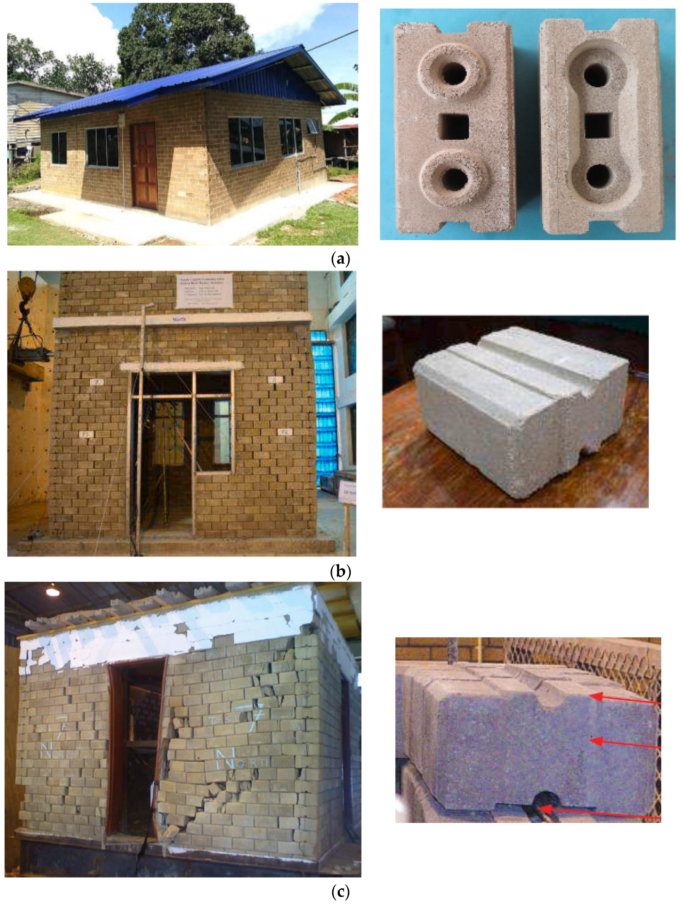
Figure 1. Interlocking structures reported by researchers: (a) Asman et al., [31], (b) Gul et al., [32] and (c) Elvin and Uzeogbo [33].
Buildings 12 02257 g001
Figure 2. Proposed interlocking plastic block: (a) house plan, (b) 3D view, (c) wall assembly, (d) interlocking plastic block for real construction, and (e) cross-section of an interlocking plastic block.
Buildings 12 02257 g002aBuildings 12 02257 g002b
Figure 3. Scaled-down interlocking plastic stretcher block and half block for the current study. (a) Stretcher block. (b) Half block.
Buildings 12 02257 g003
Figure 4. Schematic diagrams of interlocking-plastic-block structural elements.
Buildings 12 02257 g004
Figure 5. Test setups and instrumentation of interlocking-plastic-block structural elements under consideration.
Buildings 12 02257 g005
Figure 6. Failure mechanism of tested interlocking plastic blocks-based structural elements.
Buildings 12 02257 g006
Figure 7. (a) Load–displacement and (b) stress–strain curves of all tested structural elements.
Buildings 12 02257 g007
Table 1. Interlocking-plastic-block structural elements’ labels.
Sr. No.Interlocking Plastic Block Structural ElementsLabel
1One-Block-Wide ColumnPsc
2Two-Block-Wide ColumnPdc
3One-Block-Wide Solid WallPssw
4Two-Block-Wide Solid WallPdsw
5One-Block-Wide Wall With Door OpeningPswo
6Two-Block-Wide Wall With Door OpeningPdwo
Table 2. Experimental energy absorption and toughness index values of interlocking-plastic-block structural elements.
Sr. NoStructural ElementPeak
Load kN
Stress σ
MPa
Strain
ε (10−3)
Modulus of Elasticity
GPa
Energy
Absorbed
Upto Peak Load
(E1) (10−3 Nm)
Energy
Absorbed
after
Peak Load
(E2) (10−3 Nm)
Total
Energy
Absorbed
(ET) (10−3 Nm)
Toughness
Index
(TI)
(ET/E1)
1One-Block-Wide Column1.33.851.7176.6744.810.245.061.05
2Two-Block-Wide Column2.82.2832.1120.69413.7142.3556.074.09
3One-Block-Wide Solid Wall4.10.945722.2796.1823.4229.614.79
4Two-Block-Wide Solid Wall11.71.3668.313.55226.3219.2245.551.73
5One-Block-Wide Wall With Opening1.10.3920.137.6751.263.835.114.02
6Two-Block-Wide Wall With Opening3.70.682.418.8377.5424.1231.674.20
Table 3. Correlation between the load carrying capacities of one and two-block-wide structural elements.
Sr. No.Structural ElementCorrelationIn Terms of
1Two-Block-Wide ColumnOne-Block-Wide ColumnPdc = 2.2 Psc
2One-Block-Wide Solid WallOne-Block-Wide Solid WallPdsw = 2.9 Pssw
3Two-Block-Wide Wall with OpeningOne-Block-Wide Wall with OpeningPdwo = 3.5 Pswo
Table 4. Correlation between load carrying capacity of solid walls and walls with door opening.
Sr. No.Structural ElementCorrelationIn Terms of
1One-Block-Wide Solid WallOne-Block-Wide Wall with OpeningPssw = 3.8 Pswo
2Two-Block-Wide Solid WallTwo-Block-Wide Wall with OpeningPdsw = 3.2 Pdwo
Publisher’s Note: MDPI stays neutral with regard to jurisdictional claims in published maps and institutional affiliations.