Article

Flexural Performance of RC Beams Strengthened with Pre-Stressed Iron-Based Shape Memory Alloy (Fe-SMA) Bars: Numerical Study

1
Ph.D. Program in Material Science and Engineering, College of Arts and Sciences in Collaboration with College of Engineering, American University of Sharjah, Sharjah P.O. Box 26666, United Arab Emirates
2
Structural Engineering Department, Faculty of Engineering, Tanta University, Tanta P.O. Box 31733, Egypt
3
Department of Mechanical Engineering, American University of Sharjah, Sharjah P.O. Box 26666, United Arab Emirates
4
Department of Civil Engineering, American University of Sharjah, Sharjah P.O. Box 26666, United Arab Emirates
*
Author to whom correspondence should be addressed.
Buildings 2022, 12(12), 2228; https://doi.org/10.3390/buildings12122228
Submission received: 11 October 2022 / Revised: 23 November 2022 / Accepted: 30 November 2022 / Published: 14 December 2022
(This article belongs to the Section Building Materials, and Repair & Renovation)

Abstract

:
The iron-based shape memory alloy (Fe-SMA) has promising applications in strengthening and repairing aged steel-reinforced concrete structural elements. Fe-SMA bars can produce pre-stressing forces on reinforced concrete members by activating their shape memory phenomenon upon heating. This study aims to numerically evaluate the impact of pre-stressed Fe-SMA bars on the structural behavior of reinforced concrete (RC) beams at the serviceability and ultimate stages. Nonlinear finite element (FE) models were developed to predict the response of RC beams externally strengthened with Fe-SMAs. The model shows to correlate well with published experimental results. A parametric investigation was also carried out to examine the effect of various concrete grades, pre-stressing levels, and Fe-SMA bars’ diameter on load-deflection behavior. In light of the innovative nature of the Fe-SMA strengthening technique, a comparison investigation was established between RC beams strengthened with Fe-SMA bars against different pre-stressing systems, such as carbon fiber reinforced polymer (CFRP) bars, glass fiber reinforced polymer (GFRP) bars, and steel strands. The numerical findings showed a significant increase in the beams’ load-carrying capacity with larger Fe-SMA bars’ diameter. Specifically, using 12 mm Fe-SMA bars instead of 6 mm increased the beam’s strength by 73%. However, a 14% reduction in ductility was recorded for that case. Moreover, the pre-stressing level of Fe-SMA bars and concrete grade showed a negligible effect on the ultimate strength of the examined beams. Moreover, increasing the pre-stressing level and concrete strength significantly enhanced the load-deflection response in the serviceability stage. Furthermore, using 2T22 mm of Fe-SMA bars resulted in a better structural performance of RC beams compared to other techniques with 2T12 mm, with a comparable cost. Thus, it can be concluded that using Fe-SMA bars embedded in a shotcrete layer attached to the beam’s soffit is a viable and promising strengthening strategy. Nevertheless, further experimental investigations are recommended to further ascertain the reported findings of this numerical investigation.

Graphical Abstract

1. Introduction

Strengthening reinforced concrete structures has a high potential to increase the structure’s life span. Recently, several strengthening techniques have been used extensively by researchers. Aksoylu et al. reported a novel strengthening technique for restoring the shear capacity of RC beams with web openings [1]. These authors found that the anchors exhibited a 38% reduction in the initial stiffness of the test beams. Gemi et al. studied the effect of various types of fiber wrapping on the behavior of RC beams [2]. The experimental results showed that carbon wrapping is more beneficial than glass wrapping in load-carrying capacity. Khalil et al. [3,4,5] demonstrated the effectiveness of strengthening existing reinforced concrete beams using high-performance strain-hardening cementitious composites (UHP-SHCC). Additionally, they recommended using reinforcement in the soffit additional layer to enhance crack distributions and avoid localized failure. This strengthening technique, however, is reported to be costly. Peng et al. [6] investigated the flexural performance of RC beams strengthened with cementitious grout. The test results revealed that strengthened beams could attain closer performance to conventional RC beams, which concluded the efficiency of the proposed technique. Hawileh et al. [7,8,9] examined the effects of using different strengthening techniques on ultimate capacity and ductility. Their results showed that fiber-reinforced polymer (FRP) materials enhanced the flexural capacity of the beam specimens at the expense of ductility. Sun et al. [10] investigated RC beams strengthened with unbonded pre-stressed FRP bars at the serviceability stage. The authors proposed an approach predicting the number of required bars to satisfy the cracking resistance. Similarly, Su et al. [11] tested RC beams strengthened with near-surface-mounted (NSM) FRP strips. They concluded that the FRP bond length significantly affects the behavior of test specimens. Arslan et al. investigated the shear behavior of RC beams strengthened with FRP sheets [12]. The results exhibited that the best strengthening technique among all test methods is the full wrapping with carbon fiber reinforced polymer (CFRP) and a 45-degree anchorage. Gemi et al. tested under-reinforced concrete beams strengthened with CFRP composites at the shear span [13]. The authors concluded that CFRP composites’ weight and direction are crucial for strengthening such beams. Nie et al. [14] proposed an analytical approach to predict the load-carrying capacity of RC beams with web openings strengthened with FRP. The results showed a good agreement between the proposed technique and previous experiments. Najaf et al. [15] numerically investigated the effect of FRP sheets’ number, direction, and type on the behavior of RC beams strengthened with FRP sheets. The results exhibited that FRP sheets with an inclination angle of 45° had a better performance than that of 60 and 90°. In addition, AlHamaydeh et al. [16,17,18] reported several techniques used to analyze different structural elements under lateral loads. Lateral loads usually cause damage to structural elements, resulting in the need for rehabilitation.
One of the most widely used materials in civil engineering applications is concrete. Several factors, however, can lead to the demise of reinforced concrete (RC) structures over time, including aging, poor RC design, poor material selection, quality, and the development of unexpected loads, i.e., excessive snow-induced steel roof failures in Turkey. Externally bonded reinforcement (EBR) and near-surface-mounted (NSM) techniques are considered substantial methods for strengthening RC members [7,8,9,10,11,12,13,14,15,16,17,18]. Typically, FRP composites strengthen existing structural elements such as RC beams and slabs. The installation of the EBR method entails embedding an FRP composite in a soft layer (adding a concrete layer) that is adhered cohesively to the external surface of the exiting structural element. Alternatively, the NSM method involves cutting grooves in the beam and installing the FRP with mortar. Numerous studies have found that the mechanical properties of FRP composites, such as Young’s modulus (E) and ultimate tensile strength (σult), significantly degrade when exposed to high temperatures [3]. Due to FRP’s limitations, shape memory alloys (SMAs) have been explored as alternative strengthening rebars. Moreover, SMA can exhibit a superelastic response (SE), accommodating significant levels of reversible deformation and/or a shape memory effect (SME) that can be utilized to induce compressive stresses into the strengthened structure members. Accordingly, shape memory alloys (SMAs) are superior strengthening rebars to FRP in terms of structural seismic performance [19,20].
Recent research was conducted by Gahafoori et al. [21] to investigate the structural performance of RC beams strengthened with an iron-based shape memory alloy (Fe-SMA) and carbon fiber-reinforced polymer (CFRP) materials. Gahafoori et al. discussed the mechanical properties, fatigue, creep, corrosion, thermal expansion, high temperature, and behavior in fire exposure of the Fe-SMA compared to CFRP. CFRPs are corrosion-free due to their nonmetallic nature, which explains why, over the last two decades, CFRP reinforcements have succeeded in eliminating corrosion problems associated with conventional steel reinforcements [21]. Indeed, CFRPs might exhibit greater corrosion resistance than Fe-SMAs. Nevertheless, an electrochemical test by Karbhari et al. [22] has shown that the Fe-17Mn-6Si-10Cr-4Ni-1(V, C) SMA exhibits superior corrosion properties over conventional steel, since the Fe-17Mn-6Si-10Cr-4Ni-1(V, C) SMA contains approximately 10% chromium in its chemical composition, which boosts its corrosion resistance [23]. Furthermore, iron-based shape memory alloys (FeMnAlNiTi) demonstrated excellent functional performance recovery, as reported by Sidharth et al. [24].
To the best of the authors’ knowledge, only a few numerical studies have been conducted on RC beams strengthened with the EBR method and pre-stressed with Fe-SMA bars (e.g., [25,26,27]). This study aims to develop a parametric analysis to simulate the flexural behavior of RC beams strengthened with Fe-SMAs by implementing the EBR method. ABAQUS [28] is used to construct a 3D FE model of RC beams with pre-tensioned Fe-SMA bars as the EBR. The model uses a four-point bending configuration to illustrate the behavior of beams being loaded monotonically under static conditions [29]. The concrete damage plasticity (CDP) model was utilized to simulate and predict the nonlinear concrete behavior based on concrete parameters, including concrete compressive strength (fc′). In order to incorporate the change in fc′, as a part of the current parametric study, a concrete constitutive model with different parameters is used, as recommended by Hafezolghorani et al. [30]. Regarding the simulation of the Fe-SMA bars, a step that does not involve any loading is defined in ABAQUS to facilitate self-equilibrium. The simplified model described by Shahverdi et al. [31] for Fe-SMA activation is used in the present study. The ABAQUS implementation of the Fe-SMA model includes an offset in the SMA stress–strain curve in compliance with the recommendation of Shahverdi et al. [31].
A nonlinear finite element (FE) model verification with experimental data is developed in this study for modeling RC beams strengthened with Fe-SMA bars. Load-deflection curves, ultimate loads, and crack patterns are compared. A parametric study is then carried out using the validated model to measure the effects of various parameters on the structural behavior of RC beams pre-stressed with Fe-SMAs. The study includes the effects of varying pre-stressing levels, concrete compressive strength, and the diameter of Fe-SMAs. Furthermore, since Fe-SMA strengthening is characterized by its innovative nature, a comparison investigation is established between RC beams strengthened with Fe-SMA bars versus various pre-stressing systems, including CFRP and GFRP bars and steel strands.

2. Background and Literature

Shape memory alloys (SMAs) were first discovered in 1932 by Ölander [32]. Since then, SMAs have been extensively studied for their shape memory effect (SME) and pseudo-elasticity, which have been deemed as SMA’s main characteristics. SMAs are characterized by the ability to undergo a large deformation while regaining the original shape through a stimulus such as heat (SME) or stress removal (pseudo-elastic). Additionally, SMAs exhibit a superelastic response (SE) that can accommodate large reversible deformations, making them good candidates for concrete reinforcement.
SMAs are now part of a variety of engineering and technical applications, including in composites and structures [33] and aerospace [34,35], robotics [36,37], and biomedical uses [38]. In civil engineering, SMAs are widely used to improve the confinement of self-centering bridge components, dampers, and columns [39]. Researchers have found that Fe-SMAs are a viable alternative to Ni-Ti-based shape memory alloys for several reasons, including their lower production costs, flexibility, wider thermal hysteresis, and higher recovery stress [40,41,42,43,44,45,46]. A permanent SME is the most important structural characteristic of Fe-Mn-Si alloys, enabling them to be used in pre-stressing applications [47,48]. Fe-Mn-Si alloys are unlikely to undergo any further phase changes due to temperature fluctuations after the installation, unlike Ni-Ti-based SMAs that undergo several post-installation phase changes [47]. Moreover, Youssef et al. [20] demonstrated the application of Fe-SMAs to rehabilitate beam–column joints following seismic activity (i.e., earthquake). Several researchers and engineers are currently using Fe-SMAs in pre-stressed flexural strengthening applications in the civil engineering field [20,31,49,50,51,52].
An experimental study by Michels et al. [45] investigated the flexure response of RC beams strengthened with Fe-SMAs using EBR. In their study, Fe-SMA-reinforced beams were compared to CFRP-reinforced beams. Michels et al. [45] found that Fe-SMA-reinforced beams exhibit significantly higher crack loads and ductility than CFRP-reinforced beams. Several factors led to the superiority of pre-stressing Fe-SMA over CFRP; first, CFRP reinforcement must be treated carefully to take advantage of its high tensile capacity and prevent brittle failure. Second, the ultimate strength and Young’s CFRP modulus dramatically decrease at elevated temperatures, whereas Fe-SMAs exhibit exemplary behavior when subjected to high temperatures. Moreover, the pre-stressing application of CFRPs is more complicated and time-consuming than thermally activated (pre-stressed) Fe-SMA rebars. Due to the abovementioned reasons, the Fe-SMA is more likely to be used in pre-stressing.
An experimental study by Shahverdi et al. [46] determined the mechanical properties and recovery properties of the alloy Fe-17Mn-5Si-10Cr-4Ni-1(V, C) (mass%). They concluded that the Fe-SMA has high tensile strength, good shape recovery stress (pre-stress force), and high elastic stiffness [46]. They also studied the effect of pretraining and the maximum heating temperature on the recovery stress. The Fe-SMA showed recovery stress of 300 to 350 MPa when heated to 160 °C, whereas 400 °C is the maximum temperature at which the Fe-SMA will exhibit a 450 MPa recovery stress [46]. Moreover, Shahverdi et al. [46] reported that iron-based SMA (Fe-SMA) is more cost-effective and accessible than Ni-Ti alloys for applications in civil engineering structures.
An experimental study by Zuaiter et al. [53] examined slag/fly ash blended geopolymer concrete’s fresh, mechanical, and durability characteristics. Different types and combinations of glass fibers are added to strengthen the so-produced concrete. The results of Zuaiter et al. indicate that concrete containing hybrid glass fibers can exhibit superior mechanical properties [54]. A computational study by [9] investigated the behavior of reinforced NSM FRP beams using bond-slip models and interface elements in ANSYS. His model considers nonlinear concrete behavior in tension and compression, cohesion between epoxy and concrete, and adhesive cracking. Combining numerical and experimental approaches, Alkhraisha et al. [55] studied the serviceability and flexural capacities of reinforced concrete beams subjected to harsh conditions. Their tests showed that an increase in the reinforcement ratio did not directly increase the RC beam’s moment capacity [55].
Although numerous numerical studies have been conducted on FRP-reinforced beams, there have been very few investigations on Fe-SMA-reinforced RC beams [25,26,56,57,58,59,60]. Furthermore, according to the available literature, Fe-SMA-reinforced RC beams have been extensively investigated experimentally rather than numerically. Recently, Rojob and El-Hacha [52] studied the behavior of concrete beams reinforced with smooth Fe-SMA bars using NSM. Rojob and El-Hacha [52] compared the performance of reinforced RC beams strengthened with a FRP versus Fe-SMA. As compared with pre-stressed FRP, the Fe-SMA demonstrated better yielding and ultimate load capacity [52]. Furthermore, the Fe-SMA material had excellent yield properties, which helped improve the ductility of the beam [52]. Other studies investigated the effect of using Fe-SMA bars as the main reinforcement in beams [61,62]. They concluded that the SMA-reinforced beams exhibited similar performance to steel-reinforced beams. Moreover, the activation of the Fe-SMA pre-stressing effect has a negligible effect on the ultimate load of test beams. Qian et al. combined the effect of Fe-SMA and ECC matrix to strengthen the existing RC beams. The results showed that strengthening beams with Fe-SMA bars embedded in the ECC layer enhanced the self-recovery capacity and ductility [63].
More recently, Yeon et al. [26] evaluated the flexural behavior of RC members reinforced with Fe-SMA bars numerically and experimentally using the EBR technique. The Fe-SMA bars’ pre-stressing effect was slightly overestimated in FE simulations compared to the experimental results [26]. Their FE simulations predicted bending loads 20–30 kN greater than those obtained in the physical experiments [26]. Because the FE simulations are based on highly idealized assumptions of perfect bonding, their experiments showed slips at interfaces contrary to the assumptions made in the FE simulations.

3. Finite Element Simulation

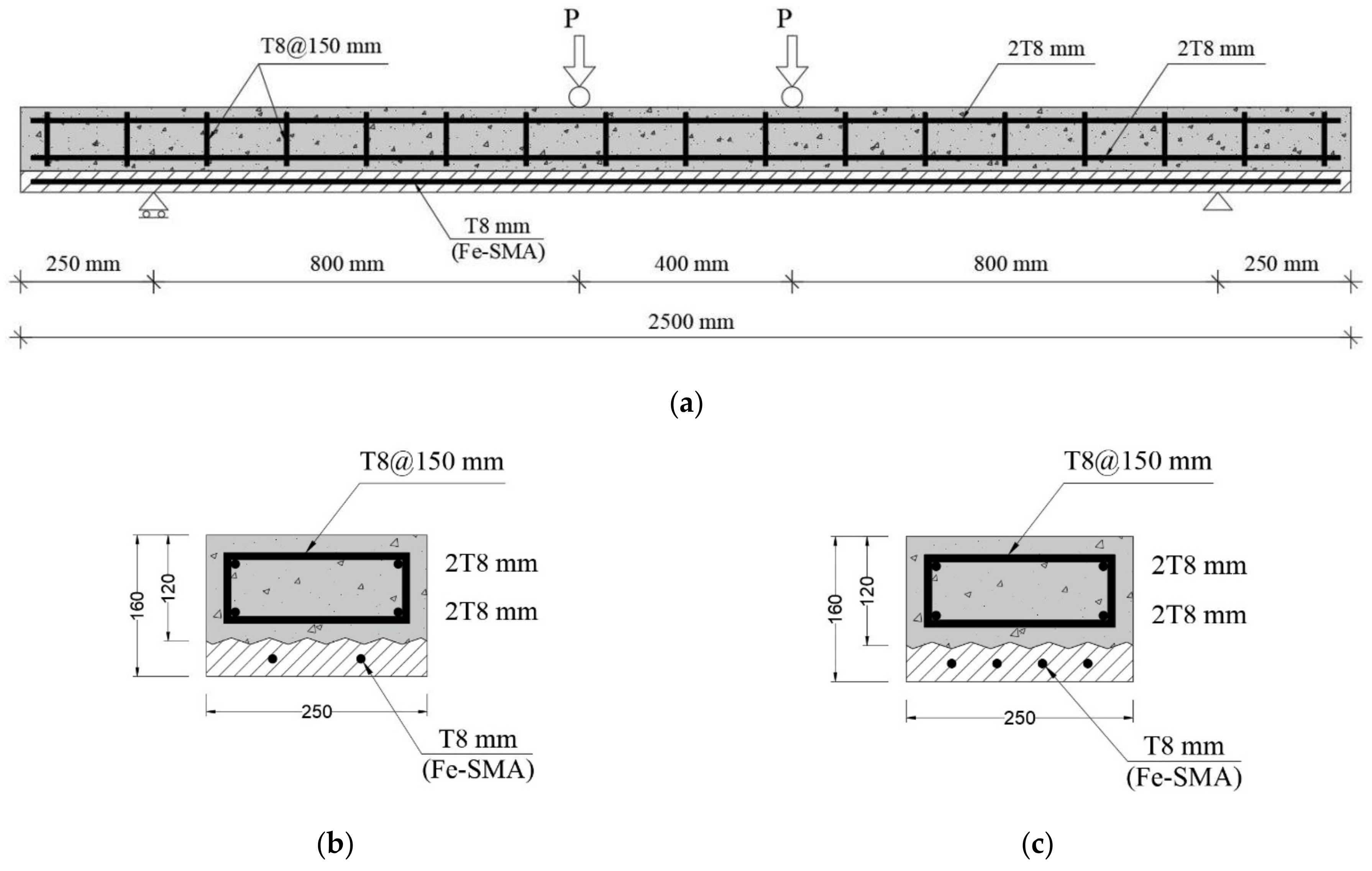
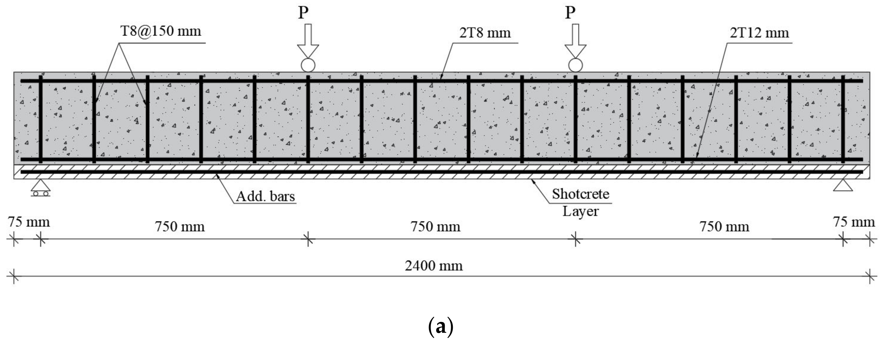
3.1. Beam Geometry Used in Verification

An experiment performed by Shahverdi et al. [31] is compared with the proposed FE modeling to verify its accuracy. Figure 1 summarizes the details of tested beam specimens. ABAQUS software simulates the monotonic loading of the two beams subjected to a four-point bending scheme. The experimental data included two rectangular RC beams with an identical cross-section (120 × 250 mm), clear span length (2000 mm), depth of the soffit (shotcrete) layer (40 mm), and diameter of the strengthening bars (T8 mm). The first beam (B10) is strengthened with two Fe-SMA rebars, while four Fe-SMA rebars are used in the second beam (B11), as shown in Figure 1b,c.

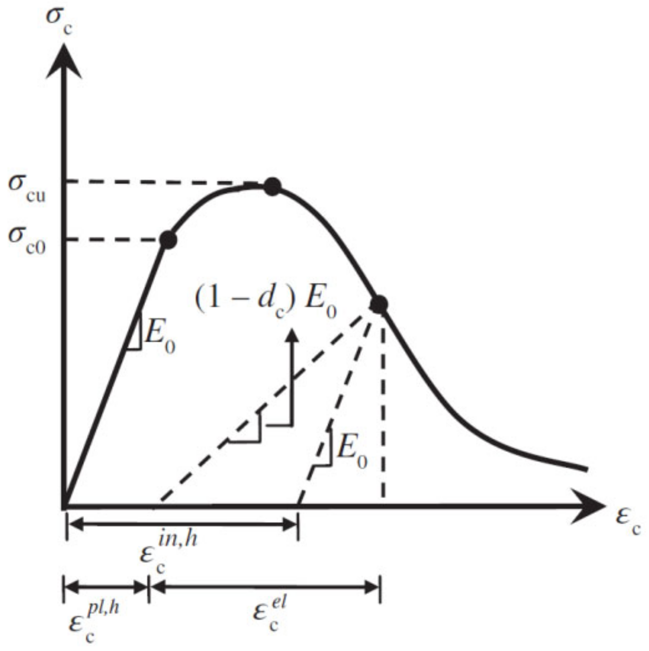
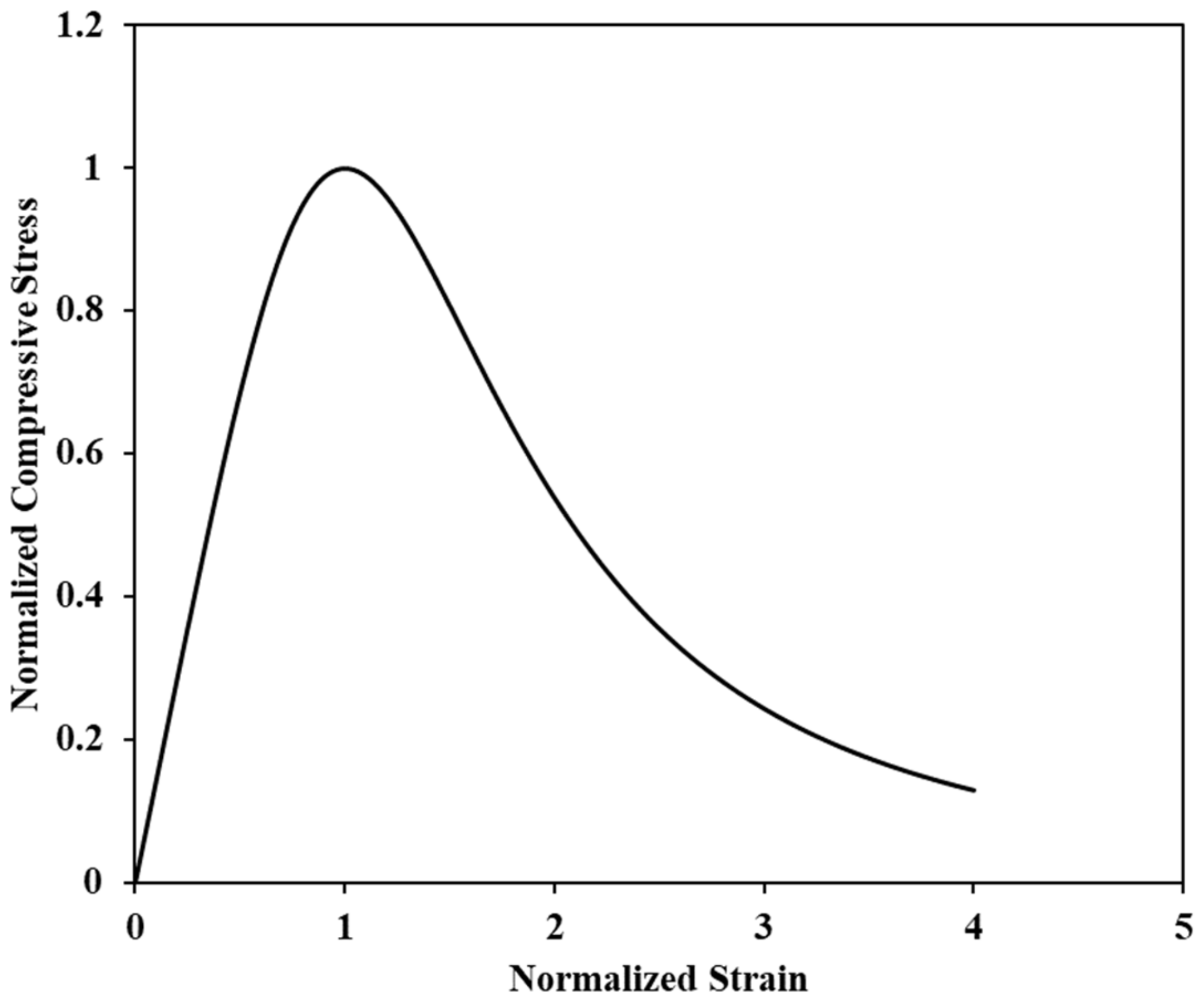
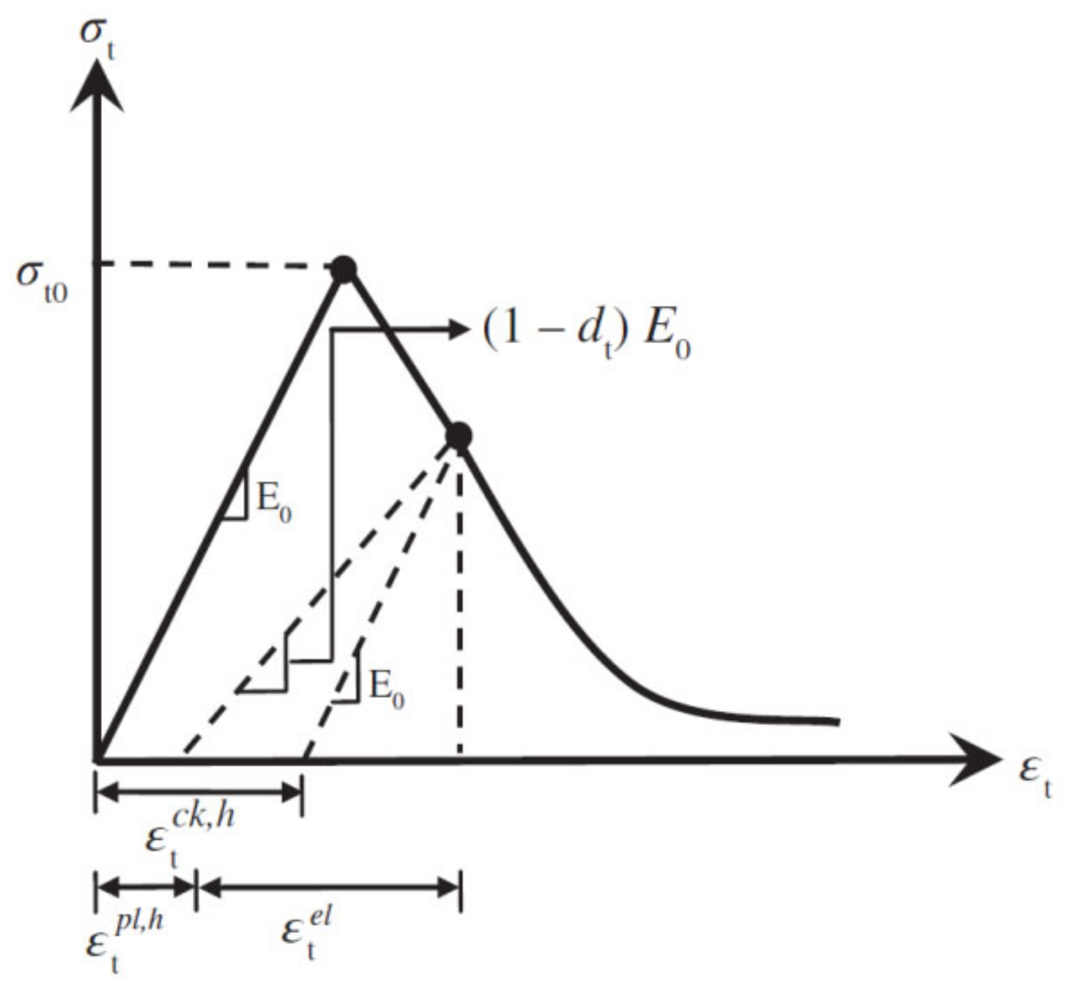
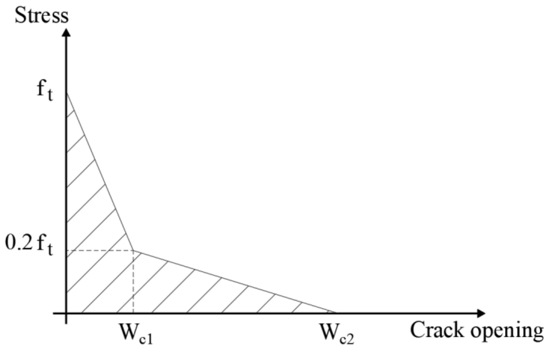
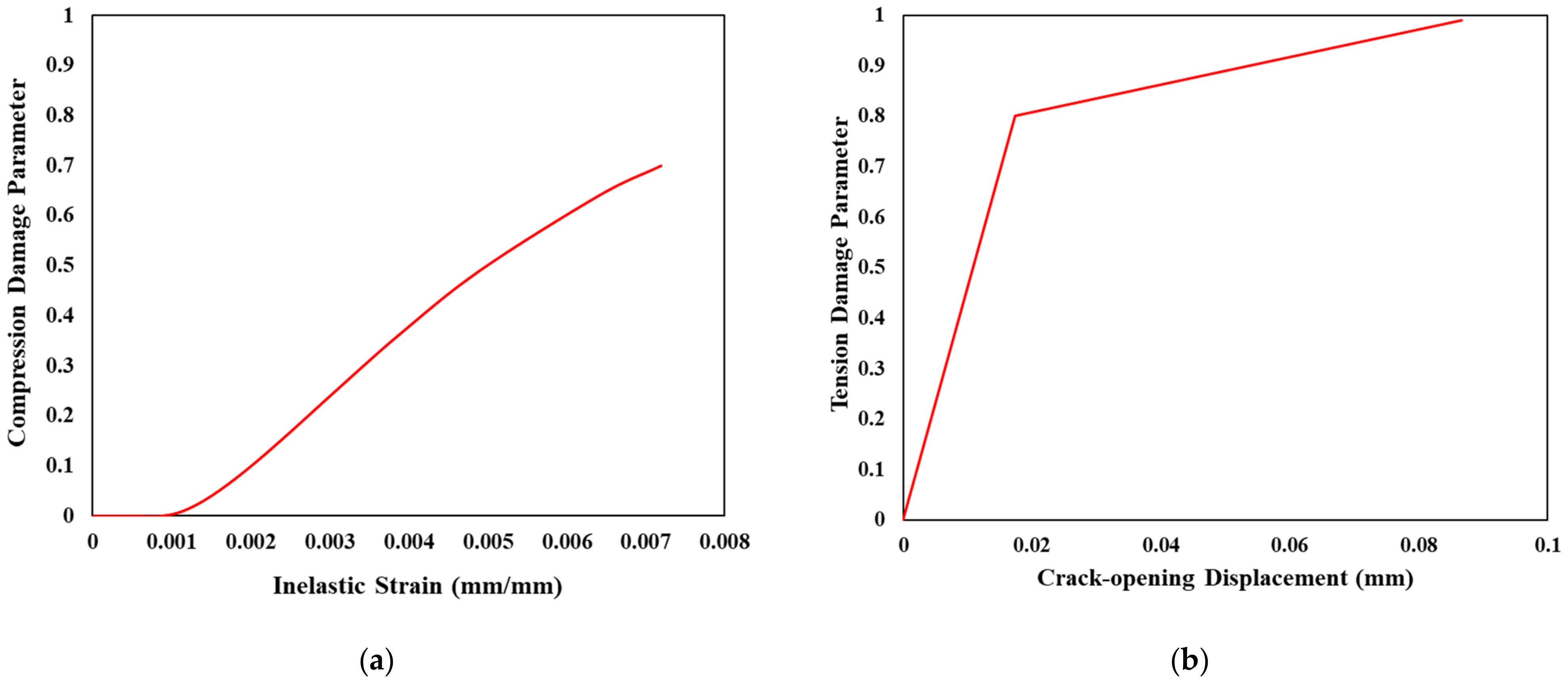
3.2. Constitutive Model for Concrete in ABAQUS

In general, ABAQUS offers three main models to describe the behavior of the modeled concrete in the FE software: concrete damage plasticity, brittle cracking, and smeared cracking. The brittle cracking model usually defines concrete behavior after the cracking stage. Typically, this model is used when tensile cracking dominates the behavior of a concrete element, but it does not incorporate compressive crushing. The smeared crack model simulates crack initiation and propagation by incorporating a multi-directional fixed approach. However, it often suffers from stress accumulating or other numerical issues that lead to convergence problems [52]. On the other hand, concrete damage plasticity (CDP) is a comprehensive model that considers tensile cracking and compressive crushing. Indeed, the analysis includes both concrete tension and compression damages; hence, the CDP is chosen to model the concrete’s behavior in this study.
In this study, the plasticity parameters summarized in Table 1 are used. The dilation angle and viscosity parameters are determined based on a sensitivity analysis conducted by the authors, whereas the remaining parameters are taken as recommended by other research studies [64,65,66,67]. These parameters are used for all concrete grades. Specifically, the dilation angle represents the concrete ductility and is defined as the ratio of volume to shear strains. The range of dilation angles is specified by several studies (15–56°) [68,69,70]. Hence, based on a sensitivity analysis, a value of 55 is adopted in the current study. The eccentricity (e) indicates the plastic potential eccentricity and is taken equal to 0.1. The fb0/fc0 refers to the ratio of the initial equibiaxial to the uniaxial compressive strengths. The recommended value is set to 1.16. The k factor refers to the shape of the loading surface and is taken as 0.67. Furthermore, the viscosity parameter can be used to ascertain the convergence of the numerical solution. However, several researchers recommended a value of 0.0001 [71,72,73].
The CDP model is adequate for defining the concrete material’s behavior, especially at the post-cracking stage. However, it only considers elastic behavior during compression loading to avoid the complications caused by plastic behavior. As the name implies, the CDP model relies on damage and plasticity, which engage the variation in the elastic stiffness and the irreversible deformation into the software ABAQUS [74]. Since the CDP model accounts for damage during tension and compression, the irreversible damage is defined through a flow rule irrelevant to the variable hardening plasticity and a scalar isotropic damaged elasticity [75]. Furthermore, the CDP model consists of various parameters to calibrate the concrete behavior while maintaining the model’s accuracy. In the CDP model, the relationship between the compressive strength of concrete and damage parameters is determined by the plastic hardening strain, as shown in Figure 2. It is noteworthy that the shotcrete layer and the concrete of the beam are defined using the same constitutive models.
Equations (1)–(3) summarize the derivation of the plastic hardening strain in compression, according to the CDP model:
σ c = 1 d c E 0 ε c ε c p I , h
ε c i n , h = ε c σ c E 0 ε c p I , h = ε c σ c E 0 1 1 d c
ε c p I , h = ε c i n , h d c 1 d c σ c E 0
where σ c and ε c   are the compressive stress and strain, respectively, E 0 is the modulus of elasticity, d c is the compressive damage parameter, ε c i n , h and ε c p I , h are inelastic and plastic hardening strain in compression, respectively, and σ c u and σ c 0 , shown in Figure 2, are the compressive stress at peak and the initial yield of concrete, respectively.
Experimental or constitutive models can characterize the concrete stress–strain relationship under uniaxial compression. In general, several renowned constitutive models are usually utilized in this regard, such as the constitutive model proposed by Hognestad [76], Kent and Park [77], and Hsu et al. [78]. Furthermore, Mier et al. [66] studied the softening behavior of concrete under several test parameters (e.g., aspect ratio and loading direction). Moreover, they reported that the post-peak behavior of concrete depends on the crack pattern and failure mode of test specimens. In this study, the stress–strain relationship proposed by Hsu et al. [78] is used, demonstrated in Figure 3 and Equations (4)–(7). It is worth mentioning that Figure 2 describes the relationship between the concrete response under compression and the damaged parameters defined for the CDP model, as mentioned in the ABAQUS manual [79], while Figure 3 defines the adopted compressive stress–strain relationship of concrete in the current study according to the constitutive model mentioned in Hsu et al.’s study [78].
  η = n β x n β 1 + x n β                           f o r   0 x < x d
where
η = f c f c '
x = ϵ ϵ 0
β = 1 1 f c ' / ϵ 0 E i t                           f o r   β 1
where η is the normalized stress, f c and ϵ are the stress and strain in general, respectively, β and n are material parameters ( β depends on the stress–strain diagram’s shape, while n is determined by the material’s strength), x is the normalized strain, x d is the strain at 0.3 f c ' , f c ' is the concrete stress peak, ϵ 0 is the corresponding strain to stress peak, and E i t is the initial tangential modulus. Hsu et al. [78] reported analytical expressions that can be used to determine the parameters in Equation (4), as follows:
E i t = 1.2431 × 10 2   f c + 3.28312 × 10 3
ε o = ( 8.9 × 10 5 )   f c + 2.114 × 10 3
n = 1.0         f o r   0 < f c < 62   M P a
On the other hand, the plastic hardening strain in tension is derived as part of the CDP models, as described in Figure 4.
The following equations summarize the plastic hardening strain in tension:
σ t = 1 d t E 0 ε t ε t p I , h
ε t c k , h = ε t σ t E 0 ε t p I , h = ε t σ t E 0 1 1 d t
ε t p I , h = ε t c k , h d t 1 d t σ t E 0
where σ t and ε t   are the general tensile stress and strain, respectively, and d t is the tensile damage parameter. Moreover, ε t c k , h and ε t p I , h are the cracking and plastic hardening strain in tension, respectively.
In ABAQUS [75], there are typically two ways to define the tension-stiffening behavior of concrete. In other words, the post-cracking tensile behavior of concrete can be evaluated using either the stress–strain relationship or the crack-opening displacement relationship. For instance, Van Mier et al. [80] reported a concrete model considering tension stiffening based on the stress–strain relationship. However, in this study, the crack-opening displacement approach is implemented using the CEB-FIP code [81] to simulate the concrete tensile response. However, minor modifications are implemented in the relationships based on the conducted sensitivity analysis, as demonstrated in Figure 5 and Equations (14)–(18).
f t = 0.33 f c '
G f = G f 0 2 f c ' 10 0.7
G f 0 = 0.0469 D m a x 2 D m a x 2 + 26    
W c 1 = G f f t
W c 2 = 5   G f f t
where f t and G f are the concrete’s tensile strength and fracture energy, respectively, G f 0 is the factor that accounts for the maximum aggregate size ( D m a x ), W c 1 is the crack width at 0.2 f t , and W c 2   represents the maximum crack width.
According to Hafezolghorani et al. [30], compression (dc) and tension (dt) damages were also incorporated in this study to simulate the degradation response while concrete crushing and cracking, respectively, as shown in Figure 6. The compressive and tensile damage parameters are defined as the ratio of the inelastic strain to the total strain and the cracking strain to the total strain, respectively.
The damage parameters of compression ( d c ) and tension ( d t ) are calculated as functions of the compression stress ( σ c ) and tension stress ( σ t ), respectively, as follows:
d c = 1 σ c σ c u
d t = 1 σ t σ t 0
where σ c u and σ t 0 are the compression and tension stresses at the peak, respectively.

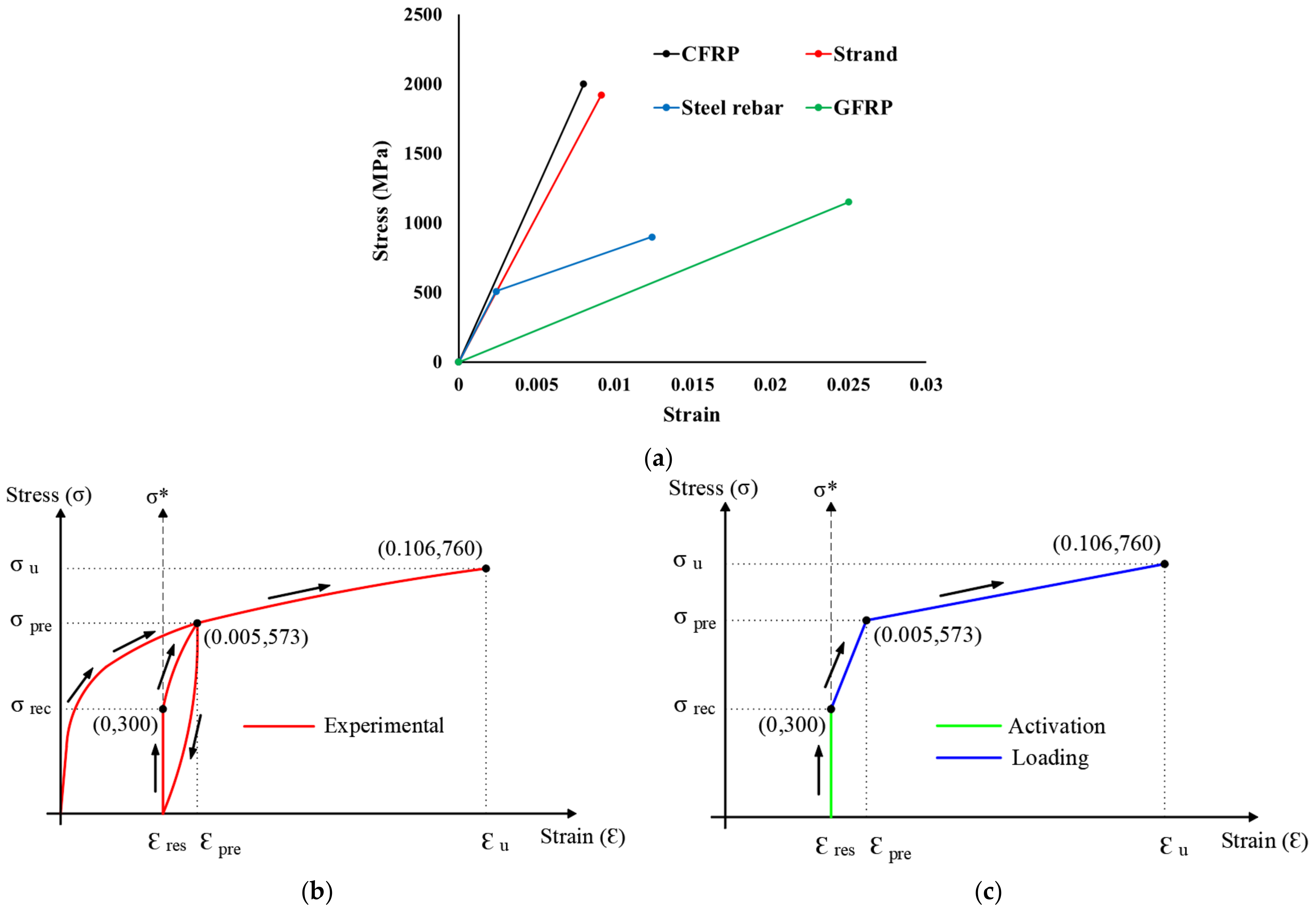
3.3. Reinforcement Definition in ABAQUS

The longitudinal and transversal steel reinforcements are modeled in ABAQUS using a bi-linear stress–strain relationship covering the elastic and plastic regions, as described in Figure 7a. Specifically, an elastic modulus and yield stress of 210 GPa and 508 MPa, respectively, are used to define the steel reinforcement properties [31]. On the other hand, CFRP, GFRP, and steel strands are modeled using a linear stress–strain relationship, since such materials usually experience no yielding behavior. The CFRP and GFRP products have a modulus of elasticity of 250 GPa and 46 GPa, and rupture stress of 2000 MPa and 1150 MPa, respectively [82]. Furthermore, the 7-wire steel strand of 12.7 mm diameter has a modulus of elasticity of 210 GPa and ultimate strength of 1918 MPa [83]. Figure 7a shows each material’s stress–strain relationship defined in ABAQUS. It is worth noting that ABAQUS allows users to simulate the pre-stressing effect through defining an initial stress value in the predefined field in a separate loading step, as described in more detail in Section 3.4.2. This approach is adopted to define all pre-stressing techniques in this study.
The experimentally obtained elastic modulus of 133 GPa paired with a Poisson’s ratio of 0.3 is defined in ABAQUS to simulate the elastic behavior of Fe-SMA bars [31]. The Fe-SMA strengthening rebars contain iron, manganese, silicon, chromium, and nickel with chemical compositions of Fe-17Mn-5Si-10Cr-4Ni-1(V, C) when classified by mass ratio. In the absence of a built-in ABAQUS models for the Fe-SMA, an experimental stress–strain curve from Shahverdi et al. [31] is used to simulate the structural behavior of Fe-SMA, as shown in Figure 7b. The recovery stress is defined under the predefined field in ABAQUS to simulate the pre-stressing effect. A quite similar stress–strain curve to the adopted one in this study was used in a study by Hong et al. [56]. Figure 7b demonstrates that the tensile force is removed after the rebars are stretched to a specified pre-strain value (εpre). Meanwhile, the elastic and pseudo-elastic strains are restored, resulting in a residual strain (εres). In ABAQUS, Fe-SMA rebar is initially defined using recovery stress (σrec), as identified by the green line in Figure 7c, simulating the activation by a heating system. In the experimental study conducted by Shahverdi et al. [31], copper clamps are used at the end of each Fe-SMA bar to facilitate electrical current flow, hence producing the heat required to activate the Fe-SMA. The aforementioned activation mechanism used by Shahverdi et al. [31] is used to activate Fe-SMA bars in this study. Furthermore, the blue curve in that figure represents the tensile stress applied again to the Fe-SMA rebar after loading the beam. During the loading stage, the stress–strain curve (blue curve) is very similar to the one obtained experimentally (red curve). Nevertheless, the first has a horizontal strain shift and a vertical stress shift that match the residual strain (εpre) and recovery stress (σrec), respectively.

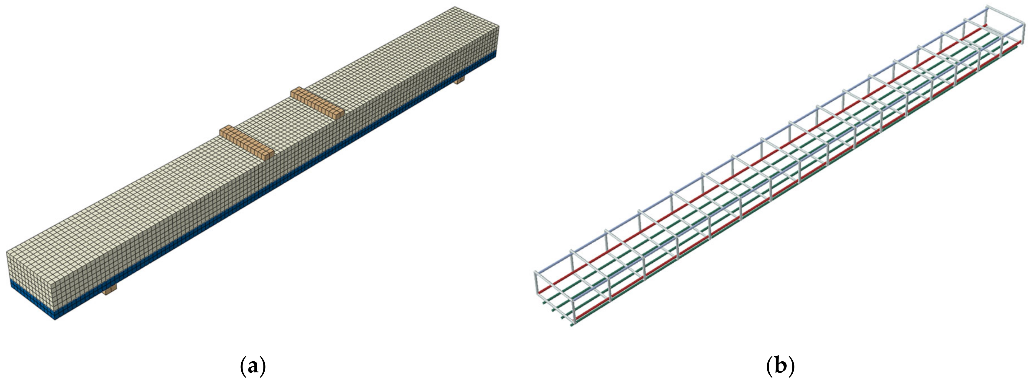
3.4. RC Beam Modeling in ABAQUS

This study uses ABAQUS to develop three-dimensional FE models (3D FEM) to simulate the RC beam’s behavior under monotonic loading. All beam parts, including concrete, shotcrete (the additional concrete layer), steel reinforcements (main reinforcement and shear reinforcement), Fe-SMA rebars, and steel plates, are defined in the FE software with proper sections and material properties. In order to ensure proper interactions between the concrete and the embedded reinforcement, the rebars are defined as the embedded region, while the concrete is the host region. Similarly, Fe-SMA rebars are selected as embedded regions in the shotcrete layer. Furthermore, a perfect bond between the concrete and embedded bars and the concrete and the shotcrete layer is defined in FEM based on the experimental findings of Shahverdi et al. [31]. The contact surface between the steel plate supports and the concrete beam is simulated in ABAQUS using the Tie constraint, considering the fully bonded behavior.

3.4.1. Elements and Meshing

The concrete and shotcrete layer were modeled in ABAQUS using brick elements with eight nodes (C3D8R), as shown in Figure 8a. The adopted C3D8R element was defined with an hourglass-controlled and reduced integration. The hourglass control approach is an enhanced method that does not require any scaling factor, since it considers stiffness coefficients based on the improved strain method. The reduced integration speeds up the numerical solution by solving the integral using the minimum number of Gaussian coordinates. On the other hand, a two-node linear 3D truss element (T3D2) was used to simulate the reinforcement, which can accurately account for the bars’ axial stiffness, as depicted in Figure 8b. Furthermore, the steel plates were defined using the same criteria for the concrete and the shotcrete layer. Each node in the model involves three degrees of freedom (x-y-z displacements). In order to ensure a good accuracy of the results and avoid convergence problems during the solution, a small element size of 20 mm has been utilized for all beam parts.

3.4.2. Pre-Stressing Modeling

The present parametric study considers four pre-stressing levels, Pi (recovery stresses): 0% (0 MPa), 20% (150MPa), 40% (300 MPa), and 60% (450 MPa). The pre-stressing level indicates the percentage of the recovery stress to the ultimate stress of the Fe-SMA bar. Each recovery stress is defined in the predefined field under the loading section in ABAQUS. This option allows the users to input the required recovery stress needed to enforce the rebars in the axial direction. Subsequently, to simulate the actual condition of the pre-stressing approach, represented by upward beam deflection, an initial step without any loading is defined to allow the beam self-equilibrium and to visualize the pre-stressing effect, as shown in Figure 9. This approach is adopted to define all pre-stressing techniques in this study. Moreover, in order to verify the pre-stressing definition step in ABAQUS, the maximum upward deflection at midspan is numerically calculated for the beam (11) with a recovery stress of 300 MPa (Figure 9) and then compared to the theoretical value. The theoretical value is determined based on the structural mechanics’ basics, as demonstrated in Equation (21). The external applied pre-stressing forces can be represented by a concentrated bending moment at the two ends of the beam. This bending moment equals the pre-stressing recovery force in each Fe-SMA bar multiplied by the eccentricity from the cross-sectional centroid. The pre-stressing recovery force can be determined by multiplying the recovery stress (300 MPa) by the area of Fe-SMA bars. The analytical and numerical results show closer values with an average difference of 3%, which ensures this step’s validation in ABAQUS.
δ = M × L 2 8 × E × I = 300 × 50.3 × 4 × 60 × 2000 2 8 × 32562 × 85333333 = 0.65   mm
where   M is the external bending moment applied at the two beam ends, L is the loaded beam length, E is the concrete elastic modulus, and I is the moment of inertia.

4. Parametric Study

After validation of the FE modeling, parametric investigations were carried out to study the effect of the different parameters on the structural behavior of the RC beams using the FE software ABAQUS. The effect of bar diameter (T6, T8, T10, and T12 mm), concrete compressive strength (30, 40, 50, and 60 MPa), pre-stressing level (0, 20, 40, 60%), and strengthening material type (FRPs, Fe-SMAs, and steel strands) on the structural performance of the pre-stressed RC beam are addressed. Figure 10a exhibits the adopted four-point loading test setup. Figure 10b–e show that all beams are reinforced with two steel bars with a diameter of 8 mm on the compression side and two steel bars of 12 mm in diameter on the tension side. Furthermore, the strengthening bars are attached to the beam through a 40 mm shotcrete layer at the bottom of the beam, as shown in Figure 10. Specifically, the control beam is modeled with a plain shotcrete layer, whereas the pre-stressed, Reference 1, and Reference 2 beams are strengthened with two bars of Fe-SMA, 2T8 mm (steel reinforcement), and 2T12 mm (steel reinforcement), respectively.

5. Results and Discussion

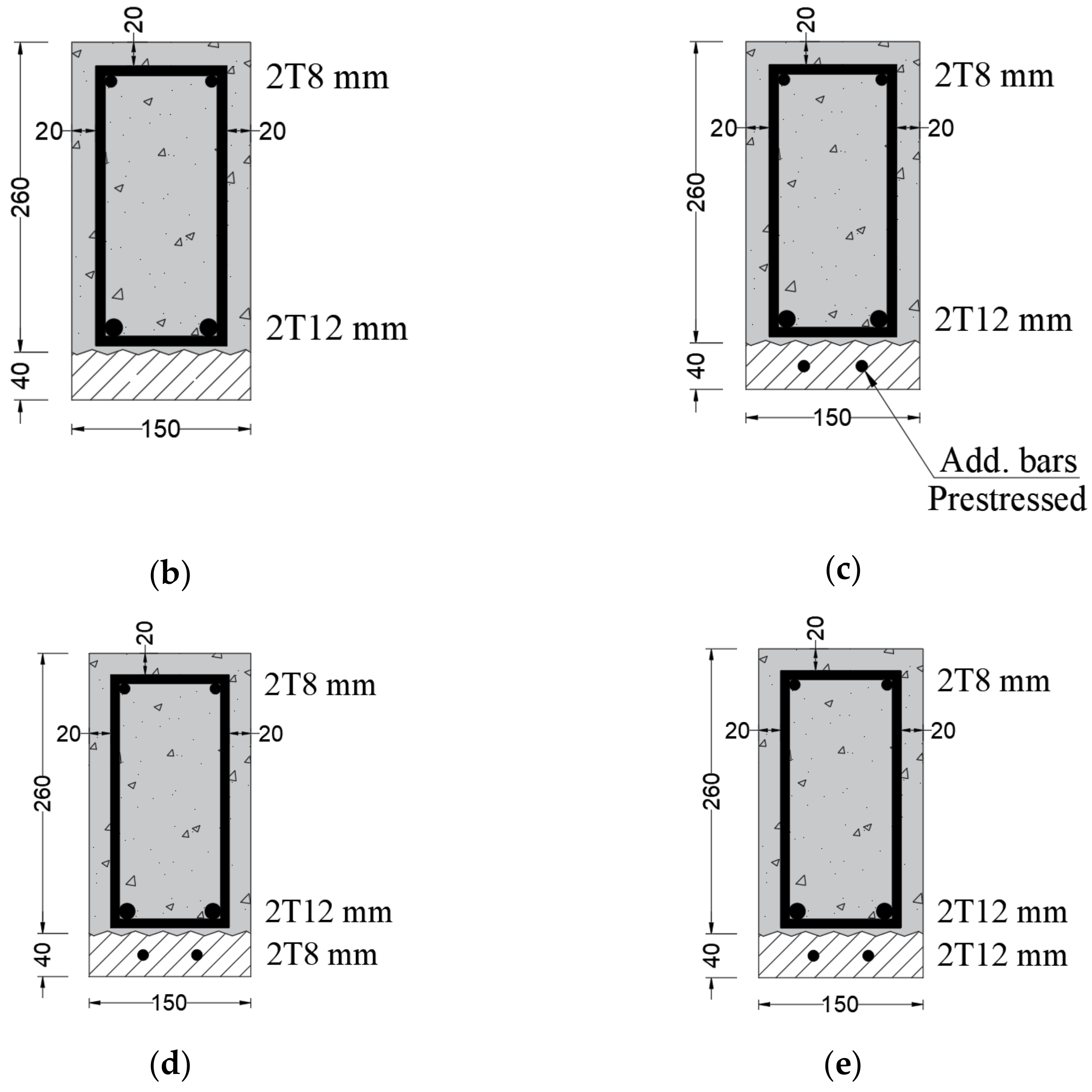
5.1. Verification Models

The FE modeling is validated with the experimental findings of beam 10 and beam 11 from Shahverdi et al.’s work [31]. Figure 11 illustrates the load-deflection response for beams 10 and 11. The load-deflection curves based on FE models are very close to the experimental curves. However, some differences in the initial loading stages can be noticed, which could be attributed to the fact that the numerical solution cannot predict all experimental conditions (e.g., initial thermal microcracks). In addition, the actual experimental conditions do not provide the assumed fully bonded behavior of contact surfaces in the FEA. It is worth noting that the numerical analyses of beams 10 and 11 have been stopped at deflection values close to the maximum deflection observed in the experimental test. Furthermore, the experimental results observed by Shahverdi et al. showed a flexural failure mode for all tested beams (i.e., steel reinforcement yielding followed by concrete crushing at compression). Figure 12 shows the experimental cracking pattern, as mentioned in Shahverdi et al.’s work [31], compared to the numerical results. Similar cracking behavior can be noticed in Figure 12. However, the numerical results show a diffused cracking pattern due to the effect of the viscosity parameter adopted in the study based on the conducted sensitivity analysis, as pointed out previously. This observation agrees with the findings mentioned in Szczecina and Winnicki [73]. Moreover, Figure 12 also shows the von Mises stresses in steel reinforcement at the peak load.

5.2. Parametric Study

In general, FE modeling reduces the cost and duration of design-oriented parametric studies compared to experimental tests. After validating the constitutive and numerical models, the authors decided to expand the experimental work by testing various parameters. However, since the experimental test beams had an unregular shape (i.e., the depth is significantly less than the width), the authors suggested new dimensions for the numerical test beams, simulating the beams in real buildings. Thus, by using valid FE models as a benchmark, a numerical design-oriented parametric study is conducted in this research in order to study the effect of different parameters on the load-deflection response of RC beams strengthened with Fe-SMA bars, as illustrated in the following subsections.

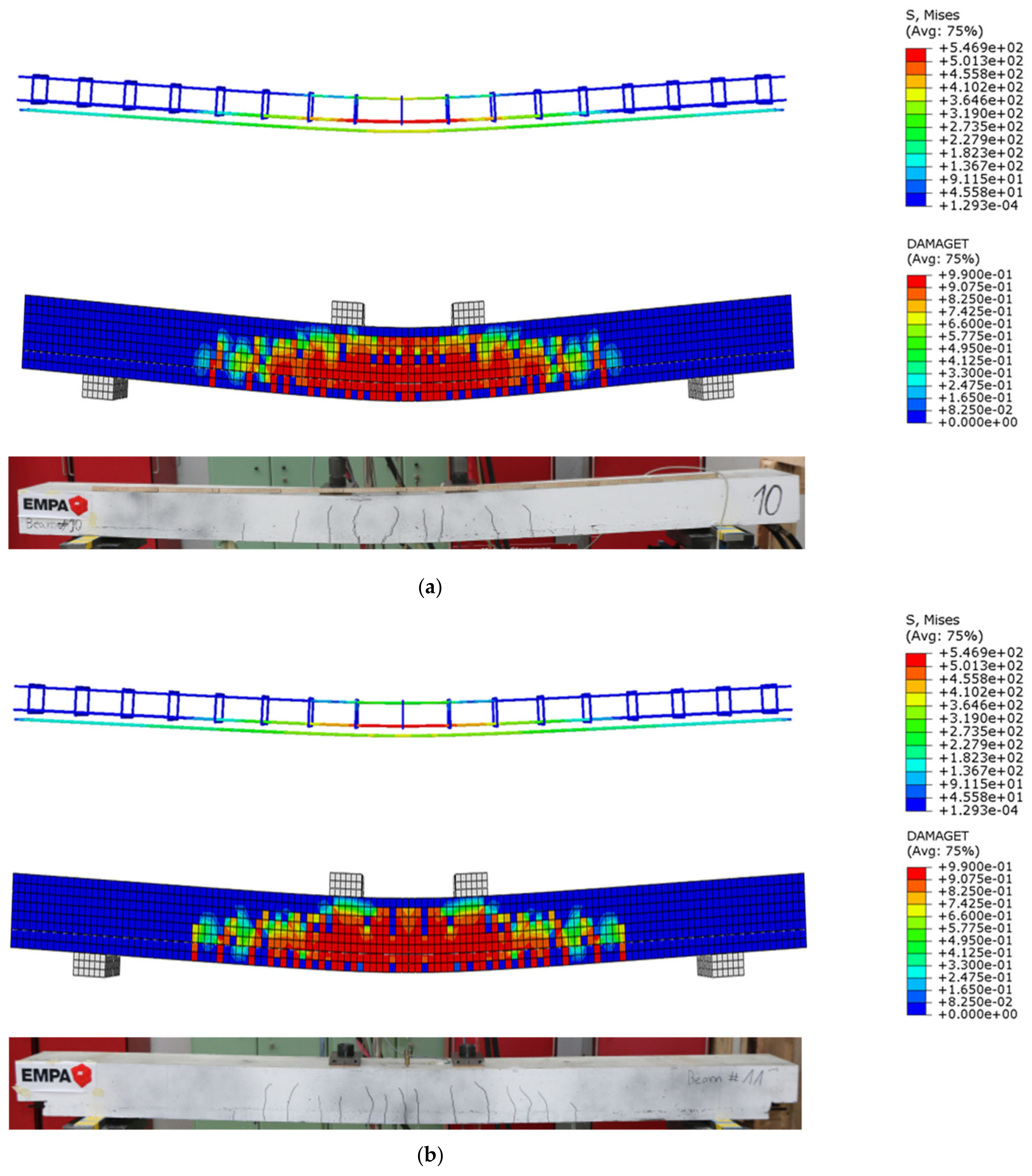
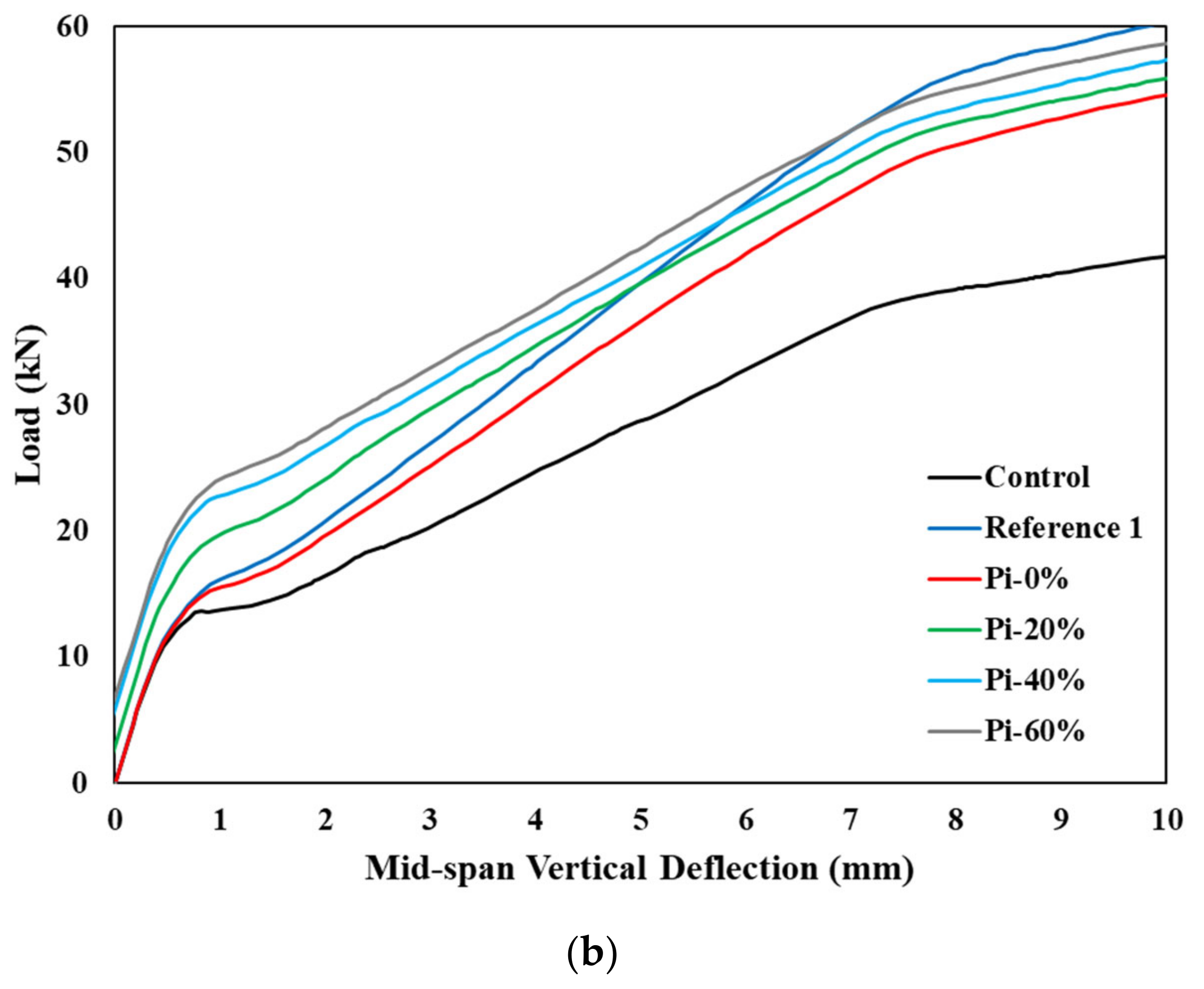
5.2.1. Effect of Pre-Stressing Level

This section investigates the influence of varying the pre-stressing levels on the load-deflection response of RC beams. Figure 13a compares the load-deflection behavior of the control beam, Reference 1, and four pre-stressed beams. The four pre-stressed beams are subjected to a wide range of pre-stressing levels (0, 20, 40, and 60%). The Pi symbol in Figure 13 refers to the pre-stressing level, which is the ratio of the applied recovery stress to the ultimate stress of Fe-SMA bars. Figure 13b shows enlarged load mid-span deflection, which focuses on the initial 10 mm of deflection so that the differences in the service loading stage can be observed easily. It can be seen in Figure 13b that the pre-stressed beam curves lie between the control and reference beam trends. Moreover, the curves show three slopes, each indicating a phase change, where the cracking, yielding, and ultimate loads are indicated at each transition point. The results of the control and the Reference 1 beams show a slight difference in the cracking load at approximately 14 kN; however, yielding and ultimate loads significantly differ. Due to the relatively higher mechanical properties of steel rebars, the Reference 1 beam exhibits a significant increase of approximately 45% and 43% in yielding and ultimate loads, respectively, compared to the control beam. Similarly, beams strengthened with Fe-SMA bars show a higher load-carrying capacity than the control beam by about 29%. It is noteworthy that the Reference 1 beam achieves higher strength than pre-stressed beams, since steel bars’ yield and ultimate stresses are higher than Fe-SMA bars. All pre-stressed beams show almost identical ultimate loads and minor changes in yielding loads.
In contrast, increasing the pre-stressing level from 0 to 60% results in an increase of approximately 60% in cracking load, indicating the significant effect of the pre-stressing level on the serviceability stage in contrast to the ultimate stage. Additionally, all pre-stressed beams show higher cracking loads than the Reference 1 beam, while the opposite is observed at the ultimate stage. The reason is that the activation of Fe-SMA recovery stress does not significantly increase the ultimate load capacity.

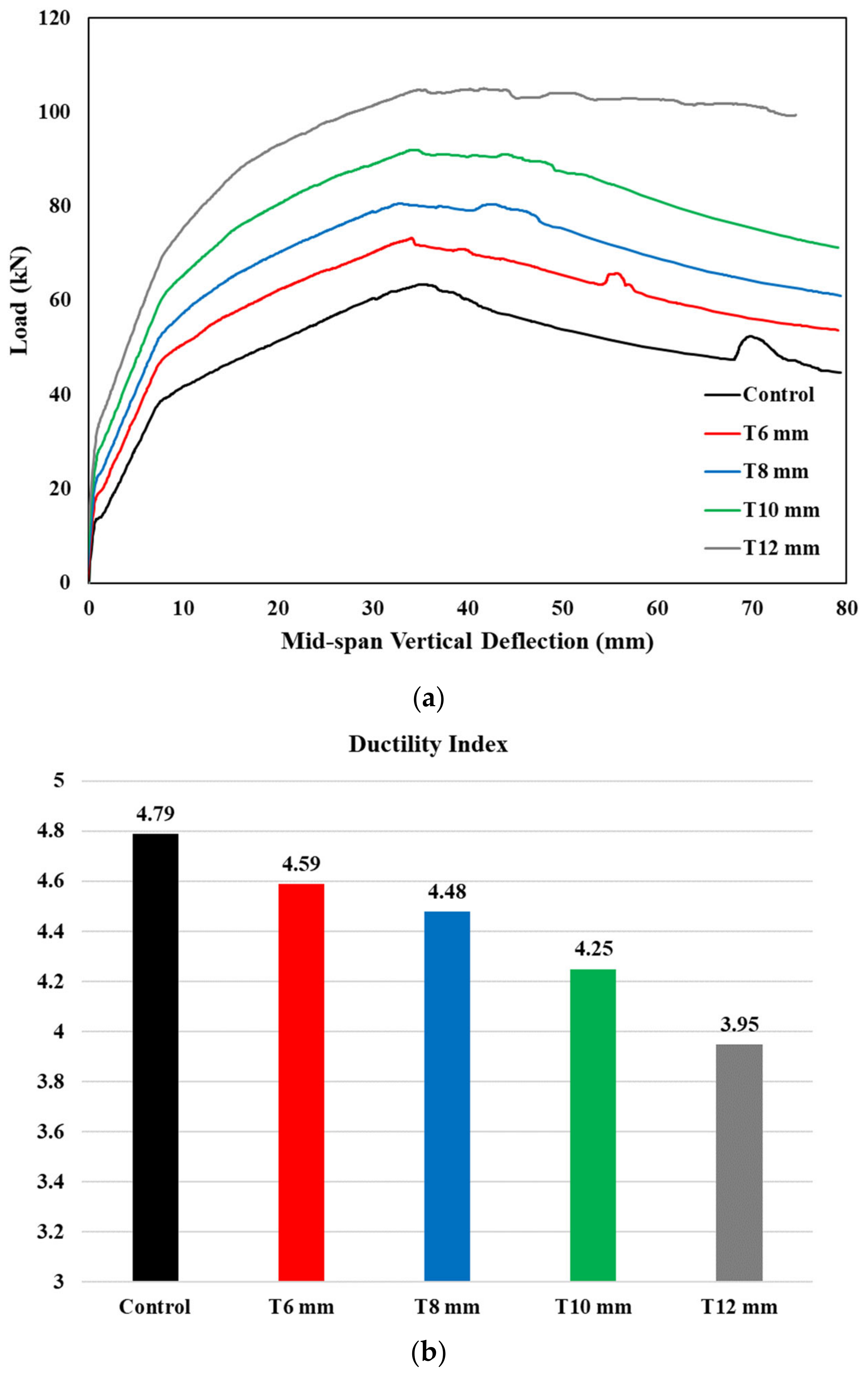
5.2.2. Effect of Changing Fe-SMA Rebar’s Diameter

This section investigates the effect of varying Fe-SMA rebar’s diameter on load-deflection responses of RC beams while maintaining concrete grade and Fe-SMA pre-stressing level constant (40 MPa and 40%, respectively). However, due to the variation in Fe-SMA bar size, the recovery force is varied. Specifically, for Fe-SMA bars of 6, 8, 10, and 12 mm diameter, the applied recovery forces are 8.60, 15.29, 23.86, and 34.35 kN, respectively. Figure 14a compares the control and pre-stressed beams’ load-deflection behavior with four Fe-SMA rebar diameters (6, 8, 10, and 12 mm). All pre-stressed beams achieve higher cracking, yielding, and ultimate loads than the control beam. Furthermore, larger Fe-SMA rebar diameters increase the cracking, yielding, and ultimate loads, as expected. For instance, increasing the diameter of the Fe-SMA from 6 mm to 12 mm improves the cracking, yielding, and ultimate loads by 73, 47, and 43%, respectively. On the other hand, increasing the Fe-SMA diameter results in a slight reduction in the beam’s ductility. Figure 14b presents the specimens’ ductility index, defined as the deflection ratio at the ultimate load to yielding load. The beam pre-stressed with Fe-SMA bars of 12 mm diameter shows the lowest ductility index, indicating the lowest ability to undergo additional deformation after loading to maximum capacity. It can be observed that the ductility index was reduced by 14% with the increase in the diameter of Fe-SMA bars from 6 mm to 12 mm.

5.2.3. Effect of Concrete Grade

This section examines the effects of varying concrete grades (30, 40, 50, and 60 MPa) on the load-deflection response of RC beams while keeping the Fe-SMA pre-stressing level and reinforcement ratio constant (40% and two bars of 8 mm in diameter). It can be observed from Figure 15 that increasing the concrete grade from 30 to 60 MPa produces a 15%, 4%, and 0.75% rise in the cracking, steel yielding, and ultimate loads, respectively. This can be attributed to the fact that at higher loading levels, the compression block becomes smaller, and hence the effect of concrete grade might have a relatively more minor contribution.

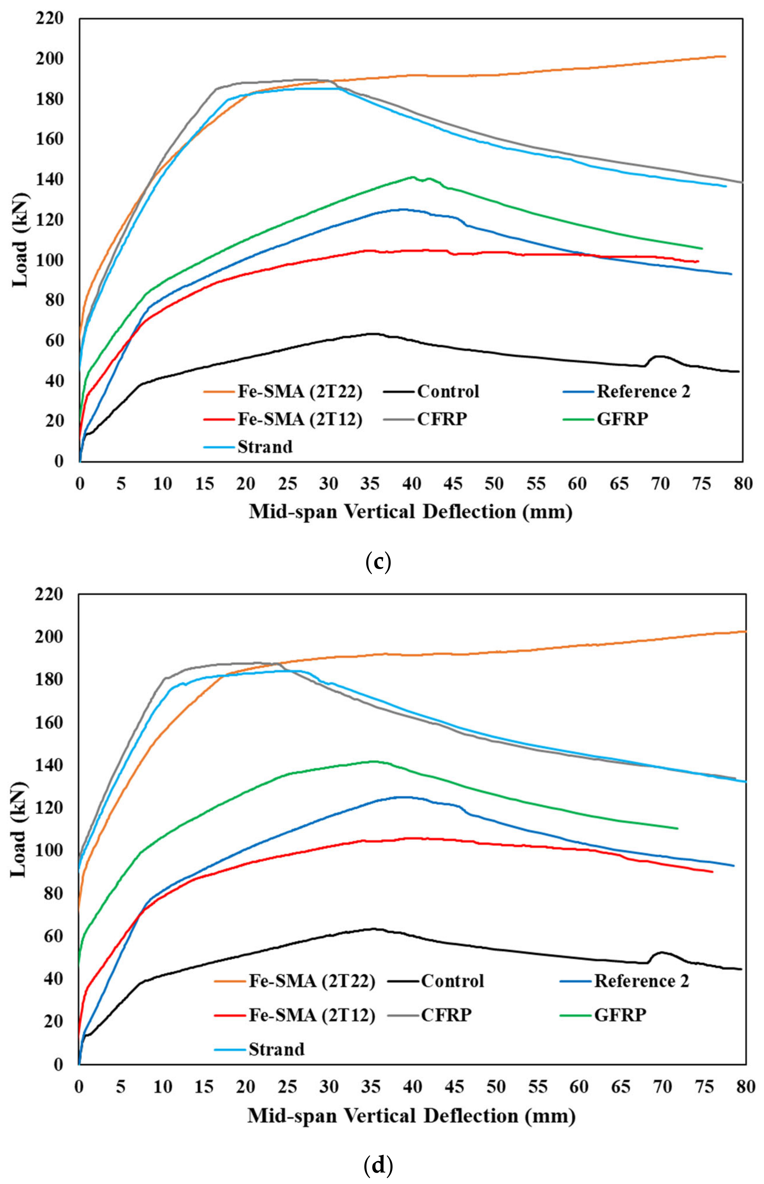
5.2.4. Effect of Varying Strengthening Rebar Types

This section compares RC beams’ load-deflection response with different bars, such as steel strands, CFRP, GFRP, ordinary steel rebars, and Fe-SMA bars. Figure 16 shows that CFRP and steel-strand-reinforced specimens achieve much higher ultimate loads than other specimens; however, they exhibit lower ductility. This is attributed to the higher tensile strength and brittle nature of CFRP and steel strands.
Interestingly, the specimen strengthened by Fe-SMA rebars with a larger diameter (2T22 mm) exhibited superior load-carrying capacity compared to CFRP or steel-strand-reinforced specimens. Furthermore, strengthening with a larger diameter of Fe-SMA bars demonstrates the best service response among all specimens. Additionally, the large diameter Fe-SMA specimen exhibits better post-peak behavior than its counterpart, because more energy is absorbed before failure.
Aside from their ease of use and ease of installation, the cost of larger-diameter Fe-SMA rebars is comparable to the cost of other strengthening techniques having smaller bars’ diameter when considering fabrication and maintenance costs, as reported by Hosseini et al. [19]. This makes the Fe-SMA pre-stressing system a preferred technique to other traditional methods used in the strengthening industry.

6. Conclusions

In this study, the structural performance of RC beams strengthened with Fe-SMA rebars is numerically investigated using FEA software (ABAQUS). The FEM is validated, and a parametric study is carried out to study the effect of different concrete grades, pre-stressing levels, and Fe-SMA bars’ diameter on the load-deflection behavior. Furthermore, the adopted strengthening technique using Fe-SMA bars is compared with other commonly used techniques in the construction field. The following conclusions are made based on the results:
  • Increasing either the pre-stressing level of Fe-SMA bars or the concrete grade enhanced the beam’s response at the serviceability stage but exhibited a minor effect at the ultimate stage. Specifically, increasing the concrete grade from 30 to 60 MPa produces a 15%, 4%, and 0.75% rise in the cracking, steel yielding, and ultimate loads, respectively, for the test specimens.
  • Using a larger diameter of Fe-SMA bars improved the load-carrying capacity but reduced the ductility of test specimens. Specifically, using 12 mm Fe-SMA bars instead of 6 mm increased the beam’s strength by 73% and decreased the ductility by 14%.
  • Strengthening RC beams with 2T22 mm of pre-stressed Fe-SMA bars yielded a better strength and ductility response than other commonly used techniques with 2T12 mm of carbon fiber reinforced polymer (CFRP) bars, glass fiber reinforced polymer (GFRP) bars, and steel strands. Moreover, considering the fabrication cost, the Fe-SMA rebars exhibited a comparable cost to other pre-stressing systems.
  • Further experimental tests are required to further ascertain the reported findings of this numerical investigation. In particular, it is recommended to explore the use of the Fe-SMA bars as the main reinforcement in future research.

Author Contributions

Conceptualization, A.K. and M.E.; methodology, A.K. and M.E.; software, A.K. and M.E.; validation, A.K. and M.E.; formal analysis, A.K. and M.E.; investigation, A.K. and M.E.; resources, A.K., M.E. and W.A.; data curation, A.K. and M.E.; writing—original draft preparation, A.K. and M.E.; writing—review and editing, A.K., M.E., W.A., R.H. and M.A.; visualization, A.K. and M.E.; supervision, W.A., R.H. and M.A.; project administration, W.A., R.H. and M.A.; funding acquisition, W.A., R.H. and M.A. All authors have read and agreed to the published version of the manuscript.

Funding

This research was financially supported by the American University of Sharjah (AUS) through the Ph.D. in Material Science and Engineering (Ph.D.-MSE) Program, and the Open Access Program (OAP).

Data Availability Statement

Not applicable.

Acknowledgments

The authors greatly appreciate the financial support. This paper represents the opinions of the authors and does not mean to represent the position or opinions of the AUS.

Conflicts of Interest

The authors declare no conflict of interest.

References

  1. Aksoylu, C.; Özkılıç, Y.O.; Arslan, M.H. Mechanical Steel Stitches: An Innovative Approach for Strengthening Shear Deficiency in Undamaged Reinforced Concrete Beams. Buildings 2022, 12, 1501. [Google Scholar] [CrossRef]
  2. Gemi, L.; Madenci, E.; Özkılıç, Y.O.; Yazman, S.; Safonov, A. Effect of Fiber Wrapping on Bending Behavior of Reinforced Concrete Filled Pultruded GFRP Composite Hybrid Beams. Polymers 2022, 14, 3740. [Google Scholar] [CrossRef] [PubMed]
  3. Khalil, A.; Etman EA, A.; Essam, M. Strengthening of RC Beams Subjected to Cyclic Load Using Ultra High Performance Strain Hardening Cementitious Composites. ISEC Press 2017, 4, 1–6. [Google Scholar] [CrossRef]
  4. Khalil, A.; Etman EA, A.; Essam, M. Behavior of RC beams strengthened with strain hardening cementitious composites (SHCC) subjected to monotonic and repeated loads. Eng. Struct. 2017, 140, 151–163. [Google Scholar] [CrossRef]
  5. Khalil, A.; Etman, E.A.A.; Atta, A.; Essam, M. Nonlinear behavior of RC beams strengthened with strain hardening cementitious composites subjected to monotonic and cyclic loads. Alex. Eng. J. 2016, 55, 1483–1496. [Google Scholar] [CrossRef]
  6. Peng, G.; Niu, D.; Hu, X.; Zhong, S.; Huang, D. Experimental and theoretical study on the flexural behavior of RC beams strengthened with cementitious grout. Eng. Struct. 2022, 267, 114713. [Google Scholar] [CrossRef]
  7. Hawileh, R.A. Nonlinear finite element modeling of RC beams strengthened with NSM FRP rods. Constr. Build. Mater. 2012, 27, 461–471. [Google Scholar] [CrossRef]
  8. Hawileh, R.A.; Naser, M.; Zaidan, W.; Rasheed, H.A. Modeling of insulated CFRP-strengthened reinforced concrete T-beam exposed to fire. Eng. Struct. 2019, 31, 3072–3079. [Google Scholar] [CrossRef]
  9. Hawileh, R.A.; Rasheed, H.A.; Abdalla, J.A.; Al-Tamimi, A.K. Behavior of reinforced concrete beams strengthened with externally bonded hybrid fiber reinforced polymer systems. Mater. Des. 2014, 53, 972–982. [Google Scholar] [CrossRef] [Green Version]
  10. Sun, Y.; Wu, T.; Liu, X. Design of concrete beams reinforced and unbonded pre-stressed with FRP bars based on serviceability requirements. Compos. Struct. 2022, 300, 116133. [Google Scholar] [CrossRef]
  11. Su, M.; Gong, S.; Liu, Y.; Peng, H. Flexural behavior of RC beams strengthened with fully or partially pre-stressed near-surface mounted FRP strips: An experimental investigation. Eng. Struct. 2022, 262, 114345. [Google Scholar] [CrossRef]
  12. Hakan, A.M.; Yazman, Ş.; Hamad, A.A.; Aksoylu, C.; Özkılıç, Y.O.; Gemi, L. Shear strengthening of reinforced concrete T-beams with anchored and non-anchored CFRP fabrics. Structures 2022, 39, 527–542. [Google Scholar]
  13. Gemi, L.; Alsdudi, M.; Aksoylu, C.; Yazman, Ş.; Özkılıç, Y.O.; Arslan, M.H. Optimum amount of CFRP for strengthening shear deficient reinforced concrete beams. Steel Compos. Struct. 2022. [Google Scholar] [CrossRef]
  14. Nie, X.F.; Zhang, S.S.; Teng, J.G. Strengths of RC beams with a fibre-reinforced polymer (FRP)-strengthened web opening. Compos. Struct. 2021, 258, 113380. [Google Scholar] [CrossRef]
  15. Najaf, E.; Orouji, M.; Ghouchani, K. Finite element analysis of the effect of type, Number, and Installation Angle of FRP Sheets on improving the Flexural Strength of Concrete Beams. Case Stud. Constr. Mater. 2022, 17, e01670. [Google Scholar] [CrossRef]
  16. Alhamaydeh, M.; Barakat, S.; Abed, F. Multiple Regression Modeling of Natural Rubber Seismic-Isolation Systems with Supplemental Viscous Damping for Near-Field Ground Motion. J. Civ. Eng. Manag. 2013, 19, 665–682. [Google Scholar] [CrossRef]
  17. Alhamaydeh, M.; Aly, N.; Galal, K. Seismic Response and Life-Cycle Cost of Reinforced Concrete Special Structural Wall Buildings in Dubai, UAE. Struct. Concr. 2018, 19, 771–782. [Google Scholar] [CrossRef]
  18. AlHamaydeh, M.; Orabi, M. Punching Shear Behavior of Synthetic Fiber-Reinforced Self-Consolidating Concrete Flat Slabs with GFRP Bars. J. Compos. Constr. ASCE 2021, 25, 04021029. [Google Scholar] [CrossRef]
  19. Hosseini, A.; Michels, J.; Izadi, M.; Ghafoori, E. A comparative study between Fe-SMA and CFRP reinforcements for pre-stressed strengthening of metallic structures. Constr. Build Mater. 2019, 26, 976–992. [Google Scholar] [CrossRef]
  20. Youssef, M.A.; Alam, M.S.; Nehdi, M. Experimental investigation on the seismic behavior of beam-column joints reinforced with superelastic shape memory alloys. J. Earthq. Eng. 2008, 12, 1205–1222. [Google Scholar] [CrossRef]
  21. Ghafoori, E.; Hosseini, A.; Michels, J.; Izadi, M.R.; Pellissier, E. Iron-Based Shape Memory Alloy (Fe-SMA) vs. CFRP for Pre-stressed Strengthening of Civil Metallic Structures. In Proceedings of the International Conference on Fibre-Reinforced Polymer (FRP) Composites in Civil Engineering, Istanbul, Turkey, 8–10 December 2021; pp. 2139–2153. [Google Scholar]
  22. Karbhari, V.M.; Chin, J.W.; Hunston, D.; Benmokrane, B. Durability gap analysis for fiber-reinforced polymer composites in civil infrastructure. J. Compos. Constr. 2003, 7, 238–247. [Google Scholar] [CrossRef]
  23. Lee, W.J.; Partovi-Nia, R.; Suter, T.; Leinenbach, C. Electrochemical characterization and corrosion behavior of an Fe-Mn-Si shape memory alloy in simulated concrete pore solutions. Mater. Corros. 2016, 67, 839–846. [Google Scholar] [CrossRef]
  24. Sidharth, R.; Abuzaid, W.; Vollmer, M.; Niendorf, T.; Sehitoglu, H. Fatigue crack initiation in the iron-based shape memory alloy FeMnAlNiTi. Shape Mem. Superelast. 2020, 6, 323–331. [Google Scholar] [CrossRef]
  25. Abouali, S.; Shahverdi, M.; Ghassemieh, M.; Motavalli, M. Nonlinear simulation of reinforced concrete beams retrofitted by near-surface mounted iron-based shape memory alloys. Eng. Struct. 2019, 187, 133–148. [Google Scholar] [CrossRef]
  26. Yeon, Y.-M.; Lee, W.; Hong, K.-N. Finite Element Analysis of Reinforced Concrete Beams Prestressed by Fe-Based Shape Memory Alloy Bars. Appl. Sci. 2022, 12, 3255. [Google Scholar] [CrossRef]
  27. Elkafrawy, M.E.; Khalil, A.M.; Abuzaid, W.; Hawileh, R.A.; AlHamaydeh, M. Nonlinear Finite Element Analysis (NLFEA) of Pre-stressed RC Beams Reinforced with Iron-Based Shape Memory Alloy (Fe-SMA). In Proceedings of the 2022 Advances in Science and Engineering Technology International Conferences (ASET), Dubai, United Arab Emirates, 21–24 February 2022; pp. 1–7. [Google Scholar]
  28. Smith, M. ABAQUS/Standard User’s Manual, Version 6.9; Dassault Systèmes Simulia Corp: Johnston, RI, USA, 2009. [Google Scholar]
  29. ASTM D790-07; Standard Test Methods for Flexural Properties of Unreinforced and Reinforced Plastics and Electrical Insulating Materials. ASTM International: West Conshohocken, PA, USA, 2007.
  30. Hafezolghorani, M.; Hejazi, F.; Vaghei, R.; Jaafar, M.S.b.; Karimzade, K. Simplified damage plasticity model for concrete. Struct. Eng. Int. 2017, 27, 68–78. [Google Scholar] [CrossRef]
  31. Shahverdi, M.; Czaderski, C.; Annen, P.; Motavalli, M. Strengthening of RC beams by iron-based shape memory alloy bars embedded in a shotcrete layer. Eng. Struct. 2016, 117, 263–273. [Google Scholar] [CrossRef]
  32. Ölander, A. An electrochemical investigation of solid cadmium-gold alloys. J. Am. Chem. Soc. 1932, 54, 3819–3833. [Google Scholar] [CrossRef]
  33. Furuya, Y. Design and material evaluation of shape memory composites. J. Intell. Mater. Syst. Struct. 1996, 7, 321–330. [Google Scholar] [CrossRef]
  34. Hartl, D.J.; Lagoudas, D.C. Aerospace applications of shape memory alloys. Proc. Inst. Mech. Eng. G J. Aerosp. Eng. 2007, 221, 535–552. [Google Scholar] [CrossRef] [Green Version]
  35. Bil, C.; Massey, K.; Abdullah, E.J. Wing morphing control with shape memory alloy actuators. J. Intell. Mater. Syst. Struct. 2013, 24, 879–898. [Google Scholar] [CrossRef]
  36. Sreekumar, M.; Nagarajan, T.; Singaperumal, M.; Zoppi, M.; Molfino, R. Critical review of current trends in shape memory alloy actuators for intelligent robots. Ind. Robot. Int. J. 2007, 34, 285–294. [Google Scholar] [CrossRef]
  37. Kheirikhah, M.M.; Rabiee, S.; Edalat, M.E. A Review of Shape Memory Alloy Actuators in Robotics BT—RoboCup 2010: Robot Soccer World Cup XIV; Ruiz-del-Solar, J., Chown, E., Plöger, P.G., Eds.; Springer: Berlin/Heidelberg, Germany, 2011; pp. 206–217. [Google Scholar]
  38. Mantovani, D. Shape memory alloys: Properties and biomedical applications. Jom 2000, 52, 36–44. [Google Scholar]
  39. Janke, L.; Czaderski, C.; Motavalli, M.; Ruth, J. Applications of shape memory alloys in civil engineering structures—Overview, limits and new ideas. Mater. Struct. 2005, 38, 578–592. [Google Scholar]
  40. Czaderski, C.; Shahverdi, M.; Brönnimann, R.; Leinenbach, C.; Motavalli, M. Feasibility of iron-based shape memory alloy strips for pre-stressed strengthening of concrete structures. Constr. Build. Mater. 2014, 56, 94–105. [Google Scholar] [CrossRef]
  41. Abuzaid, W.; Wu, Y.; Sidharth, R.; Brenne, F.; Alkan, S.; Vollmer, M.; Sehitoglu, H. FeMnNiAl iron-based shape memory alloy: Promises and challenges. Shape Mem. Superelasticity 2019, 5, 263–277. [Google Scholar] [CrossRef]
  42. Schranz, B.; Czaderski, C.; Vogel, T.; Shahverdi, M. Bond investigations of pre-stressed, near-surface-mounted, ribbed memory-steel bars with full bond length. Mater. Des. 2020, 196, 109145. [Google Scholar] [CrossRef]
  43. Cladera, A.; Weber, B.; Leinenbach, C.; Czaderski, C.; Shahverdi, M.; Motavalli, M. Iron-based shape memory alloys for civil engineering structures: An overview. Constr. Build. Mater. 2014, 63, 281–293. [Google Scholar] [CrossRef]
  44. Ghafoori, E.; Neuenschwander, M.; Shahverdi, M.; Czaderski, C.; Fontana, M. Elevated temperature behavior of an iron-based shape memory alloy used for pre-stressed strengthening of civil structures. Constr. Build. Mater. 2019, 211, 437–452. [Google Scholar] [CrossRef]
  45. Michels, J.; Shahverdi, M.; Czaderski, C.; Schranz, B.; Motavalli, M. Iron based shape memory alloy strips, part 2: Flexural strengthening of RC beams. In Proceedings of the Fourth International Conference on Smart Monitoring, Assessment and Rehabilitation of Civil Structures (SMAR 2017), Zurich, Switzerland, 15 September 2017. [Google Scholar]
  46. Shahverdi, M.; Michels, J.; Czaderski, C.; Motavalli, M. Iron-based shape memory alloy strips for strengthening RC members: Material behavior and characterization. Constr. Build. Mater. 2018, 173, 586–599. [Google Scholar] [CrossRef]
  47. Yamauchi, K. Shape Memory and Superelastic Alloys: Technologies and Applications; Woodhead Publishing: Sawston, UK, 2011. [Google Scholar]
  48. Lee, W.J.; Weber, B.; Leinenbach, C. Recovery stress formation in a restrained Fe–Mn–Si-based shape memory alloy used for pre-stressing or mechanical joining. Constr. Build. Mater. 2015, 95, 600–610. [Google Scholar] [CrossRef]
  49. Joo, J.; Kang, M.; Shin, D.; Seo, E.; Kim, D.; Yeon, Y.; Hong, K.; Lee, W.; Lee, J. Corrosion Resistance of Shape Recoverable Fe-17Mn-5Si-5Cr Alloy in Concrete Structures. Materials 2020, 13, 5531. [Google Scholar] [CrossRef]
  50. Hong, K.N.; Yeon, Y.M.; Shim, W.B.; Kim, D.H. Recovery Behavior of Fe-Based Shape Memory Alloys under Different Restraints. Appl. Sci. 2020, 10, 3441. [Google Scholar] [CrossRef]
  51. Strieder, E.; Aigner, C.; Petautschnig, G.; Horn, S.; Marcon, M.; Schwenn, M.; Zeman, O.; Castillo, P.; Wan-Wendner, R.; Bergmeister, K. Strengthening of Reinforced Concrete Beams with Externally Mounted Sequentially Activated Iron-Based Shape Memory Alloys. Materials 2019, 12, 345. [Google Scholar] [CrossRef] [Green Version]
  52. El-Hacha, R. Self-Prestressing Using Fe-SMA for Flexural Strengthening of Reinforced Concrete Beams. Artic. Aci Struct. J. 2017, 114, 523–532. [Google Scholar] [CrossRef]
  53. Zuaiter, M.; El-Hassan, H.; El-Ariss, B.; El-Maaddawy, T. Early-Age Properties of Slag-Fly Ash Blended Geopolymer Concrete Reinforced with Glass Fibers–A Preliminary Study. In Proceedings of the 7th World Congress on Civil, Structural, and Environmental Engineering (CSEE’22), Lisbon, Portugal, 10–12 April 2022; p. 7. [Google Scholar]
  54. Zuaiter, M.; El-Hassan, H.; El-Maaddawy, T.; El-Ariss, B. Properties of Slag-Fly Ash Blended Geopolymer Concrete Reinforced with Hybrid Glass Fibers. Buildings 2022, 12, 1114. [Google Scholar] [CrossRef]
  55. Alkhraisha, H.; Mhanna, H.; Tello, N.; Abed, F. Serviceability and Flexural Behavior of Concrete Beams Reinforced with Basalt Fiber-Reinforced Polymer (BFRP) Bars Exposed to Harsh Conditions. Polymers 2020, 12, 2110. [Google Scholar] [CrossRef]
  56. Hong, K.; Lee, S.; Yeon, Y.; Jung, K. Flexural response of reinforced concrete beams strengthened with near-surface-mounted Fe-based shape-memory alloy strips. Int. J. Concr. Struct. Mater. 2018, 12, 1–13. [Google Scholar] [CrossRef]
  57. Yeon, Y.-M.; Hong, K.-N.; Lee, S.; Ji, S.-W. Numerical study of RC beams strengthened with Fe-based shape memory alloy strips using the NSM method. Appl. Sci. 2021, 11, 6809. [Google Scholar] [CrossRef]
  58. Ruiz-Pinilla, J.G.; Montoya-Coronado, L.A.; Ribas, C.; Cladera, A. Finite element modeling of RC beams externally strengthened with iron-based shape memory alloy (Fe-SMA) strips, including analytical stress-strain curves for Fe-SMA. Eng. Struct. 2020, 223, 111152. [Google Scholar] [CrossRef]
  59. Dolatabadi, N.; Shahverdi, M.; Ghassemieh, M.; Motavalli, M. RC Structures strengthened by an iron-based shape memory alloy embedded in a shotcrete layer—Nonlinear finite element modeling. Materials 2020, 13, 5504. [Google Scholar] [CrossRef]
  60. Lundqvist, J.; Nordin, H.; Täljsten, B.; Olofsson, T. Numerical Analysis of Concrete Beams Strengthened with CFRP-A Study of Anchorage Lengths. In Proceedings of the International Symposium on Bond Behaviour of FRP in Structures (BBFS 2005), Hong Kong, China, 7–9 December 2005. [Google Scholar]
  61. Elbahy, Y.I.; Youssef, M.A. Flexural behaviour of superelastic shape memory alloy reinforced concrete beams during loading and unloading stages. Eng. Struct. 2019, 181, 246–259. [Google Scholar] [CrossRef]
  62. Hong, K.-N.; Yeon, Y.-M.; Ji, S.-W.; Lee, S. Flexural Behavior of RC Beams Using Fe-Based Shape Memory Alloy Rebars as Tensile Reinforcement. Buildings 2022, 12, 190. [Google Scholar] [CrossRef]
  63. Qian, H.; Zhang, Q.; Zhang, X.; Deng, E.; Gao, J. Experimental Investigation on Bending Behavior of Existing RC Beam Retrofitted with SMA-ECC Composites Materials. Materials 2022, 15, 12. [Google Scholar] [CrossRef]
  64. Christoforo, A.L.; Carvalho, R.C. Calibration of Concrete Damaged Plasticity Model parameters for shear walls. Matéria 2021, 26. [Google Scholar] [CrossRef]
  65. Hussain, I.; Yaqub, M.; Ehsan, A.; Rehman, S.U. Effect of viscosity parameter on numerical simulation of fire damaged concrete columns. Civ. Eng. J. 2019, 5, 1841–1849. [Google Scholar] [CrossRef]
  66. Śledziewski, K. Selection of appropriate concrete model in numerical calculation. ITM Web Conf. 2017, 15, 07012. [Google Scholar] [CrossRef] [Green Version]
  67. Madkour, H.; Maher, M.; Ali, O. Finite element analysis for interior slab-column connections reinforced with GFRP bars using damage plasticity model. J. Build. Eng. 2022, 48, 104013. [Google Scholar] [CrossRef]
  68. Akinpelu, M.; Adedeji, A.A. Structural response of reinforced self-compacting concrete deep beam using finite element method. J. Soft Comput. Civ. Eng. 2018, 2, 36–61. [Google Scholar]
  69. Demir, A.; Ozturk, H.; Dok, G. 3D numerical modeling of RC deep beam behavior by nonlinear finite element analysis. Disaster Sci. Eng. 2016, 2, 13–18. [Google Scholar]
  70. Wang, J.; Jivkov, A.P.; Li, Q.M.; Engelberg, D.L. Experimental and numerical investigation of mortar and ITZ parameters in meso-scale models of concrete. Theor. Appl. Fract. Mech. 2020, 109, 102722. [Google Scholar] [CrossRef]
  71. Senthil, K.; Kubba, Z.; Sharma, R.; Thakur, A. Experimental and Numerical Investigation on Reinforced Concrete Slab under Low Velocity Impact Loading. In IOP Conference Series: Materials Science and Engineering, Proceedings of the 1st International Conference on Engineering Science and Technology (ICEST 2020), Samawah, Iraq, 23–24 December 2020; IOP Publishing: Bristol, UK, 2021; Volume 1090, p. 012090. [Google Scholar]
  72. Michał, S.; Andrzej, W. Calibration of the CDP model parameters in Abaqus. In Proceedings of the 2015 Wourld Congress on Advances in Structural Engineering and Mechanics (ASEM15), Incheon, Republic of Korea, 25–29 August 2015. [Google Scholar]
  73. Szczecina, M.; Winnicki, A. Relaxation time in CDP model used for analyses of RC structures. Procedia Eng. 2017, 193, 369–376. [Google Scholar] [CrossRef]
  74. Simulia. ABAQUS/CAE User’s Manual; Simulia: Johnston, RI, USA, 1991. [Google Scholar]
  75. ABAQUS Version 6.6 Documentation. Available online: https://classes.engineeRing.wustl.edu/2009/spring/mase5513/abaqus/docs/v6.6/index.html (accessed on 4 December 2021).
  76. Hognestad, E. Study of Combined Bending and Axial Load in Reinforced Concrete Members; A Report of an Investigation; Bulletin Series No. 399; University of Illinois: Champaign, IL, USA, 1951; Volume 49. [Google Scholar]
  77. Kent, D.C.; Park, R. Flexural members with confined concrete. J. Struct. Div. 1971, 97, 1969–1990. [Google Scholar] [CrossRef]
  78. Hsu, L.S.; Hsu, C.T. Complete stress—Strain behaviour of high-strength concrete under compression. Mag. Concr. Res. 1994, 46, 301–312. [Google Scholar] [CrossRef]
  79. Dassault Systèmes. ABAQUS 6.11, Abaqus/CAE User’s Manual; Dassault Systèmes: Vélizy-Villacoublay, France, 2011. [Google Scholar]
  80. Van Mier JG, M.; Shah, S.P.; Arnaud, M.; Balayssac, J.P.; Bascoul, A.; Choi, S.; Zissopoulos, D. Strain softening of concrete in uniaxial compression. Mater. Struct. 1997, 30, 195–209. [Google Scholar] [CrossRef]
  81. Comite Euro-International Du Beton. CEB-FIP Model Code 1990: Design Code; Thomas Telford Publishing: London, UK, 1993. [Google Scholar]
  82. Raad, J.; Parvin, A. Iron-based shape memory alloy and fiber reinforced polymers rods for pre-stressed NSM strengthening of RC beams. Eng. Struct. 2020, 207, 110274. [Google Scholar] [CrossRef]
  83. Afefy, H.M.; Abdel-Aziz, M.A.; Kassem, N.M.; Mahmoud, M.H. Improving flexural performance of post-tensioned pre-cast pre-stressed RC segmental T-beams. In Structures; Elsevier: Amsterdam, The Netherlands, 2020; Volume 24, pp. 304–316. [Google Scholar]
Figure 1. Beam details in (a) elevation and cross-section of (b) beam 10 (strengthened by 2T8 mm Fe-SMA bars) and (c) beam 11 (strengthened by 4T8 mm Fe-SMA bars) [31].
Buildings 12 02228 g001
Figure 2. Concrete response to uniaxial compressive loading [30].
Buildings 12 02228 g002
Figure 3. Normalized stress–strain curve according to Hsu et al. [78].
Buildings 12 02228 g003
Figure 4. Concrete response to uniaxial tensile loading [30].
Buildings 12 02228 g004
Figure 5. Tensile stress versus crack opening (tension stiffening).
Buildings 12 02228 g005
Figure 6. Damage behavior of concrete in (a) compression and (b) tension [30].
Buildings 12 02228 g006
Figure 7. Stress–strain relationship of (a) CFRP, steel rebar, strand, and GFRP in ABAQUS, (b) Fe-SMA from experiment [31], and (c) Fe-SMA curve defined in ABAQUS.
Buildings 12 02228 g007
Figure 8. Mesh configuration for (a) concrete and (b) steel reinforcement.
Buildings 12 02228 g008
Figure 9. Effect of pre-stressing the Fe-SMA.
Buildings 12 02228 g009
Figure 10. Details of specimens of the parametric study. (a) Four-point loading test setup, cross-sectional details of (b) control beam, (c) Pre-stressed Beam, (d) Reference Beam 1, (e) Reference Beam 2.
Buildings 12 02228 g010aBuildings 12 02228 g010b
Figure 11. Load-deflection response for beams 10 and 11 [31]: (a) beam 10, (b) beam 11.
Buildings 12 02228 g011
Figure 12. FE model and experimental crack patterns: (a) beam 10, (b) beam 11.
Buildings 12 02228 g012
Figure 13. Load-deflection response for different pre-stressing levels: (a) full curve, (b) zoom of (a).
Buildings 12 02228 g013aBuildings 12 02228 g013b
Figure 14. Effect of varying Fe-SMA bar diameter on (a) load-deflection behavior and (b) ductility index.
Buildings 12 02228 g014
Figure 15. (a) Effect of varying the concrete compressive grade on the load-deflection behavior; (b) zoom of (a).
Buildings 12 02228 g015
Figure 16. Effect of varying strengthening material types on the load-deflection behavior of beams subjected to different pre-stressing levels: (a) non-pre-stressed, (b) 20% pre-stressing level, (c) 40% pre-stressing level, (d) 60% pre-stressing level.
Buildings 12 02228 g016aBuildings 12 02228 g016b
Table 1. Plasticity parameters utilized in ABAQUS simulations for CDP.
Dilation AngleEccentricity (e)fb0/fc0KViscosity Parameter
550.11.160.670.0001
Publisher’s Note: MDPI stays neutral with regard to jurisdictional claims in published maps and institutional affiliations.

