Article

Study on the Constitutive Model of Concrete Confined by Multi-Spiral Composite Stirrups

School of Civil Engineering, Chang’an University, Xi’an 710061, China
*
Author to whom correspondence should be addressed.
Buildings 2022, 12(12), 2179; https://doi.org/10.3390/buildings12122179
Submission received: 14 November 2022 / Revised: 3 December 2022 / Accepted: 6 December 2022 / Published: 9 December 2022
(This article belongs to the Special Issue Improvement Technology on Building Seismic Toughness)

Abstract

:
Through axial compression tests, the influence of three stirrup indexes (space, form, and strength) on the confining performance of multi-spiral composite stirrups in square reinforced concrete (RC) columns were analyzed, and the square RC columns with traditional well-shaped composite stirrups were used as the reference group. The results show that the multi-spiral composite stirrups had a positive contribution to the important indexes (bearing capacity and ductility) of the square RC columns due to its multiple restraint mechanism on core concrete. In terms of constraint effect, the five-spiral composite stirrup is the best, followed by the four-spiral composite stirrup, and the last is the traditional well-shaped composite stirrup. The section of the concrete square column is divided into highly constrained, partially constrained and unconstrained regions and the constraint mechanism of multi-spiral composite stirrups is discussed. The formulas for calculating the peak stress, peak strain, and ultimate compressive strain of the constrained column are presented, and the relative error between the theoretical values and the tested values is small. The constitutive model of concrete constrained by multi-spiral composite stirrups is established and compared with other constitutive models. The results show that the proposed model fits well with the experimental curves.

1. Introduction

China is one of the countries most affected by earthquake disasters. The earthquake damage shows that the reinforced concrete (RC) columns in the building have been damaged to different degrees, especially the columns located at the bottom of the whole structure are often the most seriously damaged at the column end [1,2]. The failure of the column end may cause the rapid degradation of the bearing capacity or even the continuous collapse of the column. The lateral constraint of the RC column can not only help it support more vertical load, but also increase the deformation capacity of the column. General constraint methods can be divided into active and passive constraints. In related research, passive restraint methods such as square hoops, spiral stirrups [3], steel pipes [4], fiber materials [5], or their combinations [6,7,8,9,10,11] are used to provide effective lateral restraint for concrete. Studies have proved that using stirrup to constrain concrete can enhance the mechanical properties of columns, thereby preventing or delaying serious damage to columns [12]. Among them, the traditional spiral stirrup is widely used in a cylinder because of its good constraint effect, and its confining effect on a cylinder is generally better than that on rectangular stirrups columns (including square columns).
Scholars abroad and at home have conducted a series of investigations on the performance of concrete confined with stirrups. For the purpose of obtaining the exact strength of constrained concrete, Skeikh and Uzumeri [13] fully considered the influence of stirrup spacing and lengthways reinforcement arrangement, and analyzed the effectively constrained area in the core concrete area. Based on that, they obtained the stress–strain expression of constrained concrete. Mander et al. [14,15] provided a stress–strain model for constrained concrete considering the effects of strain rate and cyclic loading. The model fully considered the arch function between rectangular stirrups and lengthways reinforcement and defined the concept of effectively constrained area based on this model. It is suitable for various restraint forms such as traditional rectangular hoops, spiral stirrups, etc. Cusson et al. [16,17] believed that the axial compressive strength of restrained concrete columns would arrive at its peak point before the stirrup stress, and proposed an innovative method to calculate the actual stirrup stress under the peak stress of the constrained concrete. Saatcioglu and Razvi [18] established a constitutive model curve composed of ascending parabola segments and descending straight segments based on the concept of equivalent constrained stress. Later, Bing et al. [19] combined the model of Mander and Saatcioglu and proposed a fitting equation for the ultimate longitudinal strain of high-strength concrete. This formula is suitable for the fracture of the first rectangular hoop or spiral stirrup. Through the axial compression test of high-strength multi-spiral stirrup columns, Rong et al. [20] proposed a new energy absorption method and established a relationship between energy absorption and lateral confinement in concrete columns. Then, the passive strain model, the boundary point model, and the constraint coefficient model of the passive restrained concrete are proposed. Li et al. [21,22] proposed an analytical method for the axial performance of high-strength multi-spiral reinforced concrete columns based on strain compatibility and presented an iterative method for calculating the actual stress of spiral stirrup when concrete is located at peak stress. Through the axial compression experiment of restrained high-strength concrete, Shi and Yang et al. [23,24] believed that the real stress of a high-strength stirrup should be used when considering the restrained stress of a high-strength stirrup, so as to ensure accuracy in judging the effect of strength improvement on concrete columns. Ouyang et al. [25] unified three strength levels of concrete into their calculation formula for a compressive stress–strain curve. According to the experimental results of 42 concrete cylinders confined by a spiral stirrup, Zheng et al. [26] investigated the relationship between stirrup tensile strain under peak compressive stress and three stirrup factors (volume stirrup, yield strength, and spacing). In the end, the constitutive model for this type of column was derived. In order to study the mechanical properties and size-effect behavior of a large RC column confined by stirrups under axial compression loads, Jin et al. [27] carried out corresponding tests and established a constitutive model of an RC column confined by stirrups with size-effect. Li et al. [28] tested a total of six RC columns confined by composite spiral stirrups under eccentric loading with different stirrup spacing and force eccentricities. The experimental analyses explained that the dual confinement of the concrete consisting of core confinement by spiral stirrups and surrounding confinement by rectangular hoops had significant effects on failure modes. Finally, a formula for calculating the eccentric loading capacity of composite spiral stirrups confined concrete columns was proposed.
In practical engineering, a rectangular (or square) column is more applicable than a circular column. In order to solve the problem that spiral stirrups do not adapt to rectangular (or square) columns, Yin [29,30] developed a series of new restraint types of rectangular RC columns and proved that spiral stirrups can also show good restraint effects in those columns through a number of experimental researches. Subsequently, in terms of the axial compression test of large-size SRC (steel reinforced concrete) columns and RC (reinforced concrete) columns equipped with five-spiral stirrups, Yin et al. [31] believed that the new five-spiral SRC column has excellent strength and ductility under the premise of the same total longitudinal steel. In addition, the five-spiral stirrups can be processed automatically, which can shorten the construction period in engineering practice and bring economic benefits. Then, Yin et al. [32,33] carried out a large number of axial compression and transverse cyclic load tests on concrete column specimens equipped with four different stirrup forms (traditional well-shape, four-spiral, five-spiral, and spiral with cross cable ties). The test results show that each spiral stirrup contributes to the overall pressure, which makes the degradation of strength more slowly after the peak stress point. In addition, the axial pressure of each constraint region in the section depends on the geometric area of the spiral stirrup. Hung et al. [34] proposed a pier system with cross multi-spiral composite stirrups. It is proved that this pier system not only contributes to the enhancement of strength and ductility but also has advantages in cost-effectiveness and constructability. The experiment conducted by Chen et al. [35] indicated that the strength and ductility of columns are increased by 33% and 145% under axial compression, and by 7.14% and 21.4% under eccentric compression, respectively. When the overlap area of the stirrup increases to 10%, the above two analysis indexes increase by 2.56% and 11.25%, respectively. Weng et al. [36] used five-spiral stirrups in concrete rectangular columns and proved the effectiveness of five-spiral stirrups in such applications. Shih et al. [37] came up with a new type of interlocking spiral stirrup for a rectangular column, in which a circular spiral stirrup is interlocked with a star-shaped spiral stirrup to improve its restraint effect. Wu et al. [38] proposed the section constraint form of six-interlocking spiral transverse RC columns and proved through tests that the ductility of such specimens was significantly higher than the requirements of the design specifications. Tang et al. [39] used the finite element method (FEM) to study the varying law of stress distribution in sections of concrete columns with stirrup constraints. The analysis results show that the stress and area of the core section of the column increase obviously. The small spiral stirrup located at four corners can compensate for the stress reduction because of the existence of plain concrete. Finally, a more accurate calculation formula for loading capacity for this type of column is given. Using the simplified elastic finite element method and experiment results, Wang et al. [40] found that the constrained area is closely related to the radius ratio of different spiral stirrups and positively related to the bearing capacity of the column. At present, the application of circular spiral stirrup in rectangular RC columns (or squares) needs further study.
In summary, based on the axial compression test of square RC columns confined by multi-spiral composite stirrups, the constraint mechanism of this type of stirrup and its corresponding constitutive model is studied in this paper.

2. Research Significance

A traditional spiral stirrup is only suitable for a circular column, but the research on multi-spiral composite stirrups breaks through this limitation and applies spiral stirrup to the square column. At present, the application of multi-spiral composite stirrups is not common in many countries, and there is a lack of applied research for corresponding standards. The design of carrying capacity for this type of column is not reflected in the national standards. Therefore, based on the corresponding experimental and theoretical analysis, this paper discusses the curve of stress–strain relationship and the calculation formula of related parameters, so as to provide a reference for the study of mechanical properties of this type of column and its engineering application.

3. Experiment

3.1. Test Program

In this test [41], 8 RC column specimens were designed and fabricated, including 7 specimens with multi-spiral composite stirrup and 1 specimen with traditional well-type stirrup. The size of the square column was 260 × 260 × 750 (mm), and the thickness of the concrete protective layer was 10mm. The design of the specimen mainly considered three variables: stirrup strength, stirrup spacing, and stirrup form. The specific size, stirrup form, and corresponding geometric model of the specimen are shown in Figure 1, and the design parameters are shown in Table 1. In Table 1, stirrup types include A (quadruple spiral composite stirrup), B (five-spiral composite stirrup), and C (traditional well composite stirrup). The ratio of the volume hoop ρ v refers to the ratio of the stirrup volume to the corresponding concrete volume within a stirrup spacing. f c u is the cube compressive strength of concrete measured by using a 150 mm × 150 mm × 150 mm cube as the sample of standard. f c is the axial compressive strength of concrete measured by using 150 mm × 150 mm × 300 mm prisms as the sample of standard. Longitudinal compression reinforcement is made of HPB235 steel with a diameter of 8 mm. The strength grades and mechanical properties of the three stirrups are shown in Table 2.
The production process of the specimens includes: binding the steel cage; sticking the strain gauge on the steel bar; building formwork on the outside of the steel cage; pouring concrete into the cage along the long side of the formwork; vibrating concrete until it compacts; conserving for 28 days under natural conditions; removing the concrete formwork; attaching strain gauge to the concrete surface. Figure 2 shows the main process of specimen production.
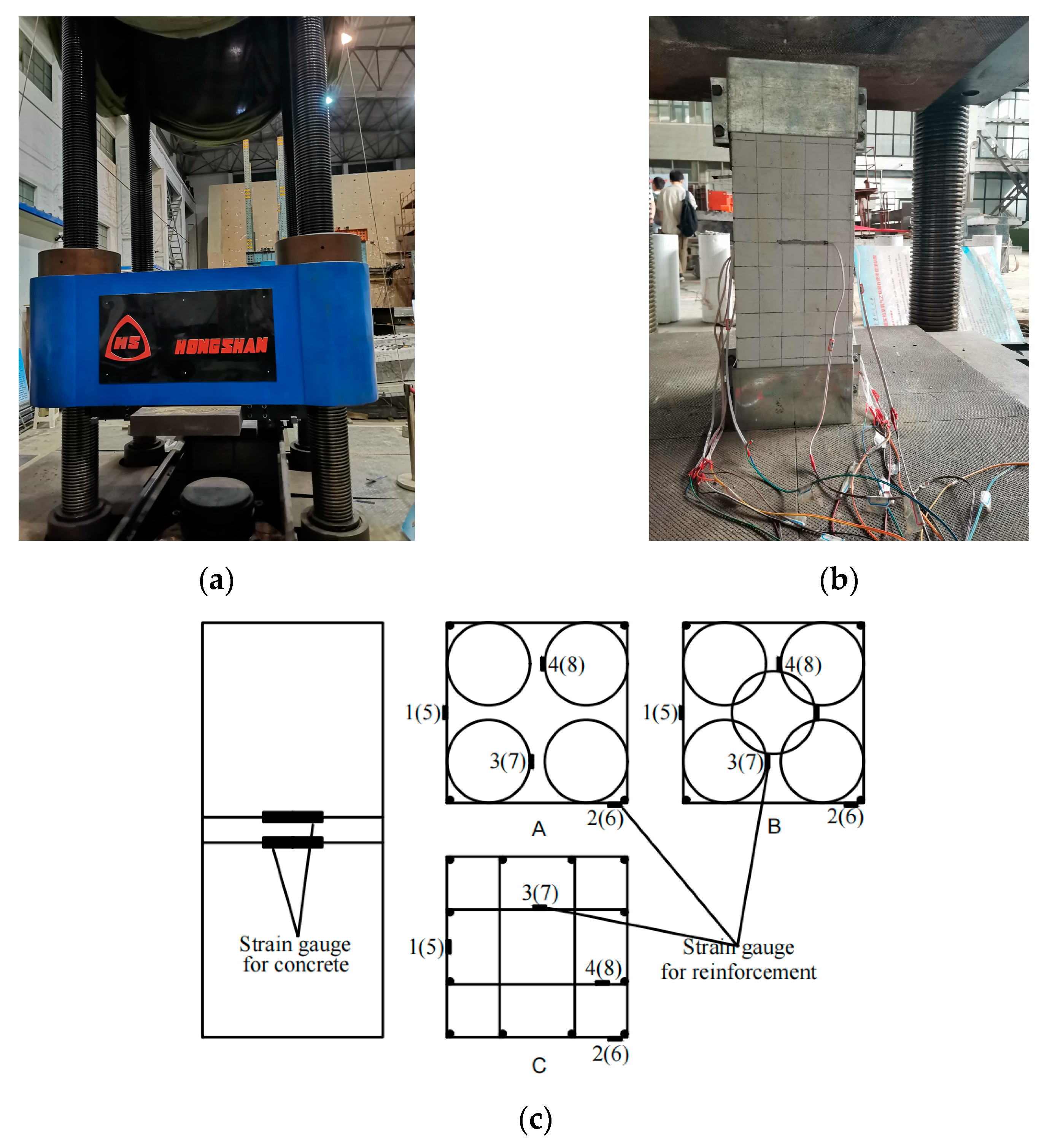
The test was carried out on the 2000 KN hydraulic test machine in the Laboratory. The distribution of devices and measured points is shown in Figure 3. The height range of 450 mm in the middle of the specimen was the test area, and two displacement meters were arranged on the surface of the adjacent sides of the specimen to measure the axial deformation of the specimen. The stirrup strain was measured by attaching a resistance plate to the two rings of the stirrup in the middle of the specimen. This investigation chose the loading way of displacement control, and the loading was stopped when the load value drops to 75% of the peak load.

3.2. Analysis of Strength and Ductility

Table 3 shows the specific data of the test results, where f c c and ε c c represent the peak stress and peak strain of the constrained RC column specimen, respectively. f c o and ε c o are the peak stress and peak strain of the unconstrained RC column specimens, respectively. ε u is the strain of the specimen when the stress of the concrete column specimen decreases to 85% of the peak stress. The increasing multiple of peak stress   K f ( K f = f c c / f c o ), increasing multiple of peak strain K ε ( K ε = ε c c / ε c o ) and ductility ratio μ ε ( μ ε = ε u / ε c c ) can be used as evaluated indicators of the strength and ductility of confined concrete. Comparing specimens A-1 (s = 30 mm), A-2 (s = 50 mm), and A-3 (s = 70 mm), it can be seen that the greater the stirrup spacing, the lower the ascending of peak stress and strain, and the lower the ductility ratio. The increased times of peak stress and strain of specimen A-5 ( f y v = 919 MPa) are 1.15 and 1.66 times that of specimen A-4 ( f y v = 412 MPa), respectively, which means that the higher the stirrups strength, the greater the peak stress and strain. By comparing specimens A-4 and B-1, as well as specimens B-2 and C-1, it can be seen that the strength and ductility of the five-spiral composite stirrup-restrained concrete specimens are significantly better than those of the four-spiral composite stirrup-restrained concrete specimens and slightly better than those of the traditional well-shaped stirrup restrained concrete specimens. The ductility ratio of specimens B-1 and B-2 is the highest (1.98 and 1.97, respectively), which means that the ductility of concrete specimens constrained by a five-spiral composite stirrup is the best in all specimens.
In summary, the strength and ductility of concrete columns confined by multi-spiral composite stirrups are higher than those confined by traditional well-shaped composite stirrups.

3.3. Analysis of Influencing Factors

3.3.1. Stirrup Spacing

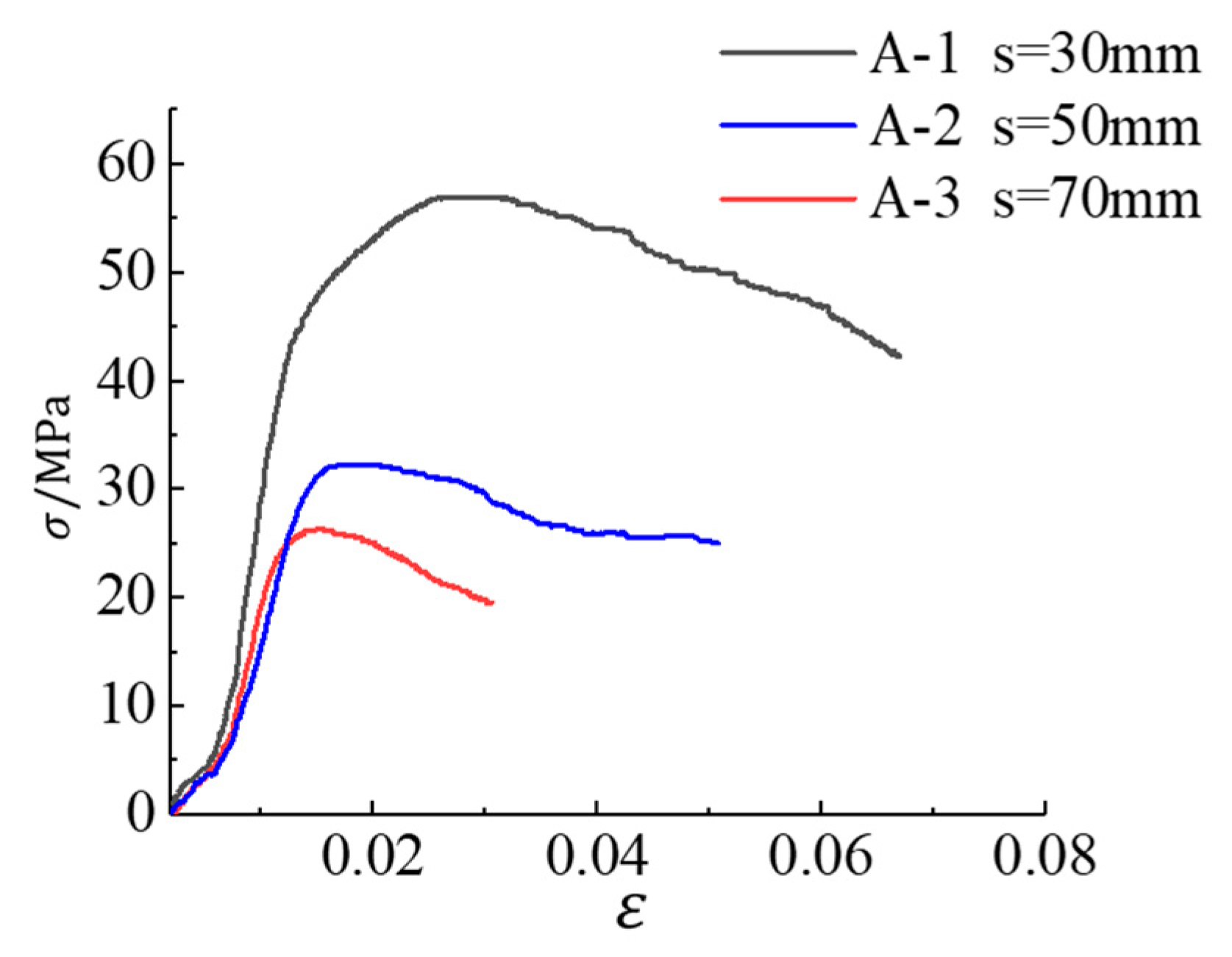
When the stirrup form and strength are the same, the influence of stirrup spacing on the stress–strain curve of the specimen is shown in Figure 4. When the stirrup spacing is 30 mm, the strength of specimen A-1 is significantly increased, and the declining phase of the stress-strain curve is gentle. When the stirrup spacing is 70 mm, the peak strength of specimen A-3 increases slightly, and the declining phase of the stress–strain curve is slightly steep. When the stirrup spacing is 50 mm, the strength and ductility of specimen A-2 are between the former two. Therefore, with the diminution of stirrup spacing, that is, the increase of the ratio of volume stirrup, the carrying capacity and ductility of the specimens are significantly improved, and the deformation ability is also better.

3.3.2. Stirrup Form

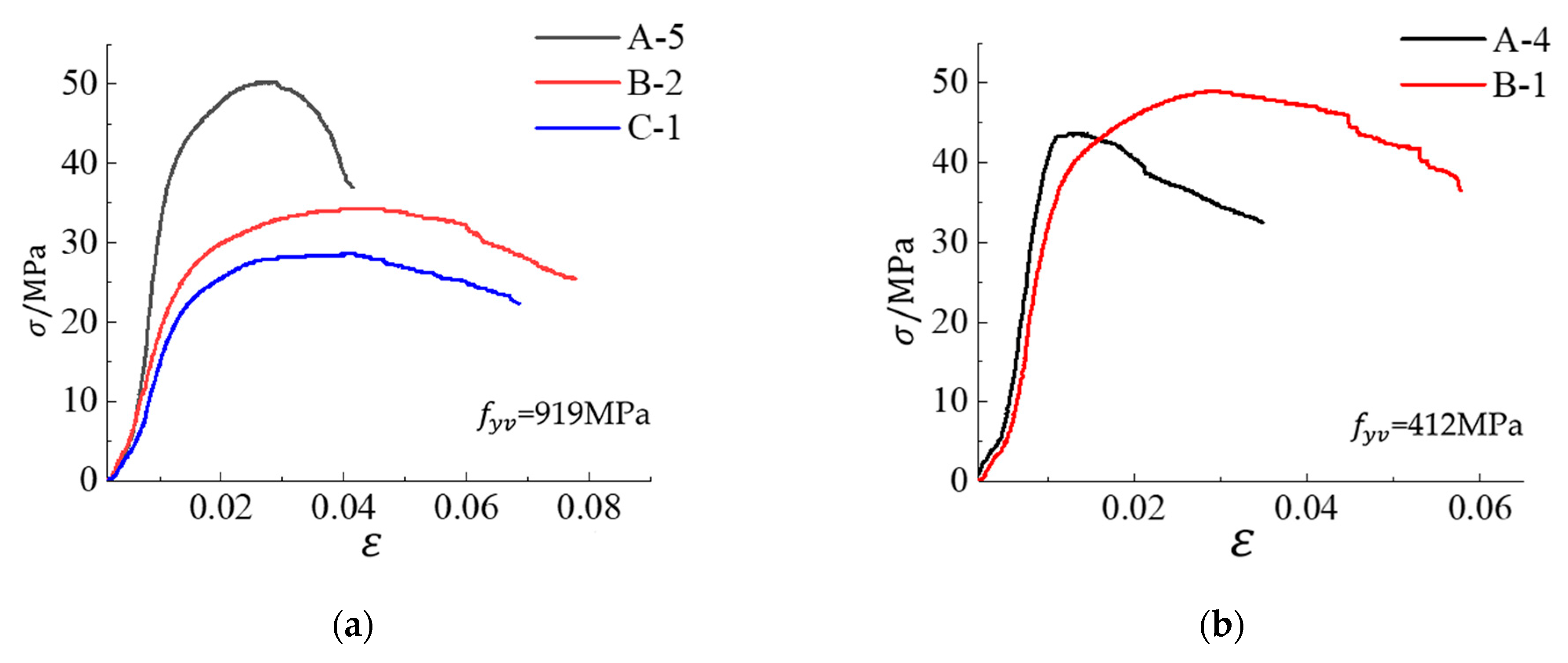
Figure 5 shows the effect of different stirrup types on the stress-strain curves of specimens when the yield strength of the stirrup is 919 MPa and 412 MPa, respectively. According to Figure 5a, when the stirrup strength, spacing, and concrete strength are the same, the restraint effect of the five-spiral composite stirrup form (specimen B-2) is better than that of the well-shaped composite stirrup form (specimen C-1), and the peak strength of the former is higher and the declining phase is more gentle. This is because the small concrete cylinder constrained by the inner spiral hoop is in a state of three-way compression itself, and at the same time is constrained by the outer rectangular hoop. In addition, due to human factors during concrete pouring, the concrete strength of the four-spiral composite stirrup specimen A-5 ( f c = 28.3 MPa) was higher than that of the specimens B-2 and C-1 ( f c = 23.4 MPa). Therefore, the peak strength of the specimen was the highest, but the declining phase of the curve was slightly steeper and the ductility was poor. Figure 5b indicated that the peak strength and strain of specimen B-1 constrained by a five-spiral composite stirrup are significantly larger than those of specimen A-4 constrained by a four-spiral composite stirrup, and the peak plateau of specimen B-1 is longer and the declining phase of the curve is more gentle, that is, the constraint effect of the five-spiral composite stirrup form is better than that of the four-spiral composite stirrup form. This is because the five-spiral composite stirrup interlocks with each other and has a higher degree of constraint.

3.3.3. Stirrup Strength

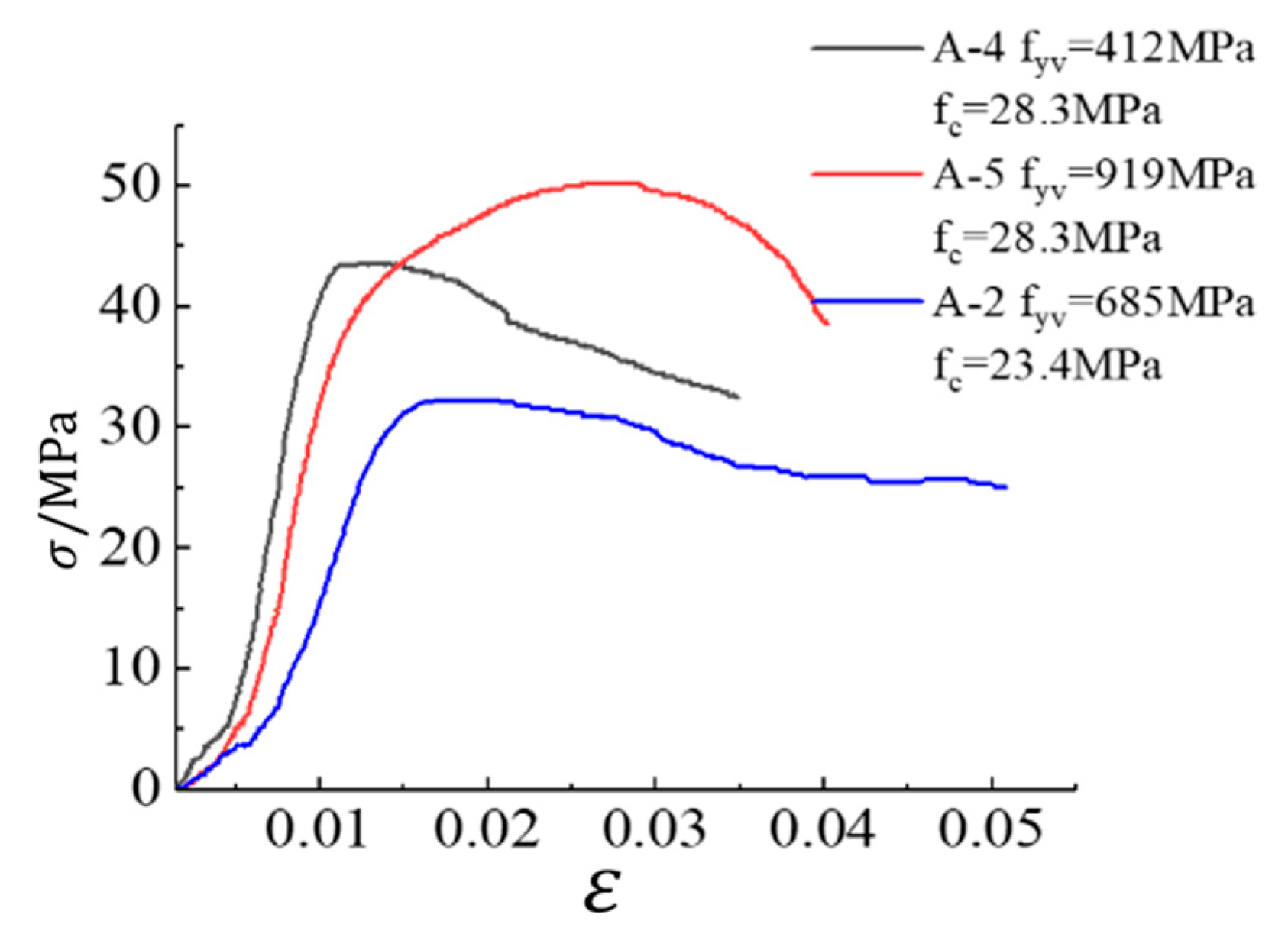
Figure 6 indicates the influence of stirrup strength on the stress–strain curve of the specimen. The peak stress and strain of specimen A-5 ( f y v = 919 MPa) are higher than those of specimen A-4 ( f y v = 412 MPa), and the declining phase of the stress–strain curve of the former specimen is more gentle. So, the strength and ductility of concrete specimens with high-strength stirrup constraints are better than those with ordinary-strength stirrup constraints. In addition, due to the casting problem, the concrete strength of specimen A-2 is relatively low, so the peak strength of its curve in Figure 6 is the lowest, but the descending section is the most gentle.
In summary, the space, form, and strength of a stirrup are important factors affecting the compression performance of concrete columns confined by stirrups. The smaller the stirrup space and the higher the strength, the better the bearing capacity and ductility of the column. And the restraint form of multi-spiral composite stirrups is better than that of traditional well-shaped composite stirrups.

4. Calculation of Stress and Strain

4.1. Analysis of Constraint Mechanism

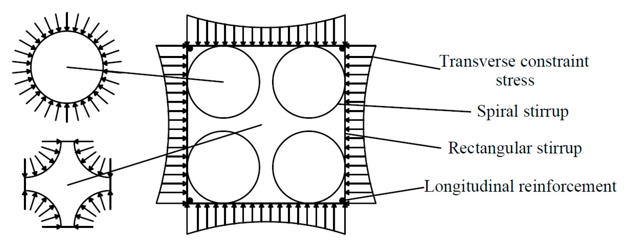
A square RC column confined by four-spiral composite stirrups is taken as an example for analysis. The distribution of constraint stress in its cross-section under axial pressure is shown in Figure 7. The rectangular hoop acts as a transverse constraint on the core concrete surrounded by it, and the distribution of constraint stress is arched along the edge length direction. The four concrete cylinders located inside the four spiral stirrups are confined by both the outer rectangular hoop and the inner spiral stirrups. In addition, the outer rectangular hoop connects the four concrete cylinders together, while allowing the RC cylinders to also provide lateral constraints on the core concrete they enclose.
According to the different degrees of constraint, the cross-section of the square column is divided into three parts: highly constrained region, partially constrained region, and unconstrained region, as shown in Figure 8. The highly constrained region is the area surrounded by four inner spiral hoops. The concrete in this area is constrained by both the outer rectangular hoop and inner spiral hoops. The partially constrained region is the area outside the circular spiral stirrup and inside the rectangular stirrup. The concrete in this area is constrained by the outer rectangular hoop and four concrete cylinders. The unconstrained region is the concrete protective layer.

4.2. Effective Lateral Restraint Stress

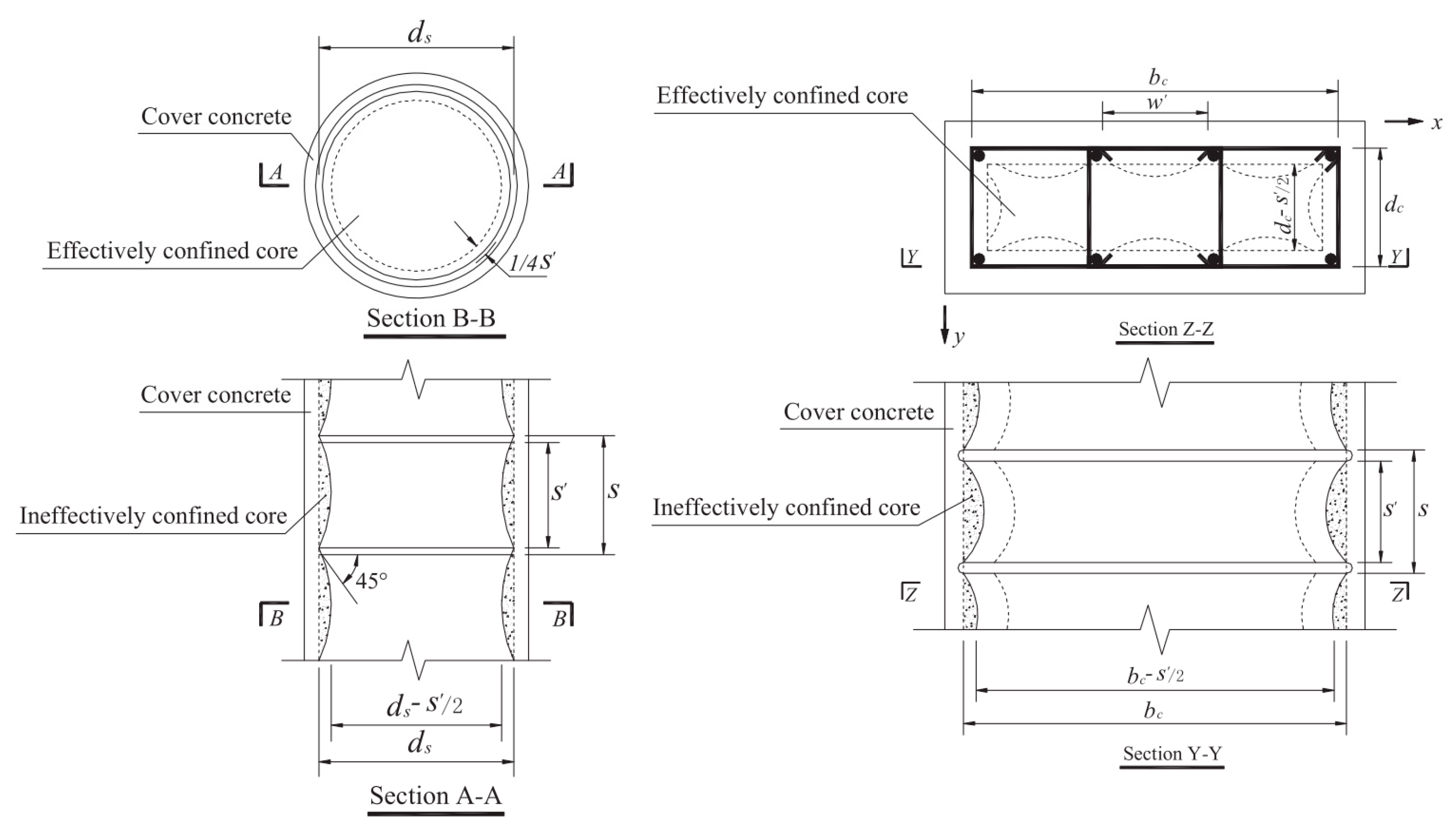
Mader et al. [15] proposed the effective constraint area A e of the circular stirrup and rectangular stirrup (Equations (1) and (2)), and defined the ratio of effective constraint area A e to net core area A c c as the effective constraint coefficient k e . The effective constraint coefficients of circular spiral and rectangular stirrup were calculated in Equations (3) and (4).
A e = π 4 d s 2 1 s 2 d s 2
A e = b c d c i = 1 n w i 2 6 1 s 2 b c 1 s 2 d c
k e 1 = 1 s 2 d s 1 ρ c c
k e 2 = 1 i = 1 n w i 2 6 b c d c 1 s 2 d s 1 s 2 d s 1 ρ c c
where s is the minimum distance between adjacent stirrup surfaces and surfaces. d s is the diameter between the centers of spiral stirrups. b c and d c are the core dimensions of the rectangular stirrup along the x and y orientations of the center line, respectively. w i is the net distance between the ith adjacent lengthways bars. ρ c c is the ratio of the area of lengthways reinforcement to the area of core concrete. The meanings of the above symbols are shown in Figure 9.
The effective lateral constraint stresses f l 1 and f l 2 imposed on concrete by inner spiral hoops and outer rectangular hoops are calculated according to Equations (5) and (6), respectively.
f l 1 = 1 2 k e 1 ρ s f y h 1
f l 2 = 1 2 k e 2 ρ x + ρ y f y h 2
k e 1 and k e 2 in the formula can be calculated according to Equations (3) and (4). ρ s is the volume ratio of the circular spiral stirrup to the internally constrained concrete; ρ x and ρ y are the volume ratios of the rectangular stirrup and its internally constrained concrete in the x and y orientations, respectively. f y h 1 and f y h 2 are stirrup stresses when the confined concrete column under axial load reaches its peak stress, respectively.
For the concrete square column constrained with multi-spiral composite stirrup studied in this paper, its effective constraint stress f l is calculated according to Equation (7) [42], where γ is the ratio of the region of constrained concrete to the region of core concrete in the circular spiral stirrup region.
f l = f l 1 + f l 2 γ + f l 2 1 γ

4.3. Peak Stress

The William–Warnke five-parameter model [43] is used as the failure criterion model of concrete under triaxial compression. Equation (8) represents the compression meridian, and σ o c t and τ o c t represent the octahedral normal stress and tangential stress, respectively.
τ o c t f c o = b 0 + b 1 σ o c t f c o + b 2 σ o c t f c o 2
It is assumed that the transverse constraint stresses of concrete confined by multi-spiral stirrups are equal, where both two principal stresses are transverse constraint stresses and the third stress is compressive strength subjected to maximum load. Then the three principal stresses of constrained concrete can be expressed by Equations (9) and (10).
σ 1 = σ 2 = f l
σ 3 = f c c
The stress is transformed from a Cartesian coordinate system to an octahedral coordinate system to modify the stress, as shown in Equations (11) and (12).
σ o c t = σ 1 + σ 2 + σ 3 3 = f c c 3 2 3 f l
τ o c t = σ 1 2 + σ 2 2 + σ 3 2 3 σ o c t 2 = 2 3 f c c f l
By substituting Equations (11) and (12) into Equation (8), the formula for calculating the peak stress of constrained concrete f c c can be obtained as follows:
f c c = f c o 3 2 + b 1 2 b 2 + 3 2 + b 1 2 b 2 2 9 b 0 b 2 9 2 f l b 2 f c o 2 f l f c o
where f l is the effective constraint stress; f c o is the peak stress of unconstrained concrete; b 0 , b 1 , and b 2 are the coefficients. By regression analysis of the experimental data in this investigation, b 0 = 0.111, b 1 = −1.02, and b 2 = −0.304 are obtained, and their values are put into Equation (13) to obtain the formula (Equation (14)) for calculating the peak stress of constrained concrete suitable for this paper.
f c c = f c o 1.944 + 2.663 1 + 5.9 f l f c o 2 f l f c o
Table 4 indicates the experimental value of the peak stress of the square RC column with multi-spiral composite stirrups tested in this paper and the theoretical value calculated according to the above equations. Through comparative analysis, it can be seen that the calculated value is generally higher than the tested value. The error ω is defined as the ratio of the calculated value minus the tested value to the tested value. The maximum ω is 6.844%, the minimum ω is 0.797%, and the average ω is 3.910%. Therefore, Formula (14) has a high accuracy when it is used to calculate the peak stress of concrete confined by multi-spiral composite stirrups.

4.4. Peak Strain

According to the formula presented by Bing et al. and combined with the regression analysis of the experimental data in this investigation, the calculation formula of peak strain ε c c is as follows:
ε c c ε c o = 1 + 18.92 f l f c o 0.58
Table 5 shows the experimental values of the peak strain of concrete square columns with multi-spiral composite stirrup tested in this paper and the theoretical values calculated according to the above equation. Through comparative analysis, it can be seen that the maximum ω is 9.510%, the minimum ω is 0.260%, and the average ω is 5.621%. Therefore, Equation (15) can be used to calculate the peak strain of concrete with multi-spiral composite stirrup constraints.

4.5. Ultimate Compressive Strain

In this paper, the strain value corresponding to the axial load of the constrained concrete square column falling to 85% of the peak value is taken as the ultimate compressive strain ε c u . Through regression analysis of the test data, the calculation formula of the ultimate compressive strain ε c u can be obtained as follows:
ε c u ε c o = 2 + 41.81 f l f c o 0.76
Table 6 shows the test values of the ultimate compressive strain of the square RC column confined by multi-spiral composite stirrups tested in this paper and the theoretical values calculated according to the above equation. Through comparative analysis, it can be seen that the maximum ω is 17.743%, the minimum ω is 1.376%, and the average ω is 8.484%. For specimen B-1, although the maximum error ω between the test value and the calculated value was more than 10%, the calculation was safe because the calculated value was less than the test value, so the corresponding formula could be used.

4.6. Stirrup Stress

The test in this paper shows that when the stress of the concrete column confined by the multi-spiral composite stirrups reaches the peak stress, the high-strength stirrup does not yield completely. If the yield strength of the stirrup is used to calculate the effective lateral constraint stress, the calculation result will be too large. Therefore, the actual stress of the transverse stirrup when the column reaches the peak stress should be used to calculate the effective lateral constraint stress. Cusson gave a simplified formula to calculate the actual stress f y h of high-strength stirrup under peak stress, as follows:
ε h c = 0.5 ε c c 1 f l f c c
At the same time, the iterative process of calculating the actual strain ε h c and stress f y h of the high-strength stirrup is given:
  • Let f y h = f y and substitute them into Equations (5) and (6) to find the effective lateral constraint stresses f l 1 and f l 2 imposed on concrete by inner spiral hoops and outer rectangular hoops;
  • Substitute f l 1 and f l 2 into Equation (7) to calculate the effective transverse constraint stress f l of high-strength stirrup on core concrete;
  • Substitute f l into Equations (14) and (15), respectively, to calculate the peak stress f c c and peak strain ε c c ;
  • By substituting f l , f c c and ε c c into Equation (17), the strain ε h c of the high-strength stirrup is obtained;
  • The stress f y h of the high-strength stirrup is gained by the stress-strain relation of high-strength stirrup;
  • Only when the f y h < f y , the calculated value of f y h is re-substituted into step1 to recalculate the relevant parameters;
  • Repeat steps 2 to 6 until convergence.
In summary, based on the analysis of the constraint mechanism, the effective lateral constraint coefficient f l is introduced to establish the formulas for calculating the peak stress f c c , peak strain ε c c , and ultimate compressive strain ε c u of concrete confined by multi-spiral composite stirrups. In addition to this, the iterative formulas for calculating the actual stress and strain of stirrups are given.

5. Constitutive Model

5.1. Establishment of Constitutive Model

At the beginning of loading, the passive constraint of stirrups and compressive strain of concrete are small, and the existing constitutive models of constrained concrete at home and abroad have little difference in the rising section. However, after the peak stress, due to the great difference in the effect of different constraints, different constraints of concrete constitutive models will differ greatly in the vicinity of the peak stress and its declining section. In this paper, the corresponding constitutive model is proposed for concrete confined by multi-spiral composite stirrups, as shown in Equations (18)–(20). The stress-strain relation curve is shown in Figure 10. The curve equation of the Bing constitutive model is adopted in the ascending section. The declining section is a straight line whose slope is determined by the peak point and the point where the stress drops to 0.85   f c c . The stress is assumed to remain constant after decreasing to 0.4   f c c .
0 < ε c ε c o   :                 f c = E c ε c + f c o E c ε c ε c o 2 ε c 2
ε c o < ε c ε c c   : f c = f c c ε c ε c c 2 ε c c ε c o 2 f c c f c o
ε c c < ε c   :           f c = f c c 1 0.15 ε c ε c c ε 85 ε c c
In the formula, ε c c   and f c c are calculated by Equations (14) and (15), respectively. ε 85 represents the strain when it drops to 85% of the peak stress, and can be calculated by Equation (16).

5.2. Comparative Analysis of Constitutive Models

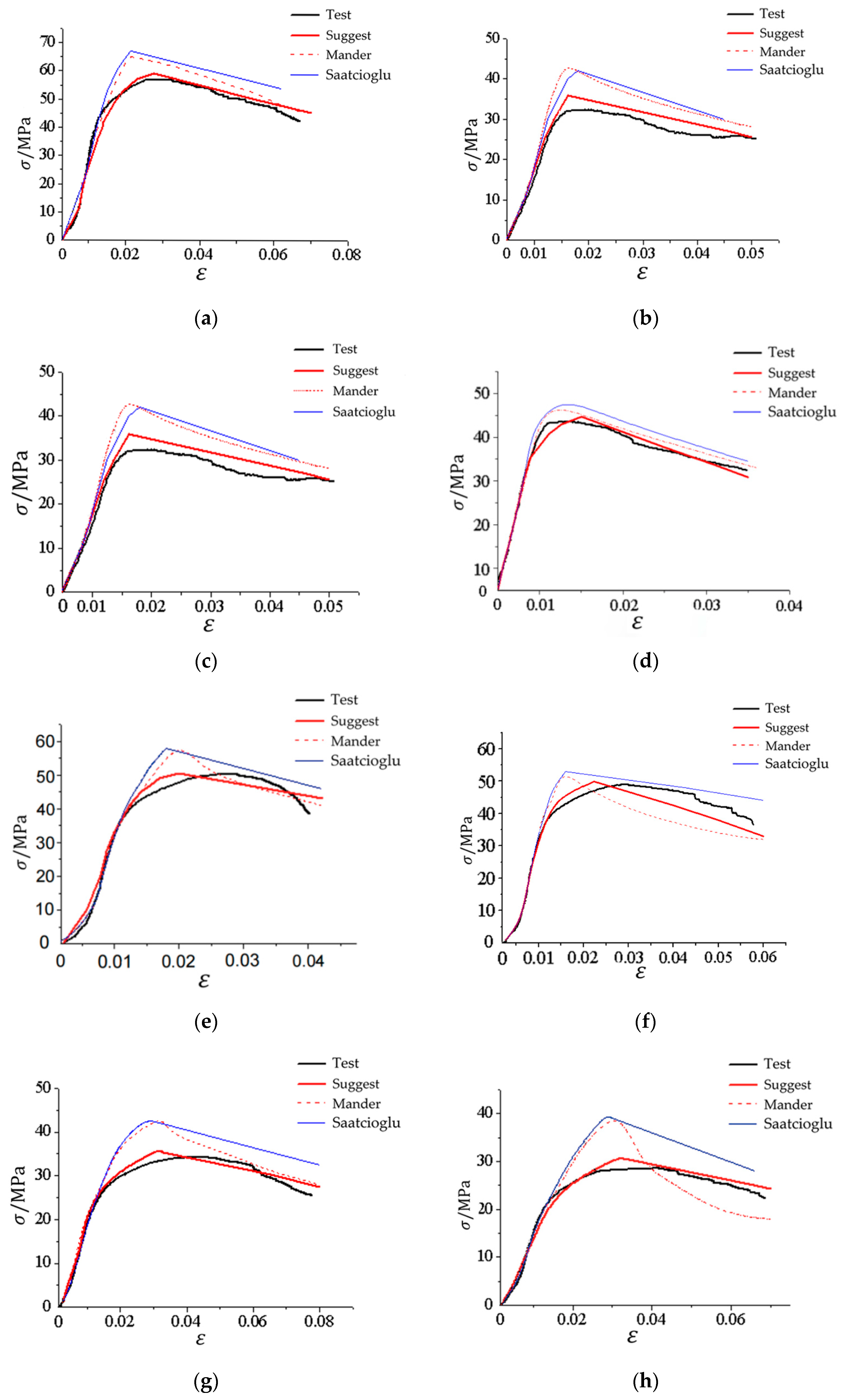
For the specimens tested in this paper, the Mander model [15], the Saatcioglu model [18], and the constitutive model presented by this paper were respectively used to calculate the corresponding stress–strain curves and compared with the test curves in Figure 11. The differences between the rising section of the stress–strain curve calculated by each model and the test curve are small. However, the peak stress, strain, and declining section of the curves are quite different, and the calculation results of the Mander model and Saatcioglu model are higher. The main reason is that the yield strength of the high-strength stirrup is used in the calculation of the peak point, while the actual stress of the stirrup does not reach the yield. The calculation curve of the presented model fits well with the test curve, so the model can be used to predict the stress–strain relation curve of concrete confined by multi-spiral composite stirrups.
In summary, based on the theoretical analysis and experimental data, the stress-strain curves and corresponding piecewise equations of concrete confined by multi-spiral stirrups are established. The results can be used as a reference for the numerical simulation and engineering design of such components.

6. Conclusions

Based on the axial compression test of seven multi-spiral composite stirrups square RC columns and 1 traditional well-shaped composite stirrups square RC column, the following conclusions are obtained:
  • With the decrease of stirrup spacing or the increase of stirrup strength, the carrying capacity and ductility of the specimens are significantly improved, and the deformation ability is also better. The strength and ductility of the square RC column specimen confined by five-spiral composite stirrups are obviously better than those of the corresponding specimens with four-spiral composite stirrups, and slightly better than those of the corresponding specimen with traditional well-shaped composite stirrups.
  • The restraint mechanism of multi-spiral composite stirrups was analyzed. According to the different degrees of constraint, the cross-section of the square RC column is divided into three areas: the highly constrained region (the area surrounded by the circular spiral stirrups), the partially constrained region (the area outside the circular spiral stirrups and the area within the rectangular hoop) and the unconstrained region (the protective layer).
  • Combined with theoretical analysis and experimental data regression, the formulas of effective confinement stress, peak stress, peak strain, and ultimate strain of concrete confined by multi-spiral composite stirrups are proposed and compared with the experimental results. The results show that the error between the calculated and experimental values is less than 5%, which means the calculation formula presented in this paper has high accuracy.
  • A constitutive model of concrete confined by multi-spiral composite stirrups is proposed and compared with several typical constitutive models of constrained concrete. The results indicate that the presented constitutive model fits well with the experimental curve and can predict the axial compression performance of this type of constrained concrete well.

7. Discussion

According to the test results of this paper, the strength and ductility of concrete columns can be significantly improved by considering the form of cross-section reinforcement restrained by four or five spiral stirrups in practical engineering. In particular, the formulas of effective confining stress, peak stress, peak strain, and ultimate strain proposed in this paper can be used in the design of multi-spiral composite stirrup-constrained concrete columns. Due to the influence of the number of specimens and production errors, it is not possible to fully analyze the influence of each parameter on the constraint effect of specimens. Therefore, the finite element method will be used to simulate the mechanical properties of such components, and the rationality of the constitutive model proposed in this paper will be compared and analyzed.

8. Recommendations

In this paper, experimental research and theoretical analysis are carried out on the axial compression performance and constitutive model of confined concrete short columns confined by multi-spiral composite stirrups, but the analysis of the influencing factors is not comprehensive, such as the size effect, concrete strength, stirrup form optimization, and so on. In addition, further experimental studies are needed on the optimal design of axial compression, the partial compression performance, and the seismic performance of the concrete columns confined by multi-spiral composite stirrups, which can provide a theoretical basis for the practical engineering application of this type of column.

Author Contributions

Conceptualization, K.Y.; methodology, K.Y. and S.S.; software, J.Z.; validation, G.M. and J.Z.; formal analysis, T.Y.; investigation, T.Y. and G.M.; resources, K.Y.; data curation, G.M.; writing—original draft preparation, T.Y.; writing—review and editing, K.Y. and S.S.; visualization, T.Y.; supervision, K.Y.; project administration, T.Y. and S.S.; funding acquisition, K.Y. All authors have read and agreed to the published version of the manuscript.

Funding

This research was funded by National Natural Science Foundation of China, grant number 51708035; by Fundamental Research Funds of the Central Universities, grant number 300102289202; and by Natural Science Basic Research Plan in Shaanxi Province of China, grant number 2021JM-177.

Data Availability Statement

In all datasets presented in this study are included in the article.

Conflicts of Interest

The authors declare no conflict of interest.

References

  1. Ye, L.P.; Lu, X.Z.; Zhao, S.C. Analysis on seismic damage of buildings in the Wenchuan earthquake. J. Build. Struct. 2008, 29, 1–9. [Google Scholar] [CrossRef]
  2. Li, H.N.; Xiao, S.Y.; Huo, L.S. Damage investigation and analysis of engineering structures in the Wenchuan earthquake. J. Build. Struct. 2008, 29, 10–19. [Google Scholar] [CrossRef]
  3. Chen, Z.; Chen, J.; Jiang, X.; Mo, L. Experimental research and finite element analysis on seismic behavior of square reinforced concrete columns with four interlocking spirals. Structures 2022, 39, 1–16. [Google Scholar] [CrossRef]
  4. Yang, L.G.; Wang, Y.Y.; Liew, J.Y.R. Compression-Bending Strength Model for Corrugated Steel Tube Confined Reinforced Concrete Section. J. Struct. Eng. 2021, 147, 04021187. [Google Scholar] [CrossRef]
  5. Qaidi, S.; Al-Kamaki, Y.S.S.; Al-Mahaidi, R.; Mohammed, A.S.; Ahmed, H.U.; Zaid, O.; Althoey, F.; Ahmed, J.; Isleem, H.F.; Bennetts, I. Investigation of the effectiveness of CFRP strengthening of concrete made with recycled waste PET fine plastic aggregate. PLoS ONE 2022, 17, e0269664. [Google Scholar] [CrossRef]
  6. Ahmed, M.; Sheikh, M.N.; Hadi, M.N.S.; Liang, Q.Q. Nonlinear analysis of square spiral-confined reinforced concrete-filled steel tubular short columns incorporating novel confinement model and interaction local buckling. Eng. Struct. 2022, 274, 115168. [Google Scholar] [CrossRef]
  7. Zhao, D.; Zhang, J.; Lu, L.; Liang, H.; Ma, Z. The Strength in Axial Compression of Aluminum Alloy Tube Confined Concrete Columns with a Circular Hollow Section: Experimental Results. Buildings 2022, 12, 699. [Google Scholar] [CrossRef]
  8. Wei, Y.; Xu, Y.; Wang, G.; Cheng, X.; Li, G. Influence of the Cross-Sectional Shape and Corner Radius on the Compressive Behaviour of Concrete Columns Confined by FRP and Stirrups. Polymers 2022, 14, 341. [Google Scholar] [CrossRef]
  9. Hao, M.J.; Zheng, W.Z.; Chang, W. Compression behavior of reinforced concrete columns jacketed with multi-spiral transverse reinforcement. Struct. Concr. 2022, 26, 2942–2967. [Google Scholar] [CrossRef]
  10. Chen, Z.P.; Zhou, J.; Jing, C.G.; Tan, Q.H. Mechanical behavior of spiral stirrup reinforced concrete filled square steel tubular columns under compression. Eng. Struct. 2021, 226, 19. [Google Scholar] [CrossRef]
  11. Eid, R.; Cohen, A.; Guma, R.; Ifrach, E.; Levi, N.; Zvi, A. High-Strength Concrete Circular Columns with TRC-TSR Dual Internal Confinement. Buildings 2019, 9, 218. [Google Scholar] [CrossRef] [Green Version]
  12. Wang, Q.X.; Zhao, G.F.; Lin, L.Y. Experimental study on ductility of high strength concrete columns. J. Build. Struct. 1995, 16, 22–31. [Google Scholar] [CrossRef]
  13. Sheikh, S.A.; Uzumeri, S.M. Analytical model for concrete confinement in tied columns. J. Struct. Eng. 1982, 108, 2703–2722. [Google Scholar] [CrossRef]
  14. Mander, J.B. Seismic Design of Bridge Piers. Ph.D. Thesis, University of Canterbury, Christchurch, New Zealand, 1983. [Google Scholar] [CrossRef]
  15. Mander, J.B.; Priestley, J.N.; Park, R. Theoretical stress-strain model for confined concrete. J. Struct. Eng. 1988, 114, 1804–1826. [Google Scholar] [CrossRef] [Green Version]
  16. Cusson, D.; Paultre, P. High-strength concrete columns confined by rectangular ties. J. Struct. Eng. 1994, 120, 783–804. [Google Scholar] [CrossRef]
  17. Cusson, D.; Paultre, P. Stress-strain model for confined high-strength concrete. J. Struct. Eng. 1995, 121, 468–477. [Google Scholar] [CrossRef]
  18. Saatcioglu, M.; Razvi, S.R. Strength and ductility of confined concrete. J. Struct. Eng. 1992, 118, 1590–1607. [Google Scholar] [CrossRef]
  19. Bing, L.; Park, R.; Tanaka, H. Stress-strain behavior of high-strength concrete confined by ultra-high- and normal-strength transverse reinforcements. J. Struct. Eng. 2001, 98, 395–406. [Google Scholar]
  20. Rong, C.; Shi, Q. Analysis constitutive models for actively and passively confined concrete. Compos. Struct. 2021, 256, 113009. [Google Scholar] [CrossRef]
  21. Li, Y.Z.; Cao, S.Y.; Jing, D.H. Axial compressive behaviour of RC columns with high-strength MTS transverse reinforcement. Mag. Concr. Res. 2017, 69, 436–452. [Google Scholar] [CrossRef]
  22. Li, Y.Z.; Cao, S.Y.; Jing, D.H. Analytical compressive stress-strain model for concrete confined with high-strength multiple-tied-spiral transverse reinforcement. Struct. Des. Tall Spec. Build. 2018, 27, e1416. [Google Scholar] [CrossRef]
  23. Shi, Q.X.; Yang, K.; Liu, W.Y.; Zhang, X.H.; Jiang, W.S. Experimental study on mechanical behavior of high strength concrete confined by high-strength stirrups under concentric loading. Eng. Mech. 2012, 29, 141–149. [Google Scholar]
  24. Yang, K.; Shi, Q.X.; Zhao, J.H.; Jiang, W.S.; Meng, H. Study on the constitutive model of high-strength concrete confined by high-strength stirrups. China Civ. Eng. J. 2013, 46, 34–41. [Google Scholar] [CrossRef]
  25. Ouyang, X.; Wu, Z.M.; Shan, B.; Chen, Q.; Shi, C.J. A critical review on compressive behavior and empirical constitutive models of concrete. Constr. Build. Mater. 2022, 323, 126572. [Google Scholar] [CrossRef]
  26. Zheng, W.Z.; Zhang, J.; Wang, G.; Wang, Y. Experimental Study on Axial Compression Behavior of High- strength Concrete Columns Confined by Spiral Stirrups. China J. Highw. Transp. 2022, 35, 22–35. [Google Scholar] [CrossRef]
  27. Jin, L.; Li, P.; Du, X.L. Compressive stress-strain model for stirrup-confined concrete columns considering the effect of structural size. J. Civ. Environ. Eng. 2020, 42, 81–89. [Google Scholar] [CrossRef]
  28. Li, M.H.; Zhou, W.; Liu, M.J.; Liu, G.Y.; Zhang, S. Experimental investigation of reinforced concrete columns with composite spiral stirrups under eccentric loading. J. Harbin Inst. Technol. 2019, 51, 113–120. [Google Scholar] [CrossRef]
  29. Yin, Y.L. Researches and developments of alternative confinements for rectangular concrete columns (I). China Civ. Eng. J. 2004, 37, 1–10. [Google Scholar] [CrossRef]
  30. Yin, Y.L. Researches and developments of alternative confinements for rectangular concrete columns (II). China Civ. Eng. J. 2004, 37, 1–12. [Google Scholar] [CrossRef]
  31. Yin, Y.L.; Weng, Z.Q.; Wang, R.Z.; Liang, J.Y. Axial compressive behavior of precast SRC columns with multi-spirals. Eng. Sci. 2006, 8, 16–30. [Google Scholar]
  32. Yin, Y.L.; Wu, T.L.; Liu, T.C.; Sheikh, S.A.; Wang, R. Interlocking spiral confinement for rectangular columns. Concr. Int. 2011, 33, 38–45. [Google Scholar]
  33. Yin, Y.L.; Wang, J.C.; Wang, P.H. Development of multi-spiral confinements in rectangular columns for construction automation. J. Chin. Inst. Eng. 2012, 35, 309–320. [Google Scholar] [CrossRef] [Green Version]
  34. Hung, H.H.; Wang, P.H.; Yin, Y.L.; Wang, J.C.; Chang, K.C. Large-scale cyclic loading test on a multi-spiral stirrup bridge pier constructed by automated method. In Proceedings of the 15th World Conference on Earthquake Engineering, Lisbon, Portugal, 24–28 September 2012. [Google Scholar]
  35. Chen, Y.; Feng, J.; Yin, S. Compressive behavior of reinforced concrete columns confined by multi-spiral hoops. Comput. Concr. 2012, 9, 359–373. [Google Scholar] [CrossRef]
  36. Weng, C.C.; Yin, Y.L.; Wang, J.C.; Liang, C.Y. Seismic cyclic loading test of SRC columns confined with 5-spirals. Sci. China Series E-Tech. Sci. 2008, 51, 529–555. [Google Scholar] [CrossRef]
  37. Shih, T.H.; Chen, C.C.; Weng, C.C.; Yin, Y.L.; Wang, J.C. Axial strength and ductility of square composite columns with two interlocking spirals. J. Constr. Steel Res. 2013, 90, 184–192. [Google Scholar] [CrossRef]
  38. Wu, T.L.; Ou, Y.C.; Yin, Y.L.; Wang, J.C.; Wang, P.H.; Ngo, S.H. Behavior of oblong and rectangular bridge columns with conventional tie and multi-spiral transverse reinforcement under combined axial and flexural loads. J. Chin. Inst. Eng. 2013, 36, 980–993. [Google Scholar] [CrossRef]
  39. Tang, Q.; Li, Y.; Lu, X.Z.; Yan, W.M. Study on axial compression capacity of multi-spiral hoops confined concrete columns. Eng. Mech. 2018, 35, 166–171. [Google Scholar] [CrossRef]
  40. Wang, P.-H.; Chang, K.-C.; Yin, S.Y.-L.; Wang, J.-C.; Ou, Y.-C. Simplified Finite-Element Analysis Method for Axial Compression Behavior of Rectangular Concrete Columns with Interlocking Multispiral Reinforcements. J. Struct. Eng. 2020, 146, 04019176. [Google Scholar] [CrossRef]
  41. Yang, K.; Guo, S.H.; Wang, Y.K.; Liu, R.; Hu, Y.Y. Experimental study on axial compression performance of square concrete column confined with new multi-spiral composite stirrup. J. Archit. Civ. Eng. 2021. [Google Scholar]
  42. Kim, J.K.; Park, C.K. The behaviour of concrete columns with interlocking spirals. Eng. Struct. 1999, 21, 945–953. [Google Scholar] [CrossRef]
  43. Willam, K.J. Constitutive model for the triaxial behaviour of concrete. Proc. Intl. Assoc. Bridge Structl. Engrs. 1975, 19, 1–30. [Google Scholar]
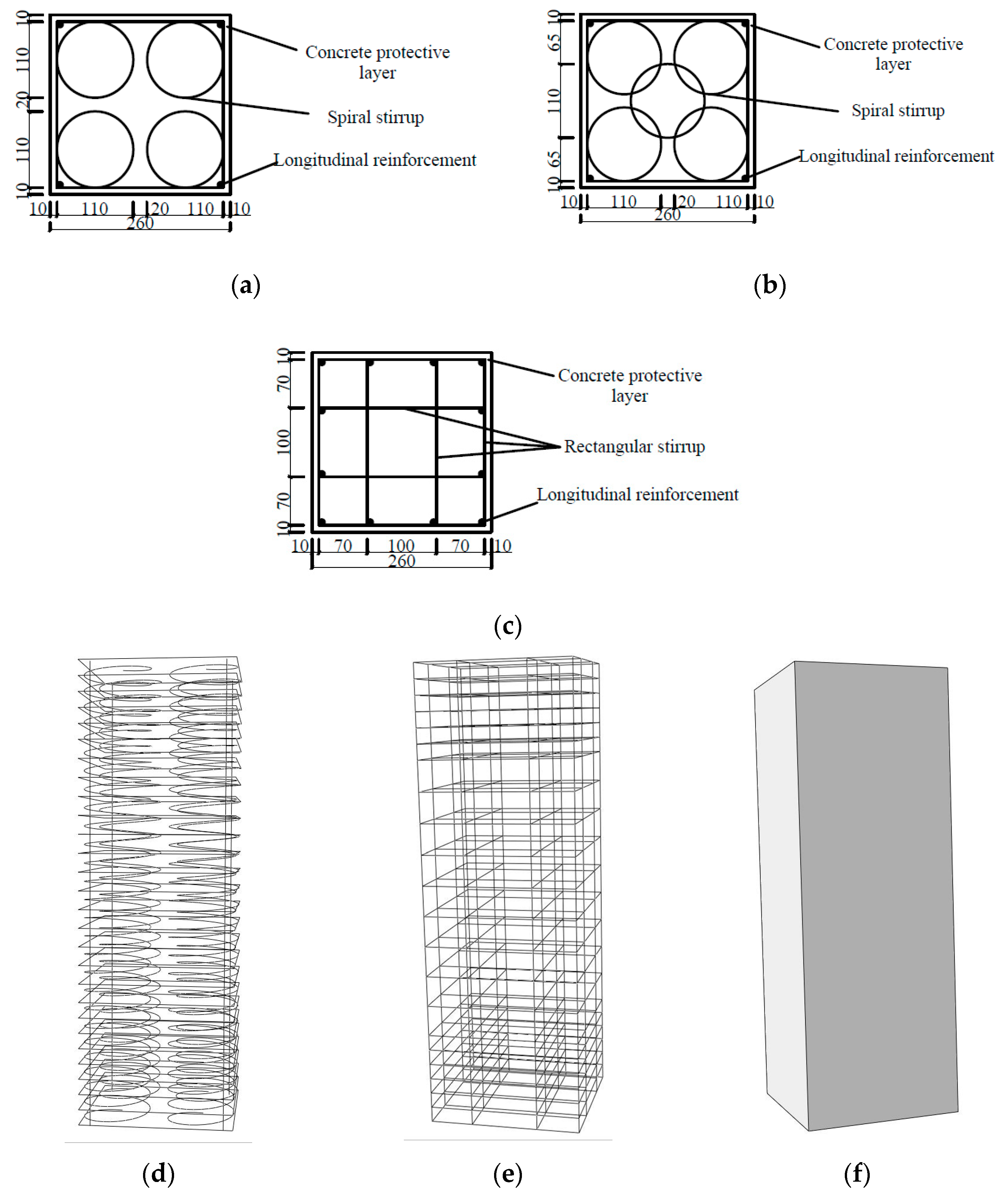
Figure 1. Specimen size and stirrup form. (a) four-spiral composite stirrups; (b) five-spiral composite stirrups; (c) traditional well-shaped composite stirrups; (d) 3d diagram of four-spiral composite stirrups; (e) 3d diagram of traditional well-shaped composite stirrups; (f) A geometric model of confined concrete column.
Buildings 12 02179 g001
Figure 2. The main production process of constrained concrete column specimen. (a) Binding the steel cage; (b) Building formwork on the outside of the steel cage; (c) Vibrating concrete. (d) Attaching strain gauge to concrete surface.
Buildings 12 02179 g002
Figure 3. Distribution of loading device and measuring point. (a) 2000 KN hydraulic test machine; (b) Tested specimen; (c) Distribution of strain gauge.
Buildings 12 02179 g003
Figure 4. Influence of stirrup spacing.
Buildings 12 02179 g004
Figure 5. Influence of stirrup form. (a) Stress–strain curves of specimens with different stirrup forms when the stirrup strength is 919 MPa; (b) Stress–strain curves of specimens with different stirrup forms when the stirrup strength is 412 MPa.
Buildings 12 02179 g005
Figure 6. Influence of stirrup strength (Specimen of four-spiral composite stirrup).
Buildings 12 02179 g006
Figure 7. Distribution of transverse constraint stress of square column with four spiral stirrups.
Buildings 12 02179 g007
Figure 8. Division of constrained region of square column with four spiral stirrups.
Buildings 12 02179 g008
Figure 9. Effectively restrained area of transverse reinforcement.
Buildings 12 02179 g009
Figure 10. Stress–strain curve of confined concrete.
Buildings 12 02179 g010
Figure 11. Comparison of stress-strain curves of specimens. (a) Specimen A-1; (b) Specimen A-2; (c) Specimen A-3; (d) Specimen A-4; (e) Specimen A-5; (f) Specimen B-1; (g) Specimen B-2; (h) Specimen C-1.
Buildings 12 02179 g011
Table 1. Design parameters of specimen.
Specimen No.Stirrup FormStirrup Yield Strength
/MPa
Stirrup Spacing
/mm
Ratio of Volume Hoop ρ v /% f c u
/MPa
f c
/MPa
A-1A685306.3137.324.9
A-2A685503.9630.820.6
A-3A685702.7930.820.6
A-4A412503.9637.324.9
A-5A919503.9637.324.9
B-1B412504.5337.324.9
B-2B919504.5330.820.6
C-1C919503.9630.820.6
Table 2. Mechanical properties of reinforcement.
TypeDiameter
/mm
Yield Strength
f y v /MPa
Elastic Modulus
E/105
HRB40084122.0
HTRB63086852.0
1000 MPa89192.0
Table 3. Test result.
Specimen No. f c c /MPa ε c c ε u μ ε K f K ε
A-156.90.028030.054731.952.2914.02
A-233.40.019210.033431.741.629.61
A-326.30.016860.024721.471.288.43
A-443.60.014080.022701.611.757.04
A-550.20.023400.038411.642.0211.7
B-150.00.024710.048921.982.0112.36
B-234.30.035080.068941.971.6717.54
C-128.40.035210.061051.731.3817.61
Table 4. Tested and calculated values of peak stress.
Specimen No.Tested Value/MPaCalculated Value/MPa ω = C a l c u l a t e d   v a l u e     T e s t e d   v a l u e T e s t e d   v a l u e /%
A-156.958.93.515
A-233.436.07.784
A-326.328.16.844
A-443.644.72.523
A-550.250.60.797
B-150.049.8−4.000
B-234.335.94.665
C-128.431.09.155
Average value of ω 3.910
Table 5. Tested and calculated values of peak strain.
Specimen No.Tested Value/MPaCalculated Value/MPaω  = C a l c u l a t e d   v a l u e     T e s t e d   v a l u e T e s t e d   v a l u e /%
A-10.028030.02760−1.534
A-20.019210.019260.260
A-30.016860.01529−9.312
A-40.014080.015036.747
A-50.023400.02280−2.564
B-10.024710.02236−9.510
B-20.035080.03185−9.208
C-10.035210.03201−9.088
Average value of ω 5.621
Table 6. Tested and calculated values of ultimate compressive strain.
Specimen No.Tested Value/MPaCalculated Value/MPaω  = C a l c u l a t e d   v a l u e     T e s t e d   v a l u e T e s t e d   v a l u e /%
A-10.054730.05410−1.151
A-20.033430.033891.376
A-30.024720.025222.023
A-40.022700.024688.722
A-50.038410.042169.763
B-10.048920.04024−17.743
B-20.068940.06530−5.280
C-10.061050.065707.617
Average value of ω 8.484
Publisher’s Note: MDPI stays neutral with regard to jurisdictional claims in published maps and institutional affiliations.