Article

Adaptive Passive-Control for Multi-Stage Seismic Response of High-Rise Braced Frame Using the Frictional-Yielding Compounded BRBs

1
Faculty of Infrastructure Engineering, Dalian University of Technology, Dalian 116024, China
2
College of Civil and Transportation Engineering, Hohai University, Nanjing 210098, China
3
School of Civil Engineering, Harbin Institute of Technology, Harbin 150001, China
*
Author to whom correspondence should be addressed.
Buildings 2022, 12(12), 2123; https://doi.org/10.3390/buildings12122123
Submission received: 12 October 2022 / Revised: 21 November 2022 / Accepted: 28 November 2022 / Published: 2 December 2022
(This article belongs to the Section Building Structures)

Abstract

:
Buckling-restrained brace (BRB) is a dual-function device that improves the seismic resistance and energy-dissipation capacity of structures in earthquake engineering. To achieve the expected performance under severe ground motions, BRB is usually designed to remain elastic under mild earthquakes, leading to the increased seismic forces and insignificant vibration-reduction effect on the structures at this stage. This study extends the concept of adaptive passive-control of structures by proposing a novel frictional-yielding compounded BRB (FBRB). FBRB is fabricated by connecting the BRB steel casing and end plates with the friction dampers (FDs) in such a way that the BRB steel core and FDs undergo compatible deformation. In this way, FD dissipates seismic energy under mild earthquakes, while FD together with the BRB core dissipates energy under severe ground motions, resulting in an efficient self-adaptive vibration-reduction mechanism. The proposed FBRB construction was experimentally validated by carrying out the reversed-cyclic test, and the result indicated reliable connection with stable hysteretic behavior. Subsequently, the FBRB-equipped frame was proposed and studied which adopted FBRB as the energy-dissipative devices. A parametric design method was developed to determine the FBRB parameters with which the maximum elastic drift of the system could be reduced to the code-allowable value. The approach was implemented on a 48-story mega FBRB-equipped steel frame as the case study. The seismic behavior of the FBRB-equipped case structure was compared with that of the BRB-equipped system, and critically evaluated by carrying out the nonlinear time-history analyses. Results revealed that FBRB compensated for the conventional BRB in terms of inadequate energy dissipation under mild earthquakes and, meanwhile, was more efficient than the conventional BRB in reducing the lateral drifts under severe ground motions. The analysis indicated potential application prospect of FBRB in practical engineering.

1. Introduction

Braced frame is one of the most efficient seismic load-resisting system and widely applied in regions of high seismicity [1]. Buckling-restrained braces (BRBs) are often utilized in place of the conventional braces in the braced-frame system due to the superior energy-dissipation capacity resulting from the mitigation of buckling in compression. The schematic of the conventional BRB is illustrated in Figure 1. As shown in the figure, BRB consists of a steel core and external casing. The core experiences inelastic deformation under lateral loading and the casing restrains the buckling of the steel core [2]. Because of the restraint, BRB exhibits symmetrical-hysteretic behavior characterized by the steady post-yield resistance and large displacement ductility [3,4]. BRB belongs to the typical category of dual-functional device that improves not only the lateral load resistance but also the energy-dissipation capacity of the structure [5,6]. BRB has enjoyed a widespread application in the practical engineering over the years. Stemming from the application in newly-built braced-frame structure [7], BRBs were also prevailingly utilized in the retrofit of seismically-vulnerable frames [8,9]. Besides, BRBs are preferably regarded as dampers rather than braces when applied in high-rise buildings because of the large energy-dissipation demand [10]. Generally, the BRB section can be categorized into two types: BRB with concrete-filled tubes and all-steel BRB [11]. Since Kimura et al. proposed the concept of BRB for the first time [12], tremendous efforts have been put in this research field, such as the development of different BRB constructions [13,14], experimental exploration on the BRB hysteretic performance [15,16], the BRB design parameters [17,18], the cumulative deformation capacity [19], and the restoring force model [20].
The seismic performances of BRB-equipped braced frame is another research focus that has been extensively explored, either numerically or experimentally [21,22]. BRB serves as the primary seismic load-resisting member in either newly-built or retrofitted structures. For instance, Mazzolani et al. [23] indicated the improvement to the seismic response of structures equipped with BRBs through the test on the two-story one-bay RC frame. The experimental result proved the possibility to use BRBs for improving the seismic resistance of existing structures. Mahrenholtz et al. [24] conducted cyclic-loading tests to study the performance of BRBs used to retrofit RC frame and indicated the additional benefits of BRBs over conventional braces, including the improvements of energy-dissipation efficiency and brace-force limitation. Sabelli et al. [25] performed nonlinear-dynamic analyses on the concentrically braced frames equipped with BRBs. The prediction revealed significant benefits of the system relative to the conventional braced frame and moment-resisting frame. Furthermore, several seismic-design approaches for the BRB-equipped system were also proposed, such as the energy-based method using hysteretic-energy spectrum [26], the displacement-based design approach [27] and the performance-based plastic-design method [28]. Specifically, Wararuksajja et al. [29] proposed a strength-based approach to strengthen the weak story which estimates the structure-displacement demand by considering the influence of BRB relative strength on the structure-hysteretic behavior.
It is noted that BRB is generally designed not to engage in energy dissipation under mild earthquakes. It results from the situation that structures usually behave elastically and dissipate seismic energy via inherent viscous damping under small excitations. There are two issues, however, remain to be addressed in design of the BRB-equipped structures as: (1) The increased structural-safety and residence-comfortability demands require further reduction of the vibration induced by the mild earthquakes, especially for high-rise buildings; and (2) The application of conventional BRB inevitably results in the increased seismic forces for structures at elastic stage. It is neither efficient nor cost-effective to reduce vibration through increasing the elastic-lateral stiffness. By contrast, additional damping from the BRBs at the elastic stage seems to be an effective solution for the abovementioned issues. Some typical drawbacks related to the design and application of the conventional BRBs can be summarized as: (1) limited energy dissipation at small deformation stage; (2) large residual deformation [25]; and (3) ambiguous vibration-reduction effect on structures under mild earthquakes [30].
To improve the deficiencies, a number of novel multi-functional BRBs have been proposed and studied. The self-centering BRB (SC-BRB) was devised to overcome the issue of residual deformation [7]. The SC-BRB basically consists of a conventional BRB for load bearing as well as energy dissipation and a tensioning component for self-centering. Several devices have been adopted as the tensioning component, such as the shape memory alloy rod [31,32], metallic tendons [33] and pre-pressed disc springs [34]. The double-stage yield BRB (DYB) consists of a large BRB and a small one with different yield forces [35]. Numerical simulation indicated the effectiveness of DYB in controlling structural deformation pattern and preventing weak story failure using the double-stage yield mechanism. The partial-buckling-restraint BRB (PBRB) was proposed in which the middle portion of the core remained unconstrained for damage evaluation after earthquakes [11]. Results suggested the unrestrained ratio should be less than 5 to result in comparable behavior as the conventional BRB. Another category of novel BRB features the composite damping system, referred to as the hybrid BRB (H-BRB). The H-BRB proposed by Kim et al. consists of a BRB member and viscoelastic dampers at the edge [36] in which the viscoelastic elements can enhance the structural wind-resisting performance. The wind-induced vibration-control performance of H-BRB was later validated through time-history analysis on high-rise buildings [37]. Similarly, Zhou et al. [30] proposed the H-BRB consisting of conventional BRB and larger viscoelastic dampers, resulting in an improved energy dissipation for structures under wind loads and mild earthquakes. Currently, difficulty still exists in fabricating the H-BRB and results in low cost-effectiveness.
On the other hand, friction dampers (FDs) dissipate energy through the friction behavior. As a typical displacement-dependent damper, FD contributes to significant energy-dissipation at smaller-story drifts [38]. Some typical forms of FD include the slotted bolted connection [39], the Pall-type friction damper [40], and the energy dissipating restraint (EDR) [41], etc. The seismic design approach for FD-equipped structures was also extensively researched [42,43]. The FDs have been widely utilized in earthquake engineering because of the superior energy-dissipation ability, cost-effectiveness, and easy installation and maintenance [44]. However, there exists the noticeable deficiency of FD as to the limited sliding force. Tremendous bolt-pretension-force demand is generally required to yield a larger sliding force, which is too costly and hard to achieve. Therefore, FDs are not applicable to the structures where the critical-load bearing and energy dissipation demands are required.
Note that the DYB and H-BRB mentioned above can be viewed as the adaptive passive-control devices. The conventional concept of “adaptive passive-control” refers to the system that combines a tunable-passive device and tuning strategy so that the optimal performance is guaranteed [45]. The term “adaptive passive-control device” herein features the passive-energy-dissipation devices that can self-adaptively function under different types of excitations or excitations with alterable magnitudes. The development of such devices to fulfill multi-objective vibration-reduction demands is a promising research topic in earthquake engineering. Based on the review of the literature, the combination of BRB and FD to make full use of the respective advantages seems to be of research significance. The FBRB characterized by adaptive passive-control capacity and the corresponding FBRB-equipped braced frame are thus proposed and investigated. Unlike the conventional-braced frame, FBRB not only increases the lateral stiffness but also significantly improves the structural-viscous damping without yielding of the BRB core under mild earthquakes, which is specifically useful in raising the living-comfort level of structures under mild earthquakes or wind loads. For structures subjected to severe ground motions, FBRB is expected to present larger energy consumption than the conventional BRB and, meanwhile, the postponement of yield of BRB steel core is also conducive to improving the low-cycle fatigue performance at a large deformation stage.

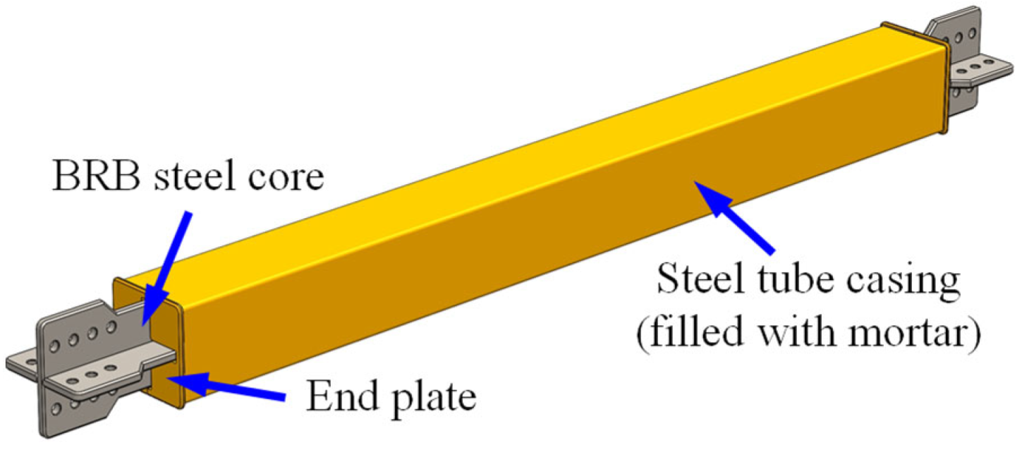
2. Working Principle and Mechanical Properties of FBRB

2.1. Working Principle of FBRB

BRB and FD are the common displacement-dependent dampers widely used in earthquake engineering. BRB is usually endowed with large-tonnage load bearing capacity and extensive energy-dissipation ability. However, conventional BRBs inevitably increase the structure lateral stiffness before yielding of the steel core, resulting in the increased seismic forces in beams and columns. It is neither efficient nor cost-effective to reduce the elastic-drift response of the structure with the use of conventional BRBs. Different from BRB, FD starts to absorb energy as long as the slippage occurs between the friction plates, while the force output of FD is far smaller than that of BRB. In view of this point, FBRB is proposed through making full use of the respective advantages of BRB and FD. The simplified hysteretic models for BRB, FD, and FBRB are illustrated in Figure 2. Note that the behaviors of BRB and FD are simplified herein using the bilinear-hardening model, but generally the slide displacement of FD is much smaller than the yield displacement of BRB. The force-deformation relationship of FBRB can be reasonably approximated as the superposition of BRB and FD, as shown in the black curve in Figure 2. Thus, the advantages of FBRB over the conventional BRB lie in: (1) FBRB dissipates appreciable seismic energy under mild ground motions (i.e., frequently-occurring earthquake (FOE)) by means of the FD components, which is helpful to increase the residence comfortability and reduce the seismic response of structures at elastic stage; and (2) a smaller lateral-drift response can be achieved in FBRB-equipped structures under severe ground motions (i.e., maximum considered earthquakes (MCE)) resulting from the increased energy dissipation capacity in FBRB. In short, FBRB is expected to have multi-stage energy-dissipation property, being adaptive to the ground motions of varied intensities.
To achieve the expected behavior, the construction of FBRB characterized by the arrangement of FD and BRB steel core in parallel is proposed, and the three-dimensional schematic is shown in Figure 3. In each FBRB, there are four friction dampers employed to connect the BRB steel casing with the end plates. Consequently, the force-transfer mechanism of FBRB can be described as: (1) friction dampers and the BRB steel casing are linked in series to constitute a friction element (FE); (2) the FE and the BRB steel core are connected in parallel to result in coordinating deformation and contribute to energy dissipation. The construction details will be further described in Section 3.

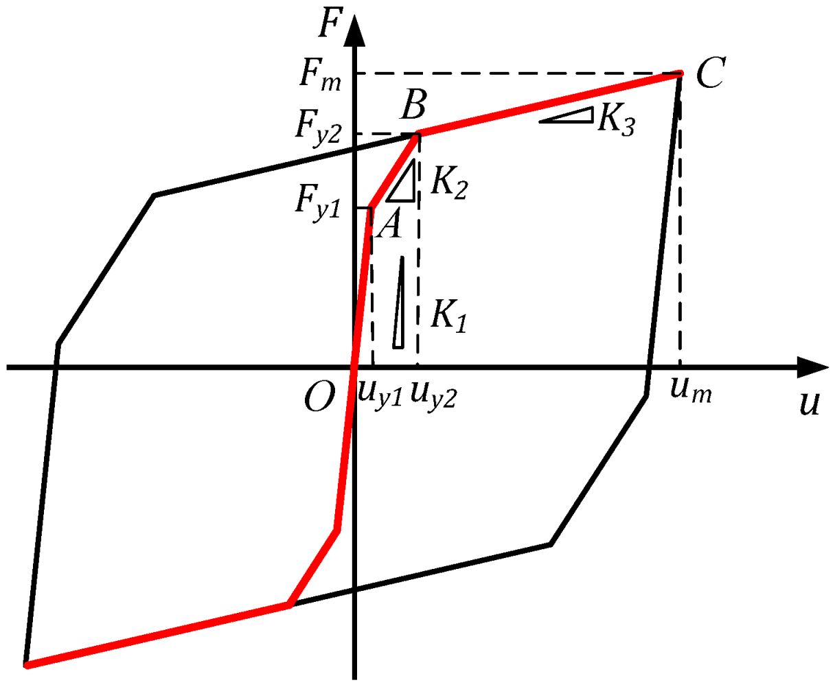
2.2. Mechanical Properties of FBRB

As shown in Figure 4, the typical monotonic force-displacement relationship of FBRB can be simplified using a tri-linear model, which is equivalent to the superposition of BRB and the FE responses. At the incipient loading stage (OA), the elongation of the FE (FD and BRB casing connected in series) results from the tensile strain in BRB casing. Considering that FE and the BRB core are in parallel connection, the axial stiffness for OA segment should satisfy:
K 1 = K f e + K b e
K f e and K b e denote the elastic stiffness of the FE and BRB steel core, respectively. K f e is provided by the elastic axial stiffness of BRB casing, i.e.,
K f e = E b c A b c / L b c
The core consists of yielding segment, transition segment, and end cruciform. Thus, K b e can be approximately estimated by considering the series connection of the three segments.
K b e = 1 L y E y A y + 2 L t r E y A t r + 2 L e c E y A e c
In Equations (2) and (3), E , A , and L represent the material-elastic modulus, cross section area and length of the device, respectively. The subscript bc denotes BRB casing, while subscripts y, tr, and ec denote the yielding segment, transition segment, and end cruciform of the BRB steel core, respectively. Point A, marking the beginning of the slide in FD, defines the stage where the maximum static friction force is reached. The FD sliding force results in tensile elongation of the BRB casing and can be calculated as
F f = K f e u y 1 = E b c A b c ε b c
while F f is the FD sliding force at point A. u y 1 and ε b c denote the slide displacement of the FE and axial-tensile strain of BRB casing at point A, respectively. The friction force in FD results from the overall bolt-pretension force P .
F f = λ μ P  
where λ is number of friction surface and μ is the friction coefficient between the friction plate and the slider. Combining Equations (2), (4) and (5), u y 1 can be determined as
u y 1 = λ μ P L b c E b c A b c
AB segment (Figure 4) corresponds to the stage where the deformation in FBRB exceeds u y 1 but is still within the yield displacement of the BRB steel core ( u y 2 ). Since the stiffness of FD can be reasonably neglected after sliding, the axial stiffness for AB segment is merely provided by the BRB, i.e.,
K 2 = K b e
At BC segment, the stiffness of FBRB is approximately equal to the post-yielding stiffness of the BRB steel core, and can be estimated by introducing the post-yield slope α B R B as.
K 2 = K b e
In the design of FBRB, the force and deformation need to be estimated when the target lateral drift of the structure is reached. The placement of BRB steel core and the FE in parallel connection results in the force relationship as
F F B R B = F B R B + F F E
where F B R B , F F E , and F F B R B are the design forces for the BRB steel core, FE, and FBRB at target displacement, and can be calculated using the tri-linear model (Figure 4). Considering that the BRB casing no longer elongates after slipping of FD, the deformation relationship between FD and BRB core should satisfy
u B R B = u y 1 + 2 u F D
where u B R B and u F D represent the deformations of BRB steel core and FD at the target displacement, respectively. Note that Equation (1) is still applicable to determine FBRB axial stiffness at a large deformation stage by replacing K f e and K b e with the effective stiffnesses using the equivalent linearization method. For instance, the average stiffness and energy (ASE) method proposed by Gates [46] can be employed to calculate the effective stiffness K e q ,
K e q = 1 u d 0 u d k s e ( u ) d u
where u d is the target deformation of FBRB and k s e ( u ) represents the secant stiffness of BRB steel core or the FE at deformation u . For a bilinear-hysteretic system, Equation (11) can be further simplified as [46]
K e q = K 0 [ 1 α μ ( 1 + l n μ ) + α ]       ( μ > 1 )
where K 0 is the elastic stiffness ( K 0 = K f e for the FE or K 0 = K b e for BRB steel core), μ is the displacement-ductility ratio ( μ = u d / u y 1 for the FE or μ = u d / u y 2 for BRB steel core), and α is the post-yield slope. Further, for the FBRB at nonlinear stage (BRB steel core and FE have yielded), its contribution to the structural-lateral stiffness can be estimated as
K l a t e r a l = i = 1 n K F B R B , i c o s 2 θ i
where K l a t e r a l is the equivalent lateral stiffness resulting from FBRB, c o s θ i is the inclination angel of the i t h FBRB, and K F B R B , i denotes the effective axial stiffness of the i t h FBRB which can be calculated by referring to Equation (12) (sum of the effective stiffnesses of the FE and BRB steel core). Additionally, the energy dissipated by the FE or BRB steel core in a cycle can be evaluated as [47]
W c = 4 F y u y ( 1 α ) ( 1 1 μ )
where F y and u y are the yield force and yield displacement, respectively. α and μ possess the same physical meaning as those in Equation (12).

3. Experimental Validation for the Proposed FBRB Construction

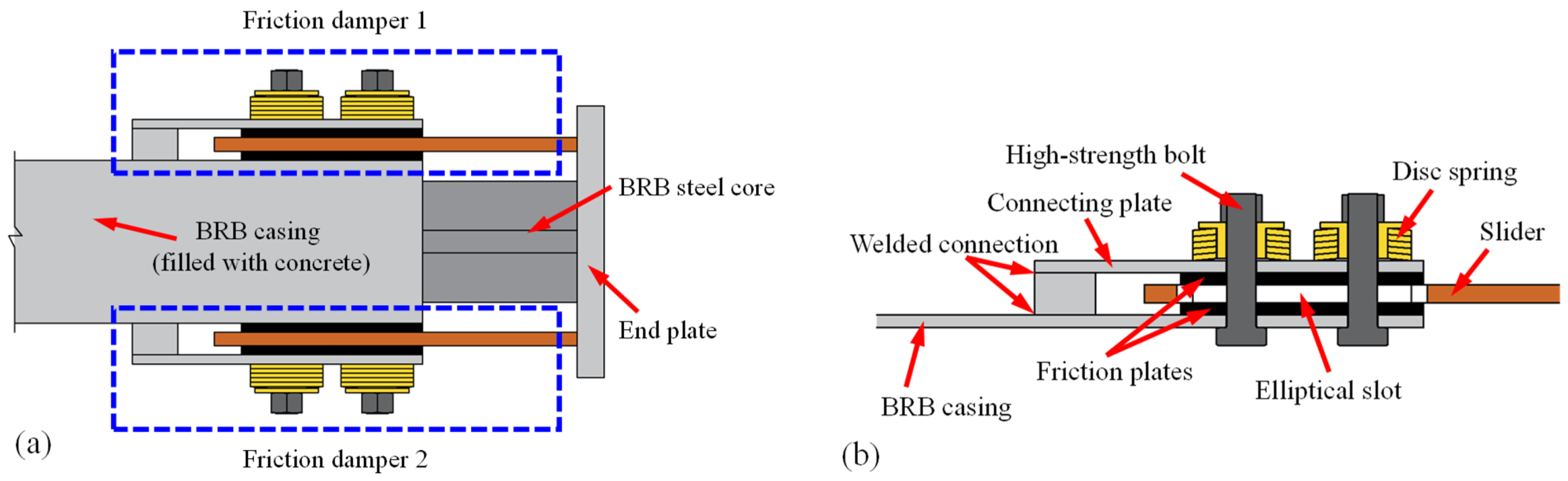
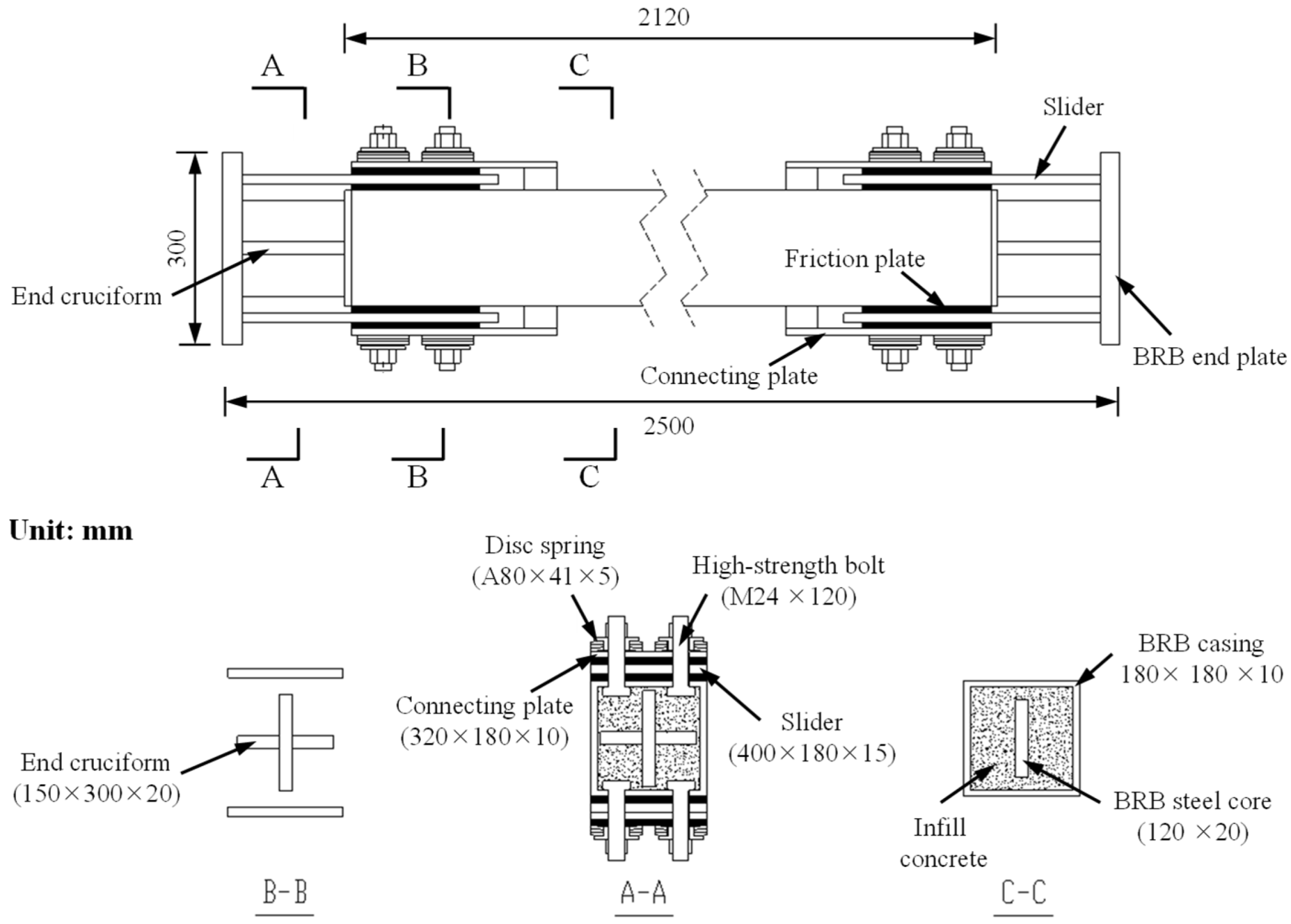
3.1. Construction Details of the FBRB Specimen

The assembly of FBRB specimen, including the construction details of the FD, is illustrated in Figure 5. The FDs are mounted on both sides of the square-steel-tube casing, as shown in Figure 5a. FD comprises of the connecting plate, friction plates, slider, high-strength bolt, and disc spring, as depicted in Figure 5b. The friction plate and slider are made of polymer composites and stainless steel, respectively. There is one friction plate directly fixed to the BRB casing, while the other one is connected to the BRB casing via the connecting plate and welded connections. The slider is welded to the BRB-end plate in such a way that FD together with the BRB square-steel-tube casing constitutes a series system. High-strength bolts and disc springs are utilized to provide the pre-tightening force in the FD. There are elliptical slots left on the slider to result in enough slide space for the slider relative to the bolts. Further, the BRB casing is filled with concrete. To guarantee the free axial deformation in the BRB steel core, a layer of thin rubber plate can be employed to segregate the BRB steel core from the surrounding concrete.

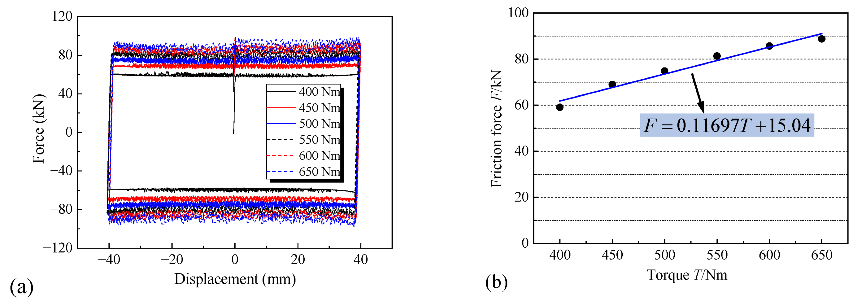
3.2. Measurement of the Friction Coefficient

The friction coefficient μ between the friction plate (polymer composites) and the slider (stainless steel) was acquired through the test. The specimen was designed as shown in Figure 6a, being similar to the friction damper shown in Figure 5b. The specimen was cyclically loaded on a 30 kN servo-controlled dynamic-testing machine, as shown in Figure 6b. The friction force was measured during the test while considering the change of torque exerted on the bolts from 400 Nm to 650 Nm. Detailed information of the test is summarized in Table 1.
The measured hysteresis curves of the specimen are shown in Figure 7a. It can be seen that the friction force increases with the increment of the torque. The friction forces observed are basically stable during the test. After smoothing the test curves and performing the regression analysis, a linear relationship between the friction force and torque can be expected, as illustrated in Figure 7b,
F = 0.11697 T + 15.04
where F and T denote the friction force and exerted torque, respectively.
T = k P c d
Further, the torque exerted on the bolts can be calculated according to Equation (16) [48], where T is the exerted torque on the bolts and k is the average torque coefficient (ranges from 0.11 to 0.15). d and P c represents the nominal diameter and pre-tightening force of the bolt, respectively. The relationship between F and P c can be established by combining Equations (15) and (16). Results indicated that μ ranged from 0.1~0.13, and a mean value of μ = 0.12 was adopted for the subsequent FBRB design.

3.3. Design of the FBRB Specimens

The reversed-cyclic test of FBRB was conducted which includes one FBRB specimen and one FE specimen. Note that the FE specimen consists of the FDs and BRB casing in a series connection (parameters of the FDs and BRB casing for FE specimen are the same as those for the FBRB specimen). Also note that the purposes of the test are to validate the proposed construction and preliminarily indicate the force-deformation relationship of FBRB, and the experimental demonstration of the advantage of FBRB over that of conventional BRB is beyond the scope of this study. The construction of the FBRB specimen, including the cutaway view, is illustrated in Figure 8. The FBRB specimen adopts the straight-shape steel core with end cruciforms and square-steel tubes as the restraining casing. The material for the BRB (yielding core and casing) and the connecting plates in FD is Q235B, while the material for the slider in FD is stainless steel. The square-steel-tube casing was infilled with C30 concrete. The geometric parameters of the FBRB specimen are listed in Table 2.
The design of the FBRB specimen follows the mechanical principles as introduced in Section 2.2. A new parameter of yield displacement ratio is defined as the ratio of BRB yield displacement to the FE slide displacement, i.e., R y d = u y 2 / u y 1 (Figure 4). The relative larger R y d will advance the energy dissipation in FD and postpone the yield of BRB steel core but, meanwhile, it improves the axial-stiffness demand of BRB casing. In design of FBRB, parameters u y 2 and R y d are usually preselected to determine u y 1 . It is desirable to establish the relationship between K f e and K b e so that there is only one independent variable to be considered during the design. Introduce the energy-dissipation ratio as the ratio of energy dissipated by the BRB core ( W B R B ) to that by the FE ( W F E ) at the maximum lateral drift, i.e., R e d = W B R B / W F E , the correlation between K f e and K b e can be built with the use of R y d , R e d , and Equation (14). After determining the BRB geometric dimension, the sliding force and bolt-pretension force for FD can be calculated according to Equation (6).
The primary performance parameters for the FBRB specimen are listed in Table 3. The design of the high-strength bolt was performed by referring to the code provisions [48]. The M24 (Grade 12.9) high-strength bolts were selected to apply the normal pretension force in FD. There were eight bolts on each side of the specimen (four bolts in each FD, as shown in Figure 3), resulting in the friction force demand of 40 kN for each bolt. The design of the disc springs complied with the rules in the code [49], and the type A disc spring of ∅80 × ∅41 × 5 × 6.7 was finally utilized in the test. Also note that the overall stabilities of the slider and connecting plate, as well as the welding strength, should be checked during the design. Furthermore, the FE specimen was designed to have the same geometric and mechanical properties as the FBRB specimen, except for the removal of the BRB steel core. In other words, the FE specimen was designed to investigate the reliability of the steel-tube-FD series system.

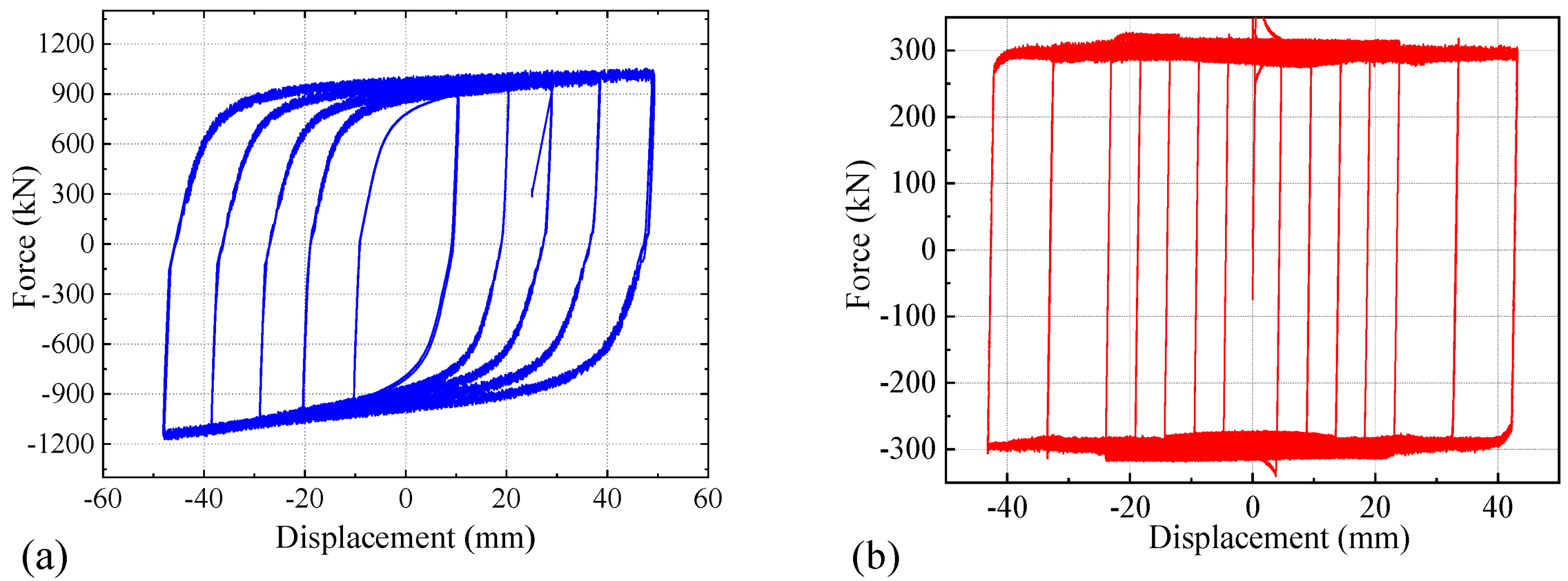
3.4. Reversed Cyclic Test of the Specimens

The specimens were loaded with a 1500 kN servo-controlled hydraulic actuator. As shown in Figure 9a, the end plates were bolted to the actuator and the counterforce frame, respectively. Displacement-controlled loading mechanism was adopted during the test. The loading protocols for the FBRB and FE specimens were illustrated in Figure 9b and Figure 9c, respectively. Three cycles were repeated at each displacement magnitude. The maximum-loading displacement was 48 mm which corresponds to the maximum 3% axial strain in the BRB steel core. The loading force was recorded by the force transducer at the end of the actuator, and the specimen displacement was recorded by the displacement sensors mounted on the BRB end plate next to the actuator. Note that there was a small amount of discrepancies between the loading protocols for the specimens without introducing any difficulty in the subsequent analysis on the hysteretic behaviors.
The sound resulting from the sliding between the friction plates and slider can be clearly heard during the experiment. The hysteresis curve for the FBRB specimen is illustrated in Figure 10a. It is noted that the observed peak load of 1183 kN is close to the design value. The hysteretic curve is basically symmetrical, with the peak-compressive force slightly larger than the peak-tensile force. This phenomenon can be attributed to the infill of concrete in the casing that provides sufficient constraint to the yielding core and restrains the local buckling of the core at a large deformation stage. The plump curve indicated steady load-bearing capacity and large energy-dissipation capacity for the specimen, without observable strength or stiffness degradations during the test. Besides, it is evident that the curve experiences stiffness mutation twice during the unidirectional loading process, indicating the point of FD sliding and BRB yielding, respectively.
The hysteretic response of the FE specimen is shown in Figure 10b. Note that the FE specimen consists of the BRB steel-tube casing and FDs in series connection. In other words, the illustration in Figure 10b is equivalent to the extraction of the contribution of the BRB core from Figure 10a. The measured peak force in the FE is close to the design value of 320 kN. It can be seen from Figure 10 that the force output in FE accounts for approximately 25% of the total force in FBRB, which is in accordance with the design objective. The hysteresis curve exhibits rectangle profile without strength degradation, indicating steady load resistance and considerable energy dissipation through the friction mechanism. The experimental results preliminarily verified that: (1) the connection between BRB and friction dampers was reliable; and (2) the proposed FBRB construction was feasible to result in steady and plump hysteretic behavior, indicating the potential application prospect of FBRB in practical engineering. The hysteretic and fatigue performances of FBRB, compared with the conventional BRB, will be further extensively evaluated in the subsequent research, both experimentally and numerically.

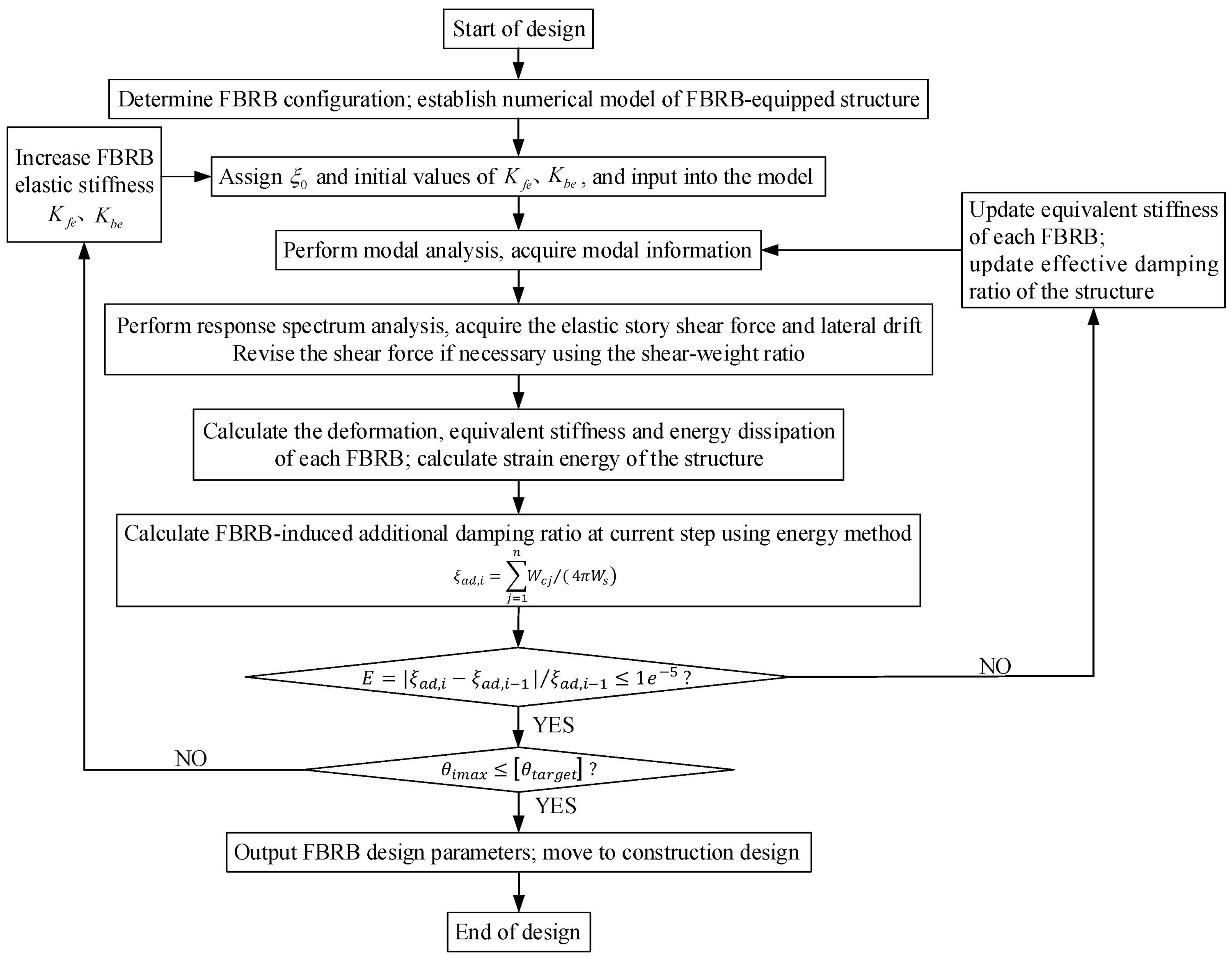
4. Parametric Design Procedures for FBRB-Equipped High-Rise Braced Frame

This section developed the parametric-design procedures to determine the FBRB mechanical parameters so that the maximum elastic-lateral drift of the FBRB-equipped frame can be reduced to the allowable value. The essence of the methodology is to calculate the elastic drift of the structure by employing response-spectrum analysis. Although the structure remains elastic under FOE, the sliding of FDs in FBRB results in the change of lateral stiffness and damping ratio of the structure. Conversely, the deformation of FBRB will be influenced by the lateral drift. Consequently, iteration is required to update the structural-lateral stiffness and equivalent damping ratio until the analysis is converged. The approach starts with assigning small values of FBRB stiffness ( K f e , K b e ) and calculating the structure-lateral drift iteratively. The iterations converge when the relative error of the FBRB-induced additional damping ratio between two adjacent iterations is within the prescribed limit. The process will be repeated until K f e and K b e are adequate to reduce the maximum elastic drift of the system to the code-specified value. The step-by-step parametric-design procedures are introduced hereinbelow.
Step 1. Predetermine the following items: (1) code-specified inter-story drift limit under FOE (as the design objective); and (2) vibration-reduction scheme, i.e., the configuration of FBRB, including the quantity, position, and the way of installation. The elastic-numerical model of the structure to be analyzed.
Step 2. Assign the intrinsic-viscous-damping ratio ξ 0 for the structure ( ξ 0 = 0.03 and ξ 0 = 0.05 are usually adopted in design of steel and RC structures, respectively). Assign the initial small values for K f e and K b e , and calculate FBRB stiffness according to Equation (1). The relationship between K f e and K b e can be established by referring to Section 3.3. Input these parameters into the numerical model.
Step 3. Perform modal analysis on the updated numerical modal. The modal information of the structure can be obtained including periods and modes of vibration.
Step 4. Perform the response-spectrum analysis. Calculate the elastic-story-shear force and lateral drift of the structure using the mode-superposition method. For high-rise buildings with long periods, the story-shear force should be revised by the coefficient of shear-weight ratio if less than the code-prescribed minimum value [50]
V E K i > λ j = i n G j
where, V E K i is the shear force for the i   th story. λ is the coefficient of shear-weight ratio and G j denotes the representative value of gravity load. Note that the number of modes included in the analysis should render the sum of corresponding modal-participation mass to be larger than 90% of the total mass, as the code prescribed [50].
Step 5. Extract the deformation of each FBRB element. For those whose deformation exceeds the slide displacement, calculate the effective stiffness using Equation (12). Calculate the energy dissipated by each FBRB element ( W c j ) according to Equation (14). Calculate the total-elastic-strain energy of the structure ( W s ) .
Step 6. Calculate the FBRB-induced additional damping ratio at the current step using the energy method, as shown in Equation (18) [50].
ξ a d , i = j = 1 n W c j / ( 4 π W s )
Step 7. Calculate the effective viscous-damping ratio of the system at the current step as ξ e , i = ξ 0 + ξ a d , i . Compare the relative error of the effective viscous-damping ratio between the two adjacent iterations. If the error ( E = | ξ a d , i ξ a d , i 1 | / ξ a d , i 1 ) is within the prescribed limit, move on to the next step; otherwise, update the equivalent stiffness of FBRB and effective damping ratio of the structure using the values yielded from the current iteration. Repeat from Step 3 to Step 7 until the requirement is satisfied.
Step 8. Judge whether the maximum inter-story drift ratio at the current step is within the code-prescribed permissive limit. If so, output the design parameters, move on to the construction design of FBRB and terminate the design procedures; otherwise, update parameters K f e and K b e and repeat Step 2 to Step 8 until the requirement is satisfied.
Figure 11 summarized the above-mentioned steps in a flow chart. It should be pointed out that the approach focuses on the elastic-drift response of the structure, and is only suitable for the preliminary design of FBRB. Further effort is required to examine the structure-nonlinear-seismic response by carrying out time-history analysis and necessarily revising the design parameters in case of any unconservative design.

5. Evaluation on the Seismic Performance of FBRB-Equipped Braced Frame

This section evaluates the proposed energy dissipation and vibration-reduction scheme by applying the FBRB to a high-rise mega-frame structure. The intent of the analysis is to validate FBRB and indicate the performance discrepancy between FBRB and conventional BRB through a case study. The approach presented in Section 4 was applied to determine the FBRB parameters in the case study. Note that the braced-frame system equipped with FBRB and conventional BRB are denoted as FBRB-BF and BRB-BF, respectively. Since the objective is to reveal the advantage of FBRB over the conventional BRB, the mechanical performance of FBRB is identical to that of the conventional BRB, except for the introduction of friction dampers. The seismic behaviors of the two sample structures were compared and critically evaluated based on the results of nonlinear time-history analyses.

5.1. The 48-Story FBRB-BF Earthquake Resisting System: Case Study

5.1.1. Information of the Structure for Case Study

The 48-story steel mega-braced frame was originally designed by Kang [51] according to the Chinese-seismic-design code [50]. The structure has a store height of 4 m, resulting in the overall height of 192 m. There are five bays in each direction with an identical column spacing of 8 m. The seismic design of the structure was carried out by considering the FOE of Intensity 8 (0.2 g) with Class Ⅱ site and Design Earthquake Group 1. To strengthen the torsional stiffness of the system, conventional BRBs were adopted to form four mega columns at the corner and three mega girders (located at 19-20 stories, 36-37 stories, and 48 story, respectively). Detailed structural-design information can be found by referring to the document [51,52].
The FBRB-BF analyzed in the case study can be acquired by replacing the BRBs in the abovementioned structure with the FBRBs, and the parameters of FBRB will be determined to satisfy the structural-seismic demands. The plane layout and elevation of the FBRB-BF are shown in Figure 12. Subsequently, the BRB-BF researched in the case study can be generated by removing all the friction dampers in the FBRBs while keeping the other parameters unchanged.

5.1.2. Parametric Design of FBRB for the Sample Structure

This section focuses on the determination of FBRB parameters so that the maximum drift response of the FBRB-BF structure under FOE can be reduced to the code-allowable value. For the FBRB-equipped structures subjected to FOE, it is required that the FE dissipates seismic energy and provides additional damping ratio, while the BRB steel core remains elastic. In view of this, the design target drift ratio is set as 1/500, while the BRB is designed to yield at a drift ratio of 1/350, assuming that the post-yield slopes for the BRB steel core and FE are 0.02 and 0, respectively. Also, the effective damping ratio of 0.03 was used in the response-spectrum analysis which was reasonable for the steel structures.
To ensure early energy dissipation of FD, the yield-displacement ratio R y d = 6 was adopted in the design. Also, R e d = 2 was adopted at a maximum lateral drift of 2% for the case structure (Section 3.3). The parametric procedure shown in Figure 11 can be implemented programmatically. After running the analysis, convergence was quickly achieved and the yielded FBRB mechanical parameters were shown in Table 4. It is evident that the FBRB provides approximately 8% of the additional viscous damping under FOE, which is believed to be efficient to reduce the displacement response of the structure. More information will be discussed in Section 5.3. The straight-shape steel and square steel tube are adopted as the BRB core and casing, respectively. The construction details of FBRB is further provided according to mechanical parameters, as shown in Table 5.

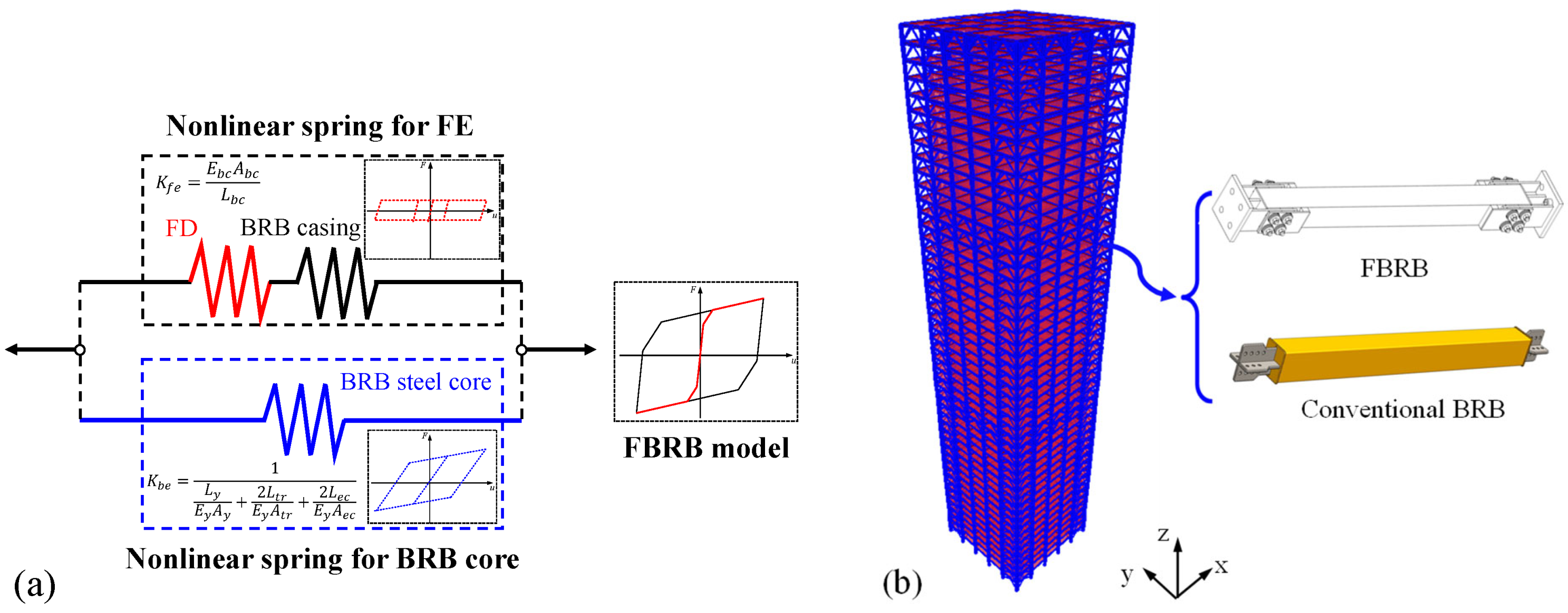
5.2. Numerical Modeling of the 48-Story FBRB-BF Structure

This section introduces the numerical modeling of the sample structures. The numerical model was developed on the OpenSees platform [53]. The simplified numerical model of FBRB is illustrated in Figure 13a. As introduced previously, FBRB consists of the FE and BRB steel core in parallel connection, and the FE is fabricated by connecting the FDs and BRB casing in series. In the analytical model, both the friction element and BRB steel core were idealized using the nonlinear spring characterized by the bilinear-hardening attribute. The truss element and Steel01 material were applied to realize this function, and the design results in Table 4 were input to quantify the model parameters. Subsequently, the two truss elements were arranged in parallel by setting up common nodes. The steel beams and columns were modeled using the displacement-based fiber element (dispBeamColumn) with five Gauss-Lobatto integration points along the element. Each beam or column was divided into three elements to improve the modeling accuracy (approximate a linear distribution of curvature along the member). Steel02 material was utilized to define the fiber section. Besides, the rigid diaphragm assumption was adopted in developing the structural model to reduce computational costs. The three-dimensional nonlinear-finite-element model for FBRB-BF and BRB-BF is shown in Figure 13b. Note that the BRB-BF model was acquired by replacing the FBRBs in the FBRB-BF model with the conventional BRBs while keeping the BRB mechanical parameters identical.
The first two order of natural periods for the two models are summarized in Table 6. The periods for x and y direction are similar because of the symmetrical plane layout. It can be seen that the periods for FBRB-BF are smaller than those for BRB-BF, resulting from the stiffness contribution of the friction dampers.

5.3. Evaluations on the Seismic Responses of FBRB-BF and BRB-BF

Nonlinear time-history analyses were carried out to evaluate the vibration-reduction effect of FBRB and figure out the response discrepancy between FBRB-BF and BRB-BF. Unidirectional-seismic excitations were applied along the x axis of the structure (Figure 13b) during the analyses. The ground-motion set, including four waves (termed El Centrol (1940), Imperial Valley-06 (1979), Loma Prieta (1989), and Artificial, respectively), was selected as the input. Information of the ground motions, including the time histories, can be found by referring to the research [30].
The elastic-acceleration spectrum of the individual ground motions considered are illustrated in Figure 14. The mean response spectrum and the code-specified design spectrum are also included in the figure. It can be seen that the mean spectrum matches reasonably well with the design spectrum. In order to assess the multi-stage energy-dissipation capacity of FBRB, the peak-ground acceleration (PGA) of the ground motions were scaled to 70 cm/s2, 400 cm/s2, and 620 cm/s2, respectively. The intensities of the scaled seismic waves correspond to FOE (with 63.2% probability of exceedance in 50 years), MCE (with 2% probability of exceedance in 50 years), and super rarely-occurring earthquakes (SRE), respectively.

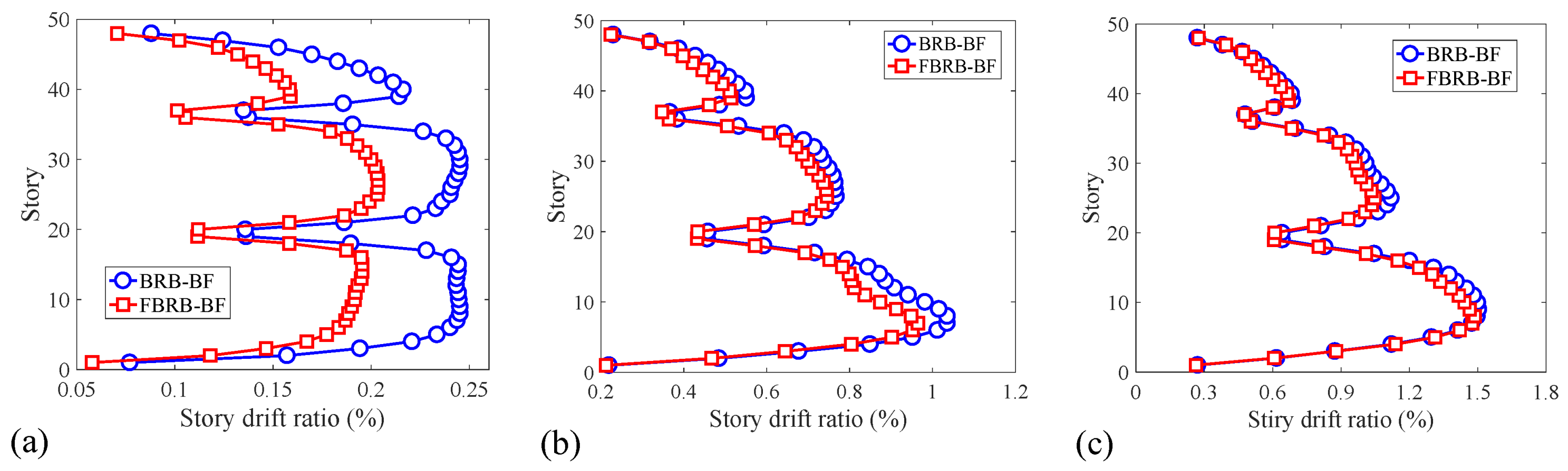
5.3.1. Lateral Drift Response

The distributions of inter-story drift ratio under different seismic intensities are shown in Figure 15. Note that the curve in each figure represents the average responses of the four ground motions. The red and blue curves in each figure denote the results of FBRB-BF and BRB-BF, respectively. It is noted that FBRB significantly reduced the inter-story drift ratio under FOE, compared with the conventional BRB, while less significant reduction effect can be observed under MCE and SRE calculation cases. Compared with BRB-BF, the average maximum inter-story drift ratio in FBRB-BF was diminished by 17.03%, 6.80%, and 1.49% under FOE, MCE, and SRE, respectively. This phenomenon is attributed to the function of FDs in FBRB. For structures subjected to FOE, the FD in FBRB dissipates considerable seismic energy and functions efficiently in weakening the structural-vibrational response through providing additional damping ratio, while the conventional BRB remains elastic and merely increases the structural-lateral stiffness, resulting in limited vibration-reduction effect.
For structures subjected to MCE or SRE, however, the BRB and structural members participate in energy absorption at a large deformation stage as well, and the vibration- reduction effect of FD is not as evident as in the FOE case. Even so, FBRB exhibits superior hysteretic performance over the conventional BRB on account of the FD. The results indicated the adaptive-passive structural control and multi-stage energy-dissipation capacities of FBRB. Besides, Figure 15a shows that the maximum drift ratio of FBRB-BF may be slightly larger than the design target, indicating that the parametric-design procedure is likely to yield unconservative results. This situation may result from the reason that the seismic-influence coefficient used in the response-spectrum method tends to underestimate the seismic forces at long periods (for high-rise buildings). Therefore, it is suggested that nonlinear-dynamic time-history analysis be included to verify the design and make modifications, if necessary.

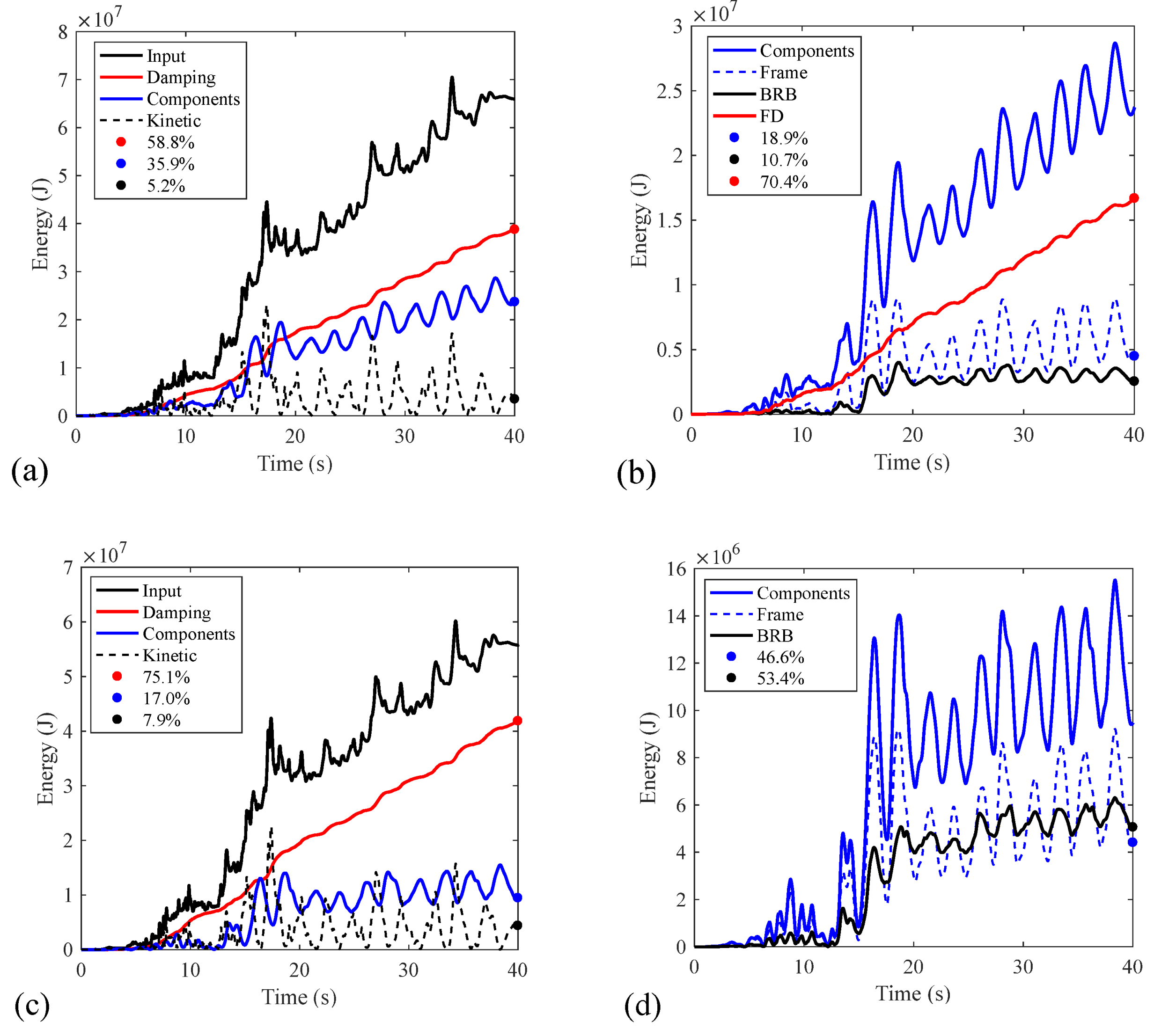
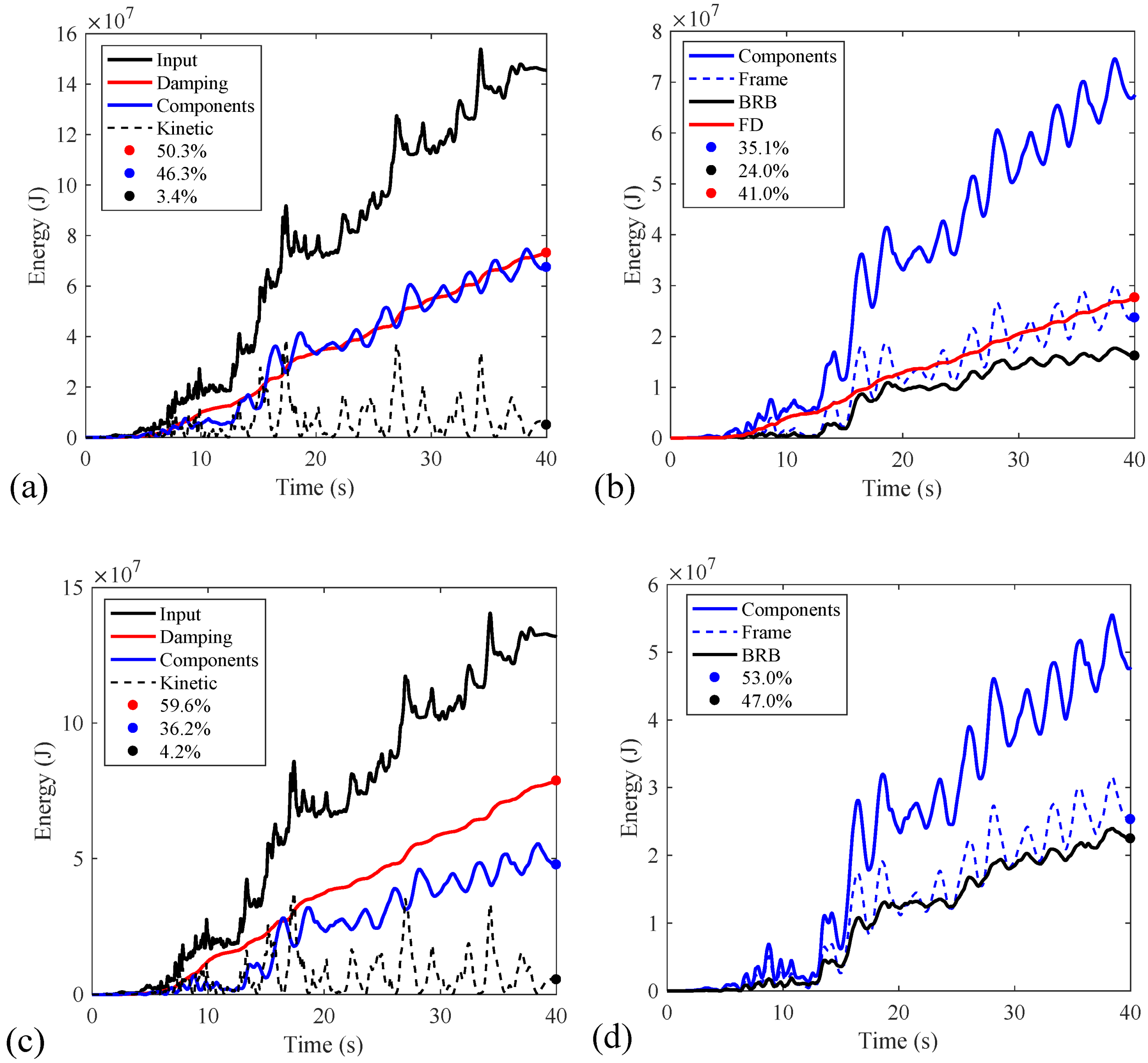
5.3.2. Seismic Energy Analysis

This section focuses on the structural responses from the energy perspective, in which energy composition and variation tendency are investigated. The responses for the Imperial Valley-06 calculation case were extracted as the example and illustrated in Figure 16, Figure 17 and Figure 18, respectively. Note that the demonstrations in Figure 16, Figure 17 and Figure 18 correspond to the seismic intensities of FOE, MCE, and SRE, respectively. In each figure, the subfigures (a) and (c) denote the energy composition for FBRB-BF and BRB-BF, respectively. It can be seen that the seismic-input energy comprises of three components: energy dissipated by the effective viscous damping of the system, energy dissipated by the structural components (beams, columns, and braces) and the kinetic energy. Subfigures (b) and (d) denote further subdivision of the energy dissipated by the structural components, i.e., the energy dissipated by the frame (beams and columns) is differentiated from that by the braces (BRB or FBRB).
For FBRB-BF or BRB-BF subjected to FOE, the majority of the input energy was absorbed by the system’s effective-viscous damping. For BRB-BF, the energy dissipated by the structural components oscillated and approached to zero, indicating that all the members remained linear-elastic. Different from BRB-BF, the energy dissipated by the structural components in FBRB-BF resulted primarily from the FD (91.8%), validating the efficiency of FBRB in vibration reduction under FOE. The energy-dissipation ratio for all the calculation cases is further summarized as shown in Figure 19. It is evident from Figure 19a that FD in FBRB dissipates 28% ~ 50% of the seismic-input energy under FOE, while the contribution of BRB core in FBRB and conventional BRB can be reasonably neglected. The above analyses verify the advantage of FBRB over the conventional BRB in terms of structural control under FOE.
The characteristics of energy composition and variation tendency under MCE and SRE calculation cases share some similarities, as shown in Figure 17 and Figure 18. There are four conclusions that can be reached through the comparative analyses: (1) The energy dissipated by the structural components in FBRB-BF accounts for larger proportion than that in BRB-BF. The reason may result from the superior energy-dissipation capacity of FBRB; (2) with the increase of seismic intensity (i.e., from MCE to SRE), the percentage of energy dissipated by the structural components increases, and the ratio of energy dissipated by the effective viscous damping inevitably declines. This trend applies to FBRB-BF and BRB-BF; (3) In FBRB-BF, the FD and BRB steel core contributes to comparable energy dissipation. However, the ratio of energy dissipated by the BRB steel core increases with the increase of seismic intensity, while the ratio of energy dissipated by the FD displays an opposite tendency; and (4) the ratios of the energy dissipated by the frame and BRB in FBRB-BF are smaller than those by the frame and BRB in BRB-BF, respectively. This conclusion can also be inferred from comparing Figure 19b,c that the red lines are below the black ones. The phenomenon indicates the significance of FD in energy dissipation under MCE and SRE. Also, the function of FD would to some extent reduce the nonlinear deformation in the BRB steel core, and be expected to increase the low-cycle-fatigue performance of FBRB. Based on the above discussions, the performance advantage of FBRB over the conventional BRB under MEC and SRE can be soundly supported.

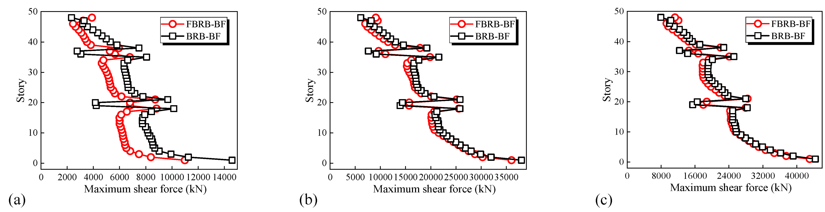
5.3.3. Distributions of Inter-Story Shear Forces

The distributions of story shear forces for FBRB-BF and BRB-BF under different earthquake intensities are depicted in Figure 20. Note that the values in each subfigure represent the averaged response of the four ground motions. Similar characteristics can be observed among these subfigures. There exists an abrupt change of the story-shear force near the mega girders over the height of the structure, which results from the mutation of lateral stiffness at the stories of mega girders. Besides, the story-shear forces in FBRB-BF are generally smaller than those in BRB-BF, and the phenomenon is especially evident under the FOE case. The situation may be attributed to the effect of FDs in FBRB. The FD participates in energy consumption throughout the earthquake action, resulting in the increased system-viscous damping and reduced deformation demands in the BRB steel core, and the story-shear forces can be correspondingly lowered.
The limitations of this study lie in the following aspects: (1) There lacks enough FBRB specimens in the experimental investigation. The advantages of FBRB over the conventional BRB cannot be soundly supported by the test results; (2) Iterations are required to determine the FBRB equivalent stiffness and viscous damping in the parametric-design method. It would be time-consuming to calculate the structure-modal parameters. The approach based on the response-spectrum analysis is likely to estimate the seismic forces for structures with long periods; (3) The numerical model of FBRB needs to be further verified with abundant test data; and (4) The performance verification of FBRB-BF and BRB-BF needs to be validated against acceptance criteria as prescribed in the standard [54]. Also note that the measure and guarantee of the friction force in FBRB are generally not easy to realize, which may weaken the cost-effectiveness of the friction dampers, compared to the viscoelastic ones. Subsequent studies will be carried out to address the abovementioned issues. The second-stage test will be conducted to investigate the hysteretic performance and low-cycle fatigue behavior of FBRB. With the use of test data, the numerical model of FBRB considering the fatigue behavior will be developed and verified. Further, the design of FBRB-equipped system will be extended by focusing on the structural-inelastic responses using the seismic-energy-balance principle.

6. Conclusions

This study proposes the frictional-yielding compounded BRB characterized by the adaptive passive-control capacity and the corresponding braced-frame-earthquake-resisting system with the use of FBRB. FBRB can be fabricated by connecting the BRB square- tube casing and end plates with the friction dampers so that the BRB steel core and FDs will undergo compatible deformation. FBRB is expected to not only increase the structural- lateral stiffness but also remarkably improves the system-viscous damping without yielding the BRB core under FOE. On the other hand, FBRB will exhibit superior energy- dissipation capacity than the conventional BRB under severe ground motions owing to the function of FD, presenting the adaptive passive-control and multi-stage energy-dissipation abilities. The working principle and mechanical properties of FBRB were introduced at first. Quasi-static reversed-cyclic test of one FBRB specimen and one FD specimen was conducted to validate the FBRB cyclic performance. Subsequently, a parametric- design procedure was developed to acquire the FBRB parameters so that the maximum elastic-drift ratio of FBRB-equipped braced frame can be diminished to the code-prescribed value. A case study that includes two 48-story models (FBRB-BF and BRB-BF) was carried out and the seismic performances of the structures were critically evaluated through comparative analysis. According to the research in this work, the primary conclusions can be reached as follows:
(1)
The FBRB device, characterized by the multi-stage passive control and energy dissipation, was proposed. The quasi-static test revealed that a maximum of 3% axial strain in the BRB steel core and a peak load of 1183 kN were achieved in the specimen, while maintaining steady and plump-hysteretic behavior. The construction details and hysteretic behavior of FBRB were experimentally validated.
(2)
A parametric-design procedure was developed which could be applied to preliminarily determine the FBRB parameters in FBRB-BF. The case study indicates that the method may yield unconservative results in some cases since the response-spectrum method is likely to underestimate the seismic forces at long periods. Dynamic time-history analysis is suggested to be supplemented, and the parameters should be modified if necessary.
(3)
FBRB significantly reduced the structural inter-story drift ratio under FOE, compared with the conventional BRB (up to 20%). The FD in FBRB dissipated 13%~42% of the seismic-input energy under FOE, validating the efficiency of FBRB in vibration reduction under FOE.
(4)
The ratio of energy dissipation for the BRB steel core in FBRB gradually rose with the increase of earthquake intensity. The FD in FBRB consumed comparable seismic energy as the BRB steel core at nonlinear stage, which is conducive to the relief of frame damage and improving the low-cycle fatigue performance of BRB steel core.
(5)
The story-shear forces in FBRB-BF were generally smaller than those in BRB-BF because of the effect of FD in FBRB. The phenomenon was especially obvious under the FOE case. FBRB exhibited preferable adaptive passive-control capability, and can be promoted in practical engineering.

Author Contributions

Conceptualization, J.O. and N.M.; methodology, X.Z. and T.S.; software, B.S.; validation, X.Z., T.S. and B.S.; formal analysis, X.Z. and T.S.; investigation, X.Z.; resources, B.S. and N.M.; data curation, X.Z.; writing—original draft preparation, X.Z. and T.S.; writing—review and editing, X.Z. and T.S.; visualization, N.M.; supervision, J.O.; project administration, J.O.; funding acquisition, J.O. All authors have read and agreed to the published version of the manuscript.

Funding

This research was funded by “National Natural Science Foundation of China, grant numbers 51921006, 52108439 and 52108133 ”, “National Key R&D Program of China, grant number 2018YFC0705603”, “Jiangsu Youth Fund Projects, grant number BK20210371”, and “Fundamental Research Funds for the Central Universities, grant number B210201019”.

Institutional Review Board Statement

Not applicable.

Informed Consent Statement

Not applicable.

Data Availability Statement

Data supporting the reported results can be found in publicly achieved datasets analyzed during the study.

Conflicts of Interest

The authors declare no conflict of interest.

References

  1. David, R.G.; Sarif, N. Seismic performance of eccentrically braced frames. In Proceedings of the 7th International Conference on Intelligent Textiles & Mass Customisation, Marrakech, Morocco, 13–15 November 2019; IOP Conference Series: Materials Science and Engineering. IOP Publishing: London, UK, 2020; p. 12021. [Google Scholar]
  2. Abou-Elfath, H.; Ramadan, M.; Alkanai, F.O. Upgrading the seismic capacity of existing RC buildings using buckling restrained braces. Alex. Eng. J. 2017, 56, 251–262. [Google Scholar] [CrossRef]
  3. Tremblay, R.; Poncet, L.; Bolduc, P.; Neville, R.; DeVall, R. Testing and design of buckling restrained braces for Canadian application. In Proceedings of the 13th World Conference on Earthquake Engineering, Vancouver, BC, Canada, 1–6 August 2004; pp. 1–6. [Google Scholar]
  4. Naghavi, M.; Rahnavard, R.; Thomas, R.J.; Malekinejad, M. Numerical evaluation of the hysteretic behavior of concentrically braced frames and buckling restrained brace frame systems. J. Build. Eng. 2019, 22, 415–428. [Google Scholar] [CrossRef]
  5. Chen, H.; Bai, J. Loading protocols for seismic performance evaluation of buckling-restrained braces in RC frames. J. Build. Eng. 2022, 45, 103522. [Google Scholar] [CrossRef]
  6. Bai, J.; Chen, H.; Zhao, J.; Liu, M.; Jin, S. Seismic design and subassemblage tests of buckling-restrained braced RC frames with shear connector gusset connections. Eng. Struct. 2021, 23, 4112018. [Google Scholar] [CrossRef]
  7. Takeuchi, T. Buckling-restrained brace: History, design and applications. In Key Engineering Materials; Trans Tech Publications Ltd.: Seestrasse, Switzerland, 2018; pp. 50–60. [Google Scholar]
  8. Almeida, A.; Ferreira, R.; Proença, J.M.; Gago, A.S. Seismic retrofit of RC building structures with Buckling Restrained Braces. Eng. Struct. 2017, 130, 14–22. [Google Scholar] [CrossRef]
  9. Castaldo, P.; Tubaldi, E.; Selvi, F.; Gioiella, L. Seismic performance of an existing RC structure retrofitted with buckling restrained braces. J. Build. Eng. 2021, 33, 101688. [Google Scholar] [CrossRef]
  10. Xie, Q. State of the art of buckling-restrained braces in Asia. J. Constr. Steel Res. 2005, 61, 727–748. [Google Scholar] [CrossRef]
  11. Wang, C.; Chen, Q.; Zeng, B.; Meng, S. A novel brace with partial buckling restraint: An experimental and numerical investigation. Eng. Struct. 2017, 150, 190–202. [Google Scholar] [CrossRef]
  12. Kimura, K.; Yoshioka, K.; Takeda, T.; Fukuya, Z.; Takemoto, K. Tests on braces encased by mortar in-filled steel tubes. In Summaries of Technical Papers of Annual Meeting; Architectural Institute of Japan: Tokyo, Japan, 1976; pp. 1041–1042. [Google Scholar]
  13. Watanabe, A.; Hitomi, Y.; Saeki, E.; Wada, A.; Fujimoto, M. Properties of brace encased in buckling-restraining concrete and steel tube. In Proceedings of the Ninth World Conference on Earthquake Engineering, Tokyo, Japan, 2–9 August 1988; pp. 719–724. [Google Scholar]
  14. Suzuki, N.; Kono, R.; Higasibata, Y.; Sasaki, T.; Segawa, T. Experimental study on the H-section steel brace encased in RC or steel tube. In Summaries of Technical Papers of Annual Meeting; Architectural Institute of Japan: Tokyo, Japan, 1994; pp. 1621–1622. [Google Scholar]
  15. Tremblay, R.; Bolduc, P.; Neville, R.; DeVall, R. Seismic testing and performance of buckling-restrained bracing systems. Can. J. Civil Eng. 2006, 33, 183–198. [Google Scholar] [CrossRef]
  16. Black, C.J.; Makris, N.; Aiken, I.D. Component testing, seismic evaluation and characterization of buckling-restrained braces. J. Struct. Eng. 2004, 130, 880–940. [Google Scholar] [CrossRef]
  17. Wang, C.; Usami, T.; Funayama, J. Evaluating the influence of stoppers on the low-cycle fatigue properties of high-performance buckling-restrained braces. Eng. Struct. 2012, 41, 167–176. [Google Scholar] [CrossRef]
  18. Takeuchi, T.; Hajjar, J.F.; Matsui, R.; Nishimoto, K.; Aiken, I.D. Local buckling restraint condition for core plates in buckling restrained braces. J. Constr. Steel. Res. 2010, 66, 139–149. [Google Scholar] [CrossRef]
  19. Takeuchi, T.; Ida, M.; Yamada, S.; Suzuki, K. Estimation of cumulative deformation capacity of buckling restrained braces. J. Struct. Eng. 2008, 134, 822–831. [Google Scholar] [CrossRef]
  20. Zona, A.; Dall’Asta, A. Elastoplastic model for steel buckling-restrained braces. J. Constr. Steel. Res. 2012, 68, 118–125. [Google Scholar] [CrossRef]
  21. Asgarian, B.; Amirhesari, N. A comparison of dynamic nonlinear behavior of ordinary and buckling restrained braced frames subjected to strong ground motion. Struct. Des. Tall Spec. Build. 2008, 17, 367–386. [Google Scholar] [CrossRef]
  22. Fahnestock, L.A.; Ricles, J.M.; Sause, R. Experimental evaluation of a large-scale buckling-restrained braced frame. J. Struct. Eng. 2007, 133, 1205–1214. [Google Scholar] [CrossRef]
  23. Mazzolani, F.M.; Corte, G.D.; D’Aniello, M. Experimental analysis of steel dissipative bracing systems for seismic upgrading. J. Civ. Eng. Manag. 2009, 15, 7–19. [Google Scholar] [CrossRef] [Green Version]
  24. Mahrenholtz, C.; Lin, P.C.; Wu, A.C.; Tsai, K.C.; Hwang, S.J.; Lin, R.Y.; Bhayusukma, M.Y. Retrofit of reinforced concrete frames with buckling-restrained braces. Earthq. Eng. Struct. Dyn. 2015, 44, 59–78. [Google Scholar] [CrossRef]
  25. Sabelli, R.; Mahin, S.; Chang, C. Seismic demands on steel braced frame buildings with buckling-restrained braces. Eng. Struct. 2003, 25, 655–666. [Google Scholar] [CrossRef]
  26. Choi, H.; Kim, J. Energy-based seismic design of buckling-restrained braced frames using hysteretic energy spectrum. Eng. Struct. 2006, 28, 304–311. [Google Scholar] [CrossRef]
  27. Maley, T.J.; Sullivan, T.J.; Corte, G.D. Development of a displacement-based design method for steel dual systems with buckling-restrained braces and moment-resisting frames. J. Earthq. Eng. 2010, 14, 106–140. [Google Scholar] [CrossRef]
  28. Sahoo, D.R.; Chao, S. Performance-based plastic design method for buckling-restrained braced frames. Eng. Struct. 2010, 32, 2950–2958. [Google Scholar] [CrossRef]
  29. Wararuksajja, W.; Leelataviwat, S.; Warnitchai, P.; Bing, L.; Tariq, H.; Naiyana, N. Seismic Strengthening of Soft-Story RC Moment Frames. In Proceedings of the 25th National Convention on Civil Engineering, Chonburi, Thailand, 15–17 July 2020; pp. STR47 1–STR47 7. [Google Scholar]
  30. Zhou, X.; Sun, T.; Sun, B.; Ma, N.; Ou, J. Vibration-Reduction Strategy for High-Rise Braced Frame Using Viscoelastic-Yielding Compounded BRB. Buildings 2022, 12, 1159. [Google Scholar] [CrossRef]
  31. Miller, D.J.; Fahnestock, L.A.; Eatherton, M.R. Development and experimental validation of a nickel–titanium shape memory alloy self-centering buckling-restrained brace. Eng. Struct. 2012, 40, 288–298. [Google Scholar] [CrossRef]
  32. Nazarimofrad, E.; Shokrgozar, A. Seismic performance of steel braced frames with self-centering buckling-restrained brace utilizing superelastic shape memory alloys. Struct. Des. Tall Spec. Build. 2019, 28, e1666. [Google Scholar] [CrossRef]
  33. Chou, C.; Tsai, W.; Chung, P. Development and validation tests of a dual-core self-centering sandwiched buckling-restrained brace (SC-SBRB) for seismic resistance. Eng. Struct. 2016, 12, 130–141. [Google Scholar] [CrossRef]
  34. Xu, L.H.; Fan, X.W.; Li, Z.X. Cyclic behavior and failure mechanism of self-centering energy dissipation braces with pre-pressed combination disc springs. Earthq. Eng. Struct. Dyn. 2017, 46, 1065–1080. [Google Scholar] [CrossRef]
  35. Pan, P.; Li, W.; Nie, X.; Deng, K.; Sun, J. Seismic performance of a reinforced concrete frame equipped with a double-stage yield buckling restrained brace. Struct. Des. Tall Spec. Build. 2017, 26, e1335. [Google Scholar] [CrossRef]
  36. Kim, D.; Lee, C.; Ju, Y.K. Experimental investigation of hybrid buckling-restrained braces. Int. J. Steel Struct. 2017, 17, 245–255. [Google Scholar] [CrossRef]
  37. Kim, D.H.; Ju, Y.K.; Kim, M.H.; Kim, S.D. Wind-induced vibration control of tall buildings using hybrid buckling-restrained braces. Struct. Des. Tall Spec. Build. 2014, 23, 549–562. [Google Scholar] [CrossRef]
  38. López-Almansa, F.; De la Cruz, S.T.; Taylor, C. Experimental study of friction dissipators for seismic protection of building structures. Earthq. Eng. Eng. Vib. 2011, 10, 475–486. [Google Scholar] [CrossRef] [Green Version]
  39. Fitzgerald, T.F.; Anagnos, T.; Goodson, M.; Zsutty, T. Slotted bolted connections in aseismic design for concentrically braced connections. Earthq. Spectra 1989, 53, 83–91. [Google Scholar] [CrossRef]
  40. Pall, A.S.; Marsh, C. Response of friction damped braced frames. J. Struct. Eng. 1982, 108, 1313–1323. [Google Scholar] [CrossRef]
  41. Nims, D.K.; Richter, P.J.; Bachman, R.E. The use of the energy dissipating restraint for seismic hazard mitigation. Earthq. Spectra 1993, 9, 467–489. [Google Scholar] [CrossRef]
  42. Filiatrault, A. Seismic Design of Friction Damped Braced Steel Plane Frames by Energy Methods; University of British Columbia: Vancouver, BC, Canada, 1988. [Google Scholar]
  43. Filiatrault, A.; Cherry, S. Seismic design spectra for friction-damped structures. J. Struct. Eng. 1990, 116, 1334–1355. [Google Scholar] [CrossRef]
  44. Mualla, I.H.; Belev, B. Performance of steel frames with a new friction damper device under earthquake excitation. Eng. Struct. 2002, 24, 365–371. [Google Scholar] [CrossRef]
  45. Franchek, M.A.; Ryan, M.W.; Bernhard, R.J. Adaptive passive vibration control. J. Sound. Vib. 1996, 189, 565–585. [Google Scholar] [CrossRef]
  46. Gates, N.C. The Earthquake Response of Deteriorating Systems; California Institute of Technology: Pasadena, CA, USA, 1977. [Google Scholar]
  47. Sun, T.; Kurama, Y.C.; Ou, J. Practical displacement-based seismic design approach for PWF structures with supplemental yielding dissipators. Eng. Struct. 2018, 172, 538–553. [Google Scholar] [CrossRef]
  48. JGJ82-2011; Technical Specification for High Strength Bolt Connections of Steel Structures. Ministry of Housing and Urban-Rural Development of the People’s Republic of China: Beijing, China, 2011.
  49. GB/T 1972-2005; Disc Spring. Standardization Administration: Beijing, China, 2005.
  50. GB50011-2010; Code for Seismic Design of Buildings. Ministry of Construction of the People’s Republic of China: Beijing, China, 2010.
  51. Kang, J. Seismic performance analysis and design of high-rise buildings with energy dissipation devices under super-strong earthquake. Dalian University of Technology: Dalian, China, 2015. (In Chinese) [Google Scholar]
  52. Sun, B.; Zhang, Y.; Dai, D.; Wang, L.; Ou, J. Seismic fragility analysis of a large-scale frame structure with local nonlinearities using an efficient reduced-order Newton-Raphson method. Soil Dyn. Earthq. Eng. 2023, 164, 107559. [Google Scholar] [CrossRef]
  53. McKenna, F.; Fenves, G.L.; Scott, M.H.; Jeremic, B. Open System for Earthquake Engineering Simulation (OpenSees); Pacific Earthquake Engineering Research Center, Univeristy of California: Berkley, CA, USA, 2013. [Google Scholar]
  54. ASCE/SEI 41-06; Seismic Rehabilitation of Existing Buildings. American Society of Civil Engineers: Reston, VA, USA, 2007.
Figure 1. Schematic of the conventional BRB.
Buildings 12 02123 g001
Figure 2. Simplified hysteretic models for BRB, FD, and FBRB.
Buildings 12 02123 g002
Figure 3. Schematic of the proposed FBRB.
Buildings 12 02123 g003
Figure 4. Force-displacement relationship of FBRB.
Buildings 12 02123 g004
Figure 5. Construction details of FBRB: (a) connections between BRB and friction damper; and (b) details of the friction damper.
Buildings 12 02123 g005
Figure 6. Material-property test: (a) schematic of the test specimen; and (b) on-site loading test.
Buildings 12 02123 g006
Figure 7. Experiment results: (a) hysteresis loop; and (b) relationship between the torque and friction force.
Buildings 12 02123 g007
Figure 8. Configuration and sectional drawing of the FBRB specimen.
Buildings 12 02123 g008
Figure 9. Reversed cyclic test and loading protocols: (a) on-site loading equipment; (b) loading protocols for FBRB specimen; and (c) loading protocols for FE specimen.
Buildings 12 02123 g009
Figure 10. Hysteretic responses for the tested specimens: (a) FBRB; and (b) the friction element (FE).
Buildings 12 02123 g010
Figure 11. Parametric design procedures for FBRB-equipped structures.
Buildings 12 02123 g011
Figure 12. Plane layout and elevation of the FBRB-BF structure: (a) plane layout; and (b) elevation.
Buildings 12 02123 g012
Figure 13. Analytical models for FBRB-BF and BRB-BF: (a) simplified analytical model for FBRB; and (b) three-dimensional finite-element models for FBRB-BF and BRB-BF.
Buildings 12 02123 g013
Figure 14. Acceleration response spectra for the ground motions.
Buildings 12 02123 g014
Figure 15. Average responses of the inter-story drift ratio: (a) under FOE; (b) under MCE; and (c) under SRE.
Buildings 12 02123 g015
Figure 16. Seismic-energy analysis (Imperial Valley-06 case, PGA = 70 cm/s2): (a) energy composition time-histories (FBRB-BF); (b) energy dissipated by the components (FBRB-BF); (c) energy composition time-histories (BRB-BF); and (d) energy dissipated by the components (BRB-BF).
Buildings 12 02123 g016
Figure 17. Seismic-energy analysis (Imperial Valley-06 case, PGA = 400 cm/s2): (a) energy composition time-histories (FBRB-BF); (b) energy dissipated by the components (FBRB-BF); (c) energy composition time-histories (BRB-BF); and (d) energy dissipated by the components (BRB-BF).
Buildings 12 02123 g017
Figure 18. Seismic-energy analysis (Imperial Valley-06 case, PGA = 620 cm/s2): (a) energy composition time-histories (FBRB-BF); (b) energy dissipated by the components (FBRB-BF); (c) energy composition time-histories (BRB-BF); and (d) energy dissipated by the components (BRB-BF).
Buildings 12 02123 g018
Figure 19. Energy-dissipation ratio of the brace: (a) PGA = 70 cm/s2; (b) PGA = 400 cm/s2; and (c) PGA = 620 cm/s2.
Buildings 12 02123 g019
Figure 20. Distributions of story-shear force: (a) PGA = 70 cm/s2; (b) PGA = 400 cm/s2; and (c) PGA = 620 cm/s2.
Buildings 12 02123 g020
Table 1. Detailed information of the material test.
No.MaterialMaximum Displacement (mm)Torque Exerted on Bolts (Nm)Repeated Cycles
FPpolymer composites40400/450/500/550/600/6503
Table 2. Geometric parameters of the FBRB specimen.
BRBFD
Overall Length
(mm)
Length of
Yield Segment (mm)
Area of
Yield Segment
(mm2)
Section of
BRB Casing
(mm)
Length of BRB Casing
(mm)
Size of
Friction Plates (mm)
Number of Friction Plates
250016002400☐180 × 180 × 10212080 × 16016
Table 3. Performance parameters of the FBRB specimen.
BRBFDFBRB Ultimate Force (kN)Yield-Displacement
Ratio (R)
Yield
Displacement
(mm)
Yield Force (kN)Ultimate Axial Strain Slide Displacement
(mm)
Sliding Force (kN)Friction Coefficient
2.55643%0.53200.1212005
Table 4. Primary mechanical parameters for FBRB.
BRBFD
Yield
Displace-Ment
(mm)
Yield Force (kN)Force at 1/500 Drift Ratio (kN)Post Yield Slope Slide Displacement
(mm)
Sliding Force (kN)Energy Dissipated at 1/500 Drift Ratio (kNm)Additional Damping Ratio
8.11267.5887.250.021.35261352.827.99%
Table 5. Construction details of the FBRB.
BRBFD
Overall Length
(mm)
Length of
Yield Segment (mm)
Area of
Yield Segment
(mm2)
Section of
BRB Casing
(mm)
Length of BRB Casing
(mm)
Size of
Friction Plates (mm)
Number of Friction Plates
565747304436☐220 × 220 × 8 × 84817120 × 20016
Table 6. Periods information for FBRB-BF and BRB-BF.
1st Order (x)1st Order (y)1st Order (Torsional)2nd Order (x)2nd Order (y)2nd Order (Torsional)
FBRB-BF5.515.51.731.720.890.88
BRB-BF6.076.051.961.951.031.02
Publisher’s Note: MDPI stays neutral with regard to jurisdictional claims in published maps and institutional affiliations.

