Article

Using a Biomimicry Approach in the Design of a Kinetic Façade to Regulate the Amount of Daylight Entering a Working Space

1
Japan Advanced Institute of Science and Technology, Nomi 923-1211, Ishikawa, Japan
2
School of Information, Computer and Communication Technology, Sirindhorn International Institute of Technology, Thammasat University, Pathumthani 12120, Thailand
3
National Electronics and Computer Technology Centre (NECTEC), Pathumthani 12120, Thailand
4
Faculty of Architecture and Planning, Thammasat University, Pathumthani 12120, Thailand
*
Authors to whom correspondence should be addressed.
Buildings 2022, 12(12), 2089; https://doi.org/10.3390/buildings12122089
Submission received: 14 October 2022 / Revised: 19 November 2022 / Accepted: 22 November 2022 / Published: 29 November 2022
(This article belongs to the Special Issue Metrology for Living Environment)

Abstract

:
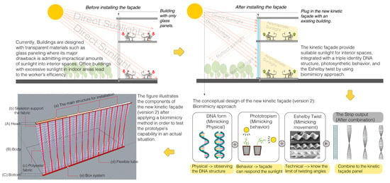
At present, buildings are increasingly being designed with transparent materials, with glass paneling being especially popular as an installation material due to its architectural allure. However, its major drawback is admitting impractical amounts of sunlight into interior spaces. Office buildings with excessive sunlight in indoor areas lead to worker inefficiency. This article studied kinetic façades as means to provide suitable sunlight for interior spaces, integrated with a triple-identity DNA structure, photosynthetic behavior, and the twist, which was divided into generation and evaluation. The generating phase first used an evolutionary engine to produce potential strip patterns. The kinetic façade was subsequently evaluated using the Climate Studio software to validate daylight admission in an indoor space with Leadership in Energy and Environmental Design (LEED) version 4.1 criteria. To analyze the kinetic façade system, the building envelope was divided into four types: glass panel, static façade, rotating façade (the kinetic façade, version 1); an existing kinetic façade that is commonly seen in the market, and twisting façade (the kinetic façade, version 2); the kinetic façade that uses the process to invent the new identity of the façade. In addition, for both the rotating façade and twisting façade, the degrees of simulation were 20, 50, 80, and 100 degrees, in order to ascertain the potential for both façades to the same degree. Comparing all façades receiving the daylight factor (DF) into the space with more or less sunlight resulted in a decreasing order of potential, as follows: entirely glass façade, twisting façade (the kinetic façade, version 2), rotating façade (the kinetic façade, version 1), and static façade. By receiving the daylight factor (DF), the façade moderately and beneficially filtered appropriate amounts of daylight into the working space. The daylight simulation results indicated that the newly designed kinetic façade (version 2) had more potential than other building envelope types in terms of filtering beneficial daylight in indoor areas. This article also experimented with the kinetic façade prototype in an actual situation to test conditional environmental potential. The twisting façade (the kinetic façade, version 2) was explored in the building envelope with varied adaptability to provide sunlight and for private-to-public, public-to-private, or semi-public working areas.

Graphical Abstract

1. Introduction

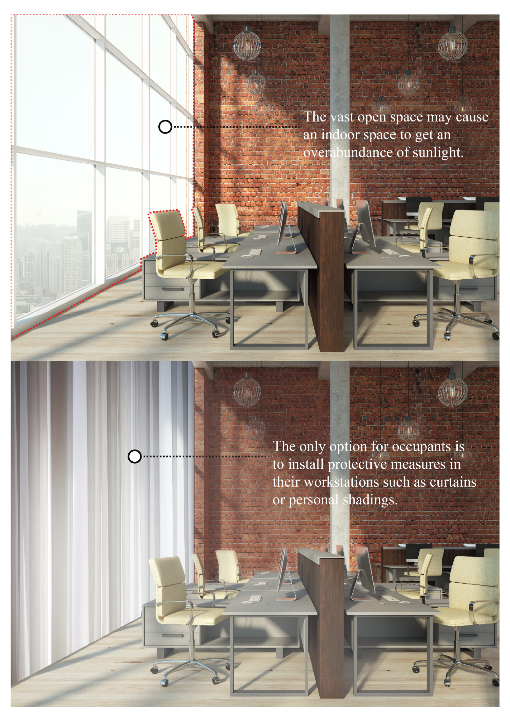
Currently, buildings are created with oversized proportions of transparent materials or vast open areas within the building envelope [1,2] since this can be used to treat the buildings and is fascinating in terms of aesthetics. However, having more windows, open spaces, and transparent elements is also disadvantageous, particularly in terms of user performance, energy efficiency, etc. An example of a building that was designed with an exaggerated proportion of transparent materials or a massive amount of open building envelope space is the Suvarnabhumi International Airport, Thailand, as shown in Figure 1, which has a problem with receiving excessive sunlight in the interior space. Thus, it adversely affects users, who view it as uncomfortable and a waste of space [2,3,4]. Furthermore, in the case of working spaces, it is common for users to be uncomfortable using the area, since they receive excessive sunlight [5], as shown in Figure 2. This directly affects individuals who actively use these spaces [6], especially in terms of physical wellness. In this case, the primary solution is that most occupants solve this problem by using a curtain or personal shading equipment, which is hung to the window. Initially, this can help with sun protection; however, it is not practical to use these devices long-term, since they cannot filter suitable natural light. Natural light affects human health, particularly eyestrain, which is a common condition that occurs when eyes become exhausted from prolonged use, such as staring at computer displays or other digital devices, reading, or working in front of a computer [7,8]. Almost all eye discomfort is caused by insufficient illumination and excessive illumination, both natural light and artificial light [9].
In this study, we considered the building occupants’ performance of various tasks. For example, during working hours, it is vital that the amount of natural light is neither excessive nor insufficient. Thus, the filtration façade between the exterior and interior is crucial. We studied the façade innovation by looking at existing façades on the market that still do not meet the needs of building users. For example, batten façades or static façades are highly popular decorations for the exterior of buildings with an excessive amount of open space or windows, since they can help prevent direct sunlight. They also contribute to the building’s aesthetic appeal when installed. However, they have some drawbacks, particularly the admission of inadequate natural light into the interior space [10,11]. Therefore, adjustments were made to buildings’ facades in response to sunlight to obtain the optimal amount of natural light. However, this technology is not commonly used in ordinary buildings; instead, it enhances the appearance of high-end buildings. In addition, most of the existing kinetic façades are controlled by humans to suitably regulate the sunlight. Moreover, installation and maintenance expenses are costly [12]. This research uses these weak points to develop a new version of the kinetic façade using a biomimicry approach. Biomimicry is a scientific method or philosophy that imitates nature’s forms, processes, and ecosystems to inspire a more sustainable design [13]. Nature has a great adaptability to its surroundings. For instance, plants respond to sunlight to grow and survive through photosynthesis [14]. We use this principle to find the best solution to the new kinetic façade.
This research studied the provision of appropriate natural light in the workspace by using the new kinetic façade, mimicking the distinctive points, such as physical aspects, behavior, and movement. The research used the physical nature of DNA, the phototropism phenomenon, and the Eshelby twist movement to integrate the distinctive point of each element’s feature into a kinetic façade. During the process of selecting the façade forms, we used the generative design method using Wallacei software, an evolutionary engine that uses the genetic principle to generate forms [15]. This process benefits the researchers since we can learn the vast solutions and probabilities of the façade forms being used to analyze the ability to provide sunlight at the environmental analysis stage.
The development of the new kinetic façade in this study was developed from the literature review gaps related to the kinetic façade area. These gaps include:
  • Delays in the system’s transmission;
  • A system being insensitive to human behavior;
  • Large-scale façade system;
  • Friction during operation;
  • Occupants seek localized control of their specific working, living, or learning environment;
  • The easy summary of the facade forms (cannot be optimized);
  • Reduced evaluation method in terms of energy efficiency since most papers have a concept design;
  • Rarely measuring or evaluating data in a real-world kinetic façade system assessment;
  • A rare project comparing the effectiveness of the façade;
  • Most of the papers only simulate the modeling.
Filling these gaps could assist in the creation a new version of a kinetic façade that can effectively control an interior environment defined by natural light, promoting worker productivity and human wellness [8,16]. Therefore, the objectives of this research are as follows:
  • To research the suitable façade forms (form-finding) that are effective in providing an appropriate interior environment with natural light using science;
  • To study the optimal efficacy of the façade;
  • To evaluate the kinetic façade in terms of LEED version 4.1 criteria;
  • To evaluate the efficacy of a kinetic façade in a real-world situation.

2. Related Works

2.1. Summarizing Gaps, Problems, and Limitations of Related Works

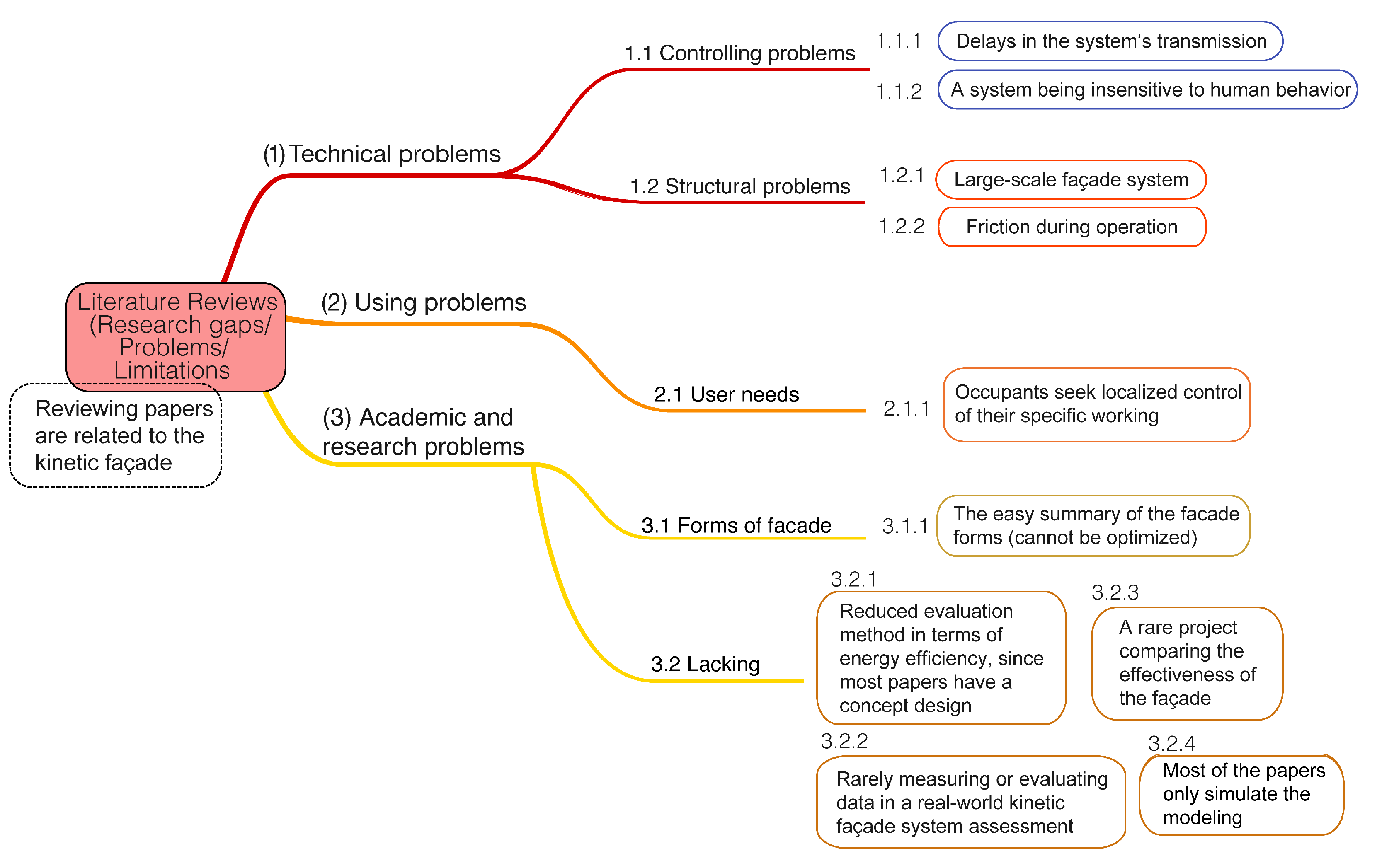
Figure 3 shows the gaps in the literature review related to this study. The study was divided into three parts: (1) technical problems, (2) usage problems, and (3) academic and research problems.
Firstly, (1) technical problems have been separated into two parts: (1.1) controlling problems and (1.2) structural systems.
(1.1) Controlling problems have two issues, as follows:
(1.1.1) Delays in the movement of a system. This problem occurs when the façade system does not directly respond to stimulus factors such as environment and human control [4,17,18,19,20].
(1.1.2) A system does not to respond to human behavior. This issue links to 1.1.1 and 1.1.2, which occur when the system is not connected to the environment; thus, it affects users in terms of their use of the space in the indoor area not being satisfactory [4,17,18,19,20,21,22].
(1.2) Structural problems have two gaps, which are as follows:
(1.2.1) The large system in the façade. One of the problems of the kinetic façade is that the system is not compact; this makes the façade challenging to install [4,17,19,20,23].
(1.2.2) The friction problems during operation relate to the problem of control; therefore, when designing the overall system, the control elements are crucial in reducing the friction issue [17,19,20,24,25,26].
Secondly, (2) usage problems have an issue regarding (2.1) user needs, wherein there is a gap in which occupants seek localized control of their specific working, living, or learning environment. This problem relates to human behavior since, every person has a different purpose for using the space—not only in terms of working but in utilizing it as a multi-purpose space. In this issue, the kinetic façade should be able to be adapted to use. For instance, users can control the kinetic façade via an application instead of automatically adjusting the sunlight intensity. Although there is a different objective in this study, we have a guideline for the use of a kinetic façade for various purposes in the last topic [18,19,21,27,28,29].
Thirdly, (3) academic and research problems have two significant issues, namely, (3.1) gaps in the forms of the façade and (3.2) lacking issues.
(3.1.1) The forms of the façade have a gap that is easy to summarize in terms of the façade forms. Since it does not include optimization issues, in this study, we simulated many forms of the potential of the façade for comparison with the kinetic façade in a new design in terms of daylight factor (DF).
(3.2) The lacking issues were divided into four gaps, as follows;
(3.2.1) There are few evaluation methods in terms of energy efficiency since most papers have a concept design [17,20,30].
(3.2.2) There are few measurements or evaluation data regarding real-world adaptive façade (AF) system assessment [17,19,29,30,31,32,33,34,35,36,37,38].
(3.2.3) It is rare for projects to compare the effectiveness of façades [17,20,32,34,35,37].
(3.2.4) Most of the paper only simulates modeling in the software [17,18,32,35,36].

2.2. Daylight Factor

In this study, the daylight factor (DF) and LEED version 4.1 requirements were simulated using Climate Studio; the software is the fastest and most precise form of environmental performance analysis for the architecture, engineering, and construction industries. The daylight factor is a part of daylight availability; there are several factors for evaluating the light for a different purpose. However, this article focused on three indicators: the daylight factor (DF), spatial daylight autonomy (sDA), and annual sunlight exposure (ASE). First, the daylight factor (DF) quantifies the quantity of available daylight in a space as a percentage (on a work plane); the purpose of this study is to determine the façade’s ability to protect the direct sunlight in the space; thus, the daylight factor is an adequate indicator of the façade’s capabilities. Second, the spatial daylight autonomy (sDA) and annual solar exposure (ASE) are indicator criteria for LEED version 4.1. To obtain the LEED credit, the points are based on all qualifying areas’ total spatial daylight autonomy (sDA). Zones that receive an excessive amount of direct sunlight are immediately excluded. Therefore, this criterion can preliminarily indicate whether humans can accept natural light in a working space.

2.2.1. Formula Expression

Daylight factor (DF) is a common and straightforward method for measuring the perceived daylight quality in a room. This is the ratio of outside illumination to interior illumination, represented as a percentage. The greater the DF, the more natural light a room receives; rooms with an average DF of 2% are considered daylit. However, a space is only supposed to have good natural lighting when the DF is greater than 5% [39,40,41], as described in Table 1.
The formula is expressed as Equation (1):
D F = 100 × E i n E e x t
In Equation (1)
  • Ein is interior illumination at a fixed location;
  • Eext is horizontal outdoor illuminance under an overcast (CIE sky) or uniform sky.
The brightness of an overcast standard (CIE sky) varies with altitude. For example, the zenith is three times brighter than the horizon. This study used an overcast (CIE sky) to evaluate the potential of a kinetic façade to filtrate daylight into the indoor space.
Overcast (CIE sky) is often suggested in the simulation method since this type of sky represents the worst-case scenario when compared with other sky types [42]. In this condition, we can determine the façade’s ability to protect direct sunlight and provide suitable sunlight to the working spaces defined, as in Figure 4 (part c), looking at a glass façade, static façade, kinetic façade (version 1: rotating movement), and kinetic façade (version 2: twisting movement). In order to analyze the ability to adapt to sunlight, the kinetic façade (version 2) was simulated under the same conditions as other façades in the worst-case scenario, before testing the kinetic façade (version 2) in an actual situation with various sky types.

2.2.2. LEED Version 4.1 Criteria

LEED version 4.1 criteria are the next-generation standard for green buildings’ design, construction, operations, and performance. They promote buildings, concentrating on efficiency and leadership in order to deliver triple-bottom-line returns for people, the planet, and profit. LEED version 4.1 increases building standards for energy efficiency, water conservation, site selection, material selection, daylighting, and waste reduction. This study focused on the daylight factor (DF). The compliance options when evaluating LEED version 4.1 are separated into two measurements: daylight simulation and actual measurement [43].
Firstly, daylight simulation is divided into two options. Option 1 uses simulation to demonstrate that spatial daylight autonomy (sDA) specifies the percentage of the area that satisfies minimum daylight illuminance levels for a specified fraction of the working hours per year; at least 55 percent of the space achieves sDA. In addition, the annual sunlight exposure (ASE) indicator reveals the possibility of visual discomfort inside work environments. For LEED version 4.1, space cannot exceed 10 percent.
Option 2 uses a simulation to demonstrate that illuminance levels between 300 and 3000 lux are achieved between 9 a.m. and 3 p.m. at the equinox.
Secondly, actual measurement (option 3) uses actual measurements to demonstrate that the illuminance levels for 75% of the space are between 300 and 3000 lux. In this study, both daylight simulation (option 1) and actual measurements (option 3) were required to assess the potential of the kinetic façade (version 2: twisting movement).

3. Research Methodology

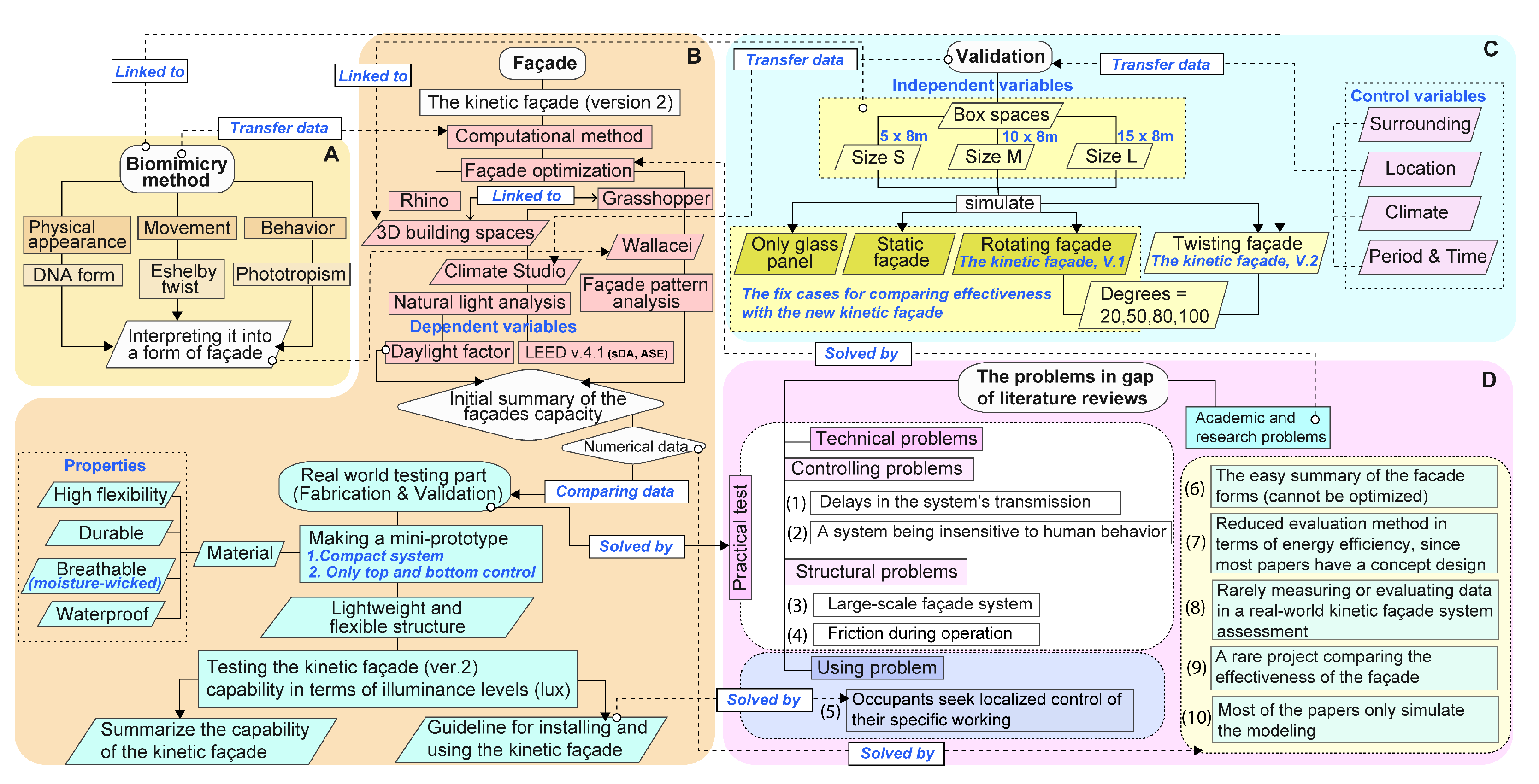
Figure 4 illustrates the overall diagram of the research methodology. It has four major sections: (A) biomimicry processes, (B) the kinetic façade part, (C) the validation part, and (D) the problems in the gap in the literature reviews. Firstly, the biomimicry process has three parts to integrating the distinctive part of nature into a kinetic façade, which are the physical appearance of DNA, the movement from the Eshelby twist, and the behavior of the phototropism phenomenon. These elements are interpreted as kinetic façade forms via a computational method in part B. Part B is the kinetic façade part that inputs the data from part A and part C to simulate the kinetic façade. This process uses a computational method for façade optimization that uses software for the simulation, namely, Rhino and Grasshopper. Rhino is used to build 3D building spaces to plug in the kinetic façade, and Grasshopper uses two plug-ins, namely, Climate studio and Wallacei. Climate studio, the most precise program for analyzing environmental performance, uses natural light analyses regarding daylight factor (DF) and LEED version 4.1 criteria. Wallacei, an evolutionary engine that enables users to simulate evolution, is used to analyze suitable façade patterns. After this, we summarize the capability of each façade type; only glass panels, static façade, kinetic façade (version 1: rotating movement), and kinetic façade (version 2: twisting movement). In this regard, the three façade types were taken as a comparative case study unrelated to the biomimicry approach: only glass panel, static façade, and kinetic façade (version 1: rotating movement). Only the kinetic façade (version 2: twisting movement) must input the data obtained by observing the natural identity of Wallacei software to generate the façade forms needed to simulate the façade capabilities in the Climate studio part with the three façade cases. After summarizing the data in the simulation, the next step is the real-world testing part, which involves fabrication and validation. This step creates a mini prototype of a kinetic façade that uses material of high flexibility, durability, and breathing ability (moisture-wicked), as well as being waterproof. Since there is a purpose to making this prototype lightweight and easy to maintain, these properties can enhance the technical problems in the literature review gaps. For example, the lightweight prototype can enhance the delay in the system’s transmission, and friction during operation means that the system is operating better.
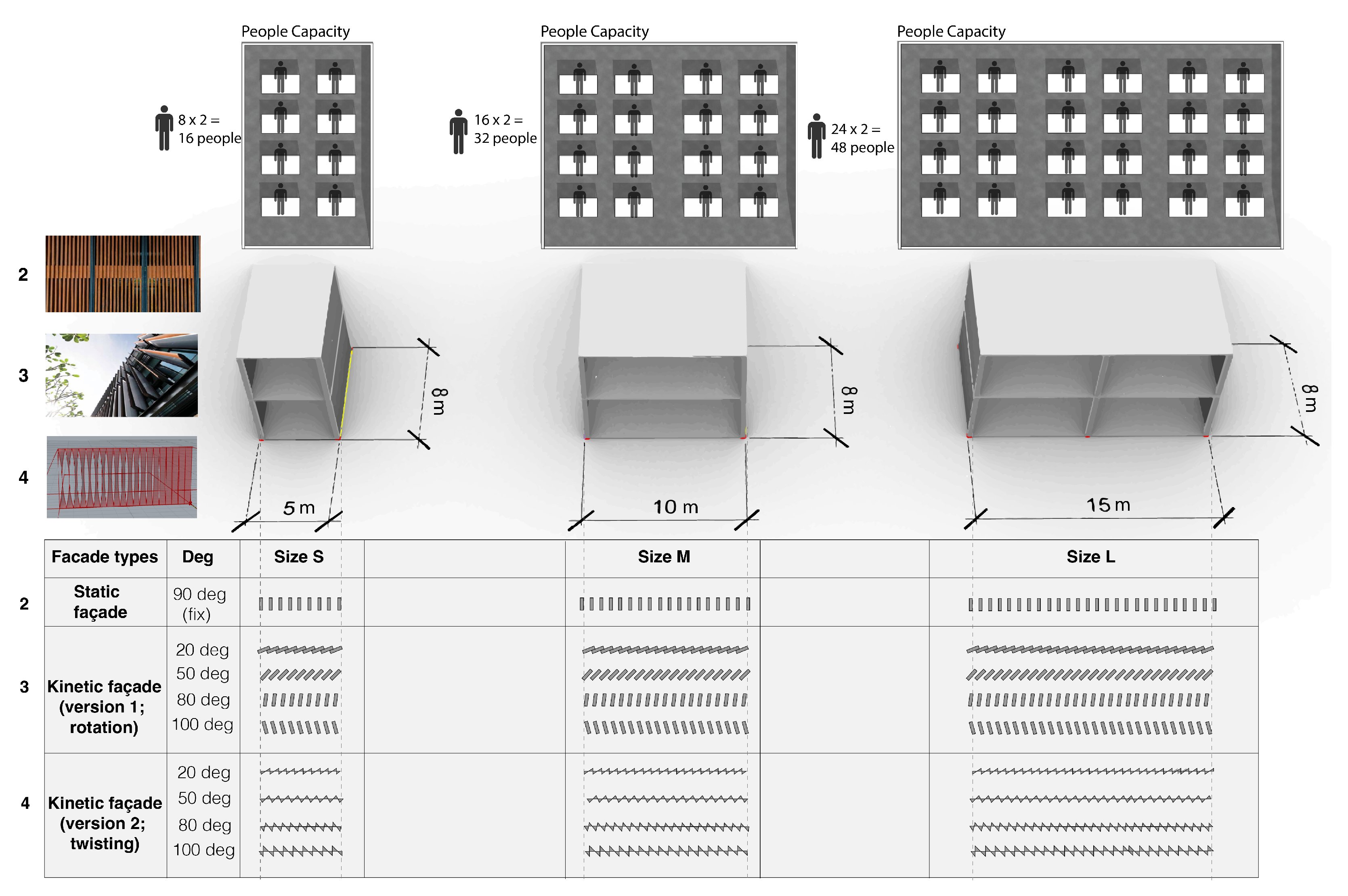
Furthermore, the mini prototype must have a compact system; only the top and bottom are used to control the façade since the target for a combination of the material and controlling system must be a lightweight and flexible structure to respond to the practical test in the literature review gaps. Thirdly, part C is the validation part. This study used the box spaces for simulation, which are sizes S (5 × 8 m), M (10 × 8 m), and L (15 × 8 m), by using the different types of façades to plug-in and simulate the façade capabilities, which are a glass panel, a static façade, and a kinetic façade (version 1: rotation movement) with 20 deg, 50 deg, 80 deg, and 100 deg, as well as a kinetic façade (version 2: twisting movement). The kinetic façade version 2 also experiments with 20 deg, 50 deg, 80 deg, and 100 deg. All steps must respond to the problems in the gap in the literature reviews in part D, which are as follows:
  • Delay in the system’s transmission, solved by a real-world testing part;
  • A system is insensitive to human behavior, solved by a real-world testing part;
  • Large-scale façade system, solved by a real-world testing part;
  • Friction during operation, solved by a real-world testing part;
  • Occupants seek localized control of their specific working, living, or learning environment. The guideline in this article clarified this gap for installing and using the kinetic façade, since the kinetic façade can be adjusted for any purpose of the user. For example, if users do not want the kinetic façade to move automatically according to sunlight, the façade can be adjusted by human control;
  • The easy summary of the facade forms (cannot be optimized), which is solved by comparing numerical data to real-world testing and simulating data;
  • Reduced evaluation method in terms of energy efficiency since most papers have a concept design that is solved by comparing numerical data with real-world testing and simulation data.
  • Rarely measuring or evaluating data in a real-world kinetic façade system assessment, which is solved by comparing numerical data with real-world testing and simulation data;
  • Rare projects comparing effectiveness, which is solved by comparing numerical data with real-world testing and simulating data;
  • Most papers only simulate modeling, which is solved by conducting experiments in the real world.

Comparing the Effectiveness of the Façade

Figure 5 summarizes the factor used to compare the effectiveness of each façade type in the research methodology; the data were collected to compare the efficacy of the façade by simulating the space in the same condition, focusing on daylight factor and LEED version 4.1 criteria. The variables are as follows:
  • Independent variables:
  • Only glass panels;
  • Static façade;
  • Kinetic façade (version 1: rotating movement);
  • Kinetic façade (version 2: twisting movement);
  • Box spaces: size S, M, and L.
  • Dependent variables:
  • Natural light focused on the daylight factor;
  • LEED version 4.1 criteria concern spatial daylight autonomy (sDA) and annual sunlight analysis (ASE).
  • Control variables:
  • Surrounding: No existing buildings nearby, and the same zone for the simulation;
  • Location: Bangkok, Thailand;
  • Climate: Overcast sky;
  • Period: Daylight—annual period analysis, time analysis (from 8:00 a.m. to 6:00 p.m.).

4. Biomimicry Part

4.1. Translating the Biomimicry Method to the Kinetic Façade Idea

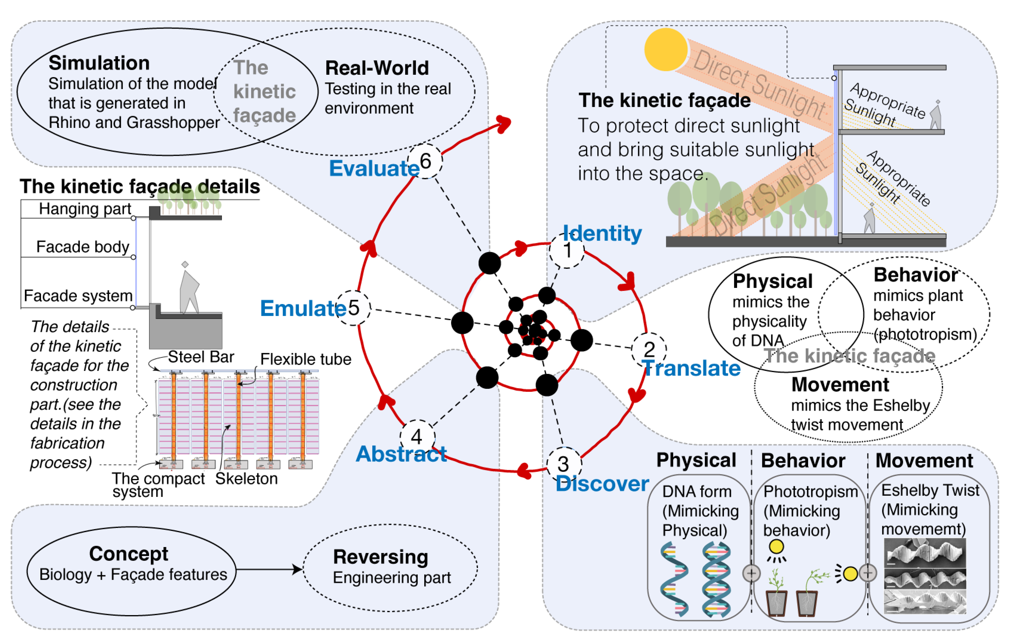
Biomimicry brings modern ideologies closer to nature by using nature as a design inspiration to tackle human problems in a sustainable manner [44]. Biomimicry connects the constructed environment to the natural world by emulating, measuring, and learning from Mother Nature. This strategy is based on the idea that “the more our environment resembles the natural world, the more likely it is that we will be accepted on this home that is ours, but not ours alone” [45]. Carl Hastrich created the biomimicry design spiral in 2005 [46,47]. This is a step-by-step process for transforming the ideas of nature into innovative and sustainable design solutions. Biomimicry processes were compounded into six processes, namely, (1) identify, (2) translate, (3) discover, (4) abstract, (5) emulate, and (6) evaluate. This process clarified each step in this study, as shown in Figure 6. Firstly, the identity process identifies the functions in design that need to be performed. This study aimed to create a kinetic façade that can adjust itself according to the sunlight intensity. Thus, the researchers must find the nature identity that has the potential to respond to sunlight, both physically and as a system of nature, in order to transfer ideas to the next step. This study selected three natures: DNA, phototropism, and Eshelby twist. Secondly, the translating process integrates the biological ideas selected from the identity process, such as DNA, phototropism, and Eshelby twist. These natures must be translated into the main features, namely, physical aspects, behavior, and movement of nature. First, DNA is selected for the physical set, since DNA has a complex structure that can twist the form by stimulus [48]. Second, phototropism is selected for the behavior set, since this feature is crucial for plants that respond to sunlight; thus, this feature can also apply to the kinetic façade feature. Third, Eshelby twist movement is the natural movement phenomenon from nanowires. The twisted form is similar to a pine tree with a hierarchical twist; the stimulus affects each twist movement [49]. These three natural identities must be integrated to transfer the uniqueness to the kinetic façade innovation. Thirdly, the discovery process is finding the strategies of nature. This study had three components to accomplishing the kinetic façade target: physical environment, behavior, and movement. First, the idea of physical aspects stems from the physical DNA structure that will be the main structure of this innovation; since the DNA form is flexible, it can respond to the aim of this study, which is that the façade is flexible to respond to sunlight. Second, behavior is viewed in light of the phototropism phenomenon of plants that want to receive sunlight; this phenomenon is a beneficial feature for the kinetic façade and can adjust itself according to the sunlight intensity. Third, the Eshelby twist is the phenomenon of a nanowire pipe tree with a twist; it is a fascinating movement with a hierarchical twist. This twist is caused by interference from external stimuli, resulting in a progressively higher degree of twist. This movement can be integrated into the DNA structure to develop into the engineering part. Fourthly, the abstract process reverses the ideas from the previous three steps and applies them to the engineering section, making them applicable to responding to sunlight and installing buildings. This study must translate the integration concepts between nature and kinetic facade identity into a practical, operational procedure. In this section, controlling devices are crucial to experiment with, especially IoT devices such as Arduino boards, light-intensity sensors, servo motors, etc. The section concludes with a detailed description of the fabrication process section. Fifthly, the emulate process explores the kinetic façade components in the construction part; this process directly connects to the abstract part, since it is also an engineering section. However, this part contains more details of the kinetic façade elements that are also described in the fabrication process section: façade ideas for installation. Finally, the evaluation process: in this study, the performance of the kinetic facade is compared with the simulation method and the real-world testing method to determine the performance of the kinetic façade both ways, especially the real-world testing method, which can identify the limitations of innovation for improvement and development in the future.

4.2. Analysis of the Probability of Façade Forms (Phase 1)

This section analyzes the likelihood of façade patterns being influenced by the physical DNA, phototropism behavior, and Eshelby twist to design the strip form. Wallacei, an evolutionary algorithm software for producing algorithm forms, was used to generate this. Evolving algorithms are a collection of optimization algorithms that mimic the mechanisms of natural evolution [50].
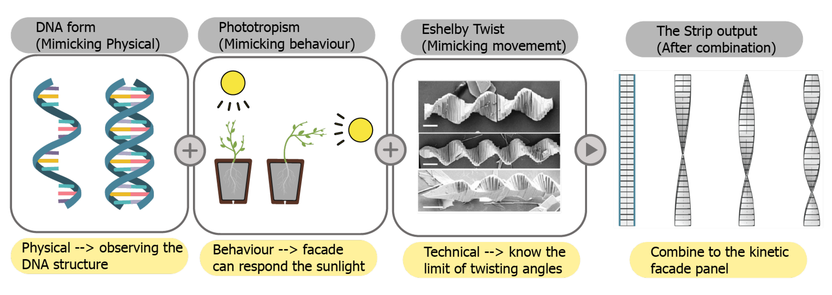
Figure 7 shows the process of generating the strip, which has three components: the physical DNA structure, phototropism behavior, and the Eshelby twist. First is the DNA form; this study mimicked the physical DNA form, namely, its structure. Second is the phototropism phenomenon, found by observing the phototropism behavior of plants. Plants adjust their trunk to sunlight for photosynthesis. This is stimulated by photoreceptors related to signaling mechanisms. In addition, plants modify their development characteristics in response to environmental influences, such as the amount of available sunshine [51]. Third is the Eshelby twist, understood by studying the movement of nanowires that can twist themselves according to the environment, which is a beneficial for a technical application that can learn the limit of twisting angles, and is effective for preventing sunlight. These factors are crucial when interpreting the façade strip mechanism since every component has a dominant feature to prevent sunlight, making the building effectively unique.
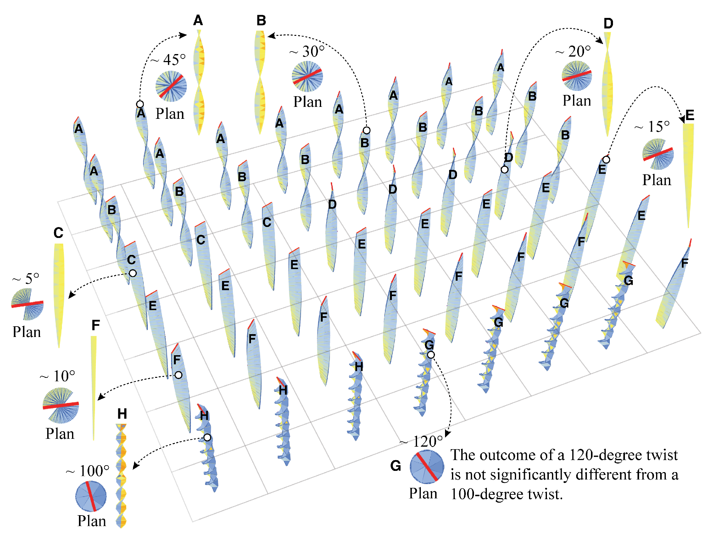
Figure 8a depicts the strip phenotype probability patterns in the standard deviation (SD) graph, resulting in 450 solutions from generations 0 to 8. When compared to other generations, each generation differs and repeats patterns. For example, generation 0 and generation 5 share some strip patterns. However, the strip patterns that result from the phenotype are distinct, resulting in a range of strip phenotypes that are shown in the slope of each generation. For example, in Figure 8 generation 0 has a higher slope than generation 8, meaning that generation 0 is more diverse in terms of strip forms than generation 8. The strip pattern diversity also relates to the image shown in Figure 8b, the mean value trendline illustrated in the slope pattern; this has a declining graph, which means the strip forms have less diversity in the latest generation. The strip phenotype is produced by simulating the DNA structure, phototropism phenomenon, and Eshelby twist movement [52] to reproduce the characteristics of strip patterns for use in the kinetic façade model. Phenotypes are the observable characteristics of an individual that result from the interaction between its genotype (total genetic inheritance) and its environment. Observable characteristics include behavior, biological qualities, color, shape, and size [53]; for instance, the same bird species has a different physical appearance (phenotype) in a different region [54]. Therefore, the phenotype is a simple indicator when observing the strip forms of the façade. For instance, Figure 9 shows the probability output in 50 solutions of a strip phenotype in generation 3; there has different and the same strip forms in this generation. This simulation has eight patterns (phenotype) with different degrees, which are 5 deg, 10 deg, 15 deg, 20 deg, 30 deg, 45 deg, 100 deg, and 120 deg, respectively. The overall result is 450 solutions, which are paused to generate the phenotype in Wallacei software since, when looking at the trend of SD in eight generations, as shown in Figure 8a, the slope of the last generation is less than that of the first generation. This indicates that the strip phenotype is repeated in the same patterns—this serves no purpose when generating for the next generation. A low standard deviation indicates that most results are comparable (less variation within the population). On the other hand, a high standard deviation indicates that the results are further from the mean, with more variation within the population [52]. When the SD graph is examined, the earlier generation displays a greater variety of strip patterns than the most recent generation.
To summarize generation 0 through generation 8, the strip patterns are applicable to the kinetic façade concept. Figure 9 can be used to select the proper degrees of strip pattern; the third generation has varied degrees. However, the degree of twist at 120 degrees is not appreciably different from the twist at 100 degrees. This degree has no effect on sun-shading that differs from 100 degrees. Therefore, the degrees were chosen to apply in the range from 0 to 100 degrees for the kinetic facade. The potential to shield the sun at various times depends on the varying strip pattern angles. Thus, adapting to user needs in various conditions when living in a space is advantageous since the strip will twist more when the light intensity is as low as a strip H: 100 deg.

4.3. Analysis of Natural Light Ambience (Phase 2)

Figure 10 shows the setting-up node for the simulation in the box spaces. The node is crucial for simulating the daylight factor. Therefore, we set the node position close to the human eye, approximately 1.10 m high, which is a very sensitive distance, to simulate the daylight factor [55] when performing work activities. This node level uses every size of the box. If we know the daylight level in this position, we will compare and develop the façade in future issues.

5. The Validation of the Façade

5.1. Simulation Processes

Figure 11 illustrates the box spaces for the simulation in terms of daylight factor (DF) and LEED version 4.1 criteria in terms of the different sizes of boxes that must be installed in the façades of different types for the simulation, including:
  • Only a glass panels;
  • Static façade, which is 90 deg (fixed angle);
  • Kinetic façade (version 1: rotating), which 20 deg, 50 deg, 80 deg, and 100 deg;
  • Kinetic façade (version 2: twisting), which 20 deg, 50 deg, 80 deg, and 100 deg; this type of façade was explored efficiently in this study, particularly in terms of the natural light allowed into the space.
The reason for simulating the boxes in different sizes is to know the effects of sunlight entering the area and how much of a difference there is when simulating the difference between the façade and area sizes. The box sizes refer to the dimensions of the home office, with sizes S, M, and L. The approximate capacities of people in the space of sizes S, M, and L are 16, 32, and 48 people, respectively. This study varied only in terms of the width dimension; the depth was fixed, since the depth affects the accessibility of sunlight. Furthermore, it was beneficial to simulate the criteria for a green building in terms of LEED version 4.1. Therefore, each space was assumed as an office of different sizes, which is beneficial for initial prediction to pass or fail the criteria.

5.2. Results of the Daylight Simulation

Comparing a Façade of All Types

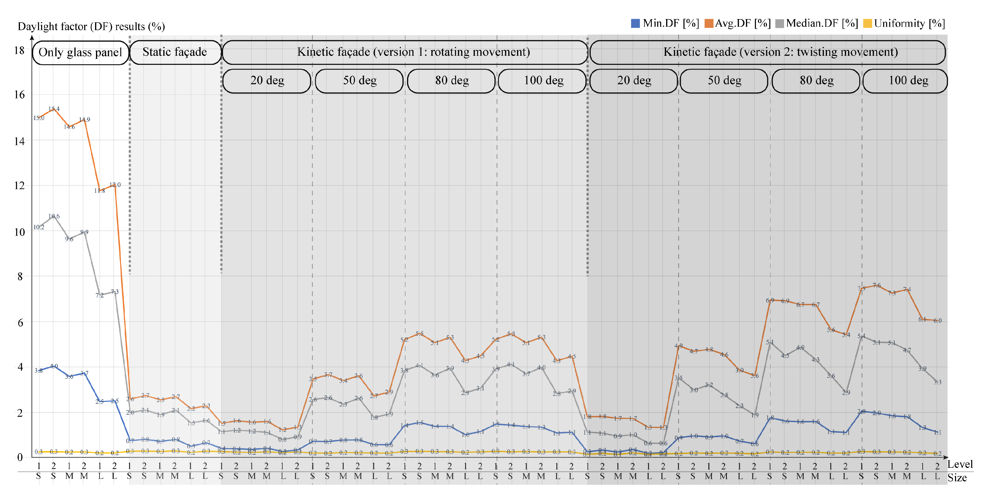
Figure 12 summarizes the simulated daylight factor (DF), referred to in Figures S1–S10 in the Supplementary Material. The bar graph was split by size and degree when comparing all façade types. First, the glass panel alone had the maximum daylight factor compared to the other building envelopes, at 50 deg, 80 deg, and 100 deg. The static façade had a lower daylight factor than the kinetic façade versions 1 and 2. Excluding 20 degrees for both kinetic façades, the kinetic façade version 1 in 20 degrees had the lowest daylight factor, followed by the kinetic façade version 2 in 20 degrees. When concentrating on the kinetic façade versions 1 and 2, it was clear that kinetic façade version 2 had a somewhat greater average daylight factor than the kinetic façade version 1. This indicates that the kinetic façade (version 2: twisting movement) can bring more natural light into areas of any size in comparison with the kinetic façade (version 1: rotating movement).

5.3. The Results of LEED Version 4.1 Criteria

Table 2 illustrates the result after simulation of the glass panel alone, the static façade, and the kinetic façade (version 1; rotating movement) in terms of LEED version 4.1 criteria. First, the glass panel alone exceeded daylight in spaces of every size; the easy factor for analysis of ASE is that standard daylight for human comfort in daylight in the working space should not exceed 10% in the area. Second, in contrast, the static façade makes it challenging to let natural light into the room since this façade design is too compact; thus, artificial light must be installed into the space instead. Third, the kinetic façade (version 1; rotating movement) can admit appropriate sunlight into some spaces: the output is that ASE can accept users working in the space that can pass the LEED version 4.1 criteria. However, some areas are too dark for a person to perform in. For instance, the 20 deg of the kinetic façade (version 1; rotating movement) in every space’s ASE was 0%, too dark to use natural light, or, in some areas, 100 deg, too dark in terms of natural light in the large level 1 (L1), small level 1 (S1), large level 2 (L2), and small level 2 (S2). This implies that the size of the area and the height of the building have an impact on ASE. Therefore, it is vital to consider the installation of the types of facades and the number of facades that will be installed with the building envelope according to its volume.
Table 3 illustrates the result of the kinetic façade (version 2: twisting movement) in terms of LEED version 4.1 criteria, wherein the difference in degree represents the dynamic of the kinetic façade. This shows that some degrees exceeded the standard criteria in ASE, since the excellent conditions should not exceed 10% in the space because this makes users uncomfortable when working. Thus, we solved this problem by changing the movement of the kinetic façade from moving with the same angle in one panel to moving with a different angle in one panel, as shown in Figure 13. In other words, each strip of the kinetic façade freely moves to provide suitable sunlight.
We summarized all the façade types in LEED version 4.1, along with the simulation results for each façade type: glass panels only, a static façade, a kinetic façade (version 1), and a kinetic façade (version 2), see Figure S11 in the Supplementary Material. This met the LEED version 4.1 criterion for the lowest amount of daylight that can enter a space. In addition, all façades met the LEED version 4.1 requirements (3 credits) for natural light transmission. This criterion benefited the design of a kinetic façade that sought to shield the sun, as demonstrated by this study. If the kinetic (version 2: twisting movement) passes the LEED version 4.1 measures, it will obtain the minimal amount of sunlight required by the criterion, which makes human activities in the spaces more efficient. However, the ASE could be concerned with the next step, as a standard should not exceed 10% of the spaces.

Improving the Potential of the Kinetic Façade (Version 2: Twisting Movement)

Figure 13 shows the improvement potential when providing suitable sunlight in the working space in terms of the kinetic façade (version 2: twisting movement). It focuses on the movement of the façade from the same degree in one panel to different degrees in one panel to freely move in each strip with regard to sunlight intensity.
The result of improving the kinetic façade (version 2: twisting) in terms of LEED version 4.1 is referred to in Figure S12 in the Supplementary Material, which shows sDA, ASE, and average lux. Evidently, improving the strip movement by freely moving to each strip is better in terms of output to provide suitable sunlight into the space, as opposed to moving with the same pattern in one panel, and since the first factor of concern in this step is ASE, it should not exceed 10% in the space; this output ASE is 8.0% of all areas, which is acceptable for the users in the space.

6. The Fabrication Process

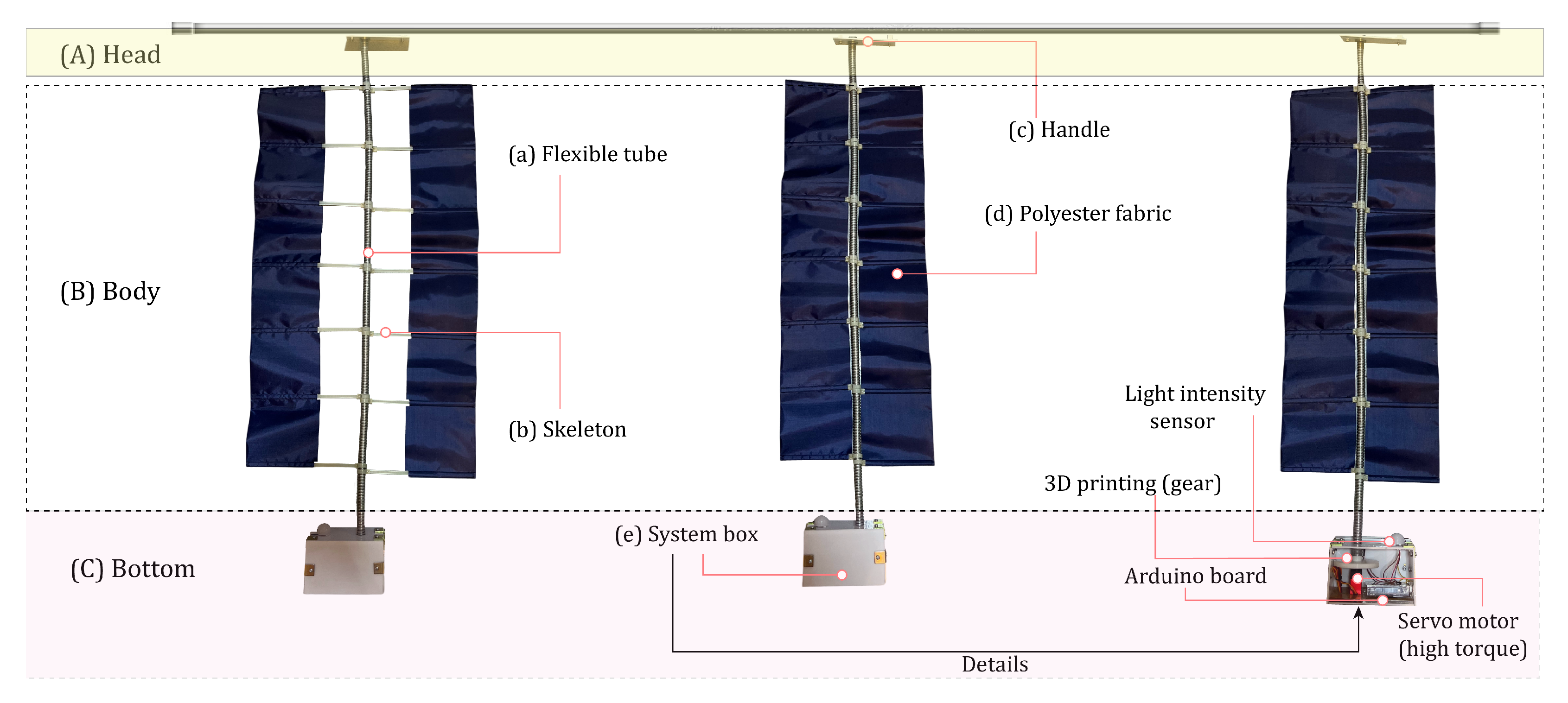
Figure 14 illustrates the kinetic façade (version 2: twisting movement) model for fabrication in the 3D model. It has three major components: (A) head, (B) body, and (C) box system. The minor component compounds with the fifth element are as follows: (a) the main structure for installation into existing windows, which is a part of the head of the whole system; (b) the skeleton for supporting the fabric; and (c) flexible fabric that uses polyester fabric, since it has a material property that is fixed in the methodology, with high flexibility and durability, and is breathable (moisture–wicked) and waterproof. In addition, there is (d), a flexible tube that is a significant element when changing the degree of the façade; these parts are part of the body of the whole system. Finally, the last part (e) is the bottom part; this part compounds with the box system of the façade, which is the crucial part for controlling the body.

Façade Ideas for Installation

Figure 15 shows the kinetic façade (version 2: twisting movement) elements that have five components for controlling the body when twisting, namely, (a) flexible tube, (b) skeleton (cable tile), (c) handle, (d) polyester fabric, and (e) system box (controller). We designed the kinetic façade as a module system that is easy to install, whose elements can easily be changed. Firstly, in terms of installation purposes, each user has various needs, such as requiring only one window panel for personal shading or a whole panel of the building, and this façade can respond to the user’s need. Secondly, when changing the façade’s elements, one of the problems with architectural components is the difficulty in replacing parts when they expire. Thus, this façade is designed to be easily changed in terms of its material, especially the fabric, in order to protect the short-life product from sunlight.

7. Results and Discussion

The standard EN 12464 light and lighting can be used as a reference [56]. Depending on the activity, the recommended light level for office work in indoor workspaces is between 500 and 1000 lux. The light level may reach up to 1500–2000 lux for precise and thorough work. However, in this study, a lux range between 500 and 2000 lux was deemed appropriate, since it provided a wide range to cover the scope of various tasks.

7.1. The Results of the Kinetic Façade (Version 2: Twisting Movement) before and after Installation

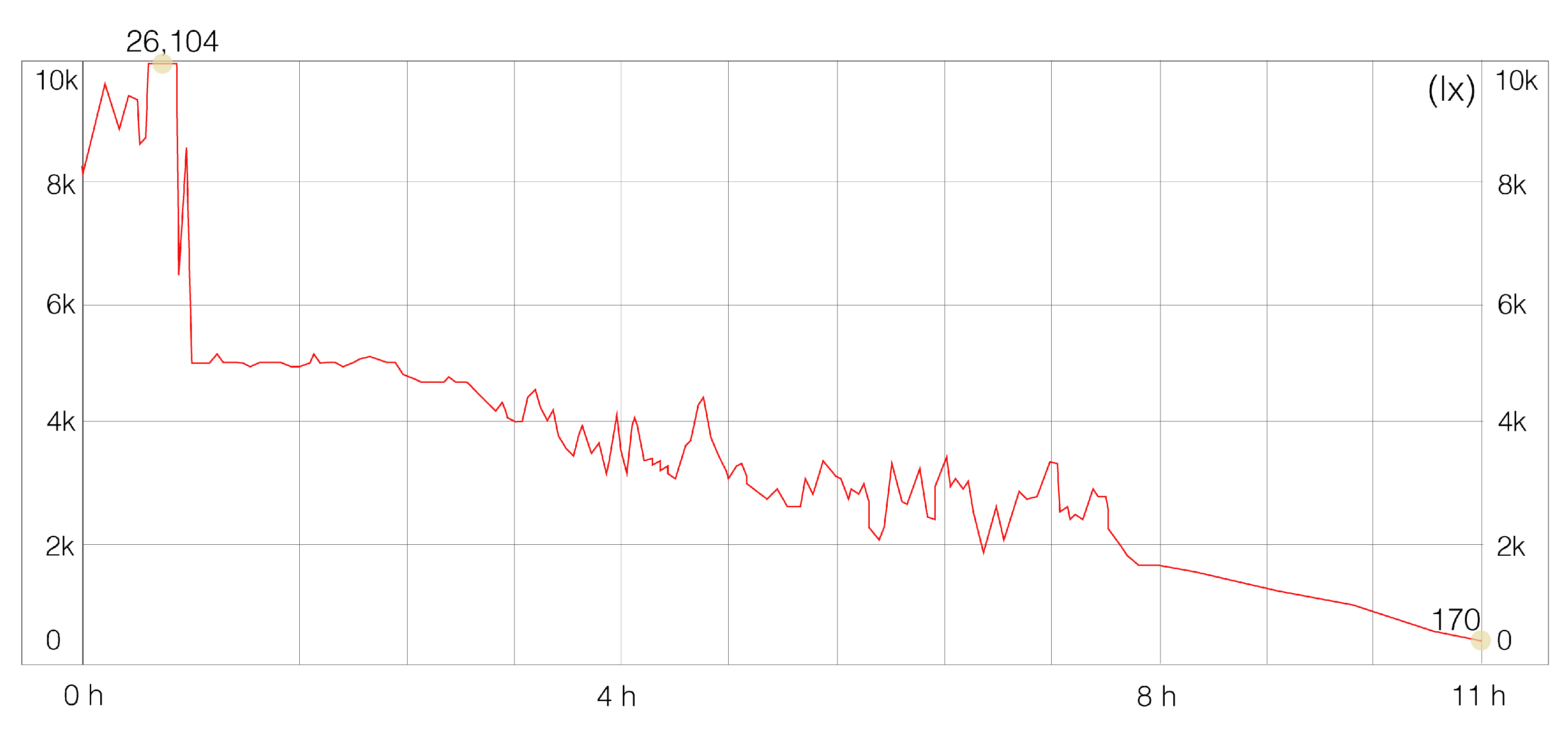
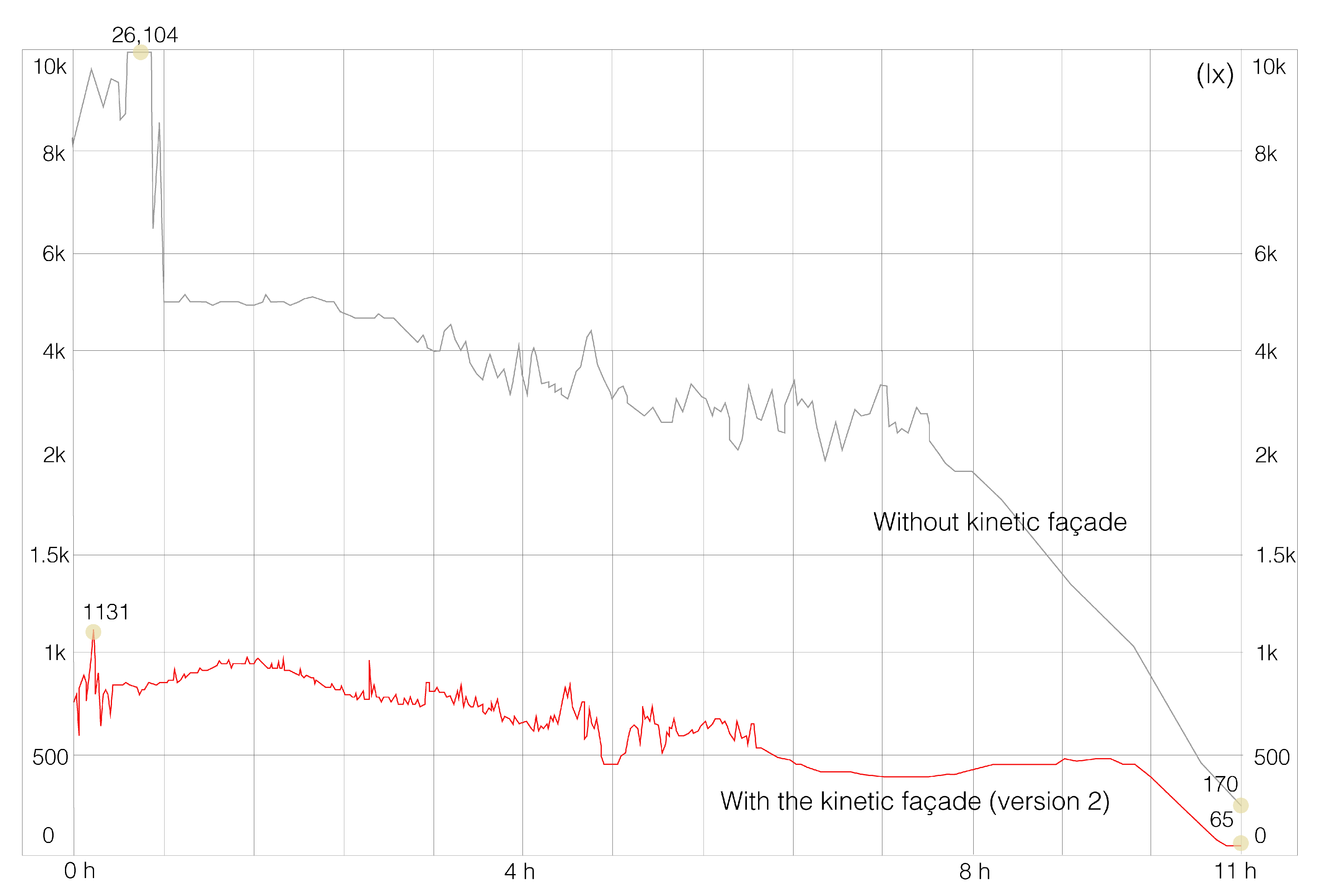
Figure 16 shows the testing results in the actual space situation without the kinetic façade. The result is an excess of daylight in the space, particularly in the morning period between 8:00 a.m. and 11:00 p.m.; at 8 a.m., this reached a peak of 26,104 lux.; this harms human health, especially eye health, and affects work efficiency.
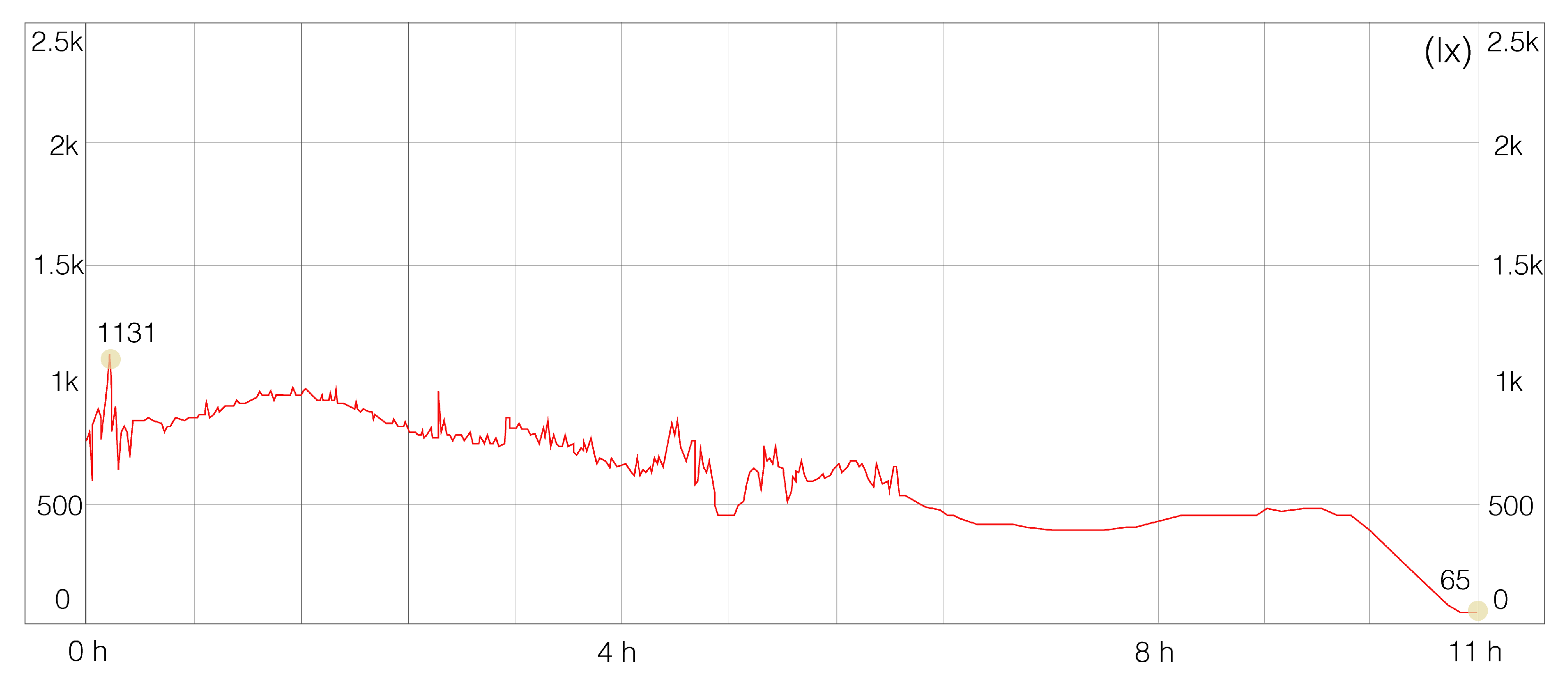
Figure 17 shows the results of testing the actual situation after installing the kinetic façade. The result effectively reduced the daylight in the area, especially in the morning period that peaks at 8:00 a.m., at approximately 26,104 lux. This was reduced to 800 lux, which was suitable for the users in the space.
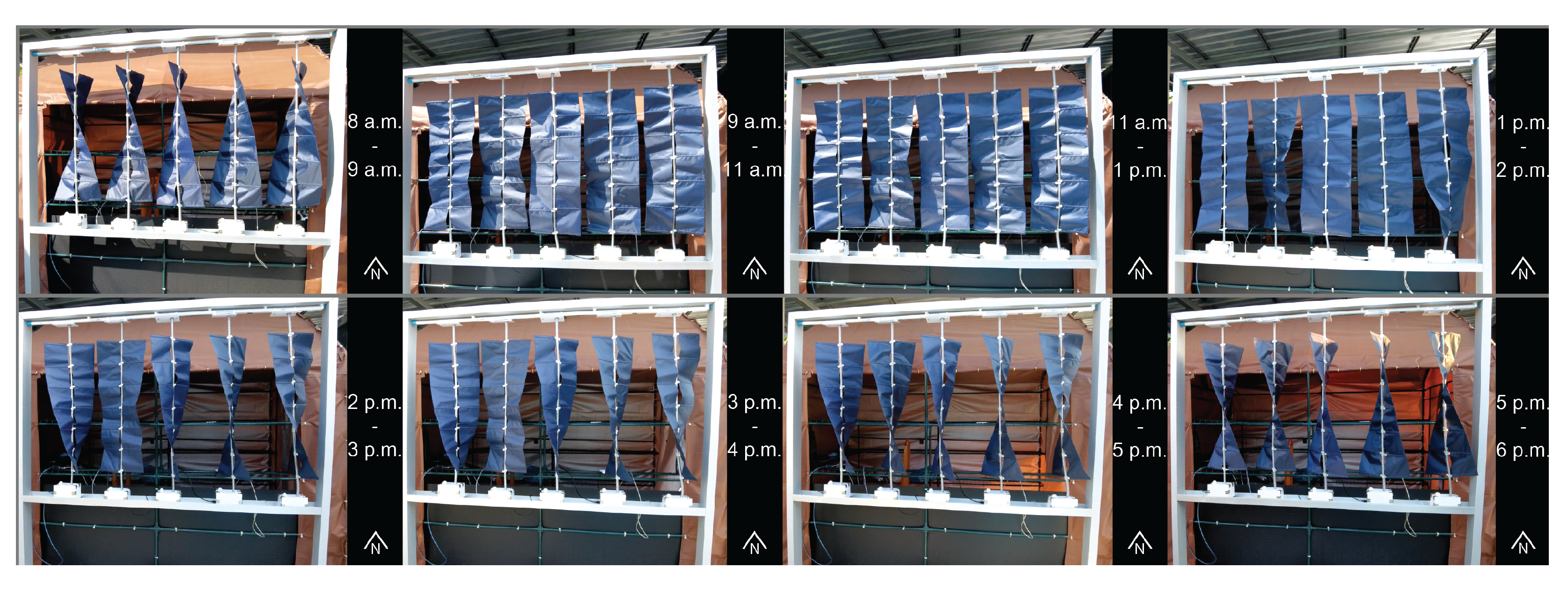
Figure 18 illustrates the kinetic façade (version 2: twisting movement) at a record of movement at different times of the day between 8.00 a.m. and 6.00 p.m., with a time-lapse technique for observing the kinetic façade behavior. The result is that the kinetic façade was able to respond to the sunlight at different angles related to sunlight intensity on the testing day.
Figure 19 illustrates the comparison line graph for both the space without the kinetic façade and the space with the kinetic façade. The space with kinetic façade version 2 was dramatically decreased. Moreover, the lux values were suitable for working areas with an average range of 500–2000 lux for working activity areas. In contrast, compared with the space without a kinetic façade, there was excessive daylight in the space, particularly from 8:00 a.m. to 2:00 p.m.; this was over the limits for sunlight in working activity areas.
Referring to LEED version 4.1 criteria in option 3, which is an actual measurement, the illuminance level for passing the requirements is 75% of the space between 300 and 3000 lux. Table 4 illustrates the approximate lux values after installing the kinetic façade (version 2: twisting movement). This passed the LEED version 4.1 criteria since the space can receive between 300 and 3000 lux levels during office hours, from approximately 8:00 a.m. to 5:00 p.m.

7.2. Guidelines for Installing the Kinetic Façade (Version 2: Twisting Movement)

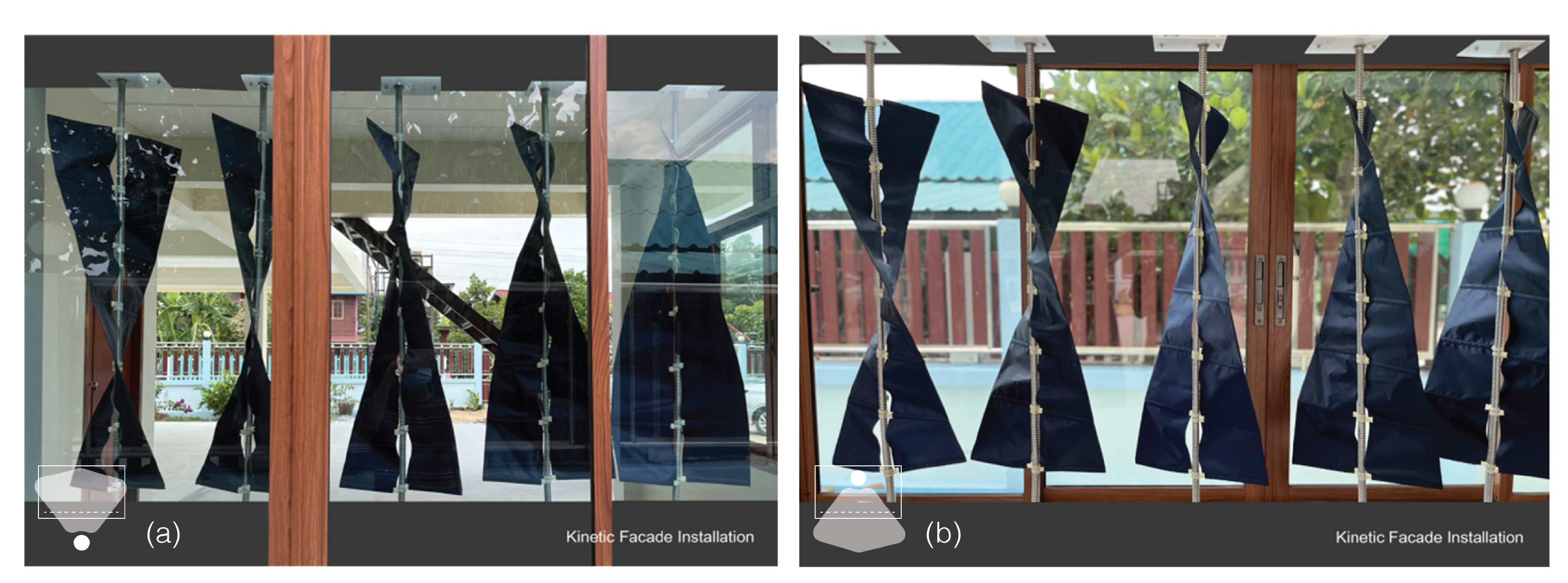
Figure 20 demonstrates a prototype of the kinetic façade (version 2: twisting movement) installation with the window areas. However, this is just one approach to installing the kinetic façade with the windows. In this paper, we designed an approach to adapting the kinetic façade in various solutions in terms of a human-made object.
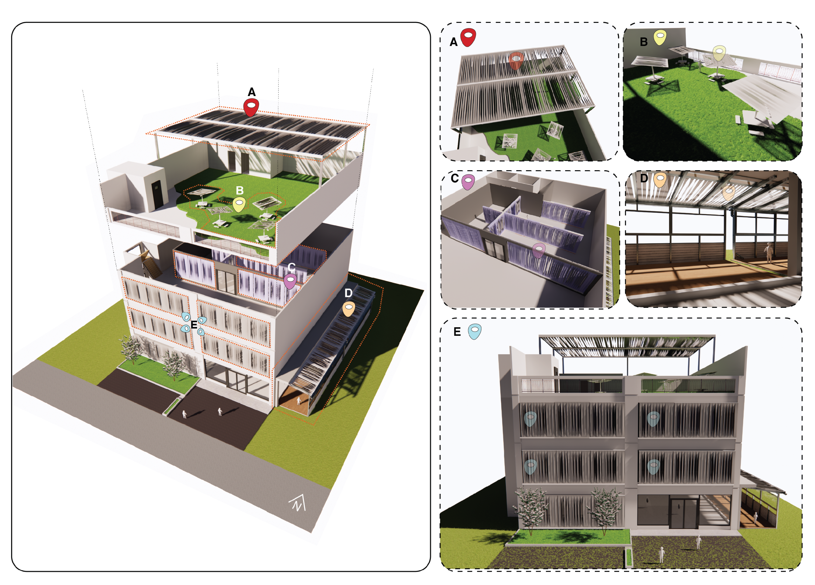
Figure 21 shows the guidelines for applying the various solutions. This study was illustrated in terms of five solutions, as follows: (A) the rooftop kinetic shading, (B) the kinetic parasol, (C) the kinetic partition, (D) the interior kinetic curtain shading, and (E) the kinetic façade (prominent for development in this study).
The first aspect to consider is (A) rooftop shading, for providing shade to users. This serves the same purpose as installing a façade plug-in with a building envelope that offers adequate sunlight. Second is a façade that moves and plugs into a parasol. Unfortunately, because this cannot alter the shading from sunshine during human use; the original parasol does not respond to human use. However, this invention can address this issue by adjusting the shade to correspond with the intensity of the sunlight. Third is a working station in the interior space with a kinetic partition. This innovation further filtrates the sunlight intensity through the working area.
Furthermore, it can provide a private space for users in the working place since it can adjust the degree of the strip. This can provide benefits to users in the working area, increasing productivity. Fourth is the interior kinetic curtain shading, a solution that has the same function as the rooftop shading, but is different with regard to the position for installation. This solution is located inside the space; thus, the function is similar to a curtain. The different places in which a kinetic façade is being installed can alter the materials being used; for example, the interior kinetic curtain shading could use a sophisticated fabric that is not waterproof. Finally, there is (E) the kinetic façade, which is the main innovation and solution and the focus of development in this study, which demonstrated the fabrication processes and was tested in actual situations. This can provide adequate sunlight through the spaces. This could also allow for adjustments of the kinetic shading according to user preferences.

8. Conclusions and Future Work

This research proposed a mimicry of the identity of natural phenomena to provide a kinetic façade innovation to filtrate sunlight into the working space. There are three components allowing for analysis of the natural phenomena: the physical DNA, phototropism behavior, and Eshelby twist movement can be interpreted using the biomimicry method in terms of strip forms, which are a part of the main component of the kinetic façade. The technical process for implementing this involves using Rhino and Grasshopper software to generate the possible strip forms and evaluate the potential of the kinetic façade system in terms of daylight factor (DF), including the sunlight intensity through the spaces and LEED version 4.1 criteria. The results after both simulations showed the possible strips and the evaluation of the kinetic façade potential to provide suitable sunlight. First, in the simulation of the possible strip forms, there were eight generations of the standard deviation (SD) trend graph. The overall number of strips was 450 solutions; however, most of the strip forms in each generation were repetitive forms, as shown in Figure 8a,b illustrating the trend of SD in eight generations and the mean value trendline of the strip forms. Evidently, both graphs continued to decrease in the latest generation, which meant they had a reduced strip form (phenotype) diversity. Therefore, the researcher would stop generating the strip phenotype in generation eight. For the strip form selection, the potential to bring suitable daylight into the space was crucial. Therefore, we chose 10 patterns with different degrees of twisting to obtain appropriate sunlight for each space in each period. The degree of evaluation, which can be converted to degrees, ranged from 0 deg to 100 deg.
To evaluate the entire kinetic façade system in terms of daylight factor (DF) and LEED version 4.1 criteria in two parts, we used a simulation and real-world testing. In the simulation section, the type of building envelope was divided into four types, which were (a) glass panel alone, (b) static façade, (c) kinetic façade (version 1: rotating movement), and (d) kinetic façade (version 2: twisting movement). In addition, for kinetic façades, version 1 and 2 were defined as the same degrees for simulation: 20 deg, 50 deg, 80 deg, and 100 deg. In the real-world testing section, the lux value of the room was measured to determine the potential of the kinetic façade (version 2) in the actual situation.
First was the daylight factor (DF) part. The bar graph was separated by sizes and degrees for simulation daylight factor (DF) when comparing all façade types, as shown in Figure 12. The glass panel alone had the highest daylight factor (DF) through the space compared with the others. In contrast, the static façade had a lower DF than the kinetic façade of versions 1 and 2 at 50 deg, 80 deg, and 100 deg. For 20 deg, for both kinetic façades, the kinetic façade (version 1) at 20 deg had the lowest DF, followed by the kinetic (version 2) at 20 deg. Next, we focused on the kinetic façade versions 1 and 2. Evidently, the kinetic façade (version 2) had a slightly higher average daylight factor (DF) than the kinetic façade (version 1). This means that the kinetic façade (version 2) can provide more daylight to spaces of every size. The amount of sunlight that can access the area should be at a medium level, so that the area does not receive too little sunlight or too much, since an appropriate daylight factor benefits human activities in the spaces. Having a proper level of daylight in the workplace can encourage people in the area to increase their work efficiency.
Secondly, the LEED version 4.1 criteria part is shown in Table 2, displaying the result after the simulation of each type of façade. There were glass panels only, static façade, kinetic façade (version 1), and kinetic façade (version 2), looking at the LEED version 4.1 criteria concerning the minimum daylight that can access the space. All the façades passed the LEED version 4.1 criteria for receiving natural light. This criterion benefits the kinetic façade design that aims to protect from sunlight in this research. If the kinetic façade version 2 passes the LEED version 4.1 measures, minimum sunlight is generally received, according to the standards of the criteria, which increases the efficiency of human activities in the space.
Thirdly, real-world testing was crucial in this study, since this can validate the kinetic façade (version 2) potential after simulation and determine whether it can be used in an actual situation. Therefore, the results were divided into two parts: the potential for providing suitable sunlight and technical issues during operation. First, the kinetic façade (version 2) had the potential to provide suitable sunlight into the space, as referred to in the standard EN 12464 light and lighting. It had a suitable average lux for working, namely, 557.72 lux in comparison to before the installation of the kinetic façade, wherein the lux for working exceeded 4879.45 lux. Second, the technical issue obtained from the literature review gaps was separated into four parts. First was the large system issue; the prototype in this study was designed as a compact system, since, if it is a large system, it will affect various aspects, such as causing delays in movement, and affecting the external appearance, and installation. Regarding the second delay in the movement, this prototype did not delay the reaction to sunlight, since we the controlling system design was as simple as possible. Third was the issue of friction during the operation; this prototype produced no friction. The degree changed smoothly when reacting with the sunlight, due to the compact system of the façade. Finally, there is the issue of systems not responding to human behavior; the kinetic façade can respond to the suitability of human work but not human needs, since the façade prototype reacts with sunlight to provide suitable sunlight in working spaces, with no human control. However, this issue can be improved using the two systems, environmental control, and human control since every aspect is beneficial in different situations. One potential drawback of a kinetic façade is that it cannot hold up under all kinds of weather. Circumstances such as heavy rain and too much sunshine might cause the sensor to act erratically, leading the device to perform unpredictably.
Finally, the kinetic façade was not only employed alongside the building exterior but also with other artificial elements, such as roofs, working partitions, parasols, and pavilions, which users desire to protect from direct sunlight, or instead allows for adequate sunlight to access the areas. For future work on this topic, we will create a dynamic façade (version 2) system that can be utilized for any installation purpose; for example, the system could install both horizontal and vertical components. In addition, the system should adapt to an environmental factor that may automatically respond to the environment, similar to in this study, and respond to user requirements by regulation via the application platform. These characteristics make this idea more suitable for commercialization.

Supplementary Materials

The following supporting information can be downloaded at: https://www.mdpi.com/article/10.3390/buildings12122089/s1, Figure S1: The results of daylight factor simulation in terms of a glass panel alone; Figure S2: The results of daylight factor simulation in terms of a static façade; Figure S3: The results of daylight factor simulation in terms of a kinetic façade (version 1, 20 deg); Figure S4: The results of daylight factor simulation in terms of a kinetic façade (version 1, 50 deg); Figure S5: The results of daylight factor simulation in terms of a kinetic façade (version 1, 80 deg); Figure S6: The results of daylight factor simulation in terms of a kinetic façade (version 1, 100 deg). Figure S7: The results of daylight factor simulation in terms of a kinetic façade (version 2, 20 deg); Figure S8: The results of daylight factor simulation in terms of a kinetic façade (version 2, 50 deg); Figure S9: The results of daylight factor simulation in terms of a kinetic façade (version 2, 80 deg); Figure S10: The results of daylight factor simulation in terms of a kinetic façade (version 2, 100 deg); Figure S11: Summary of all the façades in terms of LEED version 4.1 criteria; Figure S12: The result of the kinetic façade (version 2) after improving the movement.

Author Contributions

This paper represents the results of teamwork. Conceptualization, S.S., T.H. and K.M.; methodology, investigation, resources, and data curation, S.S., T.H., K.M., J.K., C.B. and H.X.; writing—original draft preparation, S.S.; writing—review and editing, S.S., T.H., K.M., J.K., C.B. and H.X. All authors have read and agreed to the published version of the manuscript.

Funding

This study was encouraged by the Japan Advanced Institute of Science and Technology (JAIST) Research Fund and the research fund of Thailand’s National Electronics and Computer Technology Centre (NECTEC) and Sirindhorn International Institute of Technology, Thammasat University.

Institutional Review Board Statement

Not applicable.

Informed Consent Statement

Not applicable.

Data Availability Statement

Not applicable.

Conflicts of Interest

The authors declare no conflict of interest.

References

  1. Kubba, S. Handbook of Green Building Design and Construction: LEED, BREEAM, and Green Globes; Butterworth-Heinemann: Oxford, UK, 2017. [Google Scholar]
  2. Chaloeytoy, K.; Ichinose, M.; Chien, S.C. Determination of the Simplified Daylight Glare. Buildings 2020, 10, 180. [Google Scholar] [CrossRef]
  3. Darula, S.; Christoffersen, J.; Malikova, M. Sunlight and insolation of building interiors. Energy Procedia 2015, 78, 1245–1250. [Google Scholar] [CrossRef] [Green Version]
  4. Jamrozik, A.; Clements, N.; Hasan, S.S.; Zhao, J.; Zhang, R.; Campanella, C.; Loftness, V.; Porter, P.; Ly, S.; Wang, S.; et al. Access to daylight and view in an office improves cognitive performance and satisfaction and reduces eyestrain: A controlled crossover study. Build. Environ. 2019, 165, 106379. [Google Scholar] [CrossRef]
  5. Álvarez, S.P. Natural light influence on intellectual performance. A case study on university students. Sustainability 2020, 12, 4167. [Google Scholar] [CrossRef]
  6. Sankaewthong, S.; Horanont, T.; Miyata, K.; Karnjana, J. Designing a facade by biomimicry science to effectively control natural light in buildings (Glare analysis). IOP Conf. Ser. Mater. Sci. Eng. 2021, 1148, 12002. [Google Scholar] [CrossRef]
  7. Jakubiec, A.; Mogri, R. Glare Analysis—Recommendations for Practice. 2019. Available online: http://web.mit.edu/tito_/www/Projects/Glare/AdativeZone.html (accessed on 13 October 2022).
  8. Tleuken, A.; Turkyilmaz, A.; Sovetbek, M.; Durdyev, S.; Guney, M.; Tokazhanov, G.; Wiechetek, L.; Pastuszak, Z.; Draghici, A.; Boatca, M.E.; et al. Effects of the residential built environment on remote work productivity and satisfaction during COVID-19 lockdowns: An analysis of workers’ perceptions. Build. Environ. 2022, 219, 109234. [Google Scholar] [CrossRef] [PubMed]
  9. Court, A. The effects of exposure to natural light in the workplace on the health and productivity of office workers: A systematic review protocol. JBI Libr. Syst. Rev. 2010, 8, 1–19. [Google Scholar]
  10. Alzoubi, H.H.; Al-Zoubi, A.H. Assessment of building façade performance in terms of daylighting and the associated energy consumption in architectural spaces: Vertical and horizontal shading devices for southern exposure facades. Energy Convers. Manag. 2010, 51, 1592–1599. [Google Scholar] [CrossRef]
  11. Tsay, Y.S.; Yang, C.H.; Yeh, C.Y. Evaluation of Expanded Metal Mesh Applied on Building Facades with Regard to Daylight and Energy Consumption: A Case Study of an Office Building in Taiwan. Buildings 2022, 12, 1187. [Google Scholar] [CrossRef]
  12. Barozzi, M.; Lienhard, J.; Zanelli, A.; Monticelli, C. The Sustainability of Adaptive Envelopes: Developments of Kinetic Architecture. Procedia Eng. 2016, 155, 275–284. [Google Scholar] [CrossRef] [Green Version]
  13. Steffen, S.L. Evolving Leadership for Collective Wellbeing; Emerald Publishing Limited: Bingley, UK, 2018; Volume 7, pp. 17–31. [Google Scholar] [CrossRef]
  14. Leister, D. Enhancing the light reactions of photosynthesis: Strategies, controversies, and perspectives. Mol. Plant 2022, in press. [Google Scholar] [CrossRef] [PubMed]
  15. Showkatbakhsh, M.; Kaviani, S. Homeostatic generative design process: Emergence of the adaptive architectural form and skin to excessive solar radiation. Int. J. Archit. Comput. 2021, 19, 315–330. [Google Scholar] [CrossRef]
  16. Pang, Z.; Becerik-Gerber, B.; Hoque, S.; O’Neill, Z.; Pedrielli, G.; Wen, J.; Wu, T. How Work From Home Has Affected the Occupant’s Well-Being in the Residential Built Environment: An International Survey Amid the COVID-19 Pandemic. ASME J. Eng. Sustain. Build. Cities 2021, 2, 1–41. [Google Scholar] [CrossRef]
  17. Attia, S.; Favoino, F.; Loonen, R.; Petrovski, A.; Monge-Barrio, A. Adaptive façades system assessment: An initial review. In Proceedings of the 10th Conference on Advanced Building Skins, Bern, Switzerland, 3–4 November 2015; pp. 1275–1283. [Google Scholar]
  18. Attia, S.; Navarro, A.L.; Juaristi, M.; Monge-Barrio, A.; Gosztonyi, S.; Al-Doughmi, Z. Post-occupancy evaluation for adaptive façades. J. Facade Des. Eng. 2018, 6, 001–009. [Google Scholar]
  19. Hosseini, S.M.; Mohammadi, M.; Rosemann, A.; Schröder, T.; Lichtenberg, J. A morphological approach for kinetic façade design process to improve visual and thermal comfort: Review. Build. Environ. 2019, 153, 186–204. [Google Scholar] [CrossRef]
  20. Attia, S.; Bilir, S.; Safy, T.; Struck, C.; Loonen, R.; Goia, F. Current trends and future challenges in the performance assessment of adaptive façade systems. Energy Build. 2018, 179, 165–182. [Google Scholar] [CrossRef] [Green Version]
  21. Lee, E.S.; Selkowitz, S.E.; DiBartolomeo, D.L.; Klems, J.H.; Clear, R.D.; Konis, K.S.; Hitchcock, R.J.; Yazdanian, M.; Mitchell, R.; Konstantoglou, M. High Performance Building Facade Solutions: PIER Final Project Report; Technical Report; Lawrence Berkeley National Laboratory: Berkeley, CA, USA, 2009.
  22. Struck, C.; Almeida, M.; Silva, S.; Mateus, R.; Lemarchand, P.; Petrovski, A.; Rabenseifer, R.; Wansdronk, R.; Wellershoff, F.; Wit, J. Adaptive Facade Systems—Review of Performance Requirements, Design Approaches, Use Cases and Market Needs. 2015. Available online: https://hdl.handle.net/1822/40360 (accessed on 13 October 2022).
  23. Bacha, C.B.; Bourbia, F. Advanced Building Skins Effect of kinetic facades on energy efficiency in office buildings-hot dry climates. In Proceedings of the 11th Conference on Advanced Building Skins, Bern, Switzerland, 10–11 October 2016; pp. 458–468. [Google Scholar]
  24. Prieto, A.; Knaack, U.; Klein, T.; Auer, T. Possibilities and constraints for the widespread application of solar cooling integrated façades. J. Facade Des. Eng. 2018, 6, 010–018. [Google Scholar]
  25. Romano, R.; Aelenei, L.; Aelenei, D.; Mazzucchelli, E.S. What is an adaptive façade? Analysis of recent terms and definitions from an international perspective. J. Facade Des. Eng. 2018, 6, 065–076. [Google Scholar]
  26. Aelenei, L.; Aelenei, D.; Romano, R.; Mazzucchelli, E.S.; Brzezicki, M.; Rico-Martinez, J.M. Case Studies: Adaptive Facade Network; TU Delft Open: Delft, The Netherlands, 2018; p. 289. [Google Scholar]
  27. Başarır, B.; Altun, C.M. A Redesign Procedure to Manufacture Adaptive Façades with Standard Products. J. Facade Des. Eng. 2018, 6. [Google Scholar] [CrossRef]
  28. Casini, M. Active dynamic windows for buildings: A review. Renew. Energy 2018, 119, 923–934. [Google Scholar] [CrossRef]
  29. Bakker, L.G.; van Oeffelen, E.C.M.H.; Loonen, R.C.G.M.; Hensen, J.L.M. User satisfaction and interaction with automated dynamic facades: A pilot study. Build. Environ. 2014, 78, 44–52. [Google Scholar] [CrossRef] [Green Version]
  30. Aelenei, D.; Aelenei, L.; Vieira, C.P. Adaptive Façade: Concept, Applications, Research Questions. Energy Procedia 2016, 91, 269–275. [Google Scholar] [CrossRef] [Green Version]
  31. de Klijn-Chevalerias, M.L.; Loonen, R.C.; Zarzycka, A.; de Witte, D.; Sarakinioti, M.V.; Hensen, J.L. Assisting the development of innovative responsive façade elements using building performance simulation. Simul. Ser. 2017, 49, 202–209. [Google Scholar]
  32. Elzeyadi, I. The impacts of dynamic façade shading typologies on building energy performance and occupant’s multi-comfort. Archit. Sci. Rev. 2017, 60, 316–324. [Google Scholar] [CrossRef]
  33. Loonen, R.C.G.M.; Trčka, M.; Cóstola, D.; Hensen, J.L.M. Climate adaptive building shells: State-of-the-art and future challenges. Renew. Sustain. Energy Rev. 2013, 25, 483–493. [Google Scholar] [CrossRef] [Green Version]
  34. Pierleoni, A.; Spa, F.; Politecnico, V.S.; Politecnico, L.B. Innovative Technologies for Transparent Building Envelopes: Experimental Assessment of Energy and Thermal Comfort Data to Facilitate the Decision-Making Process. 2015. Available online: https://www.semanticscholar.org/paper/Innovative-technologies-for-transparent-building-of-Pierleoni-Serra/713d2cc5b7913818116d6dd5dda1f88993de97c1 (accessed on 13 October 2022).
  35. Saelens, D.; Hens, H. Evaluating the Thermal Performance of Active Envelopes. Buildings VIII: Thermal Performance of Exterior Envelopes of Whole Buildings. 2001, pp. 1–10. Available online: https://users.encs.concordia.ca/~raojw/crd/reference/reference001174.html (accessed on 13 October 2022).
  36. Stevens, S. Intelligent facades: Occupant control and satisfaction. Int. J. Sol. Energy 2001, 21, 147–160. [Google Scholar] [CrossRef]
  37. Taylor, P.; Saelens, D.; Carmeliet, J.; Hens, H. Energy Performance Assessment of Multiple-Skin Facades Energy Performance Assessment of Multiple-Skin Facades. HVAC Res. 2011, 9669, 37–41. [Google Scholar]
  38. Loonen, R.; Rico-Martinez, J.; Favoino, F.; Brzezicki, M.; Menezo, C.; Ferla, G.L.; Aelenei, L. Design for façade adaptability: Towards a unified and systematic characterization. In Proceedings of the 10th Conference on Advanced Building Skins, Bern, Switzerland, 3–4 November 2015; pp. 1284–1294. [Google Scholar]
  39. Ahmad, A.; Prakash, O.; Kumar, A.; Hasnain, S.M.M.; Verma, P.; Zare, A.; Dwivedi, G.; Pandey, A. Dynamic analysis of daylight factor, thermal comfort and energy performance under clear sky conditions for building: An experimental validation. Mater. Sci. Energy Technol. 2022, 5, 52–65. [Google Scholar] [CrossRef]
  40. Gentile, N.; Lee, E.S.; Osterhaus, W.; Altomonte, S.; Amorim, C.N.D.; Ciampi, G.; Garcia-Hansen, V.; Maskarenj, M.; Scorpio, M.; Sibilio, S. Evaluation of integrated daylighting and electric lighting design projects: Lessons learned from international case studies. Energy Build. 2022, 268, 112191. [Google Scholar] [CrossRef]
  41. Vaisi, S.; Kharvari, F. Evaluation of Daylight regulations in buildings using daylight factor analysis method by radiance. Energy Sustain. Dev. 2019, 49, 100–108. [Google Scholar] [CrossRef]
  42. Petržala, J. Simple analytic formula for the light-tube optical efficiency under overcast sky conditions. Sol. Energy 2019, 194, 47–50. [Google Scholar] [CrossRef]
  43. Elkhapery, B.; Kianmehr, P.; Doczy, R. Benefits of retrofitting school buildings in accordance to LEED v4. J. Build. Eng. 2021, 33, 101798. [Google Scholar] [CrossRef]
  44. Sheikh, W.T.; Asghar, Q. Adaptive biomimetic facades: Enhancing energy efficiency of highly glazed buildings. Front. Archit. Res. 2019, 8, 1–13. [Google Scholar] [CrossRef]
  45. Benyus, J.M. Biomimicry: Innovation Inspired by Nature. The Top 50 Sustainability Books. 1998, pp. 104–107. Available online: https://aracnetool.eu/sites/default/files/biomimicry-innovation-inspired-by-nature-janine-m-benyus-pdf-download-free-book-2bc616e.pdf (accessed on 13 October 2022).
  46. Phillips, D.; Gardner, C. Daylighting: Natural Light in Architecture; Elsevier: Amsterdam, The Netherlands; Architectural Press: Boston, MA, USA, 2012; pp. 1–212. [Google Scholar]
  47. axnd David Speck, O.S.; Horn, R.; Gantner, J.; Sedlbauer, K.P. Biomimetic bio-inspired biomorph sustainable? An attempt to classify and clarify biology-derived technical developments. Bioinspir. Biomim. 2017, 12, 011004. [Google Scholar] [CrossRef]
  48. Ayyappan, N.; Joy, C.M.; Kavitha, L. Stability analysis of DNA with the effect of twist and Morse potential. Mater. Today Proc. 2021, 51, 1793–1796. [Google Scholar] [CrossRef]
  49. Bierman, M.J.; Lau, Y.K.; Kvit, A.V.; Schmitt, A.L.; Jin, S. Dislocation-driven nanowire growth and Eshelby twist. Science 2008, 320, 1060–1063. [Google Scholar] [CrossRef]
  50. Bäck, T.; Hammel, U.; Schwefel, H.P. Evolutionary Computation: Comments on the History and Current State. IEEE Trans. Evol. Comput. 1997, 1, 3–17. [Google Scholar] [CrossRef] [Green Version]
  51. Liscum, E.; Askinosie, S.K.; Leuchtman, D.L.; Morrow, J.; Willenburg, K.T.; Coats, D.R. Phototropism: Growing towards an understanding of plant movement. Plant Cell 2014, 26, 38–55. [Google Scholar] [CrossRef] [Green Version]
  52. Frost, J. Measures of Variability: Range, Interquartile Range, Variance, and Standard Deviation—Statistics. 2022. Available online: https://statisticsbyjim.com/basics/variability-range-interquartile-variance-standard-deviation/ (accessed on 13 October 2022).
  53. Rogers, K. Phenotype|Genetics|Britannica. 2016. Available online: https://www.britannica.com/science/character-biology (accessed on 13 October 2022).
  54. Meijer, H. Origin of the Species: Where Did Darwin’s Finches Come from?|Science|The Guardian. 2018. Available online: https://www.theguardian.com/science/2018/jul/30/origin-of-the-species-where-did-darwins-finches-come-from (accessed on 13 October 2022).
  55. Kim, M.; Tzempelikos, A. Performance evaluation of non-intrusive luminance mapping towards human-centered daylighting control. Build. Environ. 2022, 213, 108857. [Google Scholar] [CrossRef]
  56. Normalisation, C.E.D. EN 12464-1: Light and Lighting-Lighting of Work Places, Part 1: Indoor Work Places. 2002. Available online: https://www.ageta.lt/app/webroot/files/uploads/filemanager/File/info/EN_12464-1.pdf (accessed on 13 October 2022).
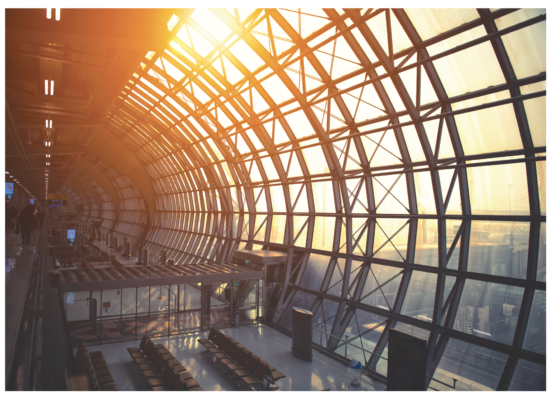
Figure 1. Suvarnabhumi International Airport in Thailand was constructed with excessively transparent materials, causing sunlight to come into the indoor space, particularly direct sunlight.
Buildings 12 02089 g001
Figure 2. An over-glazed façade will cause excessive glare and overheating in interior spaces. The only option for occupants is to install protective measures in their workstations.
Buildings 12 02089 g002
Figure 3. Summary of gaps, problems, and limitations of related works.
Buildings 12 02089 g003
Figure 4. The overall diagram of the research methodology.
Buildings 12 02089 g004
Figure 5. Variant diagram for the comparison of effectiveness.
Buildings 12 02089 g005
Figure 6. The biomimicry design spiral principle for integration in this study.
Buildings 12 02089 g006
Figure 7. Inspiration for a façade merging physical DNA and phototropism behavior.
Buildings 12 02089 g007
Figure 8. Overall generation of the strip phenotype in 450 solutions and the trend of SD. (a) the trend of SD in eight generations; (b) the mean value trendline of the strip forms.
Buildings 12 02089 g008
Figure 9. The probability of the strip phenotype in generation 3 (50 solutions).
Buildings 12 02089 g009
Figure 10. Set-up of the model for simulation in terms of daylight factor.
Buildings 12 02089 g010
Figure 11. The box spaces for simulation in terms of daylight factor.
Buildings 12 02089 g011
Figure 12. Comparing a façade in terms of daylight factors.
Buildings 12 02089 g012
Figure 13. The improvement in the potential of the kinetic façade (version 2: twisting movement). (a) The façade movement pattern after improving; (b) The different degrees of each strip façade in Grasshopper.
Buildings 12 02089 g013
Figure 14. The model for the new design of kinetic façade (version 2: twisting movement) fabrication.
Buildings 12 02089 g014
Figure 15. The kinetic façade (version 2: twisting movement) elements.
Buildings 12 02089 g015
Figure 16. Testing the actual situation (before installing the kinetic façade).
Buildings 12 02089 g016
Figure 17. Testing the actual situation (after installing the kinetic façade).
Buildings 12 02089 g017
Figure 18. The kinetic façade version 2 movement in different time periods.
Buildings 12 02089 g018
Figure 19. Testing in the actual situation, comparing graph trends between before and after installation of the kinetic façade (version 2: twisting movement).
Buildings 12 02089 g019
Figure 20. The kinetic façade (version 2: twisting movement) installation views from outside and inside. (a) The kinetic façade installation (view from outside); (b) The kinetic façade installation (view from inside).
Buildings 12 02089 g020
Figure 21. The kinetic façade guideline for installation cases.
Buildings 12 02089 g021
Table 1. Daylight factor and appearance.
Average DFAppearance
<2%Room looks gloomy.
2% to 5%Predominantly daylit appearance, but supplementary artificial lighting is needed.
>5%The room appears strongly daylit; daytime electric lighting is rarely needed.
Table 2. The results after the simulation of the glass panel alone, the results after the simulation of the kinetic façade (version 2: twisting movement) in terms of LEED version 4.1 criteria for the static façade, and the kinetic façade (version 1: rotating movement) in terms of LEED version 4.1 criteria.
Façade TypeSize, LevelArea (ft2)sDA (%)ASE (%)
Only glass panelLarge, level 1 (L1)121110035
Medium, level 1 (M1)80710033.33
Small, level 1 (S1)40410026.04
Large, level 2 (L2)121110036
Medium, level 2 (M2)80710033.33
Small, level 2 (S2)40410032.29
Total484410033.72
Static façadeL112111000.00
M18071000.00
S140497.920.00
L212111000.00
M28071000.00
S24041000.00
Total484498.830.00
Kinetic façade
(Version 1, 20 deg)
L1121184.000.00
M180783.820.00
S140452.080.00
L2121192.330.00
M280784.310.00
S240457.290.00
Total484481.220.00
Kinetic façade
(Version 1, 50 deg)
L112111000.67
M18071002.45
S140495.831.04
L212111001.00
M28071003.43
S240497.921.04
Total484499.481.57
Kinetic façade
(Version 1, 80 deg)
L112111000.00
M18071001.47
S14041000.00
L212111000.00
M28071004.41
S24041000.00
Total48441000.98
Kinetic façade
(Version 1, 100 deg)
L112111000.00
M18071000.98
S14041000.00
L212111000.00
M28071002.45
S24041000.00
Total48441000.57
Table 3. The results after the simulation of the kinetic façade (version 2: twisting movement) in terms of LEED version 4.1 criteria.
Façade TypeSize, LevelArea (ft2)sDA (%)ASE (%)
Kinetic façade
(Version 2, 20 deg)
L1121184.333.67
M180772.063.92
S140453.133.13
L2121193.334.00
M280783.335.88
S240454.172.08
Total484479.263.98
Kinetic façade
(Version 2, 50 deg)
L1121110015.33
M180710016.67
S140410013.54
L2121110013.00
M280710013.24
S240410010.42
Total484410014.06
Kinetic façade
(Version 2, 80 deg)
L1121110011.33
M180710011.76
S140410010.42
L2121110016.00
M280710015.20
S240410013.54
Total484410013.32
Kinetic façade
(Version 2, 100 deg)
L1121110011.00
M180710011.27
S14041009.38
L2121110016.00
M280710015.69
S240410015.63
Total484410013.33
sDA—spatial daylight autonomy, a measure that specifies a percentage of area that satisfies minimum daylight illuminance levels for a specified fraction of the working hours per year. ASE—the annual sunlight exposure: an indicator revealing the possibility for visual discomfort in inside work environments.
Table 4. Comparing approximate lux value trends between before and after installation of the kinetic façade (version 2: twisting movement).
TimeHours     Illuminance (lux) (Before Installing Kinetic Façade)     Illuminance (lux) (After Installing Kinetic Façade)
8:00 a.m.126,104800
9:00 a.m.25000950
10:00 a.m.34300700
11:00 a.m.44200650
12:00 p.m.53500500
1:00 p.m.63000650
2:00 p.m.73000450
3:00 p.m.81900450
4:00 p.m.91500490
5:00 p.m.101000430
6:00 p.m.1117065
Average 4879.45557.72
Publisher’s Note: MDPI stays neutral with regard to jurisdictional claims in published maps and institutional affiliations.