
Flexural Behavior of Concrete Beams Reinforced with Recycled Plastic Mesh


Abstract
:
1. Introduction
2. Materials and Methods
2.1. Materials
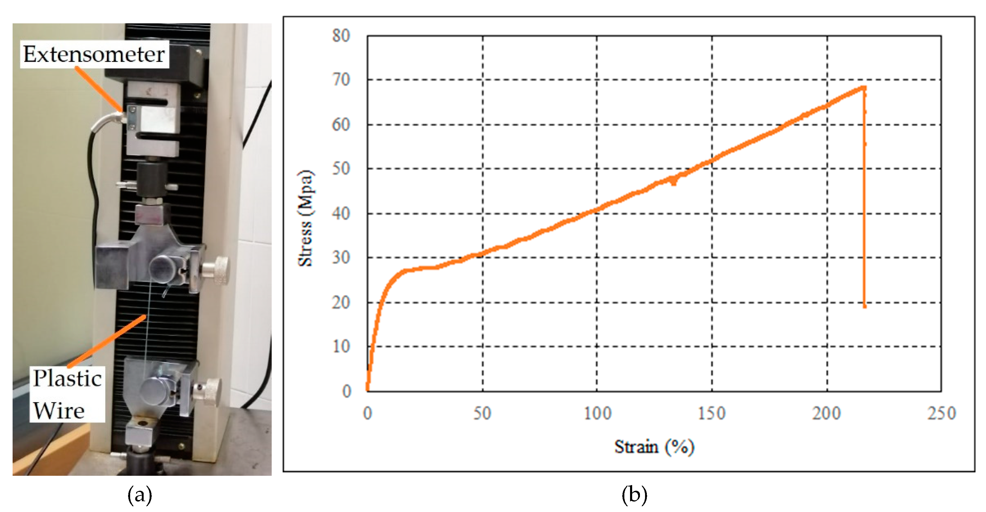
2.1.1. Plastic Fibers
2.1.2. Steel Bars
2.1.3. Concrete
2.2. Experimental Program
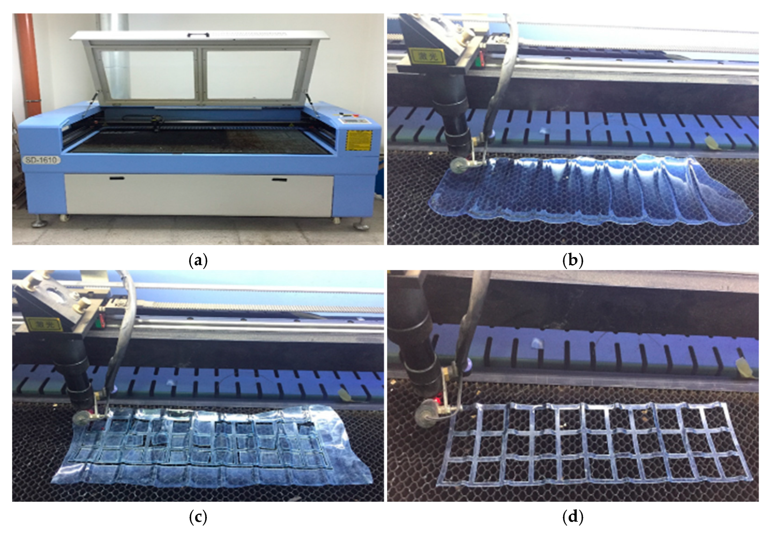
2.2.1. Preparation of Plastic Meshes
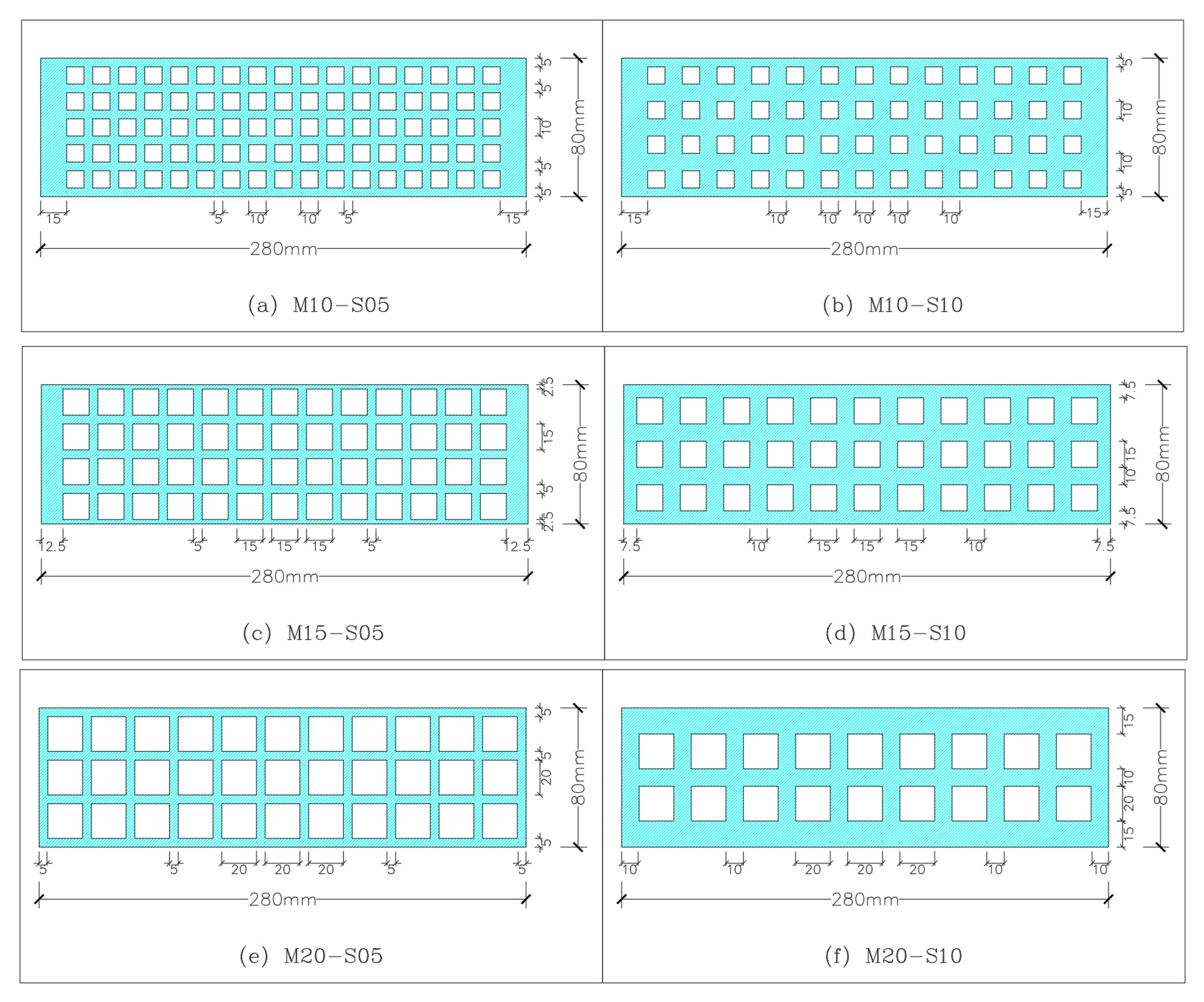
2.2.2. Characteristics of Specimens
2.2.3. Concrete Mix Design
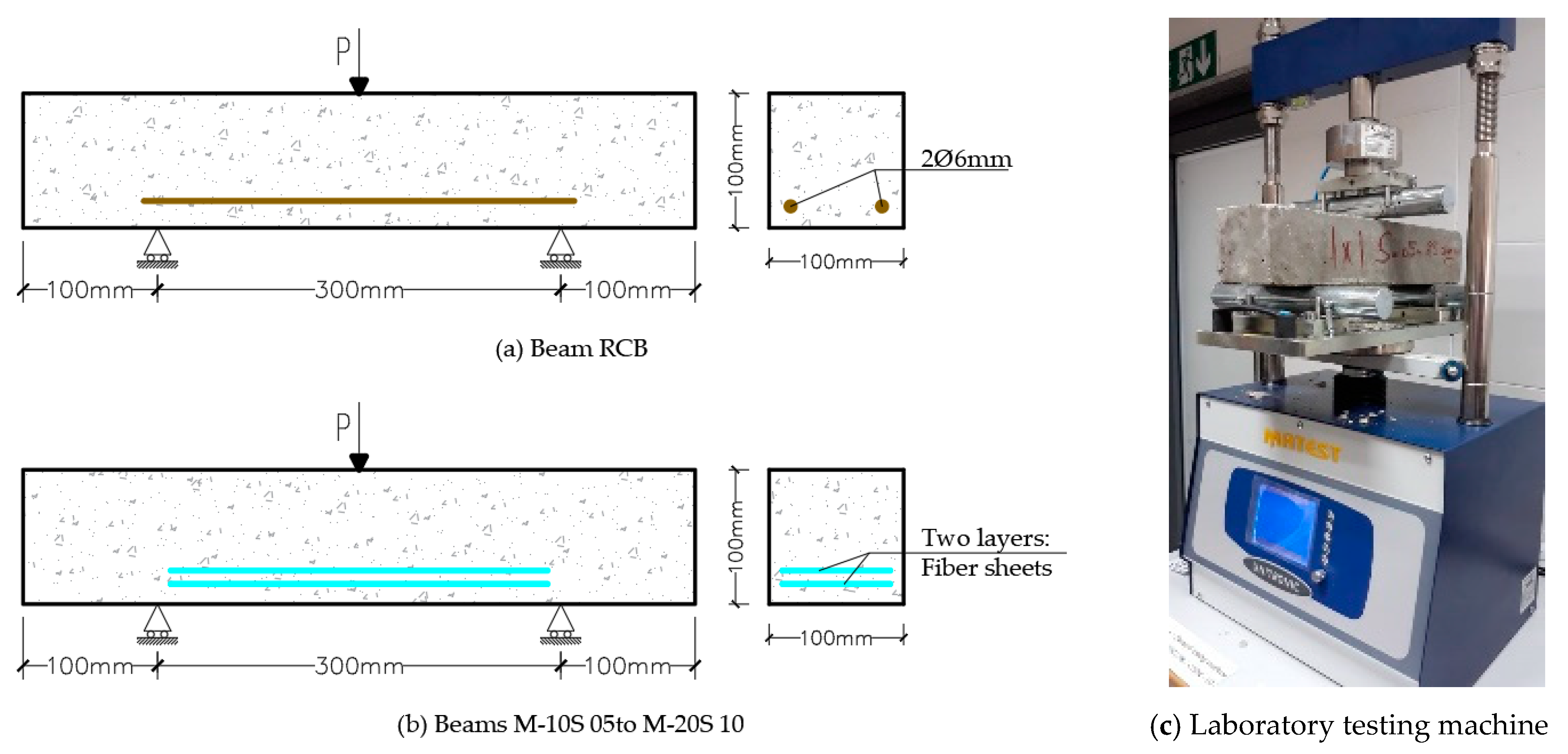
2.2.4. Test Setup
3. Results and Discussion
3.1. Experimental Test
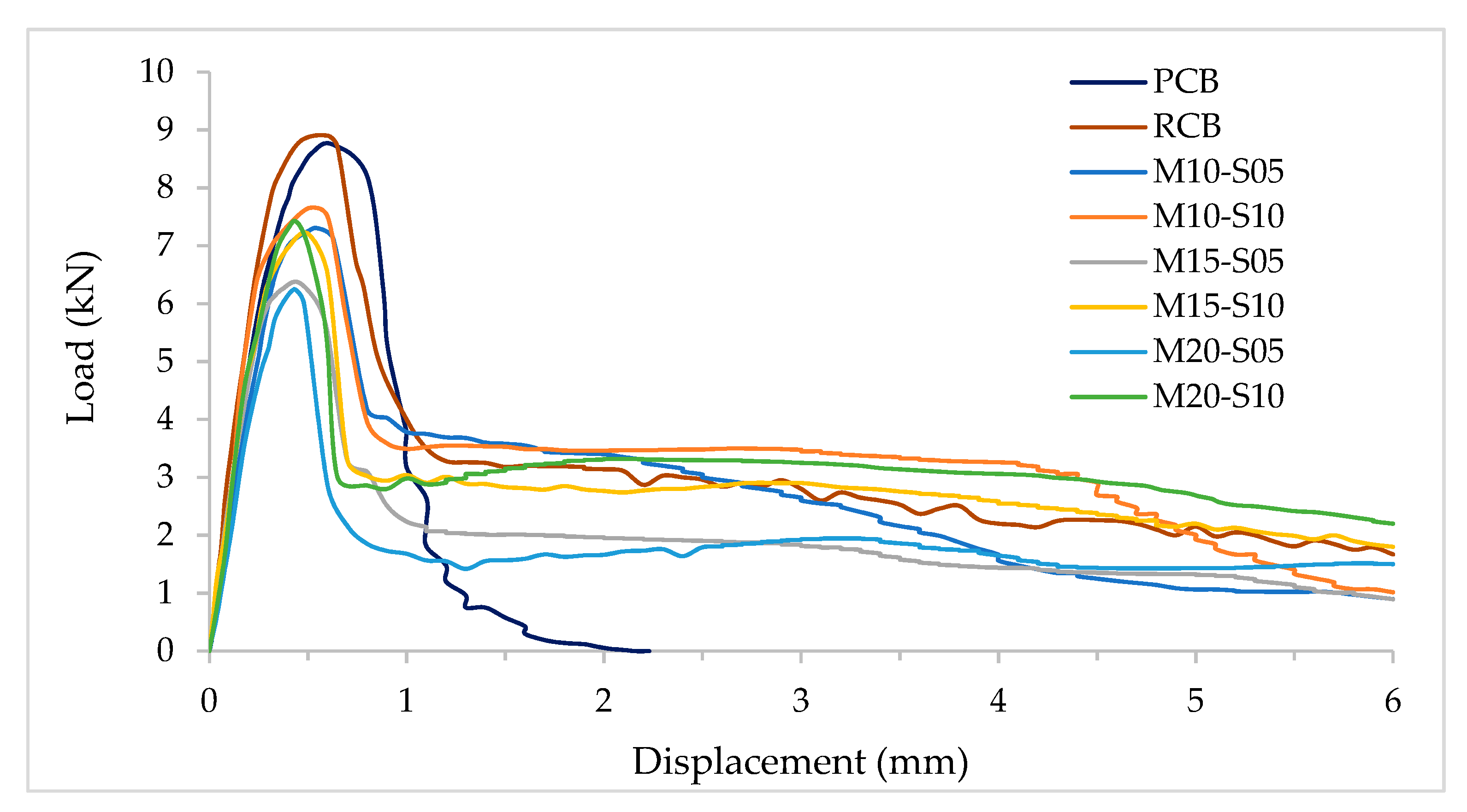
3.1.1. Flexural Behavior
- An elastic zone describing the ascending part where the applied load and the displacement are linearly proportional up to the first hairline crack. The slope of the load displacement curve increases slightly as the ultimate capacity of the beam goes up.
- Beyond the first cracking point, the plastic zone starts. This zone involves the remaining part of the ascending branch where the applied load increases slightly as the deflection increases. At the end of this phase, the beam reaches the ultimate capacity through which cracks undergo further development.
- At the point the beam reaches the ultimate capacity, the damage zone starts indicating the stiffness degradation of the specimen. This phenomenon is well known as the post-cracking phase, in which the stiffness is reduced as the applied strain increases up to the rupture of the plastic sheets. This degradation is accompanied with large deformation induced by the bound between both the plastic meshes and concrete. In other words, the matrix is adhered well by concrete and fibers as a long softening zone remains. The bonding effect of the plastic converts the brittle behavior to a more ductile mode. Thus, the plastic mesh may play a role in controlling the propagation of cracks. At the end, the test was stopped as the deterioration became quite substantial (Figure 9).
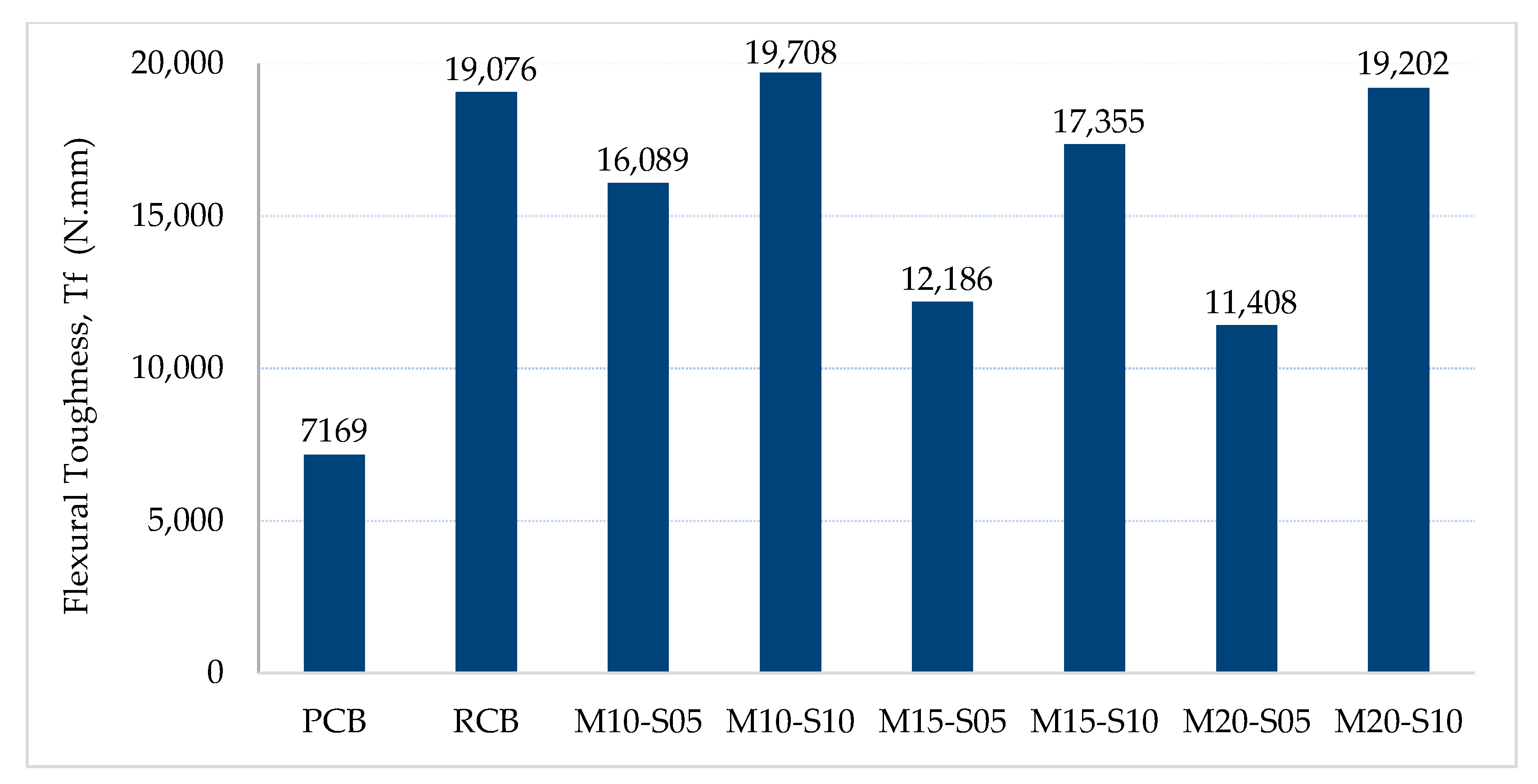
3.1.2. Flexural Toughness
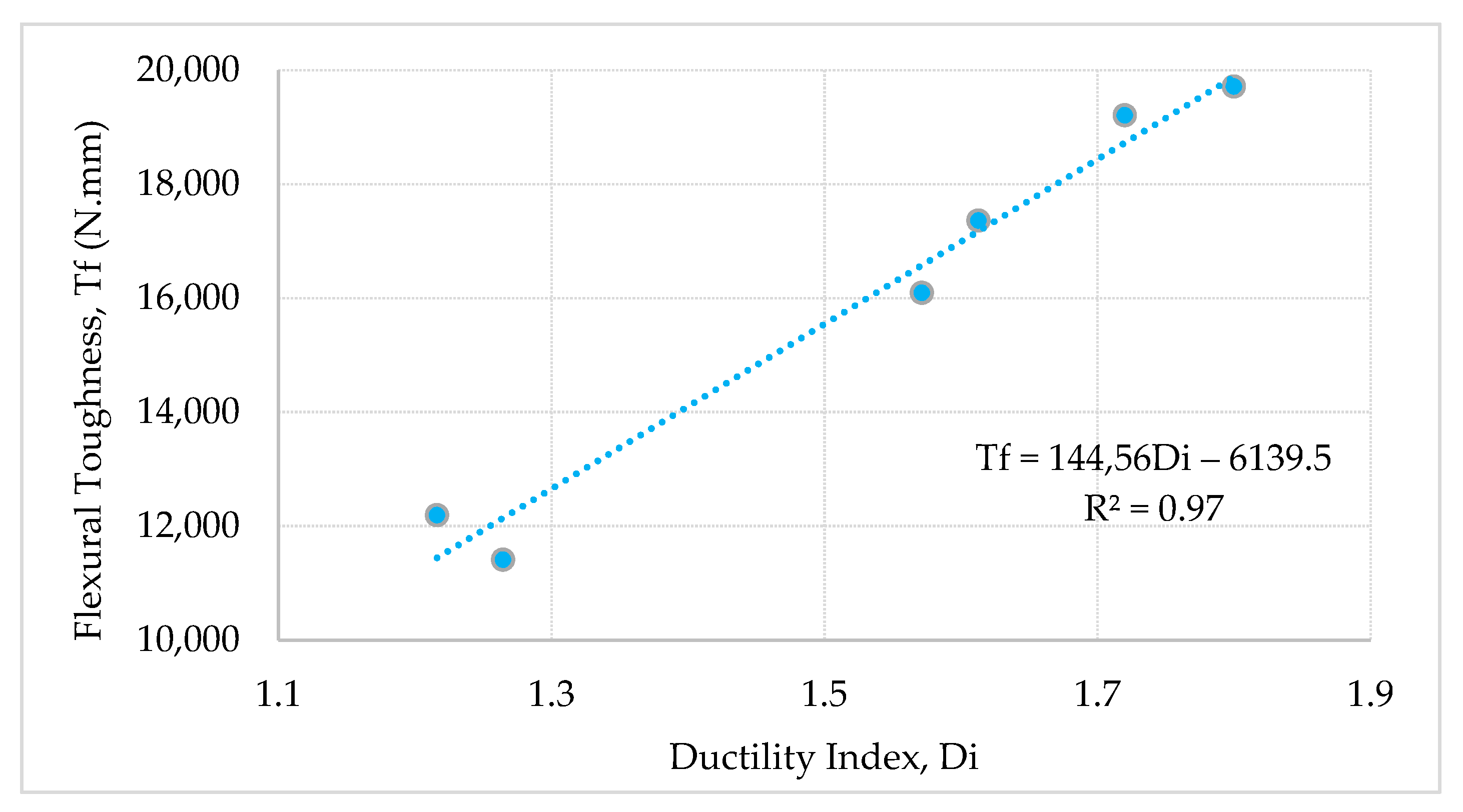
3.1.3. Ductility Index
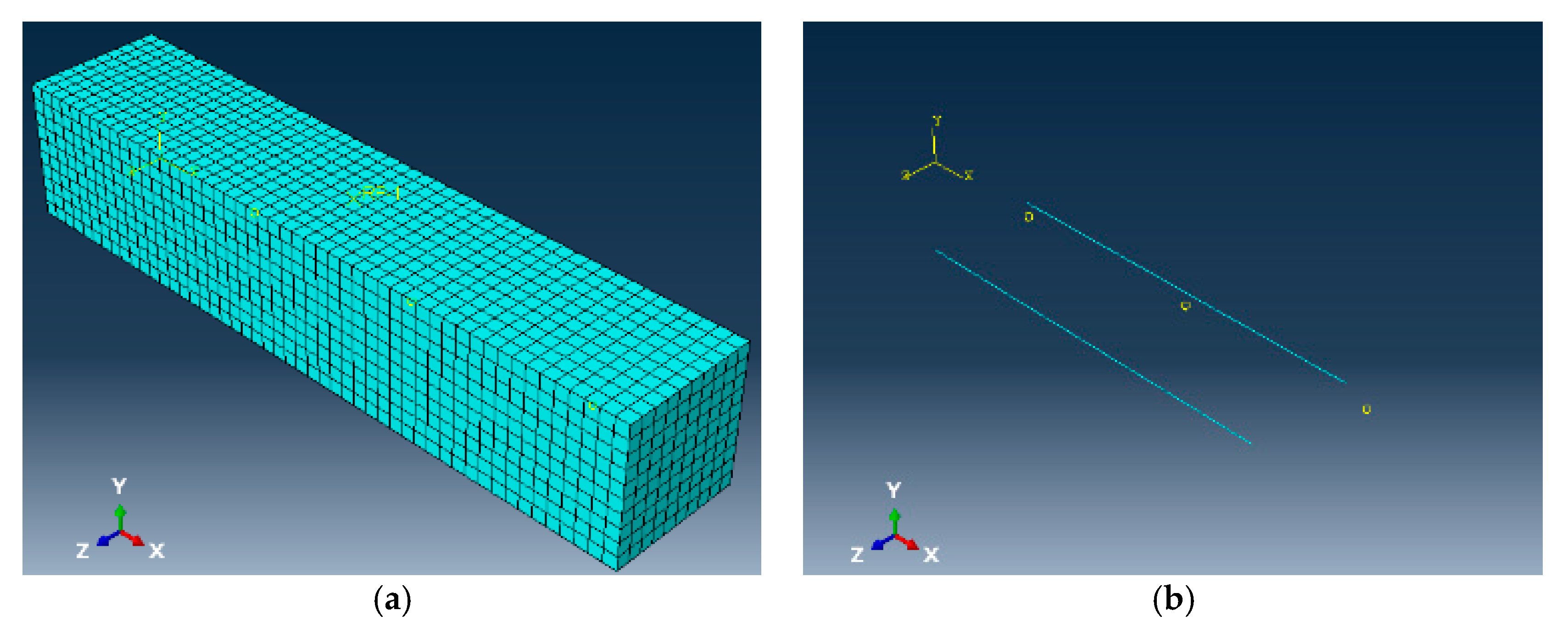
3.2. Finite Element Model
3.2.1. Methodology
3.2.2. Results and Discussion
- 4.
- The first phase starts with the beginning of the simulation up to a load of 6.85 kN. At this limit, the initial crack occurs at the flexural mid-span zone under loading point. This phase represents the elastic part of the curve. The deformation is directly proportional to the load applied. Similarly, the exerting stress is directly proportional to the strain. The yield deflection is observed at 0.29 mm.
- 5.
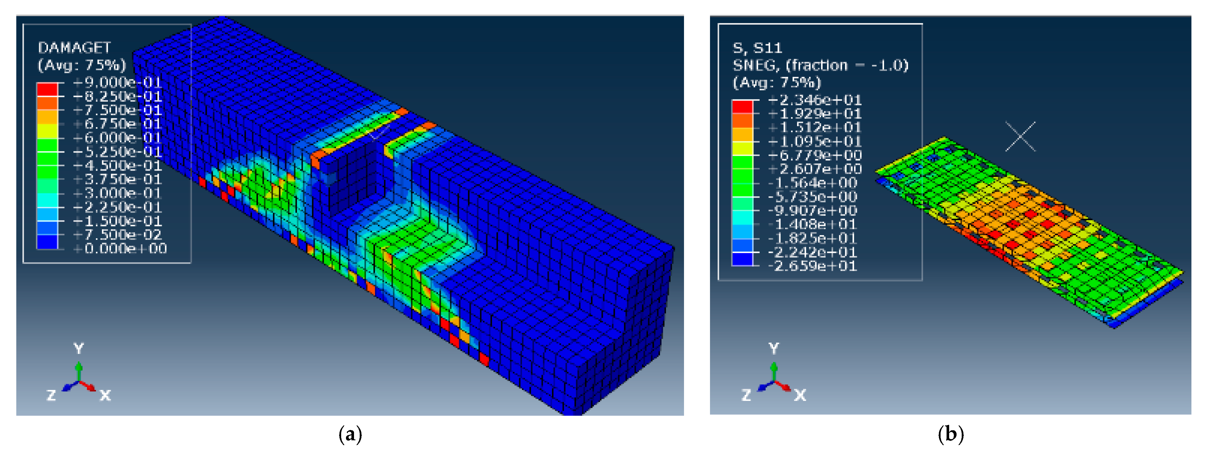
- Beyond the linearity limit, the model exhibits plastic behavior as the stress is not anymore linearly proportional to the strain. This phase illustrates the remaining part of the ascending branch up to a pick of 7.86 kN with an ultimate deflection of 0.53 mm. It can be seen that the load increment rate is smaller than the first phase. Simultaneously, newer cracks develop as older cracks propagate wider and deeper in the bottom flexure zone, and then tend to propagate upward. Likewise, the axial stress S11 in the fiber sheets is early created in the middle third of the beam prior to propagate towards the both ends (Figure 19b). It should be noted that ABAQUS denotes the x, y and z axis as 1, 2 and 3 respectively. Besides, positive values correspond to tensile stresses and forces, while negative ones are for compression.
- 6.
- Afterwards, the post-cracking phase of the model indicates excessive stiffness degradation of the beam. The curve undergoes a nonlinear sharp downward trend. The red volumes seen in Figure 19a represent the crushed concrete volumes. Meanwhile, the beam continues to deform plastically in a long softening way induced by the bond between the fiber and concrete. Consequently, the fiber mesh strongly contributes in enhancing the flexural toughness while restricting the propagation of damaged volumes. The plastic sheets might substitute the role of steel bars in regards. At the end, the model becomes substantially damaged although the FE simulation stops at a large controlled displacement of 6 mm.
4. Conclusions and Recommendations
- 7.
- The experimental testing of concrete beams proves the failure mode of the specimens. As expected, all specimens reinforced with plastic fiber mesh exhibited ductile behavior. This is likely to be due to the presence of plastic meshes which may control the extent of cracks. The good bonding between concrete and fibers converts the brittle behavior to a more ductile mode.
- 8.
- The effect of mesh effective width on the ultimate load of the beam is very dependent. The load carrying capacity of the member goes up as the mesh effective width is larger. Therefore, the use of plastic meshes improves the behavior of the beam while acting as bridge across cracks and leads to delay cracks fast propagation. Accordingly, a simplified linear correlation with high accuracy (R2 = 0.93), was developed between the mesh width ratio and the beam ultimate capacity.
- 9.
- The correlation between the mesh effective width and the flexural toughness shows a positive correlation with R2 value equal to 0.98. The higher the mesh width ratio is, the higher the flexural toughness is. Contrarily, beams with low width ratio do not have the same energy absorption potential as those of higher ratio.
- 10.
- There exists a high correlation between the void ratio and the flexural toughness (R2 = 0.96). The relationship is inversely proportional. As the mesh void ratio increases, the flexural toughness decreases. This drop in flexural toughness is expected as the plastic meshes remain unable to sustain more stress prior to collapse.
- 11.
- Concrete beams with large plastic mesh effective width display high ductility indices. A linear regression was developed between the mesh width ratio and the ductility index. It was found that the relation is proportional with a coefficient of regression R2 equal to 97%. The improvement in ductility index for beams layered with plastic meshes is a promoting finding that may be considered as a guidance for concrete beams subjected to flexural load where high ductility is required.
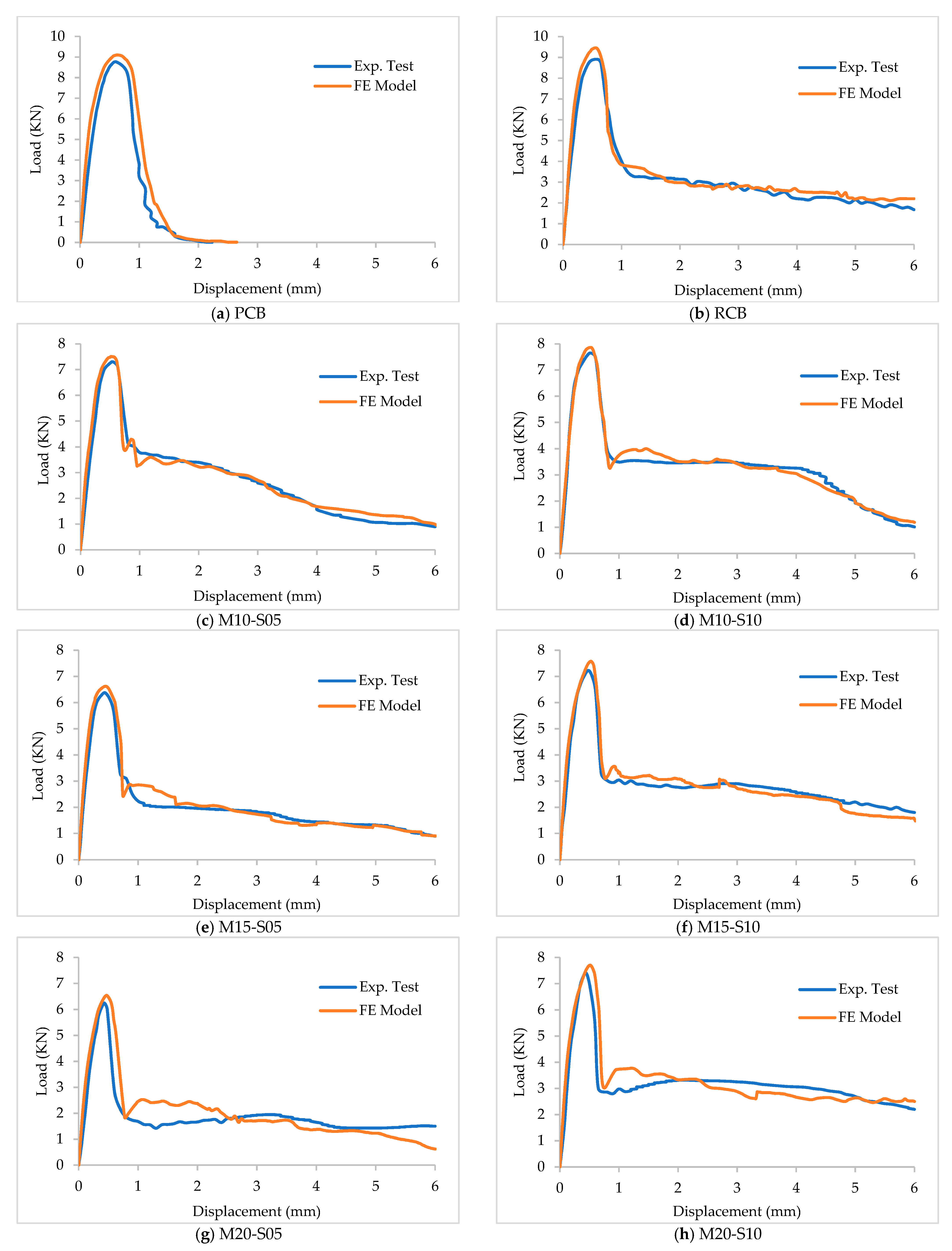
- 12.
- The comparison between the experimental and numerical results demonstrated the accuracy of CDP model to simulate the flexural behavior of beams with plastic meshes under the 3-point loading test. The average error in the simulation was less than 6%.
- 13.
- The results obtained are based on the dimensions of the beams used in this investigation. Future research should examine the behavior of full scale beams containing waste plastic mesh. Different void ratios and mesh configurations should be attempted in order to obtain the optimal performance. Also, using waste plastic fibers in conjunction with plastic mesh should form part of a future work.
Author Contributions
Funding
Institutional Review Board Statement
Informed Consent Statement
Data Availability Statement
Acknowledgments
Conflicts of Interest
References
- Qaidi, S.; Najm, H.M.; Abed, S.M.; Özkılıç, Y.O.; Al Dughaishi, H.; Alosta, M.; Sabri, M.M.; Alkhatib, F.; Milad, A. Concrete Containing Waste Glass as an Environmentally Friendly Aggregate: A Review on Fresh and Mechanical Characteristics. Materials 2022, 15, 6222. [Google Scholar] [CrossRef]
- Çelik, A.İ.; Özkılıç, Y.O.; Zeybek, Ö.; Özdöner, N.; Tayeh, B.A. Performance Assessment of Fiber-Reinforced Concrete Produced with Waste Lathe Fibers. Sustainability 2022, 14, 11817. [Google Scholar] [CrossRef]
- Karalar, M.; Özkılıç, Y.O.; Deifalla, A.F.; Aksoylu, C.; Arslan, M.H.; Ahmad, M.; Sabri, M.M. Improvement in Bending Performance of Reinforced Concrete Beams Produced with Waste Lathe Scraps. Sustainability 2022, 14, 12660. [Google Scholar] [CrossRef]
- Aksoylu, C.; Özkılıç, Y.O.; Hadzima-Nyarko, M.; Işık, E.; Arslan, M.H. Investigation on Improvement in Shear Performance of Reinforced-Concrete Beams Produced with Recycled Steel Wires from Waste Tires. Sustainability 2022, 14, 13360. [Google Scholar] [CrossRef]
- Karalar, M.; Bilir, T.; Çavuşlu, M.; Özkiliç, Y.O.; Sabri, M.M.S. Use of recycled coal bottom ash in reinforced concrete beams as replacement for aggregate. Front. Mater. 2022, 9, 1064604. [Google Scholar] [CrossRef]
- Machaka, M.; Khatib, J.; Elkordi, A.; Ghanem, H.; Baalbaki, O. Selected properties of concrete containing Municipal Solid Waste Incineration Bottom Ash (MSWI-BA). In Proceedings of the 5th International Conference on Sustainable Construction Materials and Technologies (SCMT5); Kingston University: London, UK, 2019; pp. 14–17. [Google Scholar]
- Baalbaki, O.; Elkordi, A.; Ghanem, H.; Machaka, M.; Khatib, J.M. Properties of concrete made of fine aggregates partially replaced by incinerated municipal solid waste bottom ash. Acad. J. Civ. Eng. 2019, 37, 532–538. [Google Scholar]
- Rathore, R.S.; Chouhan, H.S.; Prakash, D. Influence of plastic waste on the performance of mortar and concrete: A review. Mater. Today Proc. 2021, 47, 4708–4711. [Google Scholar] [CrossRef]
- Bahij, S.; Omary, S.; Feugeas, F.; Faqiri, A. Fresh and hardened properties of concrete containing different forms of plastic waste–A review. Waste Manag. 2020, 113, 157–175. [Google Scholar] [CrossRef] [PubMed]
- Gu, L.; Ozbakkaloglu, T. Use of recycled plastics in concrete: A critical review. Waste Manag. 2016, 51, 19–42. [Google Scholar] [CrossRef] [PubMed]
- Siddique, R.; Khatib, J.; Kaur, I. Use of recycled plastic in concrete: A review. Waste Manag. 2008, 28, 1835–1852. [Google Scholar] [CrossRef] [PubMed]
- Sharma, R.; Bansal, P.P. Use of different forms of waste plastic in concrete—A review. J. Clean. Prod. 2016, 112, 473–482. [Google Scholar] [CrossRef]
- Saikia, N.; de Brito, J. Use of plastic waste as aggregate in cement mortar and concrete preparation: A review. Constr. Build. Mater. 2012, 34, 385–401. [Google Scholar] [CrossRef]
- Almeshal, I.; Tayeh, B.A.; Alyousef, R.; Alabduljabbar, H.; Mohamed, A.M.; Alaskar, A. Use of recycled plastic as fine aggregate in cementitious composites: A review. Constr. Build. Mater. 2020, 253, 119146. [Google Scholar] [CrossRef]
- UN Environment Programme. UNEP. 2022. Available online: https://www.unep.org/interactives/beat-plastic-pollution/ (accessed on 25 August 2022).
- Plastics Europe. Plastics-the facts 2021. In An Analysis of European Latest Plastics Production, Demand and Waste Data; Plastics Europe: Brussels, Belgium, 2021. [Google Scholar]
- Singh, N.; Hui, D.; Singh, R.; Ahuja, I.P.; Feo, L.; Fraternali, F. Recycling of plastic solid waste: A state of art review and future applications. Compos. Part B Eng. 2017, 115, 409–422. [Google Scholar] [CrossRef]
- Ismail, Z.Z.; Al-Hashmi, E.A. Use of waste plastic in concrete mixture as aggregate replacement. Waste Manag. 2008, 28, 2041–2047. [Google Scholar] [CrossRef] [PubMed]
- Ali, O.K.; Al-Hadithi, A.I.; Noaman, A.T. Flexural performance of layered PET fiber reinforced concrete beams. Structures 2022, 35, 55–67. [Google Scholar]
- Goumans, J.; van der Sloot, H.; Aalbers, T. Waste materials in construction. In Studies in Environmental Science; Elsevier Science Publishing Company Inc.: New York, NY, USA, 1991; Volume 48. [Google Scholar]
- Alhazmi, H.; Almansour, F.H.; Aldhafeeri, Z. Plastic waste management: A review of existing life cycle assessment studies. Sustainability 2021, 13, 5340. [Google Scholar] [CrossRef]
- Safi, B.; Saidi, M.; Aboutaleb, D.; Maallem, M. The use of plastic waste as fine aggregate in the self-compacting mortars: Effect on physical and mechanical properties. Constr. Build. Mater. 2013, 43, 436–442. [Google Scholar] [CrossRef]
- Adnan, H.M.; Dawood, A.O. Recycling of plastic box waste in the concrete mixture as a percentage of fine aggregate. Constr. Build. Mater. 2021, 284, 122666. [Google Scholar] [CrossRef]
- Islam, M.J.; Shahjalal, M.; Haque, N.M. Mechanical and durability properties of concrete with recycled polypropylene waste plastic as a partial replacement of coarse aggregate. J. Build. Eng. 2022, 54, 104597. [Google Scholar] [CrossRef]
- Ibrahim, A.A.; Najla’a, H.; Jaber, M.H.; Hassan, R.F.; Hussein, H.H.; Al-Salim, N.H. Experimental investigation of flexural and shear behaviors of reinforced concrete beam containing fine plastic waste aggregates. Structures 2022, 43, 834–846. [Google Scholar] [CrossRef]
- Ozbakkaloglu, T.; Gu, L.; Gholampour, A. Short-term mechanical properties of concrete containing recycled polypropylene coarse aggregates under ambient and elevated temperature. J. Mater. Civ. Eng. 2017, 29, 04017191. [Google Scholar] [CrossRef]
- Islam, M.J.; Meherier, M.S.; Islam, A.R. Effects of waste PET as coarse aggregate on the fresh and harden properties of concrete. Constr. Build. Mater. 2016, 125, 946–951. [Google Scholar] [CrossRef]
- Kore, S.D. Feasibility Study on Use of Plastic Waste as Fine Aggregate in Concrete Mixes. J. Build. Mater. Sci. 2019, 2019, 1204. [Google Scholar] [CrossRef]
- Hama, S.M. Behavior of concrete incorporating waste plastic as fine aggregate subjected to compression, impact load and bond resistance. Eur. J. Environ. Civ. Eng. 2022, 26, 3372–3386. [Google Scholar] [CrossRef]
- Bag, R.; Agarwal, A.; Praneeth, R. Recycling of domestic plastic waste bags as fine aggregate in concrete. IOP Conf. Ser. Mater. Sci. Eng. 2020, 936, 012009. [Google Scholar] [CrossRef]
- Juki, M.I.; Awang, M.; Annas, M.M.; Boon, K.H.; Othman, N.; Roslan, M.A.; Khalid, F.S. Relationship between compressive, splitting tensile and flexural strength of concrete containing granulated waste polyethylene terephthalate (PET) bottles as fine aggregate. Adv. Mater. Res. 2013, 795, 356–359. [Google Scholar] [CrossRef] [Green Version]
- Bamigboye, G.; Tarverdi, K.; Adigun, D.; Daniel, B.; Okorie, U.; Adediran, J. An appraisal of the mechanical, microstructural, and thermal characteristics of concrete containing waste PET as coarse aggregate. Clean. Waste Syst. 2022, 1, 100001. [Google Scholar] [CrossRef]
- Khatib, J.M.; Herki, B.A.; Elkordi, A. Characteristics of concrete containing EPS. In Use of Recycled Plastics in Eco-Efficient Concrete; Elsevier: Amsterdam, The Netherlands, 2019; pp. 137–165. [Google Scholar]
- Pacheco-Torgal, F.; Khatib, J.; Colangelo, F.; Tuladhar, R. (Eds.) Use of Recycled Plastics in Eco-Efficient Concrete; Woodhead Publishing: New York, NY, USA, 2018. [Google Scholar]
- Foti, D. Preliminary analysis of concrete reinforced with waste bottles PET fibers. Constr. Build. Mater. 2011, 25, 1906–1915. [Google Scholar] [CrossRef]
- Al-Tulaian, B.S.; Al-Shannag, M.J.; Al-Hozaimy, A.R. Recycled plastic waste fibers for reinforcing Portland cement mortar. Constr. Build. Mater. 2016, 127, 102–110. [Google Scholar] [CrossRef]
- Mercante, I.; Alejandrino, C.; Ojeda, J.P.; Chini, J.; Maroto, C.; Fajardo, N. Mortar and concrete composites with recycled plastic: A review. Sci. Technol. Mater. 2018, 30, 69–79. [Google Scholar] [CrossRef]
- Irmawaty, R.; Parung, H.; Djamaluddin, R.; Amiruddin, A.A.; Faturrahman, M.P. Mechanical Properties of Concrete Using Plastic Waste. IOP Conf. Ser. Mater. Sci. Eng. 2020, 875, 012019. [Google Scholar] [CrossRef]
- Saikia, N.; De Brito, J. Mechanical properties and abrasion behaviour of concrete containing shredded PET bottle waste as a partial substitution of natural aggregate. Constr. Build. Mater. 2014, 52, 236–244. [Google Scholar] [CrossRef]
- Juki, M.I.; Muhamad, K.; Annas, M.M.; Boon, K.H.; Othman, N.; Asyraf, R.M.; Khalid, F.S. Development of concrete mix design nomograph containing polyethylene terephtalate (PET) as fine aggregate. Adv. Mater. Res. 2013, 701, 12–16. [Google Scholar] [CrossRef] [Green Version]
- Frigione, M. Recycling of PET bottles as fine aggregate in concrete. Waste Manag. 2010, 30, 1101–1106. [Google Scholar] [CrossRef]
- Shaikh, F.U. Tensile and flexural behaviour of recycled polyethylene terephthalate (PET) fibre reinforced geopolymer composites. Constr. Build. Mater. 2020, 245, 118438. [Google Scholar] [CrossRef]
- Irmawaty, R.; Djamaluddin, R. Flexural behavior of monolith and hybrid concrete beams produced through the partial replacement of coarse aggregate with PET waste. Structures 2022, 43, 1134–1144. [Google Scholar]
- Abdullah, Q.M.; Haido, J.H. Response of hybrid concrete incorporating eco-friendly waste PET fiber: Experimental and analytical investigations. Constr. Build. Mater. 2022, 354, 129071. [Google Scholar] [CrossRef]
- Khatib, J.M.; Jahami, A.; Elkordi, A.; Abdelgader, H.; Sonebi, M. Structural assessment of reinforced concrete beams incorporating waste plastic straws. Environments 2020, 7, 96. [Google Scholar] [CrossRef]
- Khatib, J.; Jahami, A.; Elkordi, A.; Baalbaki, O. Structural performance of reinforced concrete beams containing plastic waste caps. Mag. Civ. Eng. 2019, 7, 73–79. [Google Scholar]
- Alani, A.H.; Johari, M.A.; Noaman, A.T.; Bunnori, N.M.; Majid, T.A. Effect of the incorporation of PET fiber and ternary blended binder on the flexural and tensile behaviour of ultra-high performance green concrete. Constr. Build. Mater. 2022, 331, 127306. [Google Scholar] [CrossRef]
- Mohammed, A.A. Flexural behavior and analysis of reinforced concrete beams made of recycled PET waste concrete. Constr. Build. Mater. 2017, 155, 593–604. [Google Scholar] [CrossRef]
- Hawileh, R.A.; Mhanna, H.H.; Al Rashed, A.; Abdalla, J.A.; Naser, M.Z. Flexural behavior of RC beams externally bonded with polyethylene terephthalate (PET) fiber reinforced polymer (FRP) laminates. Eng. Struct. 2022, 256, 114036. [Google Scholar] [CrossRef]
- ASTM D638; Standard Test Method for Tensile Properties of Plastics. ASTM International: West Conshohocken, PA, USA, 2014.
- ASTM A615; Standard Specification for Deformed and Plain Carbon-Steel Bars for Concrete Reinforcement. ASTM International: West Conshohocken, PA, USA, 2015.
- ASTM C150; Standard Specification for Portland Cement. American Society for Testing and Materials: West Conshohocken, PA, USA, 2001.
- ASTM C33; Standard Specification for Concrete Aggregates. ASTM International: West Conshohocken, PA, USA, 2018.
- ASTM C39; Standard Test Method for Compressive Strength of Cylindrical Concrete Specimens. ASTM International: West Conshohocken, PA, USA, 2021.
- ASTM C293; Standard Test Method for Flexural Strength of Concrete (Using Simple Beam with Third-Point Loading). ASTM International: West Conshohocken, PA, USA, 2010.
- Özkılıç, Y.O.; Aksoylu, C.; Arslan, M.H. Numerical evaluation of effects of shear span, stirrup spacing and angle of stirrup on reinforced concrete beam behaviour. Struct. Eng. Mech. Int. J. 2021, 79, 309–326. [Google Scholar]
- Chahal, S.; Baalbaki, O.; Timsah, Y.; Ghanem, H.; Abu Saleh, Z. Performance of two-way hinges in reinforced concrete structure. Mag. Civ. Engineering. 2021, 102, 10204. [Google Scholar] [CrossRef]
- Özkılıç, Y.O.; Aksoylu, C.; Gemi, L.; Arslan, M.H. Behavior of CFRP-strengthened RC beams with circular web openings in shear zones: Numerical study. Structures 2022, 41, 1369–1389. [Google Scholar] [CrossRef]
- Lee, J.; Fenves, G. Plastic-damage model for cyclic loading of concrete structure. Eng. Mech. 1998, 124, 892–900. [Google Scholar] [CrossRef]
- Lublinear, J.; Oliver, J.; Oller, S.; Onate, E. A plastic-damage model for concrete. Solids Struct. 1989, 25, 299–326. [Google Scholar] [CrossRef]
- Aksoylu, C.; Özkılıç, Y.O.; Arslan, M.H. Damages on prefabricated concrete dapped-end purlins due to snow loads and a novel reinforcement detail. Eng. Struct. 2020, 225, 111225. [Google Scholar] [CrossRef]
- Özkılıç, Y.O.; Aksoylu, C.; Arslan, M.H. Experimental and numerical investigations of steel fiber reinforced concrete dapped-end purlins. J. Build. Eng. 2021, 36, 102119. [Google Scholar] [CrossRef]


| Parameter | Unit | Symbol | Plastic Fibers |
|---|---|---|---|
| Modulus of elasticity | MPa | E1 | 313 |
| Yield strength | MPa | fy | 27.2 |
| Ultimate strength | MPa | fu | 68.4 |
| Poisson’s ratio | ν | 0.35 | |
| Water absorption | % | 0.00 | |
| Density | KN/m3 | ρ | 9.45 |
| Parameter | Unit | Symbol | Steel Bars |
|---|---|---|---|
| Modulus of elasticity | MPa | Et | 200,000 |
| Yield strength | MPa | fy | 240 |
| Ultimate strength | MPa | fu | 300 |
| Poisson’s ratio | ν | 0.3 | |
| Density | KN/m3 | ρ | 78.5 |
| Material | Cement | Sand | Gravel | Water |
|---|---|---|---|---|
| Amount (kg/m3) | 300 | 650 | 1310 | 240 |
| Beam | Mesh Void Ratio, Vr | Mesh Effective Width (mm) | Mesh Width Ratio, Wr | Ultimate Capacity, Pu (KN) | Flexural Toughness, Tf (N.mm) | Yield Deflection (mm) | Ultimate Deflection (mm) | Ductility Index, Di |
|---|---|---|---|---|---|---|---|---|
| PCB | - | - | 8.75 | 7169 | 0.52 | 0.60 | 1.15 | |
| RCB | - | - | 8.90 | 19,076 | 0.35 | 0.60 | 1.71 | |
| M10-S05 | 0.38 | 30 | 0.38 | 7.25 | 16,089 | 0.35 | 0.55 | 1.57 |
| M10-S10 | 0.26 | 40 | 0.50 | 7.64 | 19,708 | 0.22 | 0.40 | 1.80 |
| M15-S05 | 0.52 | 20 | 0.25 | 6.37 | 12,186 | 0.37 | 0.45 | 1.22 |
| M15-S10 | 0.33 | 35 | 0.44 | 7.21 | 17,355 | 0.31 | 0.50 | 1.61 |
| M20-S05 | 0.59 | 20 | 0.25 | 6.25 | 11,408 | 0.34 | 0.43 | 1.26 |
| M20-S10 | 0.32 | 40 | 0.50 | 7.43 | 19,202 | 0.25 | 0.43 | 1.72 |
| Parameter | Unit | Symbol | Value |
|---|---|---|---|
| Compressive strength | MPa | f’c | 15 |
| Tensile strength | MPa | ft | 2.40 |
| Modulus of elasticity | MPa | Ec | 18,203 |
| Poisson’s ratio | ν | 0.2 | |
| Density | KN/m3 | ρ | 24 |
| Dilation angle | ° | ψ | 30 |
| Eccentricity | ɛ | 0.1 | |
| Bi-axial to uni-axial strength ratio | fb0/ft0 | 1.16 | |
| Second stress invariant ratio | K | 0.667 | |
| Viscosity parameter | μ | 0.00001 |
| Failure Mode | Equation |
|---|---|
| Tensile fiber failure | |
| Compressive fiber failure | |
| Tensile matrix failure | |
| Compressive matrix failure |
| Model | Ultimate Capacity, Pu (KN) | Flexural Toughness, Tf (N.mm) | Ductility Index, Di | ||||||
|---|---|---|---|---|---|---|---|---|---|
| Exp. Test | FE Model | % of Error | Exp. Test | FE Model | % of Error | Exp. Test | FE Model | % of Error | |
| PCB | 8.75 | 9.10 | 4% | 7169 | 8775 | 22% | 1.15 | 1.24 | 7% |
| RCB | 8.90 | 9.43 | 6% | 19,076 | 20,184 | 6% | 1.71 | 1.81 | 6% |
| M10-S05 | 7.25 | 7.51 | 4% | 16,089 | 16,502 | 3% | 1.57 | 1.63 | 3% |
| M10-S10 | 7.64 | 7.86 | 3% | 19,708 | 19,907 | 1% | 1.80 | 1.83 | 2% |
| M15-S05 | 6.37 | 6.62 | 4% | 12,186 | 12,884 | 6% | 1.22 | 1.30 | 7% |
| M15-S10 | 7.21 | 7.57 | 5% | 17,355 | 17,362 | 0% | 1.61 | 1.66 | 3% |
| M20-S05 | 6.25 | 6.53 | 5% | 11,408 | 12,254 | 7% | 1.26 | 1.33 | 5% |
| M20-S10 | 7.43 | 7.71 | 4% | 19,202 | 19,681 | 2% | 1.72 | 1.76 | 2% |
Publisher’s Note: MDPI stays neutral with regard to jurisdictional claims in published maps and institutional affiliations. |
© 2022 by the authors. Licensee MDPI, Basel, Switzerland. This article is an open access article distributed under the terms and conditions of the Creative Commons Attribution (CC BY) license (https://creativecommons.org/licenses/by/4.0/).
Share and Cite
Ghanem, H.; Chahal, S.; Khatib, J.; Elkordi, A. Flexural Behavior of Concrete Beams Reinforced with Recycled Plastic Mesh. Buildings 2022, 12, 2085. https://doi.org/10.3390/buildings12122085
Ghanem H, Chahal S, Khatib J, Elkordi A. Flexural Behavior of Concrete Beams Reinforced with Recycled Plastic Mesh. Buildings. 2022; 12(12):2085. https://doi.org/10.3390/buildings12122085
Chicago/Turabian StyleGhanem, Hassan, Safwan Chahal, Jamal Khatib, and Adel Elkordi. 2022. "Flexural Behavior of Concrete Beams Reinforced with Recycled Plastic Mesh" Buildings 12, no. 12: 2085. https://doi.org/10.3390/buildings12122085
APA StyleGhanem, H., Chahal, S., Khatib, J., & Elkordi, A. (2022). Flexural Behavior of Concrete Beams Reinforced with Recycled Plastic Mesh. Buildings, 12(12), 2085. https://doi.org/10.3390/buildings12122085